

Page 1

Manual BioLite
MultiSpectral Light Source
Installation and User Instructions
™
UVP, LLC Ultra-Violet Products Ltd.
2066 W. 11th Street Unit 1, Trinity Hall Farm Estate
Upland, CA 91786 Nuffield Road, Cambridge CB4 1TG UK
Phone: (800) 452-6788 Phone: +44(0)1223-420022
Fax: (909) 946-3597 Fax: +44(0)1223-420561
Web Site: www.uvp.com
81-0248-01 Rev E
Page 2

Manual BioLite MultiSpectral Light Source 2
Table of Contents
Introduction .................................................................................................................................................................. 3
System Components ................................................................................................................................................... 4
Specifications ............................................................................................................................................................ 4
Output Spectrum ....................................................................................................................................................... 5
Wavelength (nm) ....................................................................................................................................................... 5
Safety Information ..................................................................................................................................................... 5
Setup Instructions ........................................................................................................................................................ 6
Using the Light Source .............................................................................................................................................. 10
Service Procedures .................................................................................................................................................... 11
Bulb Replacement ................................................................................................................................................... 11
Return Procedure .................................................................................................................................................... 12
Replacement Parts and Accessories ....................................................................................................................... 12
Troubleshooting ....................................................................................................................................................... 12
Care and Cleaning .................................................................................................................................................. 13
Technical Support ................................................................................................................................................... 13
Page 3

Manual BioLite MultiSpectral Light Source 3
Introduction
The Manual BioLite MultiSpectral Light Source is a 150 watt quartz halogen light source designed for use
with select UVP Advanced Imaging Systems. The unit features a six position mechanical dimmer permitting
variable intensity, as well as easily exchangeable excitation filters for monochromatic light output. A closed
optical path tightly controls the output spectrum, allowing for consistent repeatable measurements with
superior signal to noise.
Page 4
Manual BioLite MultiSpectral Light Source 4
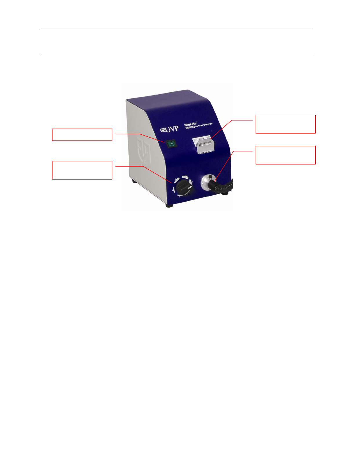
Master Power Switch
Light Intensity
Excitation Filter
Fiber Optic Port and
System Components
Refer to the packing slip and schematic shown below for specific parts and components included with the
BioLite MultiSpectral Light Source.
Cartridge
Cable
Selector Knob
Specifications
Color Temperature: 3250°K
Bulb Type: 150 Watt Halogen Type EKE
Ferrule Dimension: 0.718 inch (18.2 mm)
Physical Dimensions:
Height 8.75 Inches (22 cm)
Width 7 Inches (18 cm)
Depth 10 Inches (25 cm)
Weight 9 pounds (4 kg)
Power Requirements:
115V 3 Amps max, 50/60 Hz
230V 1.5 Amps max. 50/60 Hz
100V 3 Amps max, 50/60 Hz
Page 5

Manual BioLite MultiSpectral Light Source 5
Intensity
Output Spectrum
The graph below displays the spectral emission curve for the halogen light source within the BioLite (shown
without filtering):
Safety Information
WARNING: The device will overheat if the fan outlet on the back of the BioLite is blocked.
WARNING: The quartz halogen bulb becomes very hot with use. Do not open the bottom access panel
while the BioLite is running or without allowing it to fully cool.
CAUTION: Never touch the inner portion of the quartz halogen bulb. If it accidentally comes in contact with
skin, carefully clean the glass with rubbing alcohol and a clean, lint free cloth.
CAUTION: Never look into the output port or fiber optic bundle of the BioLite when it is on, as the intense
light may hurt your eyes.
Wavelength (nm)
Page 6

Manual BioLite MultiSpectral Light Source 6
Epi Light Guides
Stopper
Fiber Optic Cable
Setup Instructions
BioLite MultiSpec tral Light Source Setup
1. Plug the power cord into the receptacle on the back of the unit and t he other end to a pow er outlet .
2. Position the BioLIte to the left of the dar kroo m.
3. Insert the filter cartridge into the filter port.
NOTE: Filters and their cartridges are directional. Make sure that the label is facing forward.
Because of the intense light of the BioLite, only UVP-supplied, tempered interference filters should
be used.
Epi Light Guide Installation (BioSpectrum®)
1. Remove the epi light covers at the top of the
darkroom.
2. Remove one stopper at the left side of the
darkroom.
3. Thread the knurled (non-smooth side) of the fiber
optic cable from the inside of the darkroom
through the hole created by removing the stopper
until the large bulb separating the smooth and
rough side of the fiber optic cable can no longer
be pushed through the opening.
Page 7

Manual BioLite MultiSpectral Light Source 7
Attach light guide s to these
4. The light guides should be on the inside of the darkroom. Make sure the fiber optic cables extend
from the light guide toward the front of the darkroom (toward you). Match the drilled holes in the
light guide holders to the protruding screws in the epi light structure. Use the brass thumb nuts to
secure the light guides to the darkroom.
screws at top of darkroom
using the brass thumb nuts
5. Remove the rubber cap from the input side of the fiber optic trunk and insert the fiber optic
receptacle into the round s ilver connector on the front of the BioLite.
6. Secure the fiber optic receptacle to the silver connector with the set screw on the BioLite.
Epi Light Guide Installation (GelDoc-It
1. Remove one stopper at the l eft side of the darkroom.
2. Remove any existing plates or screws from the m ounting bracket so that the epi light guide bracket
appears as follows:
3. Thread the knurled (non-smooth side) of the fiber optic cable from the inside of the darkroom
through the hole created by removing the stopper until the large bulb separating the smooth and
rough side of the fiber optic cable can no longer be pushed through the opening.
®2/TS2
and ChemiDoc-It
®2/TS2
)
Page 8

Manual BioLite MultiSpectral Light Source 8
Light emitting
platform tray
Cable faces
the darkroom
Light guide fits
bracket
4. Position the light guide in the mounting bracket as shown below. Make sure the cable protruding
from the light guide faces toward the front of the darkroom (toward the darkroom door) and that the
light emitting portion of the light guide is facing toward the platform tray.
the front of
5. Attach the mounting bracket plate to the mounting bracket using two of the screws provided, as
shown below. Make sure the tab on the plate faces up.
6. Repeat the process for the other light guide within the darkroom.
7. Remove the rubber cap from the input side of the fiber optic trunk and Insert the fib er optic
receptacle into the round silver connector on the front of the BioLite.
8. Secure the fiber optic receptacle to the silver connector with the set screw on the BioLite.
snugly in mounting
portion of the light
guide is facing
Fiber Optic Light Table (Transilluminator) Installation
1. Remove one stopper at the left side of the darkroom.
2. If the imaging system already contains a transilluminator, unplug and remove the transilluminator.
3. Insert the fiber optic light table transill umi nator in the imaging system.
Page 9

Manual BioLite MultiSpectral Light Source 9
4. Thread the knurled (non-smooth side) of the fiber optic cable from the inside of the darkroom
through the hole created by removing the stopper until the large bulb separating the smooth and
rough side of the fiber optic cable can no longer be pushed through the opening.
5. Remove the rubber cap from the input side of the fiber optic trunk and insert the fiber optic
receptacle into the round s ilver connector on the front of the BioLite.
6. Secure the fiber optic receptacle to the silver connector with the set screw on the BioLite.
Page 10

Manual BioLite MultiSpectral Light Source 10
5
50%
Using the Light Source
1. Set the power switch on the front of the system to the ON (I) position.
2. Rotate the black rotary knob on the front of the BioLite to adjust light intensity as desired. The
intensity control knob controls the amou nt of illum inat ion in six relative amounts as specified in the
chart below:
Intensity Setting Relative Intensity
NOTE: Use the black rubber cap to cover the end of the fiber optic cable if using the darkroom to perform
light-tight experiments such as capturing a chemiluminescence sample for more than two minutes. Exposing
an image for less than two minutes with the rubber cap removed will not impact the resultant image, so long
as the fiber optic cable is installed on the BioLite. Without capping t he fiber opt ic cab le, ligh t may enter the
darkroom through the end of the fiber optic cable, thus affecting the results of an extended resolution image.
6 100%
4 40%
3 25%
2 12%
1 0%
Page 11

Manual BioLite MultiSpectral Light Source 11
Brass Thumb Nut
Bulb Access Door
Service Procedures
Bulb Replacement
The BioLite’s Type EKE 150 watt halogen bulb has a standard life of 200 hours. It must be replaced with the
same bulb type only. The UVP part number is 34-0088-01.
The BioLite bulb replace ment pr oce dure is as foll ow s:
1. After allowing the unit sufficient time to cool after last use (at least 1/2 hour), unplug the BioLite
from its power source.
2. From the bottom of the unit, remove the brass thumb nut and remove the bulb access door.
3. Remove the bulb using the mechanism built into the bulb holder. Grasp the chrome wire to the
left of the bulb and push it in the direction of the base of the bulb. The bulb will pop out of the
connector.
4. Return the bulb removal mechanism to its original, downward position.
Page 12

Manual BioLite MultiSpectral Light Source 12
5. Insert the replacement EKE halogen 150 watt bulb, ensuring that it is fully seated.
6. Replace the cover and secure with the brass nut before plugging unit back in or turning it on.
Return Procedure
A Returned Goods Authorization (RGA) number must be obtained from UVP Customer Service before
returning any product. See “Technical Support” below for contact information.
Replacement Parts and Accessories
To order accessories or replacement parts for the BioLite MultiSpectral Light Source, contact UVP’s offices.
Part Description Part Number
Type EKE 150 Watt Halogen Bulb 34-0088-01
370 – 430 nm Filter (for BFP, CFP, Etc.) 38-0319-01
422 – 478 nm Filter (for GFP, Cy2, Etc.) 38-0319-02
500 - 680 nm Filter (for Cy 5.5) 38-0319-07
Blue Filter (to enhance red and yellow objects) 38-0319-03
Red Filter (darkens green and blue objects) 38-0319-04
Green Filter (increases for red or blue objects) 38-0319-05
Yellow Filter (safelight for photo resist materials) 38-0319-06
Other standard and custom filters are available for a variety of imaging applications. Contact UVP
or visit www.uvp.com for further information.
Troubleshooting
Bulb Does Not Illuminate
1. Recheck the main power cord connection to the BioLite unit.
2. Check the fuses located at the back of the unit next to the power port. A small flat-head screwdriver
or similar tool will be required. Turn the fuseholder cap counterclockwise and the fuse holder will
pop out. Inspect the thin wire within the glass fuse to see if there is a break in the wire. If so,
replace the fuse(s). If fuses are blowing repeatedly, contact UVP Technical Support for additional
troubleshooting.
3. The bulb may be out of position. Reseat the bulb to reestablish the electrical connection by
following the “Bulb Replacement” instruction earlier in this manual.
4. The bulb may be burned out. Follow the “Bulb Replacement” instruction earlier in this manual.
.
Page 13

Manual BioLite MultiSpectral Light Source 13
Care and Cleaning
Use only mild soap or detergent solution for cleaning. Do NOT use oil- or petroleum-based cleaners for the
cabinet. Ensure that the system is turned OFF and unp lugg e d during cle anin g.
Technical Support
UVP offers free lifetime technic al support on all of its products and software. Should you have any questions
regarding the product’s use, operation or repair, contact UVP’s offices at the locations below, or visit
www.uvp.com.
If you are in North America, South
America, East Asia or Australia:
Call (800) 452-6788 or (909) 946-
3197, and ask for Technical Support
during regular business days, between
7:00 am and 5:00 pm, PST.
E-mail your message to:
info@uvp.com
Fax Customer Service, and send it to
(909) 946-3597
Write to: UVP, LLC 2066 W. 11th
Street, Upland, CA 91786 USA
BioSpectrum, GelDoc-It and ChemiDoc-It are registered trademarks of UVP, LLC. BioLite is a trademark of UVP, LLC.
If you are in Europe, Africa, the
Middle East of Western Asia:
Call +44(0) 1223-420022, and ask for
Customer Service during regular
business days between 9:00 am and
5:30 pm.
E-mail your message to: uvp@uvp.co.uk
Fax Customer Service, and send it to:
+44(0) 1223-420561
Write to: Ultra-Violet Products Ltd
Unit 1, Trinity Hall Farm Estate, Nuffield
Road, Cambridge CB4 1TG UK
 Loading...