

Page 1

BioDoc-It®2 Imaging System
Installation and User Instructions
UVP, LLC Ultra-Violet Products Ltd.
2066 W. 11th Street Unit 1, Trinity Hall Farm Estate
Upland, CA 91786 Nuffield Road, Cambridge CB4 1TG UK
Phone: (800) 452-6788 Phone: +44(0)1223-420022
Fax: (909) 946-3597 Fax: +44(0)1223-420561
Web Site: www.uvp.com
81-0358-01 Rev E
Page 2

BioDoc-It2 Imaging System 2
Table of Contents
Table of Contents................................................................................................................................................... 2
Introduction ........................................................................................................................................................... 3
System Components .............................................................................................................................................. 4
Specifications ............................................................................................................................................................ 4
Built-In Touch Screen Computer ................................................................................................................................ 5
Cameras and Lenses .................................................................................................................................................. 5
Ethidium Bromide (EtBr) Emission Filter ................................................................................................................... 5
Darkroom .................................................................................................................................................................. 5
Transilluminator ........................................................................................................................................................ 6
LCD Touch Screen ...................................................................................................................................................... 6
VisionWorks touch Software ..................................................................................................................................... 6
Fluorescent Focus Target .......................................................................................................................................... 6
USB Flash Drive ......................................................................................................................................................... 6
Optional Equipment .................................................................................................................................................. 6
Setup Instructions .................................................................................................................................................. 7
Components .............................................................................................................................................................. 7
Connecting the Power Cables ................................................................................................................................... 7
Installing Emission Filters .......................................................................................................................................... 7
Camera Setup and Installation .................................................................................................................................. 7
The camera and zoom lens are assembled at the UVP factory. ................................................................................ 7
Note: The zoom lens shipped may appear different than pictured. .......................................................................... 7
Using the System ................................................................................................................................................... 8
Powering Up the Tablet ............................................................................................................................................ 9
Operating the VisionWorks touch Interface .............................................................................................................. 9
Using the Transilluminator ....................................................................................................................................... 9
Using the Epi (Overhead) White Light ..................................................................................................................... 10
Using the UV Gel Viewer Window ........................................................................................................................... 10
Image Focusing ....................................................................................................................................................... 10
Image Zooming ....................................................................................................................................................... 10
Touch Screen Interface ........................................................................................................................................ 11
Setting User Preferences ......................................................................................................................................... 11
Identifying the Touch Screen Buttons and Functions .............................................................................................. 13
Using Templates ..................................................................................................................................................... 18
Connecting to a Network ........................................................................................................................................ 19
Installing Drivers or Additional Software ................................................................................................................ 19
Service Procedures .............................................................................................................................................. 20
Return Procedure .................................................................................................................................................... 20
Replacement Parts and Accessories ........................................................................................................................ 20
Troubleshooting ...................................................................................................................................................... 21
Replacing Transilluminator Bulbs ........................................................................................................................... 21
Follow these steps to replace the UV tubes in the system’s transilluminator: ........................................................ 21
Technical Support .................................................................................................................................................... 22
81-0358-01 Rev E
Page 3

BioDoc-It2 Imaging System 3
Introduction
The BioDoc-It2 Imaging System enables simple documentation of fluorescent and non-fluorescent gels,
film plates and assays with the ability to save images to a USB flash drive or network location for later
quantitative analysis or enhancement for publication.
Images are saved in a variety of selectable formats, allowing saved images to be read by most PC or Mac
programs. The BioDoc-It2 Imaging System is a cost effective solution for capturing quality images in a
compact standalone package, as no external computer is required.
The BioDoc-It2 comes standard with the GelCam 315 camera, which includes a 5.0 MP (2592 x 1944)
resolution, an 8-48mm f/1.2 zoom lens, and 16-bit file bit depth. Multiple transillumination options are
available, including single UV (302nm), 2UV™ (302/365nm) and 3UV™ (302/365/254nm) versions with
illumination areas ranging from 20 x 20cm to 25 x 26cm
*System/software configurations may vary by country. Contact UVP or authorized distributor for details.
81-0358-01 Rev E
Page 4

BioDoc-It2 Imaging System 4
10” Integrated Touch
Screen
White Light and UV
Power Buttons
Wide Access
Door
USB Port (Not Shown)
Two-Position Filter Tray,
Including EtBr Filter
Tablet power switch
UV Gel Viewer
Window
GelCam 315 Camera and
Manual Zoom Lens
Transilluminator
Controls
Side Access Door
System Components
Refer to the packing slip and pictured components below for specific parts and components included with
the system.
81-0358-01 Rev E
Page 5

BioDoc-It2 Imaging System 5
Size
10.1“ touch screen
Screen
Multi-touch, 1280 x 800 Resolution
Operating System
Windows® 10 Home (32 bit)
Hard Drive Capacity
64 GB Flash Storage
Memory
2 GB RAM
Wireless Networking Capability
802.11 b/g/n Wi-Fi and Bluetooth 4.0
Connectivity Ports
1 USB (side of system)
6 USB (rear of system)
Software
VisionWorks touch Software
Specifications
Power Requirements: 100/115V, 50/60Hz; 3.1 Amps at 120 Volts
230V, 50/60Hz; 1.55 Amps at 230 Volts
Mains supply voltage fluctuations are not to exceed 10 percent of the nominal
supply voltage
Pollution Degree: 2
Installation Category: II
Altitude: Up to 2000m
Ambient Temperature: 5°C to 40°C
Humidity: Maximum relative humidity of 80% for temperatures up to 31°C, decreasing
linearly to 50% maximum relative humidity at 40°C
Built-In Touch Screen Computer
Cameras and Lenses
The BioDoc-It2 315 is equipped with the GelCam 315 Camera, with a resolution of 5.0MP. The system is
equipped with an 8-48mm zoom lens, allowing the user to zoom in and out on the sample within the
darkroom.
The GelCam 315 uses a USB 2.0 connection. All camera settings are factory pre-set for optimum
performance when viewing gels and films under low light level conditions. Contact UVP Technical Support
before making any adjustments to camera settings.
Ethidium Bromide (EtBr) Emission Filter
The ethidium bromide (50mm2) UV-blocking bandpass interference filter blocks UV and IR radiation emitted
from the transilluminator. The filter is placed in the two-position emission filter assembly and allows
visualization of fluorophores from 580-630nm, targeting the ethidium bromide emission peak of 605nm.
Additional filters are available for other specific fluorophores, including custom filters. Filters can also be
removed when imaging non-fluorescent media (including protein gels, colony plates, etc.) in order to
produce brighter images. Contact UVP for ordering information.
Darkroom
Darkroom features include:
Integrated 10” touchscreen interface
Integrated transilluminator and epi (overhead) LED white lights
UV-safe gel viewer window built into the darkroom door
Side doors for easy access to the interior of the darkroom (for placement or excision of samples)
Two-position emission filter selector
UV safety interlock switch to disable UV transillumination when the main darkroom door is opened
81-0358-01 Rev E
Page 6

BioDoc-It2 Imaging System 6
Fluorescent Focus Target
UV/White Converter Plate
Transilluminator
The BioDoc-It2 Imaging System includes an integrated UVP Benchtop transilluminator. UVP offers a variety
of transilluminator configurations, including models with multiple wavelengths and variable intensities.
LCD Touch Screen
The BioDoc-It2 Imaging System contains a fully integrated 10.1-inch color touchscreen computer. The touch
screen allows the user to perform a variety of tasks, including previewing, capturing, saving and printing
images, as well as selecting preference options, without the use of an external mouse or keyboard.
For users who prefer not to use the touch screen interface, an external keyboard and mouse can be used
via any available system USB ports.
VisionWorks touch Software
Image acquisition functions for the BioDoc-It2 are controlled using the VisionWorks touch software interface.
Software features include image preview, capture and save functions.
For more information, see the Touch Screen Interface section in this manual.
Fluorescent Focus Target
The UVP Fluorescent Focus Target fluoresces when placed on a
UV transilluminator or when exposed to overhead UV. The Target
provides sharp fluorescent images to aid in adjusting the lens and
camera settings for ideal imaging results.
USB Flash Drive
The removable USB flash drive, included with the system, has 8GB memory (minimum) and connects to the
system to allow for saving and transferring of images.
Optional Equipment
UVP offers a variety of optional equipment to support the needs of varying laboratory environments. Refer to
Replacement Parts and Accessories at the end of this manual for optional equipment part numbers.
Thermal Printer
The thermal printer provides archive quality, 256 grayscale prints and five optional cost-effective print
sizes.
Converter Plates
The UV/White Converter Plate allows imaging of nonfluorescent stained media with an ultraviolet transilluminator.
The converter plate is specially coated to convert 302nm UV
to white light.
The Visi-Blue™ Converter Plate (not shown) converts UV
to a safe 460-470nm wavelength designed for use with blue
excitation samples and SYBR Green, SYPRO Orange and
GFP stains.
81-0358-01 Rev E
Page 7

BioDoc-It2 Imaging System 7
Connection for the
main darkroom
power
Connection for
jumper cord to the
transilluminator
Step-up ring
Diopter
Camera assembly bracket
Setup Instructions
Components
When unpacking the BioDoc-It2 Imaging System, the following items will be included:
1. BioDoc-It2 system with integrated transilluminator
2. Camera and zoom lens
3. Power, jumper and USB cables
4. Ethidium bromide (EtBr) emission filter
5. USB flash drive (8GB minimum)
6. Supporting documentation
7. USB flash drive containing VisionWorks touch Software and
8. USB flash drive containing VisionWorks Acquisition and Analysis Software (only for use on an external
computer)
Place the darkroom on a flat surface which can provide adequate support for up to 50 pounds.
WARNING: Do not attempt to perform any setup procedures while the system is plugged in or powered on
unless otherwise instructed.
CAUTION: Do not install the system in areas with high moisture, dust or high temperatures. Keep the
equipment away from motors or any other large magnetic equipment. This system is designed for indoor use
only.
Connecting the Power Cables
1. Plug the main power cable into the back of the
darkroom and the other end into a surge-protected
power outlet.
2. Connect the jumper cable from the darkroom to the rear
of the transilluminator.
Installing Emission Filters
To install the 50mm2 ethidium bromide (EtBr) filter and any other emission filters:
1. Carefully remove the filter from the protective plastic case, holding the filter at the edges to prevent
placing fingerprints on the glass surface.
2. The 2-position filter tray is located at the top of the system, below the camera lens hole. Place the
emission filter in the desired position by inserting the filter through the camera lens hole and into the
desired filter tray position. Note: The camera and lens must be removed to access the filter tray.
Additional and replacement emission filters are available through UVP. Refer to the Replacement
Parts and Accessories section of this manual for ordering information.
Camera Setup and Installation
The camera and zoom lens are assembled at the UVP factory.
Note: The zoom lens shipped may appear different than pictured.
1. Remove the cap from the lens.
2. If not already assembled, attach the stepup ring and diopter to the lens. The stepup ring and diopter will only fit one way.
3. Using the two brass thumb nuts provided,
secure the camera assembly bracket to
the darkroom bracket located on the top
of the BioDoc-It2. Ensure that a light-tight
81-0358-01 Rev E
Page 8

BioDoc-It2 Imaging System 8
Camera and lens
assembly
Camera USB cable
Darkroom bracket
Brass thumb nut
Camera bracket
Rubber gasket
seal is made between the end of the lens and the rubber gasket beneath the darkroom bracket.
4. Plug the camera cable into the top of the camera and the other end into a USB port on back of the
darkroom.
81-0358-01 Rev E
Page 9
BioDoc-It2 Imaging System 9
Using the System
Powering Up the Tablet Computer
1. Firmly press the POWER button on the system, and hold for 3 seconds to power on the internal
computer. Wait for the Windows startup screen. This may take a few moments.
2. Once the computer completely boots, the software will load automatically. If it does not, double click on
the VisionWorks icon.
3. To SHUT DOWN the computer, briefly press the POWER button.
Note: The tablet will remain on battery power if the main power cable to the whole system is unplugged.
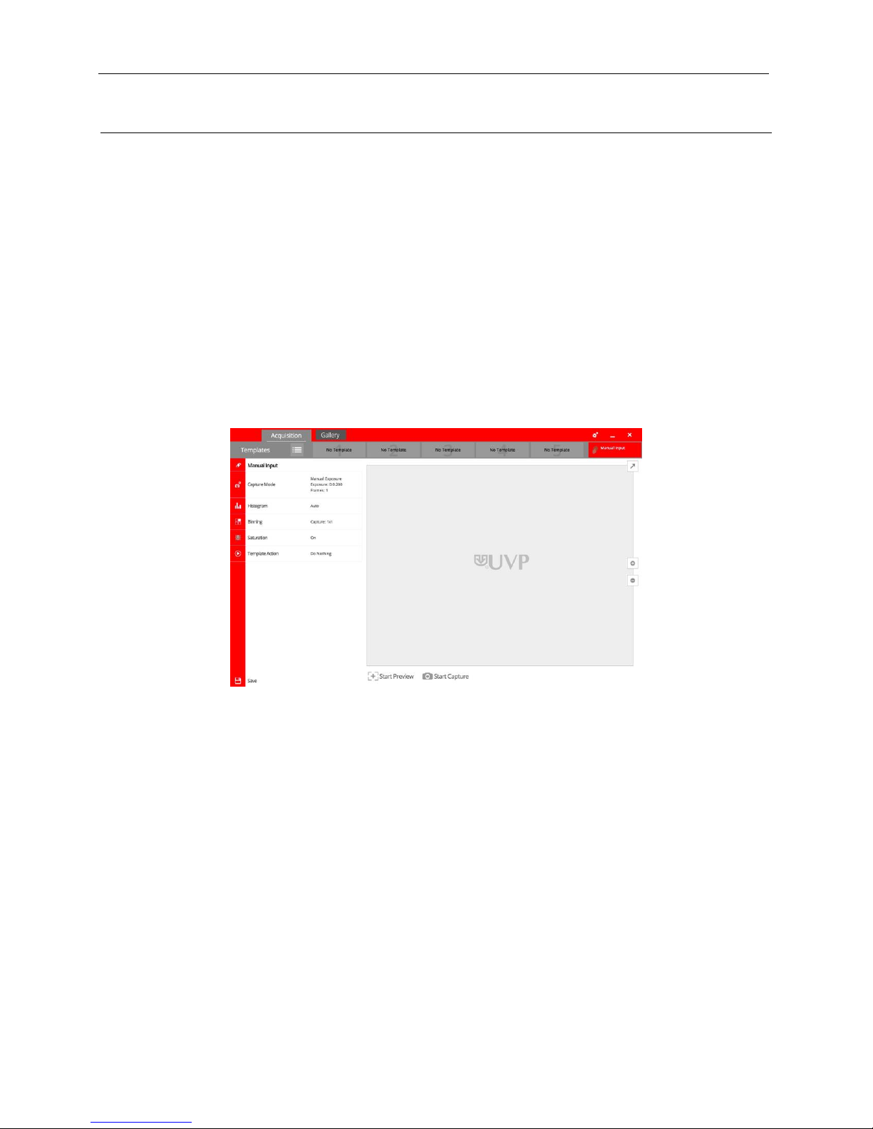
Operating the VisionWorks touch Interface
Upon startup, the internal computer will proceed through the boot-up process. When complete, the Windows
desktop will appear. The software interface, similar to the one below, will open automatically shortly
thereafter.
To exit the software interface, press either the close (X) or minimize (_) buttons at the top right corner of the
software window.
Refer to Touch Screen Interface in this manual for further instructions on using the software.
Using the Transilluminator
Once the BioDoc-It2 darkroom is plugged in to a power outlet, power is supplied to all components. This
includes the jumper cable that supplies power to the transilluminator.
To use the transilluminator:
1. Open the darkroom door and place the main power switch located on the front of the transilluminator in
the ON (I) position. (Note: It is recommended to always leave this power switch in the ON (I) position.)
2. Use the rotary knob on the front of the transilluminator to select from the available lighting wavelengths
or intensities (transilluminator settings vary by model).
3. Locate the UV power button on the front of the BioDoc-It2 system, to the right of the touch screen. Press
this switch until it glows green. The transillumination is now active.
4. Press the switch again to turn off the transilluminator.
81-0358-01 Rev E
Page 10

BioDoc-It2 Imaging System 10
Refer to the transilluminator manual for additional instructions on using the transilluminator.
Note: The BioDoc-It2 integrates a UV interlock switch which will inactivate the UV transilluminator when the
main darkroom door is open. This switch is located on the upper right corner of the darkroom door opening
and is only accessible when the main door is open.
Using the Epi (Overhead) White Light
1. Locate the White power button on the front of the BioDoc-It2 system, to the right of the touch screen.
Press this switch until it glows green. The epi (overhead) white light is now active.
2. Press the switch again to turn off the epi (overhead) white light.
Using the UV Gel Viewer Window
The UV Gel Viewer Window, built into the main darkroom door, allows users to view the interior of the
darkroom without opening the main door. The window glass is UV blocking while providing a clear view to
the transilluminator surface for sample viewing.
To open the window cover, pull down on the metal tab. The cover will pop open. To close the cover, pivot it
up until it reengages with the two small magnets.
NOTE: Close the UV Gel Viewer Window prior to capturing light-sensitive images.
Image Focusing
Prior to capturing an image, prepare the image focus as follows:
1. Remove the blue protective film from the Fluorescent Focus Target (see the “Fluorescent Focus
Target” section of this manual for more information).
2. Turn on the transilluminator and place the Target on the transilluminator surface.
3. Using the VisionWorks touch, press Start Preview to begin viewing the sample within the system.
Adjust the focus, zoom and aperture controls using the Focus, Zoom and Aperture rings on the
camera lens until an ideal image is visible.
Refer to the Touch Screen Interface section in this manual for further instructions on using the software.
Image Zooming
The BioDoc-It2 is equipped with an optical zoom lens, meaning that the system uses the lens’ optics to make
the sample appear closer/larger on the screen. Optical zoom is adjusted using the Zoom ring on the camera
lens.
However, it may be desirable to use digital zooming to move in closer on the image. Digital zoom enlarges a
portion of the image, simulating optical zoom. Thus, the camera crops a portion of the image and enlarges
the cropped portion to fill the imaging area on the screen.
To use digital zoom functionality:
1. With a preview or captured image on the screen, use the “+” and “–” buttons located on the right side
of the image.
2. Tap and drag to move around on the zoomed-in image.
Notes regarding digital zoom operation:
The software’s digital zoom feature utilizes WYSIWYG, or “what you see is what you get,” meaning that
a zoomed preview image will result in a zoomed capture image.
A zoomed capture image will save and print as shown on the screen (WYSIWYG).
81-0358-01 Rev E
Page 11

BioDoc-It2 Imaging System 11
Refer to the Digital Zoom section of Touch Screen Interface in this manual for further information.
Touch Screen Interface
Setting User Preferences
The Settings portion of the VisionWorks touch allows the user to select preferences which are
normally set once and rarely changed. Such settings include image save format and image
save location. Access the user preferences by pressing the Settings button in the upper-right
corner of the main TS screen and selecting from the following tabs:
General Settings
Post-Processing
Saving
The following pop-up screen will appear:
General Settings Tab
Language: Use the drop-down arrow to select the desired language for the VisionWorks touch
interface. Multiple language options are available including English (US), Chinese (simplified), Turkish,
Japanese, Korean, Russian, Portuguese, Spanish and German.
Save Template: Select from Ask, Always or Never to choose whether the software should ask to save
any changes to a template, always save the changes automatically without asking, or never save the
changes automatically.
81-0358-01 Rev E
Page 12

BioDoc-It2 Imaging System 12
Post-Processing Tab
Auto Rotate: Set Auto Rotate to ON to automatically rotate the image to the desired degree upon
image capture. Note: “Auto Rotate” must be set to ON in order to rotate images during image capture,
as images cannot be rotated after capture using the VisionWorks touch.
To select the degree of image rotation, press the down arrow from the drop-down menu and choose to
rotate the image 90 degrees clockwise, 90 degrees counterclockwise, or 180 degrees (upside down).
Note: “Auto Rotate” must first be turned ON before selecting a rotation setting.
Auto Invert Image: Set Auto Invert Image to ON to automatically invert the image upon image capture.
Note: “Auto Invert Image” must be set to ON in order to invert images during image capture; captured
images can also be inverted in the Gallery view.
Noise Subtraction: Set Noise Subtraction to ON to reduce the amount of background and ambient
(“white”) noise within the image. In most circumstances, this setting should be left ON. Note: “Noise
Subtraction” must be set to ON in order to subtract noise from images during image capture, as noise
cannot be subtracted from images after capture using the VisionWorks touch.
Saving Tab
Save Format: Press the down arrow to select the desired file save format from the drop-down menu.
Save images in JPEG, TIFF, BMP or PNG file formats.
From the drop-down menu to the right of the chosen file format, choose Save Selected Format to save
the image only in the chosen format. Or, select Save Selected & Original Formats to save in both the
selected format as well as in an uncompressed TIFF format (note: two separate files will be saved using
this method).
Note: If the TIFF file format is selected and Save Selected & Original Formats is also selected, both
compressed and uncompressed TIFF files will be saved.
Save Images To: Select the location where images are to be saved. The black dot within the radio
button indicates which selection is activated.
1. Select USB to save the file to the USB drive if one is currently inserted. If a USB device is not
present, the user will be notified that a USB drive is not present when attempting to save an image.
2. Select Prompt for Location to prompt the user to select a file save location when attempting to
save an image. This setting will also allow the user to save using a custom file name.
3. Choose Select Folder to define where the file will be saved when attempting to save an image.
Select from any local or network drive by pressing the folder icon to the right of the file path display.
Note: The Select Folder radio icon must first be selected prior to defining the save location.
Auto Save After Capture: Set Auto Save After Capture to ON to automatically save the image after
capture. The image will automatically save to the location selected in Save Images To and in the format
selected in Save Format, as described above.
NOTE: If the Auto Save After Capture function is set to OFF, press the Save button in the Gallery view
to manually save an image.
Auto Print After Capture: Select ON to automatically send the captured image to the default printer
after an image is captured. If a default printer is not installed, the Windows “Printers and Faxes” dialog
will automatically appear after the image is captured. Select the desired printer in the “Printers and
Faxes” dialog box and press OK on the dialog box to print the image.
Accept or Cancel Settings
Once all Preferences settings have been made, press the Checkmark button at
the bottom of the Preferences screen to save all preferences and go back to the
81-0358-01 Rev E
Page 13

BioDoc-It2 Imaging System 13
TS Button
Function
“Off” and “On” Sliders
Throughout the TS interface, the “Off” and “On” Sliders
are used to turn settings either off or on. To toggle
between off and on, tap the Slider; the Slider will
autmatically move between the “X” (off) and the checkmark
(on).
“Acquisition” Tab
To access system acquisition settings, press to select the
Acquisition tab.
Settings
Access user preferences by pressing the Settings button
in the upper-right corner of the main TS screen. The
Settings screen allows the user to select settings which
are normally chosen once and rarely changed, such as
interface language and image save format.
See the Setting User Preferences section of this manual
for further information.
Templates
Press the Templates button to access the list of templates.
Press again to close the list of templates.
For more information on templates, see the Using
Templates section of this manual.
To view a preview of the image prior to capturing, press
the Start Preview button.
This function is active when the button’s text and pictogram
are shown in purple and read “Stop Preview”. When active,
press the button again to deactivate live preview.
Maximize Minimize
When an image preview is open, press the Maximize
button to show the image in full-screen mode.
Press the Minimize button to close full-screen.
To capture an image with user-defined settings, press the
Start Capture button. For longer exposures, the amount of
time remaining for the capture to complete will appear to
the right of the “Start Capture” button.
This function is active when the button reads “Stop
Capture” in purple lettering.
NOTE: When using the Start Capture button, if the Auto
Save After Capture function is enabled in Preferences,
the image will automatically be saved to the preset location
main TS screen. Or, press the “X” button to go back to the main TS screen without saving changes.
Identifying the Touch Screen Buttons and Functions
Using the BioDoc-It2’s built-in touch screen allows for convenient selection of all system functions, including
image capture, save and print. Following is a list of buttons on the touch screen and their individual
functions.
81-0358-01 Rev E
Page 14

BioDoc-It2 Imaging System 14
(see “Saving Tab” under Setting User Preferences in this
manual).
Slider Bar
Use the slider bar to adjust various settings. To adjust the
settings, do one of the following:
Press and drag the marker (small triangle) to the
desired position;
Touch anywhere along the gray slider bar and the
marker will automatically “snap” to that position (not
applicable to Histogram);
or
Press the “+” and “–” buttons to make fine
adjustments to the settings (not applicable to
Histogram).
Digital Zoom
To digitally zoom in on previewed or captured images, use
the Digital Zoom Buttons (“+” and “–”) located to the
right of the active image.
Tap and drag to move around on the zoomed-in image.
Capture Mode
Press the Capture Mode button to access exposure time
adjustment for live image preview and capture, as well as
to select modes for image capture.
Use the vertical slider bars and/or the “+” and “–”
buttons to make adjustments to the desired portion of the
exposure time (sec, ms or microseconds).
To adjust capture modes, select the desired mode from the
drop-down menu. Capture modes include:
Manual Exposure: Captures one (or more) images with
a pre-selected exposure time.
If desired, select the Number of Frames to be captured.
Use the “+” and “–” buttons to select the desired
number of frames.
Auto Exposure: Captures an image with an ideal
exposure time determined automatically by the system
prior to image capture. (NOTE: When using the Auto
Exposure function, any exposure time settings made by
the user prior to image capture will be changed.)
After selecting Auto Exposure, select from one of the
following image acquisition settings:
1. Best (Longer Exposure) exposes the image to the
maximum value of the histogram (65,000 gray
levels).
2. Better exposes to fill the histogram 50% so the
brightest portion of the image is at 32,000 gray
levels.
Marker
81-0358-01 Rev E
Page 15

BioDoc-It2 Imaging System 15
3. Good exposes to fill the histogram to 25% or 16,000
gray levels.
4. Minimum (Fast Exposure) exposes to fill the
histogram to 10% over background.
Histogram
Press the Histogram button to access image histogram
adjustment. Use the pointers on the vertical slider bar to
make adjustments to this setting. Slide the top marker
down to darken the image, or slide the bottom marker up to
lighten the image.
Push the “Reset” button to reset the markers to the top and
bottom of the slider bar, showing the image’s full histogram
range.
Turn Auto Adjust on to automatically adjust the image
histogram for ideal imaging results.
NOTE: Histogram settings also apply to the Gallery view,
discussed later in this manual.
Saturation Warning
Turn on Saturation Warning to provide a bright yellow or
red image overlay on oversaturated areas of the image
during Live Preview. Yellow indicates mild overexposure
while red indicates extreme overexposure.
To capture an ideally exposed image, decrease the
aperture or exposure time until the yellow or red overlay
disappears.
To activate saturation warning, press the Saturation
Warning slider until the check mark appears.
Action
Press the Template Action button to select which action
the BioDoc-It2 will take when a template is selected.
Available actions include:
Start Capture: When a template includes this Action,
all system settings will be adjusted according to the
template and then the image will automatically be
captured.
Start Preview: When a template includes this Action,
all system settings will be adjusted according to the
template and an image preview will automatically be
shown.
Do Nothing: When a template includes this Action, all
system settings will be adjusted according to the
template; no image preview or capture will occur.
Done and Save
After all template settings have been made, press the
Done (checkmark) button. Then, to save the selected
settings as a template for future use, press the Save (disk)
icon.
A window will appear prompting the user to enter a
template name using the on-screen keyboard. After the
name has been entered, press the Checkmark button to
accept the name or the “X” button to cancel.
81-0358-01 Rev E
Page 16
BioDoc-It2 Imaging System 16
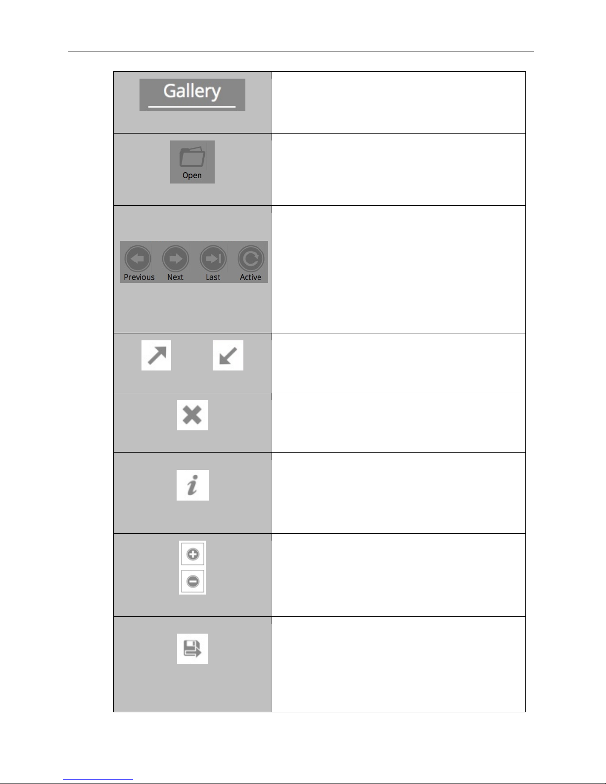
“Gallery” Tab
To access the photo gallery, press to select the Gallery
tab.
Once active, select the desired image from the top of the
Gallery screen.
Open Image
To open a previously-saved image, press the Open Image
button. Pressing this button will open the Windows
file/folder navigation screen. Select the desired file and
press Open.
Gallery Navigation
Use the Gallery Navigation buttons to navigate through
the image gallery.
When multiple “pages” of images appear in the gallery:
Press Previous to go to the previous page.
Press Next to go to the next page.
Press Last to go to the newest picture in the Gallery.
Press Active to go to the active image shown on the
main image screen.
Maximize Minimize
When an image is open in the Gallery, press the Maximize
button to show the image in full-screen mode.
Press the Minimize button to close full-screen mode.
Close
Press the Close button to the right of the image to close
the active image. If the image is unsaved, the user will be
prompted to save the image before closing.
Information
Press the “i” (Information) button to view information
pertaining to the open image, such as exposure time.
Press the “i” button again to close the image information
screen.
NOTE: Image information is only available for images
captured using the BioDoc-It2.
Digital Zoom Buttons
Use the “+” and “–” buttons located to the right of the
active image to digitally zoom in or out on Gallery images.
Tap and drag to move around on the zoomed-in image.
Save Burned
Press the Save Burned button to save the image with all
modifications (such as time stamp and histogram
modifications) embedded in the image. Or, press the Save
button to save the raw image without any modifications
embedded. Images will be saved to the location specified
in Preferences.
The file name is automatically assigned by the software as
yyyy-mm-dd_hh-mm-ss, with “yyyy-mm-dd” being the
81-0358-01 Rev E
Page 17
BioDoc-It2 Imaging System 17
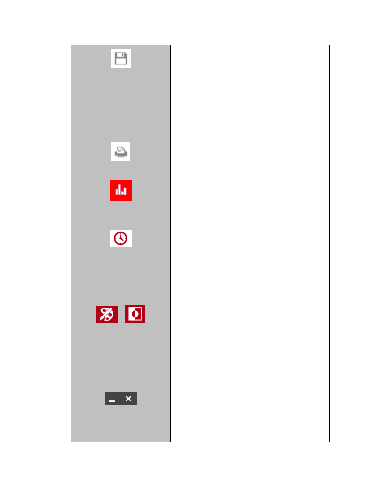
Save
date of image capture and “hh-mm-ss” being the time of
image capture.
NOTE: To manually change the file name when saving an
image, select Prompt for Location under the Saving tab
in Settings prior to saving. Then, each time the Save
button is pressed, the user will be prompted to select a file
save location and can enter a custom file name.
NOTE: If Save Selected & Original Formats is selected
in the Settings menu (described earlier in this manual) and
the Save button is pressed, both the selected and original
formats will be saved. However, if the Save Burned button
is pressed, only the selected format will be saved.
Print
Press the Print button to print the current image on the
default printer. If a default printer is not installed, pressing
the Print button will place the print request in queue.
Histogram
See the Histogram section in the Acquisition portion of
this manual for information on using the histogram in
Gallery view.
Time Stamp
To add a date stamp to the captured image, press the
Time Stamp button, then press the slider until the check
mark appears. This will add mmm/dd/yyyy hh:mm:ss to
the bottom right corner of the image.
NOTE: The time stamp is not saved to the image unless
Save Burned is selected (as described earlier in this
manual).
Pseudocolor and Invert
Press the Pseudocolor button to access a variety of
Pseudocolor options for captured images. Pseudocolor
options include in vivo, oversaturation (shows yellow to
indicate mild overexposure and red to indicate extreme
overexposure), yellow, red, green and blue. Press the
appropriate radio button to select the desired pseudocolor.
Press the Invert button to access image inversion
selection. Under Invert, touch the slider until the check
mark appears to activate image inversion.
NOTE: Pseudocolors and image inversion are not saved to
the image unless Save Burned is selected (as described
earlier in this manual).
Minimize and Close
Press the Minimize (“_”) button in the upper-right corner of
the screen to minimize VisionWorks touch.
Press the Close (“X”) button in the upper-right corner of
the screen to close VisionWorks touch. If any unsaved
images are open prior to closing VisionWorks touch, the
user will be prompted to choose one of the following:
1. Save the current image
2. Not save the current image
3. Cancel closing the software
4. Save none of the images
81-0358-01 Rev E
Page 18
BioDoc-It2 Imaging System 18
5. Save all images
The user will also be prompted to Save Selected
Format or Save Selected & Original Formats. See the
“Preferences” section of this manual for more
information.
Using Templates
The BioDoc-It2 is capable of utilizing templates to recall pre-saved systems settings for repeat experiments.
An unlimited number of templates can be saved in the system, with up to five quick-access templates
available at the top of the main system screen for easy access.
To create a template:
1. Set the various system settings as desired following the instructions shown in the Identifying the
Touch Screen Buttons and Functions section of this manual.
2. Once all desired settings have been selected, press Done at the bottom left of the screen. A
summary of all settings will be shown. Then, press Save to save the template:
a. For new templates, a popup will appear requesting for the template to be assigned a
name.
b. For existing templates, the keyboard will appear with the template name shown. The user
can then accept the current name by pressing the Checkmark button, enter a new
template name then press the Checkmark button, or press the “X” button to cancel
saving.
3. To access saved templates, press the Templates button as shown:
4. To select the quick-access templates to be shown at the top of the
TS screen, press the Templates button until the list of saved templates is shown. Then, drag the
template to the desired quick-access position.
To run a template, either:
1. Select the desired template from the Templates menu by pressing the gray check box icon to the
right of the template name, or
2. Select the template from the quick-access area.
Once the template is selected, all template settings and actions will automatically be performed on the
system.
A template is active when the template button shows white letters on a purple background. A template is
inactive when black letters are shown on a gray background.
To edit a template name, press the gray pencil icon to the right of the template name in the list of saved
templates. The template settings will be shown. Press the pencil icon in the upper-left corner of the screen to
the left of the template name. An on-screen keyboard will appear. Use the keyboard to enter the desired
template name. Press the Checkmark button to accept the revised name, or press the “X” button to cancel.
To delete a template, press the gray trash can icon to the right of the template name.
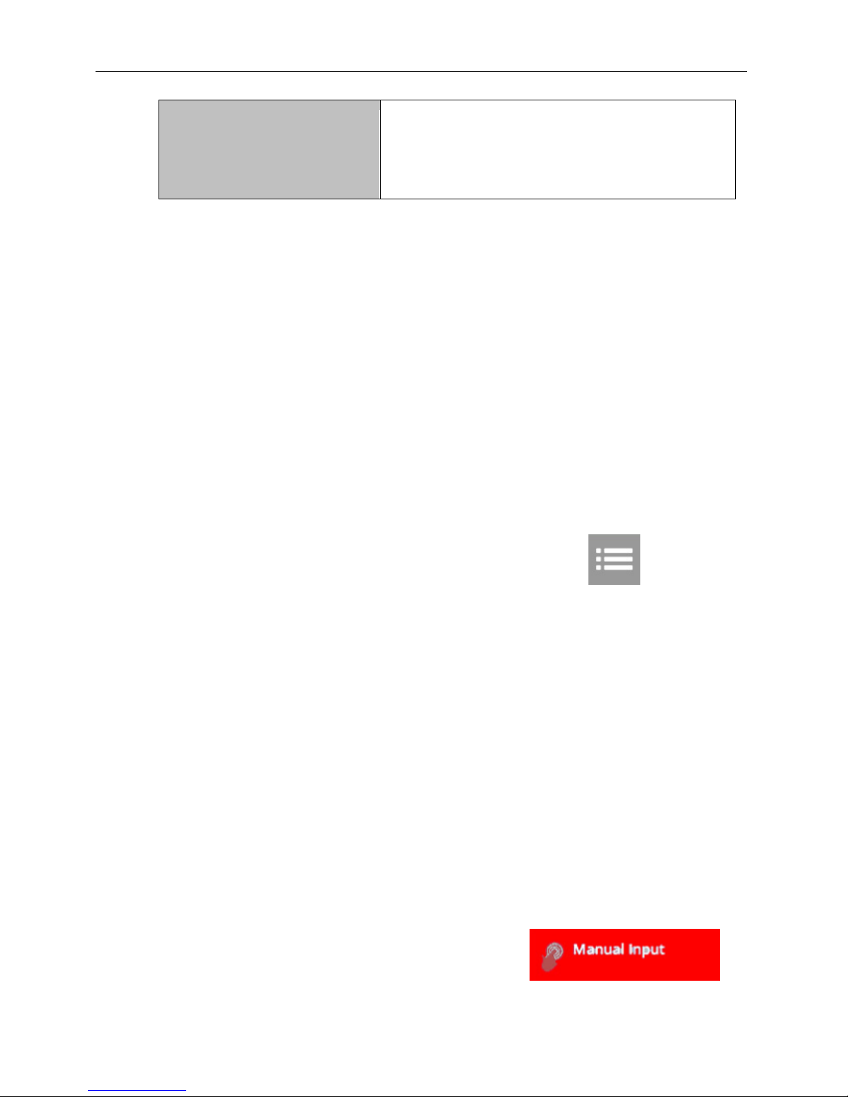
To disregard a template and enter settings and actions manually,
press the Manual Input button located at the top right of the
software.
81-0358-01 Rev E
Page 19

BioDoc-It2 Imaging System 19
Connecting to a Network
BioDoc-It2 Imaging Systems have built-in wireless networking capability. While it is fairly simple to connect
the system to a network, it is highly recommend to obtain assistance from a network administrator to ensure
that the process is completed properly.
There is also the option for connecting through wired USB-to-Ethernet.
Follow Microsoft or local standard network protocols for network configuration. To minimize the VisionWorks
touch interface and access Microsoft Windows for network configuration, press the Minimize (“_”) button in
the upper-right corner of the software.
Installing Drivers or Additional Software
In the event that additional drivers or software must be installed on the system, exit the VisionWorks touch
interface and access Microsoft Windows by pressing the Close (“X”) button located in the upper-right corner
of the main TS screen.
To install drivers or additional software, copy the software to an external storage device, open Windows
Explorer, navigate to the appropriate folder and run the desired program.
81-0358-01 Rev E
Page 20

BioDoc-It2 Imaging System 20
Service Procedures
Return Procedure
A Returned Goods Authorization (RGA) number must be obtained from UVP Customer Service before
returning any product.
Replacement Parts and Accessories
To order accessories or replacement parts for the BioDoc-It2 Imaging System, contact UVP’s offices.
Part Description Part Number
Fuses:
Fuse, 2 Amp (for transilluminator)
(M-20V, LM-20, LMS-20, M-26V, 56-0002-01 Qty 2
LM-26, LMS-26, M-26XV)
Emission Filters:
Filter, Ethidium Bromide, 50mm Square 38-0220-01
Filter, SYBR Green, 50mm Square 38-0219-01
Filter, SYBR Gold, 50mm Square 38-0221-01
Transillumination Accessories:
White Light Converter Plate, 21x26cm 38-0191-01
White Light Converter Plate, 25x26cm 38-0191-04
Visi-Blue Converter Plate, 21x26cm 38-0200-01
Visi-Blue Converter Plate, 25x26cm 38-0200-04
Gel Accessories:
Gel-Cutter 85-0002-01
Gel-Ruler 85-0003-01
Gel-Scooper 85-0006-01
Gel-Tray, small 85-0007-01
Gel-Sentry DNA Preparation Plate 97-0076-01
Fluorescent Standard Step Tablet 33-0014-02
USB-to-Ethernet Adapter 89-0380-01
Protective Equipment:
Spectacles, UV Blocking (UVC-303) 98-0002-01
Goggles, UV Blocking (UVC-503) 98-0002-02
Faceshield, UV Blocking (UVC-803) 98-0002-04
81-0358-01 Rev E
Page 21

BioDoc-It2 Imaging System 21
Troubleshooting
No Power to the Darkroom or Transilluminator
1. Recheck the main power cord connection to the BioDoc-It2 darkroom, as well as the power cables
between the darkroom and transilluminator.
2. Check the fuse located at the top rear of the unit next to the power port. A flat-head screwdriver is
required. After removing the main power cable from the darkroom, use the screwdriver to pry open
the fuseholder door located directly above the power cable connector. Pop the fuse out of the
holder by pulling the fuse down and out of the holder. Inspect the thin wire within the glass fuse to
see if there is a break in the wire. If the wire is broken, replace the fuse. If fuses are blowing
repeatedly, contact UVP Technical Support for additional troubleshooting.
Transilluminator Will Not Turn On
1. Make sure to turn ON the two transilluminator power switches and that both switches are glowing
green. One switch is on the front of the BioDoc-It2 unit and is labeled UV. The other switch is
located on the front of the transilluminator itself, directly behind the darkroom door.
If the switches do not glow green, refer to “No Power to the Darkroom or Transilluminator” above.
2. Be sure the darkroom door is completely closed. There is a UV safety Interlock switch that turns the
transilluminator off when the main darkroom door is opened.
3. Be sure the transilluminator’s power jumper cord is securely connected at both the ends.
Error Messages Appear on the Screen
1. An error message that is related to the VisionWorks touch interface or Microsoft Windows may
appear on the screen. If the message is related to Microsoft Windows, such as a reminder to
activate or update the copy of Windows, please contact your system administrator for assistance.
2. If an error message appears repeatedly and your system administrator does not recognize it as a
Microsoft Windows error, contact UVP Technical Support for further assistance.
Replacing Transilluminator Tubes
Follow these steps to replace the UV tubes in the system’s transilluminator:
1. Unplug the BioDoc-It2 from its power source. Remove all cables from the back of the unit, including
power, jumper and USB cables.
2. Lay the BioDoc-It2 on its back and remove the four rubber feet from the bottom of the system using
a Phillips head screwdriver.
3. Place the system in the upright position with the back of the system facing the user. Remove all
screws holding the back panel of the BioDoc-It2 in place, then carefully remove the back panel.
4. Carefully slide the transilluminator out of the back of the system.
5. Remove the transilluminator filter cover: Use a Phillips head screwdriver to remove the four screws
on the sides of the transilluminator, then lift the filter cover off of the unit.
6. Remove the reflectors on the left and right sides of the transilluminator: Slide the reflectors up out
of the unit.
7. Remove the UV tube: Carefully rotate the tube and slide it out of the socket. Replace with a new
tube by sliding the tube into the socket and rotating into place.
8. Insert the reflectors back into place and reattach the filter cover to the transilluminator.
9. Installation is the reverse of removal.
81-0358-01 Rev E
Page 22

BioDoc-It2 Imaging System 22
If you are in North America, South
America, East Asia or Australia:
If you are in Europe, Africa, the
Middle East of Western Asia:
Call (800) 452-6788 or (909) 946-
3197, and ask for Customer Service
during regular business days, between
7:00 am and 5:00 pm, PST.
Call +44(0) 1223-420022, and ask for
Customer Service during regular
business days between 9:00 am and
5:30 pm.
E-mail your message to:
info@uvp.com
E-mail your message to: uvp@uvp.co.uk
Fax Customer Service, and send it to
(909) 946-3597
Fax Customer Service, and send it to:
+44(0) 1223-420561
Write to: UVP, LLC 2066 W. 11th
Street, Upland, CA 91786 USA
Write to: Ultra-Violet Products Ltd
Unit 1, Trinity Hall Farm Estate, Nuffield
Road, Cambridge CB4 1TG UK
For more information, see the transilluminator manual which is included with the BioDoc-It2 or contact UVP
for assistance.
Care and Cleaning
Use only mild soap or detergent solution for cleaning the BioDoc-It2. Do NOT use oil- or petroleum-based
cleaners for the cabinet. Ensure that the system is turned OFF and unplugged during cleaning.
When cleaning the transilluminator surface, use a damp soft cloth or sponge. Never use abrasive cleaners
which can damage the UV filter surface.
Technical Support
UVP offers free lifetime technical support on all of its products and software. Should you have any questions
regarding the product’s use, operation or repair, contact UVP’s offices at the locations below, or visit
www.uvp.com.
BioDoc-It and Doc-It are registered trademarks of UVP, LLC.
2UV, 3UV and Visi-Blue are trademarks of UVP, LLC.
All other trademarks are the property of their respective owners.
81-0358-01 Rev E
 Loading...