

Page 1
1-800-547-5740 • Fax: (503) 643-6322
www.ueitest.com • email: info@ueitest.com
C75
INSTRUCTION MANUAL
Page 2
Introduction
The goal of combustion analysis is to maximize the energy obtained
from a fuel while minimizing the risk of toxic gases and additional maintenance needs. Using an electronic combustion analyzer will give you
the needed values quickly for proper equipment set-up and tuning of
combustion equipment.
Common parameters to measure are CO2 and efficiency. This analyzer
measures O2, CO and flue temperature, and then calculates those. The
rotary selector makes choosing what is displayed fast, and easy, and
you can quickly move between parameters based on your needs.
This analyzer is designed for easy use, down to these simple steps
1 Power on the analyzer
2 Select the fuel
3 Place probe in the flue and measure combustion gases
More specific information on using the analyzer is included in this user
guide, including some basics of combustion.
Maximizing CO2 and efficiency has been used as a general guide, but
UEi recommends consulting technical information from the equipment
manufacture for targeted gas values.
Features include
• Measures: Flue temperature, oxygen, carbon monoxide (CO)
• Calculates: Carbon dioxide, gross efficiency, excess air, CO air free
• Unique DMM style rotary selector
• Real time clock
• CO readings to 1 ppm
• Large 2 line back-lit display
• Infrared printer port
• User programmable header
• 16 memory positions
Safety Notes
Before using this meter, read all safety information carefully. In this
manual the word "WARNING" is used to indicate conditions or actions
that may pose physical hazards to the user. The word "CAUTION" is
used to indicate conditions or actions that may damage this instrument.
WARNING!
This analyzer extracts combustion gases that may be toxic in relatively
low concentrations. These gases are exhausted from the back of the
instrument. This instrument must only be used in well-ventilated locations. It must only be used by trained and competent persons
after due consideration of all the potential hazards.
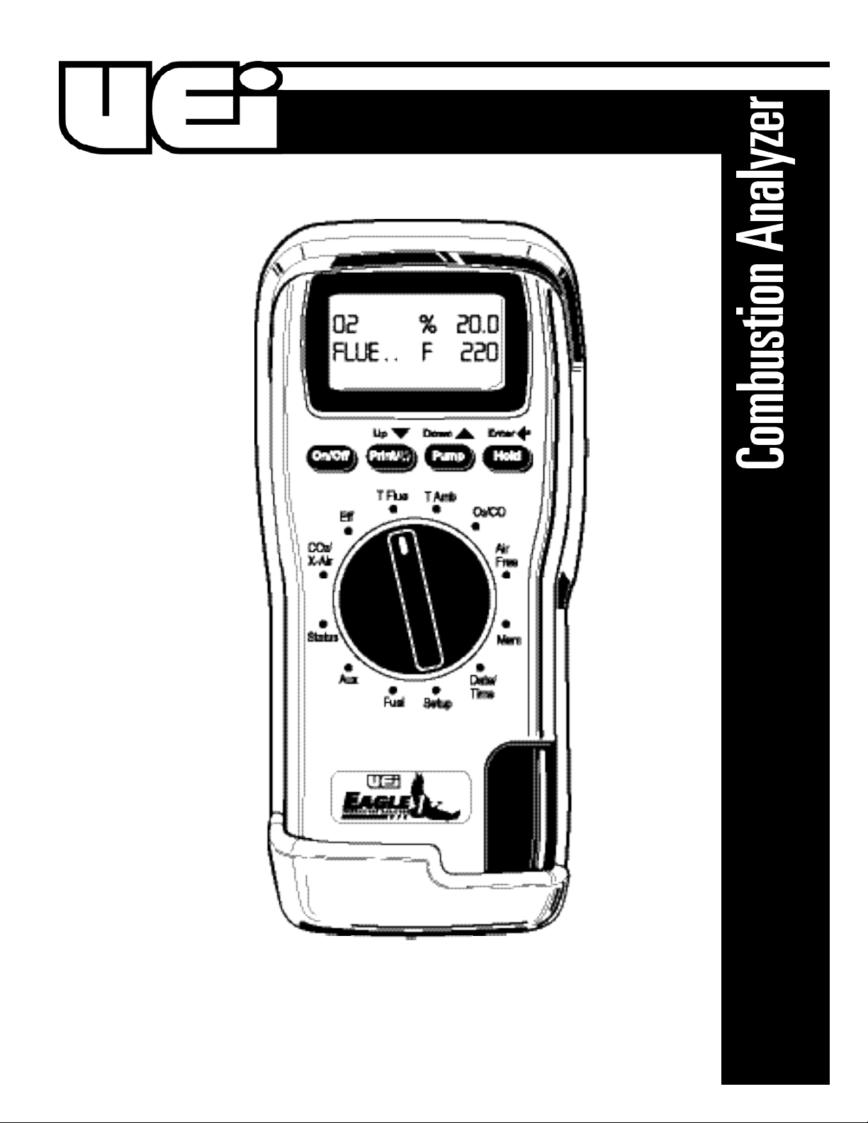
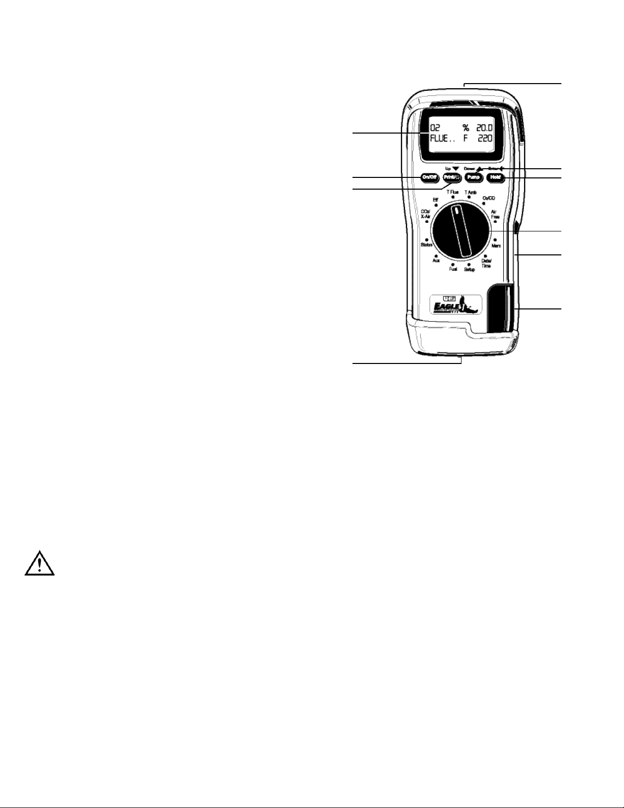
C o n t r ols and Indicators
1. Display
2. Infrared Print Emitter
3. ON/OFF: Turns analyzer ON and OFF.
4. Print/Back-Light: Print data - press briefly until “PRINTING”
appears. Back-light - press and hold to toggle back-light ON or OFF.
5. Pump: Turns pump ON and OFF. (Readings change to “ - - - -”
when the pump is OFF )
6. Hold/Store: Hold - Freezes reading on display. Entire
display flashes.
Store - press and hold for 2 seconds to store data in memory.
7. Rotary Selector
8. Particle Filter: (Inside water tra p )
9. Water Trap
10. Analyzer Connections
C75-MAN P. 1
2
1
3
4
5
6
7
8
9
10
Page 3
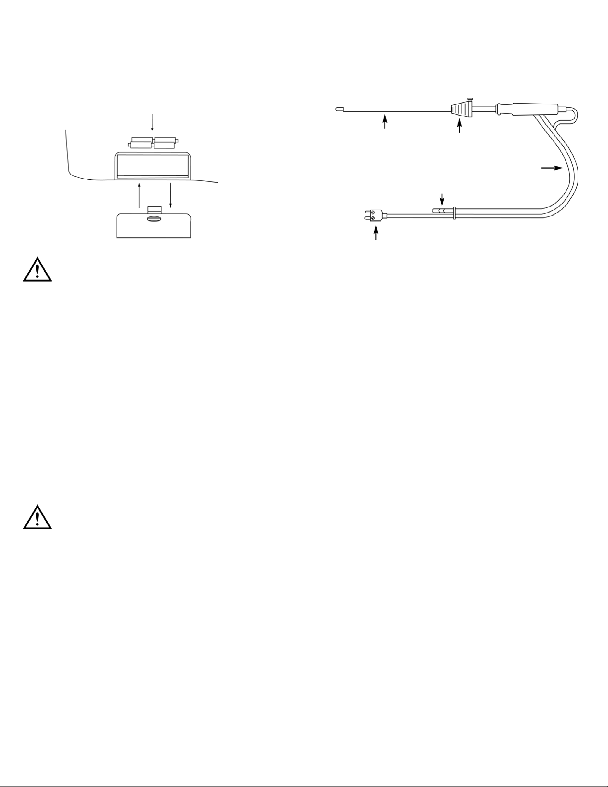
Probe Configuration
Operating Instructions
Before Use Each Time
• The particle filter is not dirty
• The water trap and probe line are empty of water
• All hose and thermocouple connections are properly made
• The flue gas probe is sampling ambient FRESH air
• The water trap is fitted correctly to the instrument
• The Flue temperature probe is connected if required to set the
inlet air temperature
NOTE: If using ambient air for combustion leave disconnected
Switch ON the instrument by pressing “ON/OFF“.
After switch-on, the analyzer will scroll through the following
information while performing a zero countdown:
• Currently Set Date
• Currently Set Time
• Remaining Battery Level
• Fuel Selected
• Model and Analyzer Firmware Level
NOTE: The count begins at 59 seconds, and will display the parameter
selected with the rotary knob when the sensors are detected as stable.
If the analyzer will not auto-zero, the sensors are in need of replacement and the unit should be returned to the authorized service center.
Battery Replacement
This meter has been designed for use with both alkaline and
rechargeable Nickel Metal Hydride (NiMH) batteries. No other types
are recommended. The analyzer is supplied with 4 “AA” size alkaline
batteries. These should be installed into the instrument as shown
below (Fig 1) and indicated on the back of the unit.
CAUTION!
Take great care when installing the batteries to observe correct polarity.
Always check the meter for operation immediately after installing
new batteries.
Using Re-Chargeable Batteries
The battery charger must only be used when NiMH batteries are fitted.
Alkaline batteries are not re-Chargeable. Attempting to recharge alkaline
batteries may result in damage to the product and may create a fire risk.
Charging
Ensure that you use the correct charger. This unit uses a 9V DC
regulated charger.
Ensure that the batteries are fitted in the correct manner, and then
charge for at least 16 hours. Subsequent charges should be overnight.
NiMH batteries may be charged at any time, even for short periods to
conduct testing.
WARNING!
Under NO c i r cumstance should you expose batteries to ex t reme heat or
f i r e as they may explode and cause injury. Always dispose of old batteries
p romptly in a manner consistent with local disposal re g u l a t i o n s .
C75-MAN P. 2
Type K-Thermometer plug
Stainless steel shaft
Depth stop cone
9 foot neoprene hose
Flue temperature probe connector
Flue gas connector
Fit probe connector to end of
tube using barbed end.
(Fig 1)
Page 4
Selecting Fuel
To set the fuel simply rotate the selector to “FUEL” then press the “U P”
or “DOWN” arrows to scroll through the choices. When the correct fuel
is displayed on the bottom line press “ENTER” to choose this fuel.
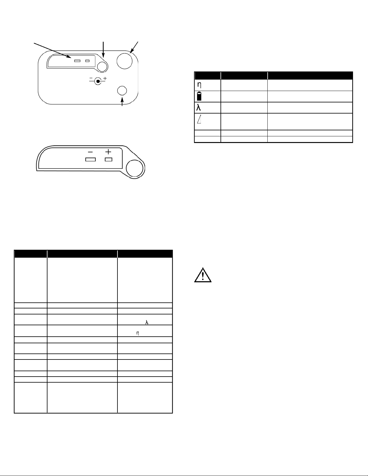
Symbol Legend
Setting Inlet Temperature
During the automatic calibration sequence the burner INLET (Ti)
temperature used in the NET temperature calculation is stored in the
analyzer. There are two methods of storing the INLET temperature.
A. Without the flue probe connected temperature inside the analyzer
is used (ambient temperature).
B. If the flue probe is connected the temperature of the probe tip is
used. This can be useful when the temperature of the air entering
the burner is different than the ambient temperature of the room.
NOTE: On ducted inlets, insert the probe tip into the inlet air during the
zero countdown. The analyzer will then store this temperature as the
ambient (inlet) for use in efficiency calculations. Do not sample flue gas
during the zero countdown.
WARNING!
If the INLET temperature is set incorrectly, then errors will be made in
the calculation of net temperature and efficiently.
Sampling the Flue Gas
Once the automatic calibration procedure has been completed and the
specific fuel has been selected (see menu options) the probe can be
inserted into the desired sampling point.
It is recommended that the sampling point be located at least two flue
diameters downstream of any bend, as close to the source as possible,
and that the probe tip is in the center of the flue. With balanced flues
and other domestic units the probe should be positioned far enough
into the flue so that no air can “back flush” into the probe.
Symbol Description Notes
Efficiency (gross) Calculated percentage efficiency based on
net temperature, O2 value and fuel selected.
Battery Level Battery level indication with percentage
remaining.
Excess Air Theoretical amount of air in excess of level
needed to completely burn fuel.
Losses Losses calculated from Oxygen and type of
fuels. Displays reading during a combustion
test. “- - - -” is displayed while in fresh air.
∆T Delta Temperature Net Te m p e r ature of Flue and Ambient (or inlet).
TF Flue Temperature Measure of Flue Temperature.
Analyzer Connections
NOTE: Take care when inserting the temperature probes as the pins are
polarized. Insert with the smaller pin (+) to the right. A view of the
sockets is shown below.
Automatic Calibration
During this sequence the analyzer pumps fresh air into the Oxygen and
CO (C75 only) sensors to allow them to be set to 20.9% and zero
respectively. See “Setting Inlet Temperature) for information on options.
Changing the Display
The parameters on the display are selected from the following using the
rotary selector knob. Certain items are available on the AUX display by
selecting through the menu.
Selector Top Line Bottom Line
Fuel Fuel Selected Fuel Indicator
(Scroll selection with the up/down • NAT GAS Natural Gas
arrows and then press the enter key • PROPANE
“HOLD” to choose • BUTANE
• L OIL Light Oil
• LPG Liquid
Petroleum Gas
• H OIL Heavy Oil
Aux User selectable line 1 User selectable line 2
Status Fuel selected Battery level
CO2 / X-Air CO2 in percentage Excess Air % (represented by
Greek Lambda )
Eff (Efficiency ) Flue Te m p e rature (TF) E f f i c i e n cy % (represented by
Greek eta )
T Flue TF (Flue temp) Net Te m p e r ature (∆T )
T Amb (Ambient) Ambient Temp (or set inlet tempera t u r e Net Te m p e r ature (∆T )
See page 7)
O 2 / CO Measured O2% Measured CO ppm
Air Fr e e Calculated value for
CO Air Free (see page 17)
Mem (Memory ) Used to view or delete stored readings
D a t e / T i m e D a t e T i m e
S e t u p Used to setup instrument Adjustment position for Time,
Date, Te m p e r ature scale,
Screen Contrast, Language,
Header, Aux selector display,
or entering Service mode.
C75-MAN P. 3
Flue (Tf) temperature
socket
Mains adapter socket Flue gas inlet
Water trap drain plug
Page 5

The probe depth stop cone provided with the instrument allows the
probe to be used in holes whose diameters range from 1/4 to 4/5 inch
(6 mm to 21 mm).
The standard probe is rated at 1112˚F (600˚C).
Where To Te s t
Boiler & Water Heaters
Boiler
Verify proper combustion:
• O2
• CO
• Stack temp
• Efficiency
Water Heater
Verify proper combustion:
• O2
• CO
• Stack temp
• Efficiency
Furnaces: 80%
80% Furnace
Verify proper combustion:
• O2
• CO
• Stack temp
• Efficiency
(Note: The following may require additional
test instruments)
Set Up
• Gas pressure
Test
• Limit switch
• Pressure switch
Verify proper combustion:
• Static duct pressure
• Temperature rise
• AC side static pressure drop
across coils
Atmospheric, Gas & Oil
Atmospheric Furnace
Verify proper combustion:
• O2
• CO
• Stack temp
• Efficiency
(Note: The following may require additional
test instruments)
Draft
Ve r i f y proper
• Temperature
• AC side static pressure drop
across coils
C75-MAN P. 4
Page 6

C75-MAN P. 5
Furnaces (
CONTINUED
): Atmospheric, Gas & Oil
Gas Furnace
Verify proper combustion:
• O2
• CO
• Stack temp
• Efficiency
(Note: The following may require additional
test instruments)
Test
• Limit switch
• Pressure switch
Set Up
• Gas pressure
Verify proper:
• Static duct pressure
• Temperature rise
• AC side static pressure drop
across coils
Oil Furnace
Verify proper combustion:
• O2
• CO
• Stack temp
• Efficiency
(Note: The following may require additional
test instruments)
Test
• Smoke
Set Up
• Over fire draft
Verify proper:
• Static duct pressure
• Temperature rise
• AC side static pressure drop
across coils
Regular Checks During Sampling
Care must be taken at all times not to exceed the analyzer’s operating
specifications. In particular ensure the following:
• Do not exceed the maximum temperature of the flue probe
• The analyzer internal temperature does not exceed normal
operating range
• DO NOT PLACE THE INSTRUMENT ON A HOT SURFACE
• The water trap is correctly attached at all times - Water condenses
in the probe line and can quickly fill the water trap when the
probe is moved - Take care and watch the water trap closely
• The particle filter is clean and does not become blocked
Normal Shutdown Sequence
WARNING!
Turning the pump off while the probe is in the flue will leave toxic
gases inside the analyzer. Once data has been printed or copied it is
advisable to purge the unit with fresh air as soon as possible. To do
this, with the probe removed from the flue, turn ON the pump. Always
allow the readings to return to zero (20.9 for O2) prior to shutting the
unit off. The meter will not switch off until the CO reading is
below 20 ppm.
WARNING!
The probe will be hot from flue gases.
Remove the probe from the flue and allow it to cool naturally. Do not
immerse the probe in water, as this will be drawn into the analyzer and
damage the pump and sensors. Once the probe is removed from the
flue and the readings have returned to ambient levels hold down
“ON/OFF“ button and switch off the analyzer.
The instrument will count down from 30 to switch off.
If you pressed “ON/OFF“ button by mistake, pressing “HOLD“ button
will return you to normal operation.
Page 7

C75-MAN P. 6
SERVICE
1. The service mode is used for repair and calibration, and
should only be entered
by authorized service facilities.
2. The firmware can be displayed by entering “2222” for
the code.
You may exit the menu at any time by rotating the selector to a
different position unless the final logical “ENTER” is pressed, no
changes are made.
Storing and Viewing Test Results
At any time during a test you may store the readings in one of the 1
memory positions. Press “HOLD” button for 2 seconds or more to
store a reading. The memory location will be displayed briefly after the
two beeps.
To review stored readings select “Mem” on the selector.
VIEW
1. Pressing “ENTER” will allow you to view stored readings.
2. Press “ “ or “ “ to select different memory positions.
Note: You may print this test at any time by pressing
“PRINT” for 2 seconds.
DEL ALL
1. Clears all values stored in memory - Confirm with “YES”
then “ENTER”.
Rotate selector to any other position to exit Memory mode.
Printing Information
Supplied as an accessory for the analyzer is an infrared thermal printer.
Read the manual supplied with the printer prior to operation.
Connection to the analyzer is detailed below:
• Infrared thermal printer - this does not require a cable to transmit
the data but uses an infrared (IR) link similar to a TV remote
control. The IR emitter is positioned on the top of the analyzer
and the bottom of the printer. Ensure they are pointing at each
other and within 3 feet, with no obstructions in the way. Data may
be lost if transmission is interrupted. Keep the analyzer pointing at
the printer until the printout has finished.
Moving Through the Menu
The options in the menu system are in the following sequence by
pressing the down arrow:
Note: The menu choices are selected using the text printed on the case
above the function keys. The three keys are “ “ increases, “ “
decrease and “ “ enter.
Set Time
1. Press “ENTE R”.
2. Use the up and down keys to select the correct time.
3. Press “ENTER” to move to the next digit.
Note: Time is displayed in military format, example 7:00 pm
is 19:00.
Date
1. Press “ENTE R”.
2. Use the up or down arrows to select the correct data.
3. Press “ENTER” to move to the next digit and then exit.
Note: Time is displayed in military format. For example 7:00 pm
is displayed 19:00.
C F
1. Press “ENTE R”.
2. Select degrees displayed in Fahrenheit or Centigrade using the
up or down keys.
3. Press “ENTER” to save and exit.
CONTRAST
1. Press “ENTE R”.
2. Select a value between 02 and 254 for desired contrast using
the up or down keys.
Note: Lower values result in a darker display.
LANGUAGE
1. Press “ENTE R”.
2. Select the desired language using the up or down keys.
3. Press “ENTER” to save and exit.
Header
1. Press up or down and “E NTER” to select desired header.
2. 2 lines of up to 16 characters will appear on the printout.
3. After entering text for header use the up or down buttons to
select “EXIT”.
AUX
1. Line 1 or Line 2.
• Press “ENTER”
• Press “ “ or “ “ to scroll through options
• Press “ENTER” again to choose the displayed option
2. Exit.
• Select “EXIT“, and then press “E NTER” to return to
the menu
Page 8

C75-MAN P. 7
Printing A Test
During combustion tests the analyzer can print data on request. With
the analyzer showing the data, briefly press the “PRINT“ button until
“PRINTING” is displayed.
The standard printout is:
NOTE: Printouts of stored
readings will also include
the TEST NO. below the
header.
SMOKE area on printout
is for adding data from
manual test.
M a i n t e n a n c e
Periodic Service
WARNING!
Repair and service of this instrument is to be performed by qualified
personnel only. Improper repair or service could result in physical
degradation of the instrument. This could alter the protection from
personal injury this meter provides to the operator. Perform only those
maintenance tasks that you are qualified to do.
These guidelines will help you attain long and reliable service from your
meter:
• Calibrate your instrument annually to ensure it meets original
performance specifications
• Keep your instrument dry. If it gets wet, wipe dry immediately.
Liquids can degrade electronic circuits
• Whenever practical, keep the instrument away from dust and
dirt that can cause premature wear
• Although your instrument is built to withstand the rigors of daily
use, it can be damaged by severe impacts. Use reasonable caution
when using and storing the meter
Cleaning
Periodically clean your instruments case using a damp cloth. DO NOT
use abrasive, flammable liquids, cleaning solvents, or strong detergents
as they may damage the finish, impair safety, or affect the reliability of
the structural components.
Emptying and Cleaning the In-line Water Trap
The in-line water trap should be checked and emptied on a regular
basis. Water vapor will condense in the probe line, which may cause the
water trap to fill suddenly if the probe is moved. Care should be taken
at all times.
Carefully remove the rubber plug from the bottom of the water-trap
housing. Dispose of the condensate in a suitable drain, care must be
taken as it could be acidic.
UEI C75
16 character header
16 character header
503 644 8723
Date: 06-26-02
Time: 14:27
Fuel NATU GAS
O2 % 20.9
CO2 % 0.0
CO* PPM 00
COaf* PPM 00
FLUE ˚F ---AMB ˚F ---NETT ˚F ----
EFF% (G) ---LOSSES** % ---XAIR % ----
SMOKE................................................................
Slide outward
Pull plug out
to drain
Page 9

C75-MAN P. 7
Below is a graph of typical combustion, showing the point of perfect
combustion and an approximate location for ideal combustion. You will
notice that by moving farther to the right on the air rich side (high
amounts of excess air), the pollutants (CO) don’t drop any further. This
is where you only lower efficiency. On the left side (fuel rich or starved
for air) you see a dramatic increase in carbon monoxide (CO), indicating that a portion of the fuel is not being converted to heat.
Combustion Efficiency Calculation
The efficiency calculation is based upon British Standards BS845.
This identifies three sources of loss associated with fuel burning:
Losses due to flue gasses: Dry Flue gas loss, moisture and
hydrogen, sensible heat of water
vapor, unburned gas
Losses due to refuse: Combustible in ash, riddlings
and dust
Other losses: Radiation, convection, conduction
other unmeasured losses
Since the fuel air mixture is never consistent there is the possibility of
unburned/partially unburned fuel passing through the flue. This is represented by the unburned carbon loss.
Losses due to combustible matter in ashes, riddlings, dust and grit,
radiation, convection and conduction are not included.
If condensate spills onto the skin or clothing, clean off immediately
using fresh water, seek medical advice if problems occur. Ensure plug is
replaced before performing combustion tests.
Changing the Particle Filter
This is a very important part of the analyzer and should be changed regularly. It prevents dust and dirt particles from entering the pump and
sensors that will cause damage. The filter MUST be changed when it
appears discolored.
Remove water-trap assembly from the analyzer as shown above.
Remove the filter and plastic holder from the housing. Discard the filter
element but keep the holder to fit to the new filter. Clean the inside of
the filter housing with a suitable soft cloth. Fit the holder onto the new
filter element and then insert into the housing. Refit the housing onto
the analyzer.
C o m b u s t i o n
Combustion Theory
In its simplest form, combustion is the combining of oxygen (O2) from
the air with hydrogen (H) and carbon (C) from the fuel to form carbon
dioxide (CO2), water (H2O) and energy (light and heat).
Perfect combustion occurs when all of the carbon and hydrogen in the
fuel unite with all of the oxygen supplied by the air. This is also referred
to as “STOICHIOMETRIC Combustion”.
In the real world perfect combustion is nearly impossible to achieve.
When tuning a combustion appliance, the goal is to come close to this
target to minimize losses and excess emissions. One method is to adjust
the amount of air supplied to the combustion area. Too little combustion air, and there will not be enough oxygen to unite with the hydrogen
and carbon. This will result in partially burnt fuel, and the creation of
carbon monoxide (CO), smoke, and lower efficiency. Too much air will
also lower efficiency because the high amount of excess air draws heat
away from the combustion area up the flue (increase in ∆T, difference
between flue temperature and ambient or inlet). If the amount of excess
air is too high, it will also move past the heat exchanger too quickly,
resulting in a lower amount of heat transferring to the target.
Insert a new filter
Rich
Lean
Page 10

The formula for K4 is based on the gross calorific value Qgr. To obtain
the loss based on net calorific value multiply by Qgr/Qnet. Since this
loss is usually small, this conversion has been ignored. This loss is
subtracted from the efficiency.
CO AIR-FREE and Converting to mg/m
3
Certain standards (ANSI Z21.1) for Carbon Monoxide are stated in
terms of air-free. Air-free refers to the concentration of CO in combustion gases undiluted with flue, or other gases containing little CO.
This value is computed using an equation that takes into account the O
2
concentration of the flue gas.
If 5% is measured (O2m) in the flue then the CO gas value will be recalculated as if 0% were measured. The equation for air-free is as follows:
COa = CO PPM x [(20.9) / (20.9 - O2m)]
Annual Re-Calibration
While the sensor has an expected life of more than two years in
normal use it is recommended that the analyzer is re-calibrated at
least annually, This is so that long-term drift on the sensor and
electronics can be eliminated. local regulations may require more
frequent re-calibration and users should check with appropriate
authorities to ensure the comply with relevant guidelines.
C50/C75-MAN P. 7
Efficiency Calculation:
Known Data - Fuel: Qgr = Gross Calorific Value (kJ/kg)
Qnet = Net Calorific Value (kJ/kg)
K1 = Constant based on Gross or net Calorific Va l u e
K1g = (255 x % Carbon in fuel)/Qgr
K1n = (255 x % Carbon in fuel)/Qnet
K2 = % max theoretical CO2
( d r y basis)
K3 = % Wet loss
H2= % Hydrogen
H2O = % Wa t e r
Measured Data: Tf = Flue Temperature
Ti = Inlet Temperature
O2m = % Oxygen in flue gas
O2r = Oxygen reference %
Calculated Data: Tnet = Net Temperature
% CO2content in flue gas
% Dry flue gas losses
% Wet losses
% Unburned carbon loss
% Efficiency
Tnet = Flue Temperature - Inlet Temperature
(or ambient)
D ry flue gas loss % = 20.9 x K1 x (Tnet)/K2 x (20.9 - O2m)
Wet loss % = 9 x H2+ H2O/Qgr x [2488 + 2.1 Tf - 4.2 Ti]
S i m p l i f i e d = [(9 x H2+ H2O)/Qgr] x 2425 x [1 + 0.001 Tnet]
Wet loss % = K3 (1 + 0.001 x Tnet)
Where K3 = [(9 x H2+ H2O)/Qgr] x 2425
Net efficiency % = 100 - dry flue gas losses
= 100 - 20.9 x K1n x (Tnet)/K2 x (20.9 - O2m)
Gross efficiency % = 100 - {dry flue gas losses + wet losses}
= 100 - {[20.9 x K1g x (Tnet)/K2 x (20.9 - O2m)]
+ [K3 x (1 + 0.001 x Tnett)]}
Excess Air = [20.9/(20.9 - O2m) - 1] x 100
CO2% = [(20.9 - O2m) x K2/20.9]
U n b u r n e d = K4 x CO/(CO + CO2) Note: CO scaled in %
fuel loss %
Where K4 = 70 for coke
= 65 for anthracite
= 63 for Bituminous coal
= 62 for coal tar fuel
= 48 for liquid petroleum fuel
= 32 for natural gas
Page 11

E l e c t r omagnetic Compatibility (EMC)
This product has been tested for compliance with the following
generic standards:
EN 50081-1, EN 50082-1
and is certified to be compliant.
The European Council Directive 89/336/EEC requires that electronic
equipment does not generate electromagnetic disturbances that exceed
defined levels and has an adequate level of immunity to enable it to be
operated as intended.
Since there are many electrical products in use that pre-date this
Directive and may emit electromagnetic radiation in excess of the
standards defined in the Directive there may be occasions where it
would be appropriate to check the analyzer prior to use. The following
procedure should be adopted.
• Go through the normal start up sequence in the location where the
equipment is to be used
• Switch on all localized electrical equipment that might be capable
of causing interference
• Check that all readings are as expected (a level of disturbance in
the readings is acceptable)
• If not, adjust the position of the instrument to minimize
interference or switch off, if possible, the offending equipment for
the duration of the test
At the time of writing this manual (July 200) Kane International Ltd is not
aware of any field based situation where such interference has ever occurred
and this advice is only given to satisfy the requirements of the Directive.
C75-MAN P. 8
Tro u b l e s h o o t i n g
The following is a list of problems that may occur on the instrument
through its operating life. If the cause of the fault is not easy to
identify then we advise you to contact UEi Technical Support line
at (800) 547-5740.
Fault Symptom Causes
• Analyzer will not power off CO reading too high, or faulty sensor.
The analyzer will not power off completely
if the CO reading is above 20 ppm, or the
sensor has an error (indicated by “----” in
the display for CO
• Oxygen too high Air leaking into probe, tubing, water trap,
• CO2too low connectors or internal to instrument,
or water trap plug missing
Oxygen cell needs replacing
• Oxygen error “----” Instrument has been stored in a
• CO sensor error “----” cold environment and is not
at normal working tempera t u r e
Oxygen cell or CO sensor needs replacing
• Display flashes Display “HOLD” is activated
B a t t e ry level is low
• Analyzer not running on AC charger not giving correct output
mains adapter
• Analyzer does not respond Particle filer blocked
to flue gas Probe or tubing blocked
Pump not working or damaged
with contaminant's
• Net temperature or efficiency Inlet (or ambient) temperature set wrong
calculation incorrect during automatic ca l i b r a t i o n
• Flue temperature readings Te m p e rature plug reversed in socket
e r r a t i c Fa u l ty connection or break in cable or plug
• X-Air, EFF, COa or CO 2 Oxygen reading is above 18 %
display (----)
• Meter just continually beeps Turn dial back to “MENU” and press
“ENTER” .
Page 12

EFF (G): Combustion efficiency calculation displayed in percentage.
Gross (G) or Net (N) can be set (see MENU). The calculation
is determined by the fuel type and uses the calculation in
British Standard BS845. The efficiency is displayed during a
combustion test, “- - - -” is displayed while in fresh air.
XA IR % : Excess air calculated from the measured oxygen and type of
fuel used. Displays reading during a combustion test. “- - - -” is
displayed while in fresh air.
A M B : Boiler air INL E T t e m p e r ature used to calculate the
NET t e m p e r a t u r e .
: Displays the approximate battery level as follow s :
• Full battery level
• B a t t e ry at 75 %
• B a t t e ry at 50 %
• B a t t e ry at 25 %
When the display flashes this, it indicates the batteries are at less than 10 %
of charge and should be replaced, readings may be affected if the analyzer
is used with low power batteries.
C75-MAN P. 9
S p e c i f i c a t i o n s
*1
Using dry gases at STP
*2
Calculated
A p p e n d i c e s
Main Display Parameters
O 2 : Oxygen reading in percentage (%).
T f : Te m p e rature is measured by the flue gas probe in Centigrade
or Fahrenheit. Will show ambient temperature after fresh air
ca l i b r ation and “- - - - ” if the flue probe is disconnected.
C O : Carbon Monoxide reading displayed in ppm (parts per
million). “- - - -” is displayed if there is a fault with the CO
sensor or the instrument has not set to zero correctly,
switch off instrument and try again.
C O a : Carbon Monoxide air-free reading referenced to an oxygen
level of 0%. Do not confuse this reading with the actual CO
reading as detailed above.
C O2: Carbon Dioxide calculation determined by the type of fuel.
This only shows a reading when a combination test is being
carried out. “- - - - ” is displayed while in fresh air.
∆T : Net temperature calculated by deducting the A MBIENT
(or INL ET) temperature from the measured FL UE
t e m p e r ature. Displays in either Centigrade (˚C) or Fahrenheit
(˚F) and will display “- - - - ” if the flue probe is not connected.
Parameter Range Resolution Accuracy
Temp Measurement
Flue temperature 1.0˚ F/C ±5˚F (2.0˚C) 32 - 1112˚F
±0.3% reading 0 - 600˚C
Inlet temperature 1˚ F/C ±1˚ F/C 32 - 212˚F
±0.3% reading 0 - 100˚C
Temp (Nett)
*2
1.0˚ F/C ±5˚F (2˚C) 32 - 1112˚F
±0.3% reading 0 - 600˚C
Gas Measurement
Oxygen 0.1% ±0.2%
*1
0 - 21%
*Carbon Monoxide 1 ppm ±10 ppm <100 ppm*10 - 1000 ppm
±5% reading
Carbon Dioxide
*2
0.1% ±0.3% reading 0 - 30%
Efficiency
*2
0.1% ±1.0% reading 0 - 99.9%
Excess Air
*2
0.1% ±0.2% 0 - 250%
Pre-programmed fuels Natural gas, Light Oil, Propane, Butane, LPG
Dimensions
Weight 1 kg. / 2.2 lb.
Handset 200mm/7.9” x 45mm/1.8” x 90mm/3.5”
Probe (L) 300mm/7.9” x (Dia) 6mm/0.25” with 200mm/7.8”
long stainless steel shaft, type K thermocouple and
3m/6ft long neoprene hose
Ambient operating +32˚ - 104˚F (0˚ - 40˚C)
10% to 90% RH non-condensing
Battery life 4 “AA” cells
range >8 hours using Alkaline “AA” cells
AC adapter (optional) Input: 110 V AC
Output: 9 V DC regulated
Page 13

Limited Warranty
The C75 is warranted to be free from defects in materials and workmanship for a period of
three years (two years on sensors) from the date of purchase. If within the warra n ty period
your instrument should become inoperative from such defects, the unit will be repaired or
replaced at UEi’s option. This warra n ty covers normal use and does not cover damage which
occurs in shipment or failure which results from alteration, tampering, accident, misuse,
abuse, neglect or improper maintenance. Batteries and consequential damage resulting from
failed batteries are not covered by warra n ty.
Any implied warranties, including but not limited to implied warranties of merchantability
and fitness for a particular purpose, are limited to the express warranty. UEi shall not be
liable for loss of use of the instrument or other incidental or consequential damages,
expenses, or economic loss, or for any claim or claims for such damage, expenses or
economic loss. A purchase receipt or other proof of original purchase date will be required
before warra n ty repairs will be rendered. Instruments out of warra n ty will be repaired (when
r e p a i r able) for a service charge. Return the unit postage paid and insured to:
1-800-547-5740 • FAX: (503) 643-6322
www.ueitest.com • Email: info@ueitest.com
This warranty gives you specific legal rights. You may also have other rights which vary from
state to state.
C75
Combustion Analyzer
Copyright © 2006 UEi C75-MAN 9/06
PLEASE
RECYCLE
 Loading...