

Page 1
C125 & C127 SENSOR CALIBRATION & REPLACEMENT
QUICK START GUIDE
Calibration Instructions;
Note: Disclaimer of Liability
These instructions are prepared for use by trade professionals familiar with gas analysis and detection,
and are familiar or have experience in calibrating gas measurement systems. They are intended to be
as complete and simple as possible to eliminate the chance for error. Certain factors related to analyzer
field recalibration are beyond the control of UEi, and the user should be aware of these factors such as
proper delivery of gas to the analyzer during calibration, the age of the calibration gas, and the accuracy of the calibration gas.
By using these instructions to recalibrate your instrument, you assume all risks and liability associated
with the measurement of carbon monoxide (CO) gas concentrations.
Indemnification
esentatives,
epr
zer, you
ate your analy
xtent permitted b
o the e
T
ee to defend, indemnify, and hold harmless, U
r
ag
ents from and against all claims and expenses, including attorneys’ fees, arising out of the use of
and ag
this material.
y applicable law, b
y using these instructions to r
Ei, its ag
encies, officers, emplo
ecalibr
yees, r
SENSOR CALIBRATION & REPLACEMENT QUICK START GUIDE .
Page 2
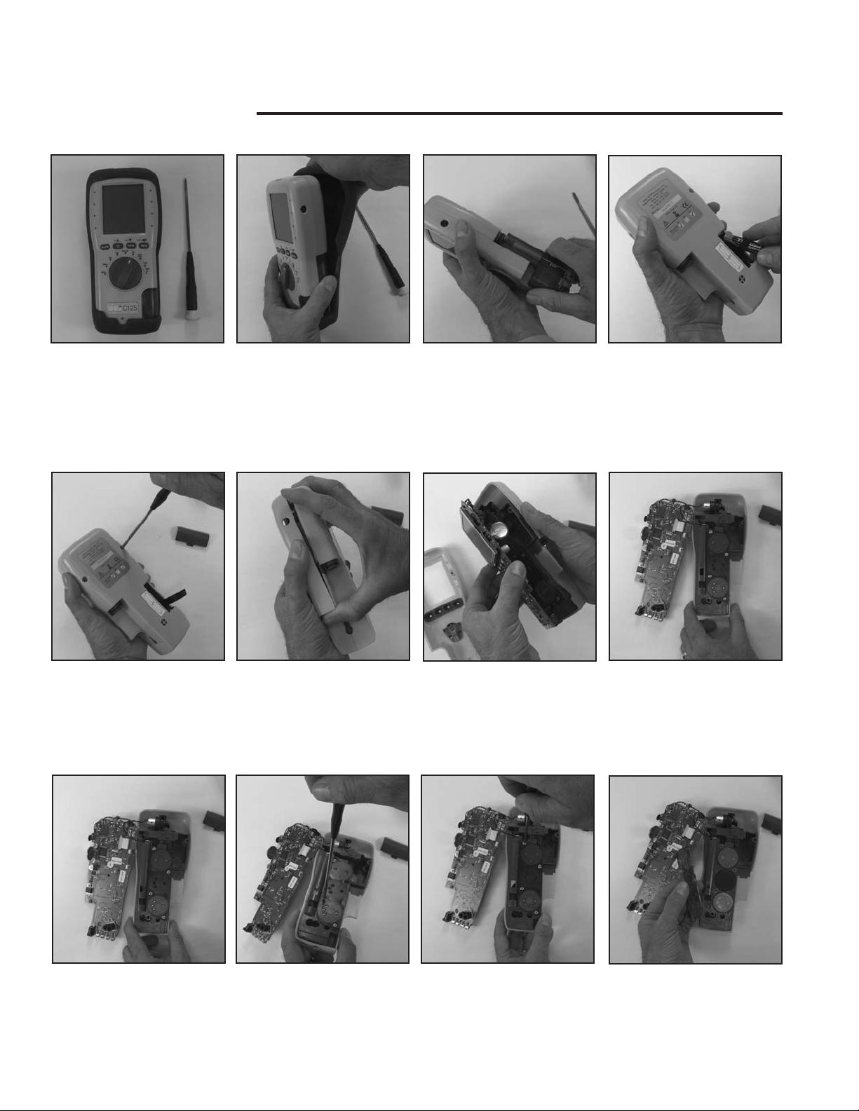
SENSOR REPLACEMENT
1. Tools required to replace the
sensor include a standard
Phillips screw driver and a
source of calibration gas.
5. Remove the two screws
securing the case halves
together.
2. Remove the protective boot
from the instrument.
6. Separate the case by gently
pressing up on the front
housing with pulling the top
apart.
3. Remove the water trap by
sliding down and then away
from the housing.
7. Lift the main circuit board up
and away from the instrument.
4. Remove the batteries.
a. Be careful of the wiring
harness that powers the pump
and connects to the battery
compartment.
8. Place the instrument on a flat
surface with the circuit board
positioned as shown.
9. Remove the four screws
holding the sensor cover
in place.
10. Remove the sensor cover.
11. Lift the sensor to be replaced
out of the manifold.
ensor located at the top is
S
a.
O2, and the bottom
position is CO.
Page 3

Note the position of the
b.
alignment pin on the O2
and pin orientation on the
CO sensors. These will only
fit into the sensor cover in
one position.
12. Install the sensor to be
replaced.
13. Reinstall sensor cover.
a. Verify that the sensor cover
is seated on the manifold
e tightening screws.
befor
14. Set circuit board back on
manifold.
a. Align sensor pins with sockets
on circuit board.
14. Join case halves together
starting at the bottom edge as
shown
15. Reinstall case screws
Page 4

GAS CALIBRATION
It is recommended to allow the sensors to stabilize a minimum of four hours before calibration.
1. Turn instrument on in fresh air
and allow to zero.
5. Select “Cal_CO”.
2. Select “Menu”.
6. Enter gas concentration.
3. Scroll to “Service”.
7. Connect Gas.
4. Enter user code “1
234
”.
8. Adjust regulator to match flow
of instrument.
a. Floating ball should be in
the middle of the second
om the bottom.
space fr
b. Note the pitch of the pump.
It should match the pitch
when drawing in ambient
air.
9. Allow to sample gas three
minutes.
a. Reading does not indicate
ppm value.
b. Slight fluctuation of display
is normal.
CANADA: 1-877-475-0648 • Fax: 604.278.8299
GLE Combustion
EA
YRIGHT © 20
COP
07 UEi.
10. Press “Enter” at the end of
3 minutes.
eading is not ppm,
Note r
and may still fluxuate slig
11. Scroll to “
press “
htly.
Exit” and then
Enter”.
USA: 1.800.547.5740 • Fax: 503.643.6322
W W W.UEiTEST.COM
Analyzers™ is a trademark of UEi. CALKIT-MAN 11/07
 Loading...