

Page 1
Homestyle
SWD452C
Stacked Washer/
Dryers
Refer to Page 6 for Model Numbers
Troubleshooting
www.comlaundry.com
Part No. 802848R2
August 2011
Page 2

Page 3

Table of
Section 1 – Safety Information ...............................................................3
Locating an Authorized Servicer...........................................................4
Contents
Section 2 – Introduction..........................................................................5
Customer Service...................................................................................5
Nameplate Location...............................................................................5
Model Identification..............................................................................6
How Your Stacked Washer/Dryer Works.............................................7
Section 3 – Troubleshooting....................................................................9
1. Washer Motor Circuit ...................................................................9
2. Troubleshooting Knocking Noise .................................................9
3. No Spin Due to Out-of-Balance Switch Wiring Problem
Starting Serial Nos. Beginning 0307...........................................10
4. Troubleshooting LEDs on Washer Inverter Controls Starting
Machine Serial No. 0911014603 ................................................11
5. No Spin (Washer)........................................................................11
6. Troubleshooting Shock Absorbers..............................................13
Section 4 – Dryer Troubleshooting ......................................................15
7. Dryer Motor Does Not Run ........................................................16
8. Dryer Stops in Cycle; Quits After the First Few Loads;
Has a Burning Smell; Cycles On Motor Thermal Protector.......18
9. Dryer Motor Runs But Cylinder Does Not Turn ........................19
10. Dryer Motor Does Not Stop .......................................................20
11. Dryer Runs Only When Door is Open........................................21
12. Dryer Heating Assembly Does Not Heat or
Burner Does Not Ignite...............................................................22
13. Igniter Does Not Glow (Gas Supply Sufficient) –
Gas Dryer Models .......................................................................24
14. Burner Ignites and Goes Out Repeatedly –
Gas Dryer Models .......................................................................25
15. Igniter Glows But Burner Does Not Ignite –
Gas Dryer Models .......................................................................26
16. Dryer Heater Assembly or Burner Shuts Off Prematurely .........27
17. Dryer Heater Assembly or Burner Repeatedly
Cycles Off On Limit Thermostat ................................................28
18. Dryer Heater Assembly or Burner Does Not Shut Off...............30
19. Clothes Do Not Dry in Dryer......................................................31
20. Timer Does Not Advance in Automatic Cycle ...........................32
21. Clothes Are Too Hot When Removed From Dryer ....................33
22. Excessive Chattering or Vibrating Noise in Dryer .....................34
23. Excessive Humming or Whistling Noise in Dryer......................35
Section 5 – Washer Control Troubleshooting .....................................37
24. Washer Error Code Listing .........................................................37
25. Washer Will Not Start – No LEDs/Lights Lit
(No response to start switch).......................................................38
© Copyright 2011, Alliance Laundry Systems LLC
All rights reserved. No part of the contents of this book may be reproduced or transmitted in any form or by any means without
the expressed written consent of the publisher.
802848 1
© Copyright, Alliance Laundry Systems LLC – DO NOT COPY or TRANSMIT
Page 4

26. Washer Will Not Start – Door Open Error
(Wash/Rinse LEDs Flashing –
Door must be closed and attempting to lock) .............................40
27. Washer Will Not Start – No Door Lock
(Door LED Flashing) ..................................................................42
28. Washer Motor Will Not Run
(Door/Final Spin LEDs Flashing)...............................................44
29. Washer Will Not Fill – No Communication Error
(Wash/Door LEDs Flashing) ......................................................46
30. Washer Overflows.......................................................................48
31. Pump Does Not Operate .............................................................50
32. Serial Communication Error
(Final Spin/Rinse LEDs Flashing) ..............................................52
33. Washer Will Not Heat – Open/Shorted Temperature Sensor
(Heating LED Flashing at End of Cycle)
(Models equipped with heater) ...................................................54
34. Washer Will Not Heat (Models equipped with heater)...............56
Section 6 – Adjustments ........................................................................59
35. Cabinet Leveling Legs ................................................................59
36. Washer Loading Door.................................................................60
37. Washer Motor Belt Tension........................................................61
38. Washer Door Catch.....................................................................62
39. Shipping Braces ..........................................................................64
40. Burner Flame (Gas Models)........................................................65
Section 7 – Dryer Test Procedures .......................................................67
41. Timer Contacts............................................................................67
42. Fabric Selector Switch ................................................................68
43. Drive Motor.................................................................................69
44. Motor Switch...............................................................................72
45. Burner System Operation............................................................74
46. Electrical Circuit To Ignition System (Gas Models) ..................75
47. Gas Valve Coils Check (Gas Models) ........................................75
48. Sensor Check (Gas Models)........................................................76
49. Igniter Check (Gas Models)........................................................76
50. Thermal Fuse (Electric Models) .................................................77
51. Heater Assembly (Electric Models)............................................77
52. Cycling or Limit Thermostat.......................................................77
53. Door Switch ................................................................................78
Section 8 – Internal Wiring of Dryer Motor Switch...........................79
2 802848
© Copyright, Alliance Laundry Systems LLC – DO NOT COPY or TRANSMIT
Page 5
Section 1
• Failure to install, maintain, and/or operate this machine according to the manufacturer’s
instructions may result in conditions which can produce serious injury, death and/or property
damage.
• Do not repair or replace any part of the machine or attempt any servicing unless specifically
recommended or published in this Service Manual and that you understand and have the
skills to carry out.
• Whenever ground wires are removed during servicing, these ground wires must be
reconnected to ensure that the machine is properly grounded and to reduce the risk of fire,
electric shock, serious injury, or death.
W284
WARNING
Safety Information
Throughout this manual and on machine decals, you will find precautionary statements (“CAUTION,”
“WARNING” and “DANGER”) followed by specific instructions. These precautions are intended for the personal
safety of the operator, user, servicer, and those maintaining the machine.
a DANGER
Danger indicates an imminently hazardous situation that, if not avoided, will cause severe personal injury or death.
WARNING
Warning indicates a hazardous situation that, if not avoided, could cause severe personal injury or death.
CAUTION
Caution indicates a hazardous situation that, if not avoided, may cause minor or moderate personal injury or property
damage.
Additional precautionary statements (“IMPORTANT” and “NOTE”) are followed by specific instructions.
IMPORTANT
The word “IMPORTANT” is used to inform the reader of specific procedures where minor machine damage will
occur if the procedure is not followed.
NOTE
The word “NOTE” is used to communicate installation, operation, maintenance or servicing information that is
important but not hazard related.
In the interest of safety, some general precautions relating to the operation of this machine follow.
802848 3
© Copyright, Alliance Laundry Systems LLC – DO NOT COPY or TRANSMIT
Page 6
Safety Information
To reduce the risk of electric shock, fire, explosion, serious injury or death:
• Disconnect all electric power to the machine and accessories before servicing.
• Close gas shut-off valve to gas dryer before servicing.
• Never start machine with any guards/panels removed.
• Whenever ground wires are removed during servicing, these ground wires must be
reconnected to ensure that the machine is properly grounded.
• Washer motor not grounded! Disconnect electric power before servicing motor.
W502
WARNING
Repairs that are made to your products by unqualified persons can result in hazards due to
improper assembly or adjustments subjecting you or the inexperienced person making such
repairs to the risk of serious injury, electrical shock or death.
W007
WARNING
If you or an unqualified person perform service on your machine, you must assume the
responsibility for any personal injury or property damage which may result. The manufacturer
will not be responsible for any injury or property damage arising from improper service and/or
service procedures.
W286
WARNING
NOTE: The WARNINGS and IMPORTANT INSTRUCTIONS appearing in this manual are not meant to
cover all possible conditions and situations that may occur. Common sense, caution and care must be
exercised when installing, maintaining or operating the machine.
Always contact your dealer, distributor, service agent or the manufacturer about any problems or conditions you do
not understand.
Locating an Authorized Servicer
Alliance Laundry Systems is not responsible for personal injury or property damage resulting from improper
service. Review all service information before beginning repairs.
Warranty service must be performed by an authorized technician, using authorized factory parts. If service is
required after the warranty expires, Alliance Laundry Systems also recommends contacting an authorized technician
and using authorized factory parts.
4 802848
© Copyright, Alliance Laundry Systems LLC – DO NOT COPY or TRANSMIT
Page 7
Section 2
SWD1199P
Nameplate
Introduction
Customer Service
If literature or replacement parts are required, contact
the source from whom the machine was purchased or
contact Alliance Laundry Systems at (920) 748-3950
for the name and address of the nearest authorized
parts distributor.
For technical assistance, call either of the numbers
listed below:
(920) 748-3121 Ripon, Wisconsin
+32 56 41 20 54 Wevelgem, Belgium
Nameplate Location
When calling or writing about your product, be sure to
mention model and serial numbers. Model and serial
numbers are located on nameplate(s) as shown.
802848 5
© Copyright, Alliance Laundry Systems LLC – DO NOT COPY or TRANSMIT
Page 8

Introduction
Model Identification
Information in this manual is applicable to these washers.
ATE50FWP431AW01 LTSA7A*N3300
ATG50FWP301AW01 LTSA7A*N4350
BTE50FSP171TW01 LTSA9A*N
BTE50FSP281CW01 LTSA9A*N1180
BTG50FSP091CW01 LTSA9A*N3000
BTG50FSP111TW01 LTSA9A*N3060
FTE50FSP301NW01 LTUA7A*N
LTE50FGP541NW23 LTUA7A*N2802
LTKA6A*N4350 LTUA9A*N
LTL50FGP541NW23 LTZA7A*N
LTSA7A*N LTZA7A*N2802
LTSA7A*N1500 LTZA9A*N
LTSA7A*N2989 LTZA9A*N0902
LTSA7A*N3000
* Add Letter To Designate Color. W – White Q – Bisque
6 802848
© Copyright, Alliance Laundry Systems LLC – DO NOT COPY or TRANSMIT
Page 9
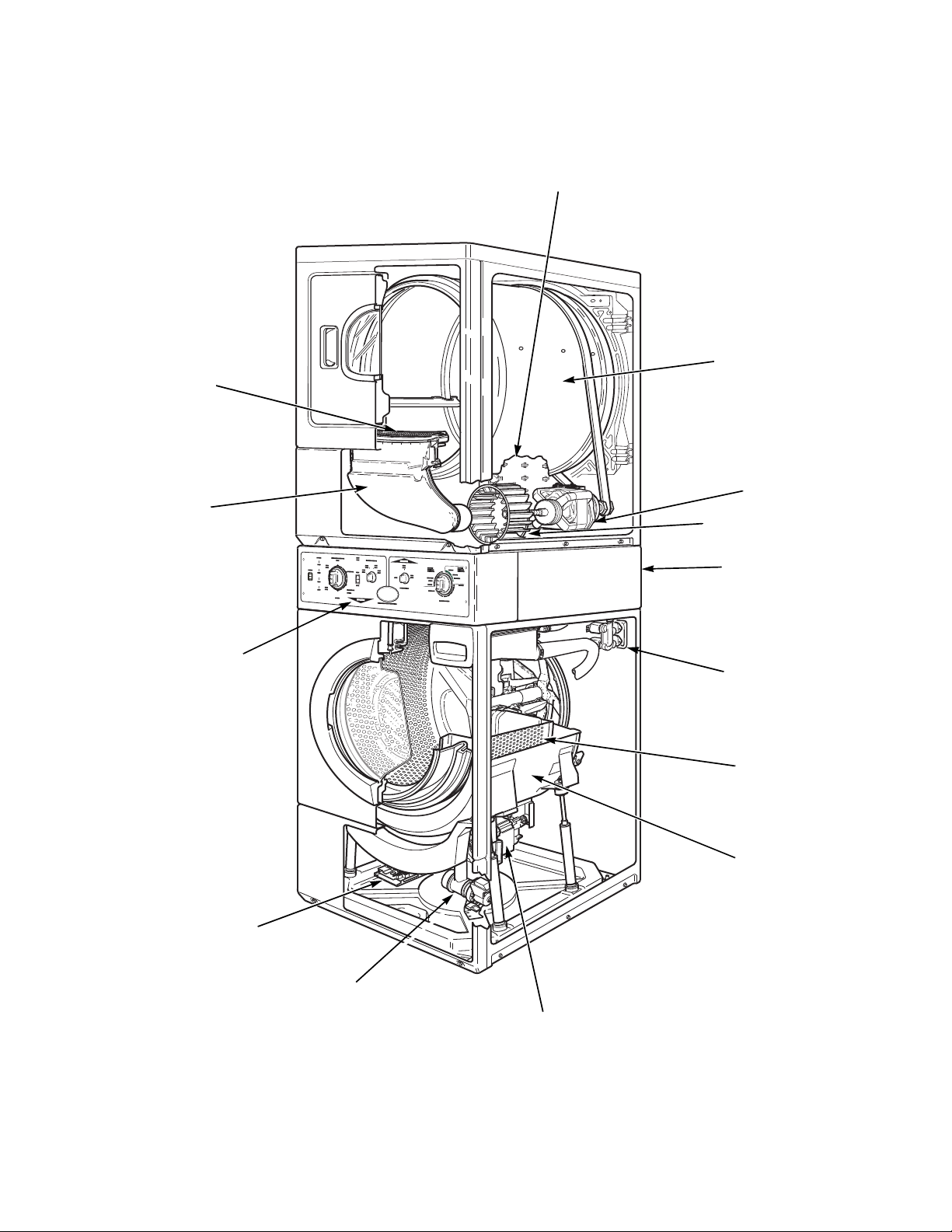
How Your Stacked Washer/Dryer Works
SWD828N
Pressure Switch
(Located inside
control cabinet)
Control
(Located inside
control cabinet)
Electric
Drain Pump
Motor
Outer
Tub
Inner
Basket
Mixing
Valve
Exhaust Fan
Inverter Control
(Mounted to base
of washer)
Motor
Cylinder
Air Duct
Lint
Filter
Heating Element
(Electric Models)
Introduction
802848 7
© Copyright, Alliance Laundry Systems LLC – DO NOT COPY or TRANSMIT
Page 10
General (Dryer)
The dryer uses heated air to dry loads of laundry.
When the motor is started, the exhaust fan pulls fresh
air in through louvers at the rear of the dryer and over
the heat source (burner flame for gas and heating
element for electric). The heated air moves through the
heater duct and into the cylinder, where it circulates
through the wet load. The air then passes through the
lint filter, air duct and exhaust fan, where it is vented to
the outdoors.
General (Washer)
This frontload washer provides some of the same
principles of operation as the typical topload washers.
It senses water level, it dispenses the desired laundry
detergent, agitates the clothes for good cleaning
action, removes the water out of the washer and spins
the clothing in preparation for the dryer.
The difference in operation is primarily the rotational
washing agitation created for the horizontal basket and
drum. This agitation tumbles the clothes in a
clockwise, pause, and counter-clockwise direction.
This reversing tumbling action provides an efficient
washing process and requires less laundry detergent
and less water.
The cycle begins by pressing the start button, which
locks the loading door. The type of cycle and water
temperature are determined by the cycle select switch
and temperature selector switch.
The inner basket starts agitating during the wash water
fill. A column of air is trapped in a pressure bulb and
hose. The air pressure continues to increase as the
inner basket fills with water until it is great enough to
activate the pressure switch which then causes the
wash fill to stop.
The regular and perm press agitate cycles tumble the
clothing in a clockwise direction for a period of 15
seconds, pauses for nine seconds and then tumbles the
clothing in a counterclockwise direction for 15
seconds. This agitation continues until the wash cycle.
The machine stops agitating and turns on the pump
which removes the wash water.
Upon completion of the wash cycle, the machine goes
into two rinse cycles. Fresh cold water is brought into
the inner basket via the mixing valve until the pressure
switch shuts off the water while agitating. The rinse
cycle consists of agitation for a predetermined amount
of time then a spin mode with the pump running while
the machine goes into a series of 4 short 500 RPM
spins.
After all the rinse cycles have been completed, the
washer goes into a final high spin cycle to extract as
much water as possible from the clothing to prepare
them for the dryer. The spin speeds and duration of
this final high spin cycle are determined by the type of
wash cycle selected (refer toTable 1 or Table 2).
NOTE: Washer may not reach 1000 RPM because
of an out-of-balance condition. Control may limit
speed to 850, 650 or 500 RPM depending on severity
of out-of-balance condition.
Models Through Serial No. 0911014602
Regular Perm Press Delicate
650
RPM
1000
RPM
3
minutes
3
minutes
Tab le 1
4
minutes
2
minutes
4
minutes
0
minutes
Models Starting Serial No. 0911014603
Regular Perm Press Delicate
500
RPM
650
RPM
1000
RPM
0
minutes
3
minutes
3
minutes
Tab le 2
0
minutes
6
minutes
0
minutes
4
minutes
0
minutes
0
minutes
Technical (Washer)
The basic operational system of this washer consists of
the control, temperature switch, the inverter control,
pressure switch, water valves, electric pump, A.C.
motor and cycle select switch.
The control performs all timing functions like the
timer in a topload washer.
The inverter control uses a speed sensor on the motor
to measure the drum RPM. Before entering any spin
step the inverter control measures the RPM of motor to
sense out-of-balance. The inverter control will try to
redistribute the clothes if an out-of-balance condition
exists; the inverter control will limit the spin speed to
several speeds depending on the severity of the out-ofbalance condition. If the out-of-balance condition is
severe enough the inverter control will limit speed to
90 RPM and will not spin.
NOTE: An additional out-of-balance switch is used
to detect any out-of-balance condition during spins.
If this switch opens during a spin step, the inverter
control immediately stops and then restarts the
spin.
8 802848
© Copyright, Alliance Laundry Systems LLC – DO NOT COPY or TRANSMIT
Page 11
1. Washer Motor Circuit
To reduce the risk of electric shock, fire, explosion, serious injury or death:
• Disconnect all electric power to the machine and accessories before servicing.
• Close gas shut-off valve to gas dryer before servicing.
• Never start machine with any guards/panels removed.
• Whenever ground wires are removed during servicing, these ground wires must be
reconnected to ensure that the machine is properly grounded.
• Washer motor not grounded! Disconnect electric power before servicing motor.
W502
WARNING
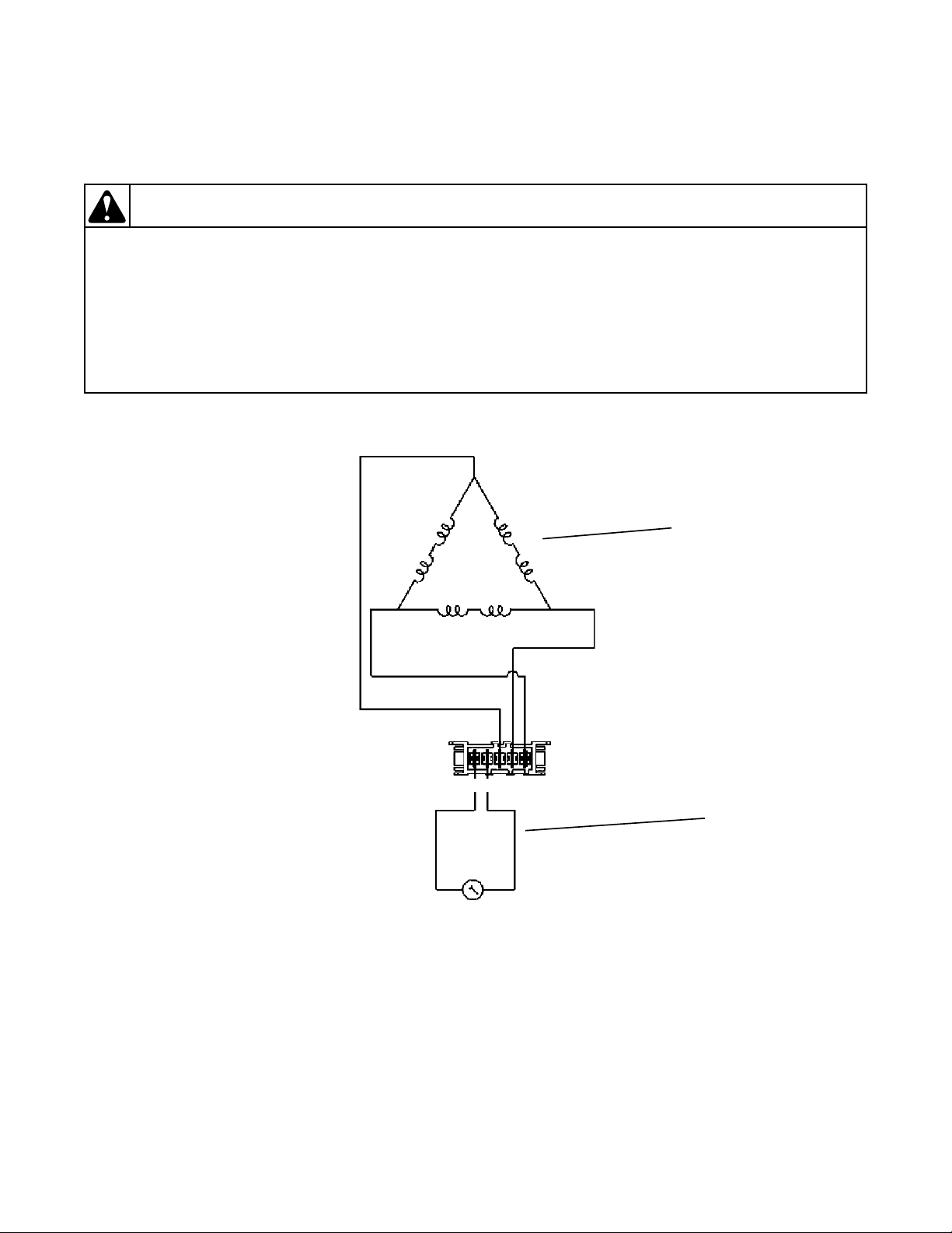
Windings
Tach. C i r c u i t
White
Gray
Red
Red
Red
5
43
21
Resistance Values:
Tachometer Circuit:
Terminals 4 –5
Approx. 115 ohms
Windings:
Terminals 1–2, 2–3, 1-3
Approx. 4.5 ohms
Section 3
Troubleshooting
2. Troubleshooting Knocking Noise
If a frontload washer produces a noise similar to a
knock on a door, it might be due to a flat spot on
the belt. The knocking sound is made when the flat
spot hits the pulley. The knocking may occur
802848 9
© Copyright, Alliance Laundry Systems LLC – DO NOT COPY or TRANSMIT
during a pulse spin and fade after reaching a
higher RPM.
To correct this condition, replace the belt.
Page 12
Troubleshooting
To reduce the risk of electric shock, fire, explosion, serious injury or death:
• Disconnect all electric power to the machine and accessories before servicing.
• Close gas shut-off valve to gas dryer before servicing.
• Never start machine with any guards/panels removed.
• Whenever ground wires are removed during servicing, these ground wires must be
reconnected to ensure that the machine is properly grounded.
• Washer motor not grounded! Disconnect electric power before servicing motor.
W502
WARNING
Wire Clamp
First Section
of Tape 4.5 In.
(11.43 cm)
From End of
Terminals
Third Section
of Tape 14 In.
(35.56 cm)
From End of
Terminals
Wire Tie
FLW1842B
45 degrees
Cut Off
Broken
Wires Here
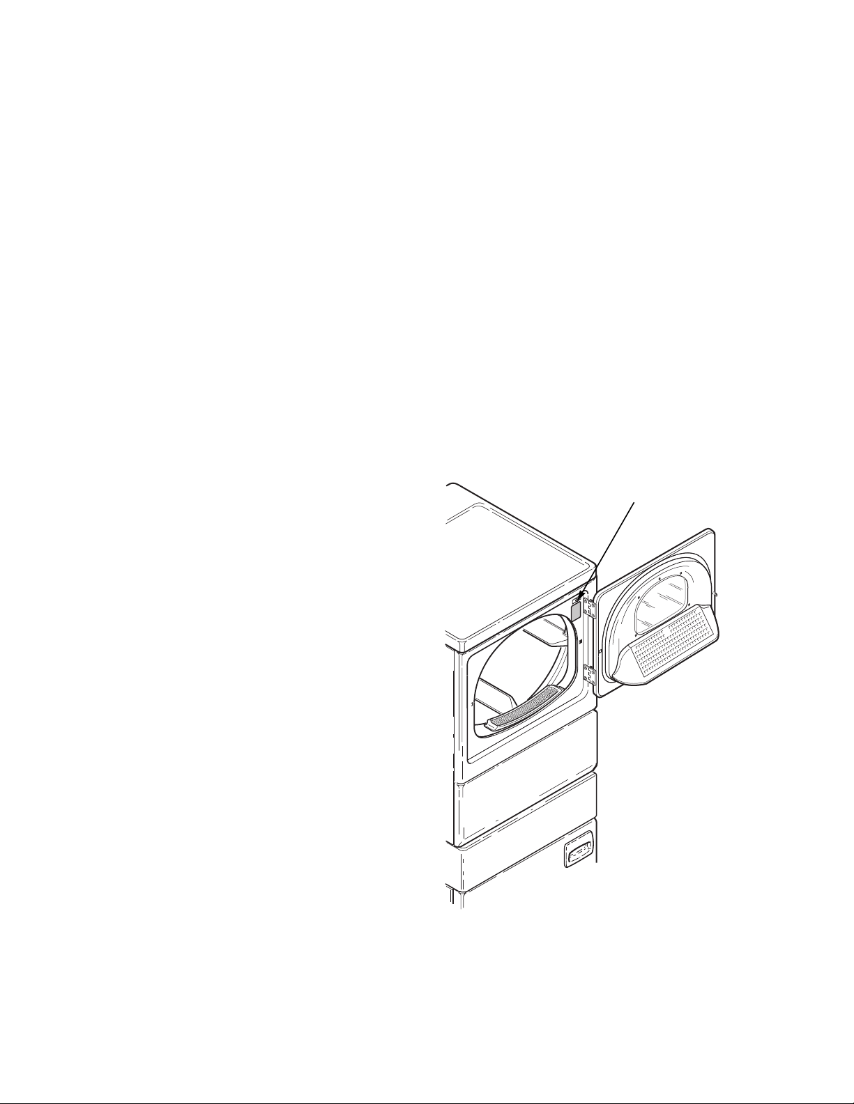
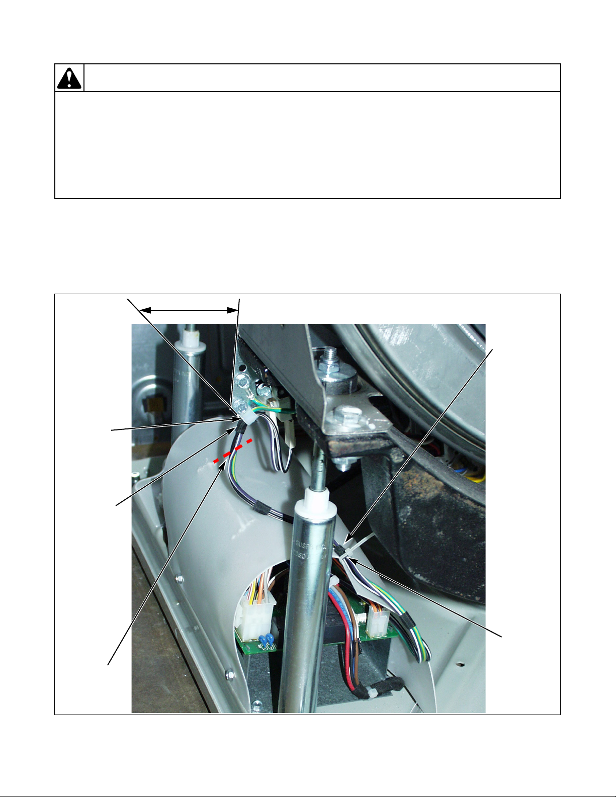
3. No Spin Due to Out-of-Balance Switch Wiring Problem Starting Serial Nos. Beginning 0307
A “no spin” condition could be the result of an open circuit in the wire harness or out-of-balance switch. First, check
that the harness is still connected to the out-of-balance switch. The out-of-balance switch is a normally closed
switch. (continued)
Figure 1
10 802848
© Copyright, Alliance Laundry Systems LLC – DO NOT COPY or TRANSMIT
Page 13
Troubleshooting
FLW1844B
LEDs
To reduce the risk of electric shock, fire, explosion, serious injury or death:
• Disconnect all electric power to the machine and accessories before servicing.
• Close gas shut-off valve to gas dryer before servicing.
• Never start machine with any guards/panels removed.
• Whenever ground wires are removed during servicing, these ground wires must be
reconnected to ensure that the machine is properly grounded.
• Washer motor not grounded! Disconnect electric power before servicing motor.
W502
WARNING
If broken wires are found at the out-of-balance switch
wire support, cut off portion of wires as shown in
Figure 1 and add new UL approved terminals.
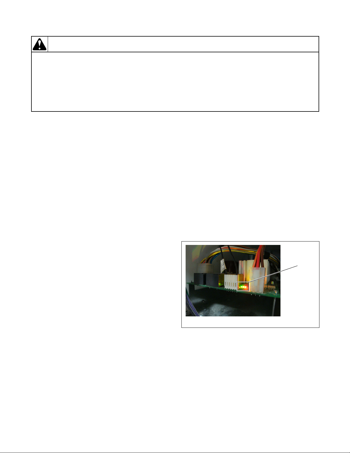
4. Troubleshooting LEDs on
Washer Inverter Controls
Starting Machine Serial No.
a. To test the electrical circuit, disconnect
electrical power to the washer.
b. Remove the “H1” connector from the inverter
control assembly.
c. Use an Ohm meter to check the black/white to
violet/white wires. Circuit should read closed.
An open reading indicates a bad switch or
wire harness problem.
d. Flex the harness at the plastic wire clamp and
test continuity. If the base wire harness has an
open circuit it MUST be replaced or the
broken wires must be repaired with UL
approved terminals.
e. After replacing or repairing the wire harness,
wrap electrical tape around wires in two
locations as indicated below and in Figure 1.
Then secure the harness wires to the original
factory locations using clamp and wire tie.
Refer to Figure 1.
(1) The plastic wire clamp should be angled
toward the switch at 45 degrees.
(2) The clamp should wrap around the first
section of tape on the harness, which should
be placed approximately 4.5 inches (11.43
cm) from end of terminals.
(3) The harness should be secured to the
inverter control shield with a wire tie.
(4) The tie should wrap around the third section
of tape on the harness, which should be
placed approximately 14 inches (35.56 cm)
from end of terminals. Refer to Figure 1.
802848 11
© Copyright, Alliance Laundry Systems LLC – DO NOT COPY or TRANSMIT
0911014603
There are three LEDs on the control to assist with
troubleshooting (refer to Figure 2):
• Green LED on constant = 5VDC power
supply present
• Green LED flashing one second on/one
second off = inverter control power up
• Red LED flashing four times/second =
inverter control is communicating with
front end control
Figure 2
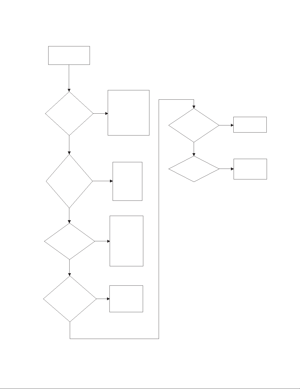
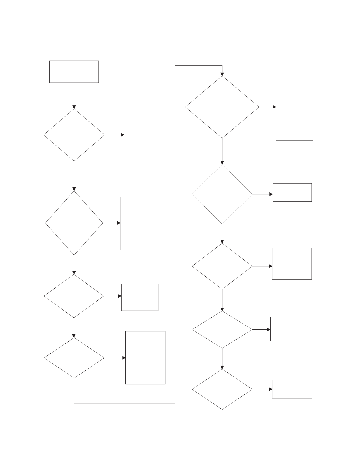
5. No Spin (Washer)
A no spin condition is not caused by intermittent
operation of the motor or motor control (inverter
assembly). DO NOT replace these components for no
spin complaints if the unit passes the following
procedure:
Page 14
Troubleshooting
No spin.
FLW1789S
Allow unit to go
through complete
final spin cycle.
Does unit spin at
high speed?
Motor and
motor control
board are
operating
properly. Do
not replace
them.
Yes
With no load, rapid
advance to final spin
or select spin only
cycle. Close door
and start washer.
BEFORE replacing
the motor control
board, conduct the
following tests.
No
Is pressure
switch or
pressure
switch wiring
inoperative?
Is load
out-of-
balance?
Unit makes three
attempts to rebalance out-ofbalance loads. If all
attempts fail, final
high speed spin is
aborted. ONLY
proper loading can
correct problem.
Yes
Is there a slow
drain, clogged
pump or
oversudsing
condition?
Pressure switch
must register an
"empty" condition
before unit will
enter spin. Clear
drain or pump.
Yes
Replace switch
and/or wiring.
No
No
Does unit
spin now?
No
Check for broken out-ofbalance switch wires.
Refer to
No Spin Due to
Out-of-Balance Switch
Wiring Problem Starting
Serial Nos. Beginning
0307
paragraph.
Yes
To reduce the risk of electric shock, fire, explosion, serious injury or death:
• Disconnect all electric power to the machine and accessories before servicing.
• Close gas shut-off valve to gas dryer before servicing.
• Never start machine with any guards/panels removed.
• Whenever ground wires are removed during servicing, these ground wires must be
reconnected to ensure that the machine is properly grounded.
• Washer motor not grounded! Disconnect electric power before servicing motor.
W502
WARNING
5. No Spin (continued)
12 802848
© Copyright, Alliance Laundry Systems LLC – DO NOT COPY or TRANSMIT
Page 15

6. Troubleshooting Shock Absorbers
To reduce the risk of electric shock, fire, explosion, serious injury or death:
• Disconnect all electric power to the machine and accessories before servicing.
• Close gas shut-off valve to gas dryer before servicing.
• Never start machine with any guards/panels removed.
• Whenever ground wires are removed during servicing, these ground wires must be
reconnected to ensure that the machine is properly grounded.
• Washer motor not grounded! Disconnect electric power before servicing motor.
W502
WARNING
A squeaking noise, oil seen on the base of the washer,
or an out-of-balance condition may mean one or more
shock absorbers need to be replaced.
To determine if there is an inoperative shock:
1. Remove front access panel.
2. Check height of rod or rod spacing above shock.
If all four shocks are uniform and have about two
inches of rod showing when basket is empty,
shocks don’t need replacing. Refer to Figure 3. If
one or more shocks is showing less than two
inches of rod, then an internal spring has broken
and all four shocks should be replaced.
3. Check base of washer below shock absorbers for
grease or oil. Shocks are not oil filled. Any oil is
from grease used internally to lubricate damper of
shock. A small amount of grease/oil on base is
normal and doesn’t indicate failure. A large
amount of grease/oil indicates a shock that might
fail soon. Do not replace shock until the internal
spring has broken as described in Step 2.
Troubleshooting
802848 13
© Copyright, Alliance Laundry Systems LLC – DO NOT COPY or TRANSMIT
Page 16
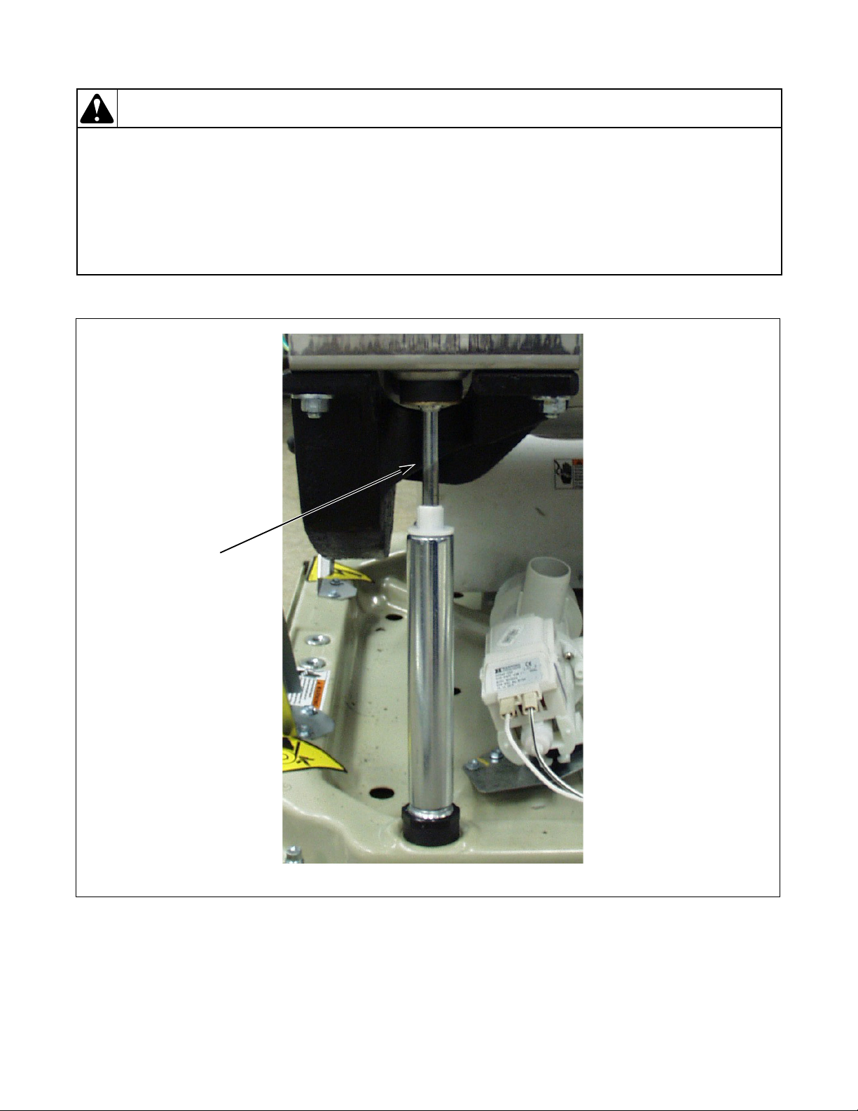
Troubleshooting
Good Shock Shows
Approximately 2
inches of Rod
FLW1845B
To reduce the risk of electric shock, fire, explosion, serious injury or death:
• Disconnect all electric power to the machine and accessories before servicing.
• Close gas shut-off valve to gas dryer before servicing.
• Never start machine with any guards/panels removed.
• Whenever ground wires are removed during servicing, these ground wires must be
reconnected to ensure that the machine is properly grounded.
• Washer motor not grounded! Disconnect electric power before servicing motor.
W502
WARNING
Figure 3
14 802848
© Copyright, Alliance Laundry Systems LLC – DO NOT COPY or TRANSMIT
Page 17

Section 4
To reduce the risk of electric shock, fire, explosion, serious injury or death:
• Disconnect all electric power to the machine and accessories before servicing.
• Close gas shut-off valve to gas dryer before servicing.
• Never start machine with any guards/panels removed.
• Whenever ground wires are removed during servicing, these ground wires must be
reconnected to ensure that the machine is properly grounded.
• Washer motor not grounded! Disconnect electric power before servicing motor.
W502
WARNING
Dryer Troubleshooting
IMPORTANT: Refer to wiring diagram for aid in
testing dryer components.
802848 15
© Copyright, Alliance Laundry Systems LLC – DO NOT COPY or TRANSMIT
Page 18
Dryer Troubleshooting
Dryer motor does not run.
Is power cord
plugged in?
Plug in cord.
Is electrical
power off or fuse
blown? Check
laundry room for
blown or loose
fuse(s), or open
circuit
breaker(s). The
dryer itself
doesn't have an
electrical fuse.
Yes
Turn power on or
replace fuse. Check
both fuses for
electric models.
Yes
Is loading
door closed?
Close door.
No
Is door switch
inoperative?
Yes
Test switch and
replace if
inoperative.
Are motor
starting
functions
inoperative,
does not
start, or motor
just hum?
Refer to
Adjustments
section to
check motor
switch and
motor
windings.
Yes
Is motor
dead,
won't run?
Refer to
Adjustments
section to
check motor
switch, motor
windings and
main windings.
Yes
SWD1706S-a
Yes
No
No
No
Is timer
improperly
set?
Reset timer
or try
another
cycle.
Is timer
inoperative?
Test timer
and
replace if
inoperative.
No
Yes
Yes
No
No
Continued on
next page.
No
7. Dryer Motor Does Not Run
16 802848
© Copyright, Alliance Laundry Systems LLC – DO NOT COPY or TRANSMIT
Page 19
7. Dryer Motor Does Not Run (continued)
SWD1706S-b
Continued from
previous page.
Is power cord
miswired?
Refer to wiring
diagram for
correct wiring.
Refer to wiring
diagram.
Is wiring
broken, loose
or incorrect?
Is motor wire
harness
connection
block loose?
Firmly press
connection
block onto
motor switch.
Remove belt
and
determine if
motor shaft
will spin.
Replace motor
if shaft is
locked up.
Is there a bind
in motor
bearing?
Is motor
centrifugal
switch sticky
or plugged
with lint?
Remove
dust or lint
and spray
with a
cleaner and
lubricant.
Wait two or three
minutes for
overload protector
to reset. If
protector cycles
repeatedly, refer
to next flowchart.
Has motor
overload
protector
cycled?
Yes
No
Yes
No
Yes
No
Yes
No
Yes
No
Yes
Dryer Troubleshooting
802848 17
© Copyright, Alliance Laundry Systems LLC – DO NOT COPY or TRANSMIT
Page 20
Dryer Troubleshooting
Dryer stops in cycle, quits after first few
loads, has burning smell or cycles on
motor thermal protector.
Is voltage
incorrect?
Refer to nameplate in
door well for correct
voltage. Refer to
Installation
Instructions
(supplied
with unit) for
electrical
requirements.
Yes
Is clothes
load too
large?
No
Remove part of
load. A normal
washer load is a
normal dryer load.
Maximum load:
dryer cylinder one
half full of wet
clothes.
Yes
Is clothes
cylinder
binding?
Check cylinder for
binding and "out of
round" condition.
Check front and rear
bulkheads for
warping. Check
support rollers for
binding. Check
cylinder seals and
glides for wear or
damage. Check for
clothes lodged
between cylinder
baffle and bulkhead.
No
Yes
Is there
broken, loose
or incorrect
wiring?
Refer to wiring
diagram.
Yes
Are motor
switch
functions
inoperative?
Refer to
Adjustments
section to
check switch
and windings.
Yes
Is there a
short in
motor
winding?
No
Is a clothes
item caught in
fan?
Check fan for
obstruction.
Yes
No
SWD1690S
Refer to
Adjustments
section to
check switch
and windings.
No
Yes
No
8. Dryer Stops in Cycle; Quits After the First Few Loads; Has a Burning Smell; Cycles On Motor Thermal Protector
18 802848
© Copyright, Alliance Laundry Systems LLC – DO NOT COPY or TRANSMIT
Page 21
9. Dryer Motor Runs But Cylinder Does Not Turn
Dryer motor runs but
cylinder does not turn.
Is motor drive
pulley loose?
Tighten pulley.
Is belt
installed on
pulley?
No
Install belt.
No
Is cylinder
belt broken?
Replace belt.
Yes
Is clothes
cylinder
binding?
No
Check cylinder for
binding and "out of
round" condition. Check
front and rear
bulkheads for warping.
Check cylinder rollers
for binding. Check
cylinder seals and
glides for wear or
damage.
Is idler lever
spring broken,
weak or
disconnected?
Replace or
reconnect
spring.
Yes
Is there oil on
cylinder?
Wipe oil from
cylinder.
Yes
Is belt "inside
out" ?
Reinstall belt
with ribbed
surface
against
cylinder.
Yes
Is idler arm
binding?
Add grease
between idler
arm and
motor mount.
Replace idler
arm and bolt
if needed.
Yes
No
Is dryer
overloaded?
Remove some
laundry from
dryer.
Yes
No
SWD1691S
Yes
Yes
Yes
No
Is the wrong
motor
installed?
Refer to parts
manual for
correct motor
part number.
Is the wrong
belt installed?
Check belt
part number
against correct
part number in
parts manual
and replace
belt if needed.
Is idler arm
bent?
Replace idler
arm.
No
No
No
Yes
Yes
Yes
Is belt routed
on wrong side
of idler lever?
Reroute belt.
No
No
No
Yes
Dryer Troubleshooting
802848 19
© Copyright, Alliance Laundry Systems LLC – DO NOT COPY or TRANSMIT
Page 22

Dryer Troubleshooting
Dryer motor does not stop.
Is wiring to
motor switch
incorrect?
Refer to wiring
diagram.
Yes
Is motor
centrifugal
switch sticky
or plugged
with lint?
No
Remove dust or lint
and spray with a
cleaner and
lubricant.
Yes
Is door switch
inoperative?
Test switch and
replace if
inoperative.
No
Yes
SWD1707S
Is timer
inoperative?
Test timer and
replace if
inoperative.
No
Yes
10. Dryer Motor Does Not Stop
20 802848
© Copyright, Alliance Laundry Systems LLC – DO NOT COPY or TRANSMIT
Page 23

11. Dryer Runs Only When Door is Open
Dryer runs only when door is
open.
Is door switch
miswired?
Rewire door
switch. Refer to
wiring diagram.
Yes
SWD1693S
Replace door switch.
No
Dryer Troubleshooting
802848 21
© Copyright, Alliance Laundry Systems LLC – DO NOT COPY or TRANSMIT
Page 24
Dryer Troubleshooting
Dryer heating assembly does not
heat or burner does not ignite.
Is exhaust
system
improper or
inadequate?
Refer to
Installation
Instructions
(supplied with
unit) for
exhaust
requirements.
Is exhaust
duct made of
plastic or thin
foil?
No
Replace with
rigid or semirigid metal
exhaust duct.
Yes
Is house fuse
blown or
circuit breaker
tripped?
Check fuses or
circuit breakers.
Yes
Is limit
thermostat
inoperative?
Test
thermostat
and replace if
inoperative.
Yes
Electric Models:
Is heater
assembly
inoperative?
Test heater
assembly
and replace
if cold
Ohms do
not read
between 9
and 10.5
Ohms.
Yes
Electric
Models: Is
thermal fuse
inoperative?
Test thermal
fuse and
replace if
inoperative.
Yes
SWD1708S-a
Yes
No
Is drive
motor switch
inoperative?
Test switch
and replace if
inoperative.
No
Yes
Continued on
next page.
No
Is temperature
selector switch
set at FLUFF,
or inoperative?
Reset or test
switch and
replace if
inoperative.
Is timer
improperly set
(set in a cool-
down period, or
a no heat
cycle)?
Reset
timer. Try
another
cycle.
No
Yes
No
No
No
Yes
No
12. Dryer Heating Assembly Does Not Heat or Burner Does Not Ignite
22 802848
© Copyright, Alliance Laundry Systems LLC – DO NOT COPY or TRANSMIT
Page 25
Dryer Troubleshooting
SWD1708S-b
Gas Models: Is
harness properly
connected to gas
controls?
Check
harness
connections
to gas valve
coils, sensor
and main
harness.
Reconnect as
required.
Test igniter
and replace if
inoperative.
Refer to
Dryer
Test
Procedures
section.
Gas Models:
Is igniter
inoperative?
Gas Models:
Is sensor
inoperative?
Test sensor
and replace if
inoperative.
Continued from
previous page.
Yes
No
Yes
No
Gas Models:
Is gas flow in
gas orifice
restricted?
Clean out gas
orifice.
Yes
Is cycling
thermostat
inoperative?
Test
thermostat
and replace if
inoperative.
Yes
Is wiring
broken, loose
or incorrect?
Refer to wiring
diagram.
Yes
Is timer
inoperative?
Test timer
and replace if
inoperative.
No
Yes
No
Gas Models:
Are gas valve
coils
inoperative?
Test coils and
replace if
inoperative.
Refer to
Dryer Test
Procedures
section.
Yes
No
No
Gas Models:
Is gas supply
insufficient?
Check gas
shut-off valve
in dryer and
main gas line
valve. Open
partially closed
gas shut-off
valve or
correct low
gas pressure.
Yes
No
No
Yes
12. Dryer Heating Assembly Does Not Heat or Burner Does Not Ignite
(continued)
802848 23
© Copyright, Alliance Laundry Systems LLC – DO NOT COPY or TRANSMIT
Page 26

Dryer Troubleshooting
Gas dryer models: Igniter
does not glow (gas supply
sufficient).
Is there power to
power leads on
valve (pink and
blue wires)?
Check
thermostats,
motor switch
and wiring.
No
Has flame
sensor failed
with contacts
open?
Yes
Replace sensor.
Yes
Is igniter broken
or open?
Replace igniter.
No
Yes
SWD1695S
13. Igniter Does Not Glow (Gas Supply Sufficient) – Gas Dryer Models
24 802848
© Copyright, Alliance Laundry Systems LLC – DO NOT COPY or TRANSMIT
Page 27

14. Burner Ignites and Goes Out Repeatedly – Gas Dryer Models
Gas dryer models: Burner ignites
and goes out repeatedly.
Is exhaust
system
improper or
inadequate?
Refer to
Installation
Instructions
(supplied with
unit) for
exhaust
requirements.
Yes
Is weather
hood flapper
restricted?
No
Is burner heat
holding sensor
contacts open?
Replace sensor
or correct gas
supply problem.
No
No
SWD1696S
Refer to
Installation
Instructions
(supplied with
unit) for
exhaust
requirements.
Yes
Is gas supply
insufficient?
Check gas supply
and pressure.
Make sure gas
shut-off valve is
turned on.
Is igniter
cracked?
Replace igniter
and bracket.
Are gas valve
coils
inoperative or
intermittent?
Check coils and
replace
appropriate coils.
Refer to
Dryer
Test Procedures
section.
No
Yes
No
Yes
Yes
Yes
Dryer Troubleshooting
802848 25
© Copyright, Alliance Laundry Systems LLC – DO NOT COPY or TRANSMIT
Page 28
Dryer Troubleshooting
Gas dryer models: Igniter glows but
burner does not ignite.
Did sensor
fail in closed
position?
Replace sensor.
Yes
Is secondary
coil or holding
coil open?
No
Is gas supply
insufficient?
Check gas
supply and
pressure. Make
sure gas shutoff valve is
turned on.
No
Yes
SWD1697S
Replace gas
valve (in
warranty) or
replace coils
(out of
warranty). Refer
to
Dryer Test
Procedures
section.
Yes
Are igniter
and bracket
improperly
installed on
burner tube
assembly?
Loosen screw and
properly position
igniter and bracket
on burner tube
assembly.
Is sensor
improperly
installed on
burner
housing?
Loosen screw
and properly
position the
sensor on the
burner housing.
No
Yes
Yes
No
15. Igniter Glows But Burner Does Not Ignite – Gas Dryer Models
26 802848
© Copyright, Alliance Laundry Systems LLC – DO NOT COPY or TRANSMIT
Page 29

16. Dryer Heater Assembly or Burner Shuts Off Prematurely
Dryer heater assembly or burner
shuts off prematurely.
Is exhaust
system
improper or
inadequate?
Refer to
Installation
Instructions
(supplied with
unit) for
exhaust
requirements.
Yes
Is weather
hood flapper
restricted?
No
Gas Models: Is
gas supply
insufficient?
Check main gas
line shut-off
valve. Open
partially closed
gas shut-off
valve or correct
low pressure.
No
Yes
SWD1709S
Refer to
Installation
Instructions
(supplied with
unit) for
exhaust
requirements.
Yes
Gas Models: Is
dryer properly
equipped for type
of gas used?
Refer to "Gas
Burner Conversion
Procedures"
supplied in gas
burner conversion
kit.
Gas Models:
Is burner
flame
improperly
adjusted?
Adjust flame.
Refer to
Adjustments
section.
Cycling off on
limit
thermostat?
Momentarily
connect a
jumper wire
across
thermostat
terminals. If
heater element
heats or burner
ignites when
jumper wire is
connected, refer
to next flowchart.
No
Yes
Yes
No
Gas Models: Is
sensor contact
closing?
Replace sensor
or adjust burner
flame (refer to
Adjustments
section).
Yes
Is cycling
thermostat
inoperative?
Test thermostat
and replace if
inoperative.
Is wiring
broken, loose
or incorrect?
Refer to wiring
diagram.
No
No
Yes
Yes
Yes
Is timer
inoperative?
Test timer and
replace if
inoperative.
No
No
Yes
No
Dryer Troubleshooting
802848 27
© Copyright, Alliance Laundry Systems LLC – DO NOT COPY or TRANSMIT
Page 30

Dryer Troubleshooting
Dryer heater assembly or burner repeatedly
cycles off on limit thermostat.
Is external exhaust
system longer or
providing greater
restriction than
recommended?
Refer to
Installation
Instructions
(supplied with
unit) for
exhaust system
requirements.
Is exhaust duct
made of plastic
or thin foil?
No
Replace with rigid
or semi-rigid metal
exhaust duct.
Yes
Is lint filter
clogged?
Clean lint
filter.
Yes
Is there lint in
internal dryer
ductwork?
No
Disassemble
dryer ductwork
and clean.
Is there lint
or other
obstruction in
external
exhaust
system?
Disassemble
and clean
exhaust
system.
Yes
Is hinged
damper on
exhaust system
weather hood
not free to
open?
Free hinged
damper or
replace
weather
hood.
Yes
Is limit
thermostat
cycling at too
low a
temperature?
Replace
thermostat.
Yes
SWD1710S-a
Yes
Yes
No
Continued on
next page.
No
No
No
No
17. Dryer Heater Assembly or Burner Repeatedly Cycles Off On Limit Thermostat
28 802848
© Copyright, Alliance Laundry Systems LLC – DO NOT COPY or TRANSMIT
Page 31

Dryer Troubleshooting
SWD1710S-b
Continued from
previous page.
Is there an air
leak at front
panel seal?
Check and
replace seal if
necessary.
Check and
replace seal(s)
if necessary.
Is there an air
leak at cylinder
seal(s)?
Is there an air
leak at blower
seal?
Check and
replace seal if
necessary.
Is there an air leak
around loading door?
(Door not sealing due
to damaged seal or
inoperative door
catch)?
Replace seal
or catch.
Yes
No
No
Yes
Yes
Yes
No
17. Dryer Heater Assembly or Burner Repeatedly Cycles Off On Limit
Thermostat (continued)
802848 29
© Copyright, Alliance Laundry Systems LLC – DO NOT COPY or TRANSMIT
Page 32

Dryer Troubleshooting
Dryer heater assembly or
burner does not shut off.
Is motor switch
inoperative?
(Must be in a
heat setting.)
Test switch and
replace if
inoperative.
Yes
Motor does
not stop?
No
Refer to
Dryer
Motor Does Not
Stop
paragraph.
Yes
Is wiring
incorrect?
Refer to wiring
diagram.
No
Yes
SWD1700S
Has heater
assembly
shorted?
Remove heater
assembly and
check for short.
No
Yes
18. Dryer Heater Assembly or Burner Does Not Shut Off
30 802848
© Copyright, Alliance Laundry Systems LLC – DO NOT COPY or TRANSMIT
Page 33

19. Clothes Do Not Dry in Dryer
Clothes do not dry in dryer.
Does heater
assembly not
heat or
burner not
ignite?
Refer to
Dryer
Heating
Assembly Does
Not Heat or
Burner Does
Not Ignite
paragraph.
Yes
Is there too
much water
in articles
being dried?
No
Is laundry
load too
large?
Remove part of
load. A normal
washer load is a
normal dryer
load. Maximum
load: Dryer
cylinder one half
full of wet
clothes.
No
Yes
SWD1711S
Remove
excess water.
Yes
Is laundry
load too
small?
Add one or two
bath towels to
load.
Is there
excessive
lint on lint
filter?
Clean lint
filter.
Is exhaust
system
improper or
inadequate?
Refer to
Installation
Instructions
(supplied with
unit) for exhaust
requirements.
No
Yes
Yes
Yes
Does heater
assembly or
burner shut off
prematurely?
Refer to
Dryer
Heater
Assembly or
Burner Shuts
Off Prematurely
paragraph.
Yes
Gas Models:
Is gas line
pressure too
high or too
low?
If Natural Gas
line pressure to
dryer exceeds 8
inch water
column
pressure, or is
lower than 4
inch water
column, ask Gas
Company to
correct.
Is belt
installed
improperly
(low RPM)?
Check for
proper
installation.
No
No
No
Yes
Yes
No
Is heat selector
switch or timer
inoperative?
Test and
replace switch
or timer if
inoperative.
No
No
Yes
Dryer Troubleshooting
802848 31
© Copyright, Alliance Laundry Systems LLC – DO NOT COPY or TRANSMIT
Page 34

Dryer Troubleshooting
Timer does not advance in
automatic cycle.
Is exhaust
system
improper or
inadequate?
Refer to
Installation
Instructions
(supplied with unit)
for exhaust
requirements.
Yes
Is cycling
thermostat
inoperative?
Test thermostat
and replace if
inoperative.
Yes
SWD1712S
Are seals
inoperative
(air leaks)?
Check and replace any
inoperative seals in the
following areas:
1. Seal between loading
door and front panel.
2. Seal between front panel
and front bulkhead.
3. Seal between blower
cover and air duct.
4. Seal between cylinder
and front or rear bulkhead.
5. Gap between air duct and
filter mounting.
Yes
Electric
Models: Is
resistor
inoperative?
Test resistor
and replace if
inoperative.
Heater
assembly
does not heat
or burner does
not ignite?
Refer to
Dryer
Heating
Assembly Does
Not Heat or
Burner Does
Not Ignite
paragraph.
Heater assembly
or burner cycles
off prematurely?
Refer to
Dryer
Heater
Assembly or
Burner Shuts
Off Prematurely
paragraph.
Is large
load
drying?
Timer will not
advance until
the load is
almost dry.
Is wiring
broken,
loose or
incorrect?
Refer to wiring
diagram.
Is timer
motor
inoperative?
Select a drying
cycle and activate
start switch. Rotate
timer knob until
signal sounds.
Release timer
knob. Signal should
stop within ten
minutes. If not,
replace timer.
No
Yes
No
Yes
No
Yes
No
No
Yes
No
Yes
No
Yes
No
20. Timer Does Not Advance in Automatic Cycle
32 802848
© Copyright, Alliance Laundry Systems LLC – DO NOT COPY or TRANSMIT
Page 35

21. Clothes Are Too Hot When Removed From Dryer
Clothes are too hot when
removed from dryer.
Is exhaust
system
improper or
inadequate?
Refer to
Installation
Instructions
(supplied with unit)
for exhaust
requirements.
Yes
Were clothes
removed from
dryer before
cycle has
completed?
No
Allow the dryer to
complete the
cycle through the
cool-down to the
OFF position.
Yes
Is cycling
thermostat
inoperative?
Test cycling
thermostat and
replace if
inoperative.
No
Yes
SWD1713S
Are seals
inoperative
(air leaks)?
Check and replace any inoperative
seals in the following areas:
1. Seal between loading door and
front panel.
2. Seal between front panel and
front bulkhead.
3. Seal between blower cover and
air duct.
4. Seal between cylinder and front
or rear bulkhead.
5. Gap between air duct and filter
mounting.
Yes
Is timer
inoperative
(not allowing
cool-down)?
Test timer and
replace if
inoperative.
No
Yes
No
Dryer Troubleshooting
802848 33
© Copyright, Alliance Laundry Systems LLC – DO NOT COPY or TRANSMIT
Page 36

Dryer Troubleshooting
Excessive chattering or
vibrating noise in dryer.
Is idler spring
inoperative?
Remove lower access panel. Set
dryer to normal cycle and allow it
to heat to operating temperature.
If the belt vibrates as it rotates
around the cylinder, the idler
arm is making the noise. Replace
the idler spring.
Yes
SWD1703S
Check blower fan
for missing or
cracked fan blades.
No
22. Excessive Chattering or Vibrating Noise in Dryer
34 802848
© Copyright, Alliance Laundry Systems LLC – DO NOT COPY or TRANSMIT
Page 37

23. Excessive Humming or Whistling Noise in Dryer
Excessive humming or
whistling noise in dryer.
Is blower
housing
inoperative?
If the abnormal operating noise is
loudest at the vent exit, the
problem is originating from the
blower housing. Replace the
current housing and cover.
Yes
SWD1704S
Check blower fan
for missing or
cracked fan blades.
No
Dryer Troubleshooting
802848 35
© Copyright, Alliance Laundry Systems LLC – DO NOT COPY or TRANSMIT
Page 38

Notes
36 802848
© Copyright, Alliance Laundry Systems LLC – DO NOT COPY or TRANSMIT
Page 39
Section 5
To reduce the risk of electric shock, fire, explosion, serious injury or death:
• Disconnect all electric power to the machine and accessories before servicing.
• Close gas shut-off valve to gas dryer before servicing.
• Never start machine with any guards/panels removed.
• Whenever ground wires are removed during servicing, these ground wires must be
reconnected to ensure that the machine is properly grounded.
• Washer motor not grounded! Disconnect electric power before servicing motor.
W502
WARNING
Washer Control Troubleshooting
24. Washer Error Code Listing
Error Conditions
If any of the following errors occur, the control enters Error Mode. For all fatal errors, the control will
terminate the current cycle, turn off all outputs, and flash two LEDs one second on/one second off to indicate
the error.
Motor Failure
Error.
Fill
Error.
Door Open
Error.
Door Lock/Unlock
Error.
SPI Communications
Error.
If the control receives the motor failure signal from the motor control, the control will enter
Error Mode. The control will turn off all outputs and flash the DOOR and FINAL SPIN LEDs
one second on/one second off to indicate a motor failure error. This is a fatal error. The
machine must be unpowered to clear this error.
If the control receives no full input from the pressure switch indicating the cylinder is full
within 30 minutes of starting the fill, the control will enter Error Mode. The control will turn
off all outputs and flash the WASH and DOOR LEDs one second on/one second off to indicate
a fill error. This is a fatal error. The machine must be unpowered to clear this error.
If the control senses the door open during Run Mode, the control will enter Error Mode. The
control will turn off all outputs and flash the WASH and RINSE LEDs one second on/one
second off to indicate a door open error. This is a fatal error. The machine must be unpowered
to clear this error.
If the door doesn’t lock in 15 seconds in Door Locking Mode or the door doesn’t unlock in 3
minutes in Door Unlocking Mode, the control will enter Door Lock Error Mode. The control
will turn off all outputs and flash the DOOR LED one second on/one second off to indicate a
door lock/unlock error.
To clear this error in Door Locked Mode the door must either open or lock. If the door locks,
the cycle will start normally. If the door opens, the control will revert back to Start Mode.
To clear this error in Door Unlocking Mode the door must unlock or open. If the door unlocks
or opens, the control will enter End of Cycle Mode.
This error occurs when there is a problem with communications between the front-end control
and the motor control. The control will turn off all outputs and flash the FINAL SPIN and
RINSE LEDs one second on/one second off to indicate an SPI communications error. This is
a fatal error. The machine must be powered down at this point.
Open/Shorted
Temperature
Sensor Error
(Models equipped
with heater)
802848 37
Any time the control senses a temperature less than 32°F (0°C) or greater than 212°F
(100°C) while heating, the control will turn off the heater output and not attempt to heat.
The control will continue and finish the cycle normally. At the end of the cycle the
control will flash the HEATING LED one-second on/one second off to indicate an open/
shorted temperature sensor error. This error will be cleared when the door is opened at
the end of the cycle.
© Copyright, Alliance Laundry Systems LLC – DO NOT COPY or TRANSMIT
Page 40

Washer Control Troubleshooting
Is there
220-240 VAC
(or 120 Volts)*
to control
transformer?
(2)
(3)
No
Yes
Yes
Is there
continuity across
terminals "H9-3" to "H9-7"
on the machine control when
the start switch is
depressed?
Replace machine
control.
*Refer to machine serial plate
for correct voltage.
No
Yes
(1)
Is there 24 VAC
from "H1-1" to "H1-3"
on the machine control ?
Replace
transformer.
Check wiring
to transformer.
No
Correct wiring
to and/or replace
start switch.
(4)
Is the
configuration
header plugged
into "H7"?
No
Yes
Correct wiring
on "H7"
configuration plug.
FLW1727S
25. Washer Will Not Start – No LEDs/Lights Lit (No response to start switch)
38 802848
© Copyright, Alliance Laundry Systems LLC – DO NOT COPY or TRANSMIT
Page 41

Washer Control Troubleshooting
220-240 VAC (or 120 VAC) 50/60Hz (SEE MACHINE SERIAL PLATE)
3
2
1
4
Washer Will Not Start – No LEDs/Lights Lit (No response to start switch)
802848 39
© Copyright, Alliance Laundry Systems LLC – DO NOT COPY or TRANSMIT
Page 42

Washer Control Troubleshooting
26. Washer Will Not Start – Door Open Error (Wash/Rinse LEDs Flashing – Door must be closed and attempting to lock)
(1)
Is there
220-240 VAC (or
120 Volts)* across
"H4-5" to "H6-5" on
the machine
control?
No
(2)
Is there
220-240 VAC (or
120 Volts)* from the
RED wire on door
lock assembly
to neutral?
Yes
Yes
Replace machine
control.
Replace door
lock assembly.
No
(3)
Is there
220-240 VAC (or
120 Volts)* from the
BLK wire on the
door switch to
neutral?
No
Correct wiring
to the door
switch.
*Refer to machine serial plate
for correct voltage.
Yes
Replace the
door switch.
FLW1770S
40 802848
© Copyright, Alliance Laundry Systems LLC – DO NOT COPY or TRANSMIT
Page 43

Washer Control Troubleshooting
220-240 VAC (or 120 VAC) 50/60Hz (SEE MACHINE SERIAL PLATE)
1
2
3
Washer Will Not Start – Door Open Error (Wash/Rinse LEDs Flashing – Door must be
closed and attempting to lock)
802848 41
© Copyright, Alliance Laundry Systems LLC – DO NOT COPY or TRANSMIT
Page 44

Washer Control Troubleshooting
27. Washer Will Not Start – No Door Lock (Door LED Flashing)
(1)
Is there
Is the
"Wash" light
lit?
Yes
(2)
Is there
220-240 VAC (or
120 Volts)* at machine
control terminals
"H4-5" to "H6-5"?
Yes
No No
No
24 VAC from
"H1-1" to "H1-3"
on the machine
control?
Check secondary door
switch, door strike
adjustment, and/or wiring.
Replace door lock if
necessary.
Replace
transformer.
(3)
Is there
220-240 VAC (or
120 Volts)* at machine
control terminals
"H4-4" to "H6-5"?
Yes
(4)
Is there
220-240 VAC (or
120 Volts)* at the door
lock between the WHT/RED
and the PNK/BLK
wires?
Yes
Replace door
lock assembly.
*Refer to machine serial plate
for correct voltage.
No
No
Replace machine
control.
Correct wiring
between machine
control and door
lock assembly.
FLW1729S
42 802848
© Copyright, Alliance Laundry Systems LLC – DO NOT COPY or TRANSMIT
Page 45

Washer Control Troubleshooting
220-240 VAC (or 120 VAC) 50/60Hz (SEE MACHINE SERIAL PLATE)
1
3
4
2
Washer Will Not Start – No Door Lock (Door LED Flashing)
802848 43
© Copyright, Alliance Laundry Systems LLC – DO NOT COPY or TRANSMIT
Page 46

Washer Control Troubleshooting
(1)
No
Is there
continuity between
motor terminals?
Refer to values
at right.
Yes
Replace motor
control.
Replace motor.
FLW1712S
Motor Resistance Values:
Tach. Circuit: Approx. 115 ohms (Terminals 4-5)
Windings: Approx. 4 - 5 ohms (Terminals 1-2, 1-3, 2-3)
28. Washer Motor Will Not Run (Door/Final Spin LEDs Flashing)
44 802848
© Copyright, Alliance Laundry Systems LLC – DO NOT COPY or TRANSMIT
Page 47

Washer Control Troubleshooting
220-240 VAC (or 120 VAC) 50/60Hz (SEE MACHINE SERIAL PLATE)
1
Motor Will Not Run (Door/Final Spin LEDs Flashing)
802848 45
© Copyright, Alliance Laundry Systems LLC – DO NOT COPY or TRANSMIT
Page 48

Washer Control Troubleshooting
Is there
220-240 VAC (or
120 Volts)*
at terminals
"H9-4" and "H1-1" on the
motor control
board?
Replace
pressure
switch.
No
No
Is there
220-240 VAC (or
120 Volts)*
at terminals
"H9-1" to "H1-1" on the
motor control
board?
Yes
(1)
(2)
(3)
Yes
Replace
pressure
switch.
Correct wiring
between machine
control and
pressure switch.
Yes
No
No
Replace
motor
control.
Replace mixing
valve.
(4)
Is there
220-240 VAC
(or 120 Volts)*
at the
mixing valve?
Is there
220-240 VAC (or
120 Volts)*
between
the BRN/YEL wire on the
pressure switch and
"H6-5" on machine
control?
Is the door
locked?
Refer to section:
Washer Will Not Start -
No Door Lock .
No
Yes
Yes
FLW1730S
*Refer to machine serial plate
for correct voltage.
29. Washer Will Not Fill – No Communication Error (Wash/Door LEDs Flashing)
46 802848
© Copyright, Alliance Laundry Systems LLC – DO NOT COPY or TRANSMIT
Page 49

Washer Control Troubleshooting
220-240 VAC (or 120 VAC) 50/60Hz (SEE MACHINE SERIAL PLATE)
2
1
3
4 4
Washer Will Not Fill – No Communication Error (Wash/Door LEDs Flashing)
802848 47
© Copyright, Alliance Laundry Systems LLC – DO NOT COPY or TRANSMIT
Page 50

Washer Control Troubleshooting
Washer Overflows
Is there
220-240 VAC (or
120 Volts)*
at the over level
terminal on pressure switch
to "H6-5" on machine
control?
Yes
No
Replace
inoperative
pressure switch.
Is there
220-240 VAC (or
120 Volts)*
across the coil of
either the hot or cold
water solenoid?
Yes
No
Check for
improper wiring
and replace
inoperative
pressure switch
if necessary.
Replace
inoperative
mixing valve.
(1)
(2)
FLW1691S
*Refer to machine serial plate for correct voltage.
30. Washer Overflows
48 802848
© Copyright, Alliance Laundry Systems LLC – DO NOT COPY or TRANSMIT
Page 51

Washer Control Troubleshooting
220-240 VAC (or 120 VAC) 50/60Hz (SEE MACHINE SERIAL PLATE)
1
2
2
Washer Overflows
802848 49
© Copyright, Alliance Laundry Systems LLC – DO NOT COPY or TRANSMIT
Page 52

Washer Control Troubleshooting
Pump or Drain Valve Does Not Operate
Is there
220-240 VAC (or
120 Volts)*
across the WHT/BLK
and the WHT wire going
to the pump?
Is there
220-240 VAC (or
120 Volts)*
from
"H6-2" to "H6-5" on the
machine control?
NOTE: Check at
beginning of spin/drain
portion of cycle.
If the pump
does not operate
check for
obstruction and
replace if necessary.
Correct wiring
between pump
and
machine control.
Replace
machine control.
(1)
(2)
No
Yes
No
Yes
FLW1692S
*Refer to machine serial plate for correct voltage.
1
2
NOTE: Check at beginning of spin/drain portion of cycle.
31. Pump Does Not Operate
50 802848
© Copyright, Alliance Laundry Systems LLC – DO NOT COPY or TRANSMIT
Page 53

Pump Does Not Operate
220-240 VAC (or 120 VAC) 50/60Hz (SEE MACHINE SERIAL PLATE)
2
1
Washer Control Troubleshooting
802848 51
© Copyright, Alliance Laundry Systems LLC – DO NOT COPY or TRANSMIT
Page 54

Washer Control Troubleshooting
32. Serial Communication Error (Final Spin/Rinse LEDs Flashing)
(1)
Is the fuse loose
or blown on the motor
control board?
No
(2)
**Is there
220-240 VAC (or
120 Volts)*
each wire of the harness
from "H2" on the machine
across terminals
"H1-1" and "H1-3"
on motor control
board?
Yes
(4)
Is there
continuity through
control to "H7" on the
motor control?
Yes
Tighten fuse holder
and/or replace fuse.
(3)
**Is there
No No
Yes
220-240 VAC (or
120 Volts)*
Replace motor
control.
across terminals
"H6-5" and "H6-6"
on machine
control?
Correct wiring
between machine
control and motor
control.
Yes
(4)
Replace
machine
control.
No
Replace the
harness.
*Refer to machine serial plate for correct voltage.
**NOTE: Machine must be restarted to check voltage.
Voltage is intermittently present for the first 15 seconds
until error mode is displayed.
52 802848
© Copyright, Alliance Laundry Systems LLC – DO NOT COPY or TRANSMIT
FLW1731S
Page 55

Washer Control Troubleshooting
220-240 VAC (or 120 VAC) 50/60Hz (SEE MACHINE SERIAL PLATE)
1
2
3
4
Serial Communication Error (Final Spin/Rinse LEDs Flashing)
802848 53
© Copyright, Alliance Laundry Systems LLC – DO NOT COPY or TRANSMIT
Page 56

Washer Control Troubleshooting
No
Yes
Check wiring to
thermistor.
Is the
pressure switch
satisfied?
The heater will not
come on until the
pressure switch is
satisfied.
No
Yes
(2)
(1)
Replace machine
control.
Replace thermistor/heater
assembly.
Yes
No
Using an
Ohmmeter, is
the resistance value
across connector "H3" on
the machine control
between 500-35000
Ohms?
Using an
Ohmmeter, is
the resistance value
at the thermistor
between 500-35000
Ohms?
FLW1723S
33. Washer Will Not Heat – Open/Shorted Temperature Sensor (Heating LED Flashing at End of Cycle) (Models equipped with heater)
54 802848
© Copyright, Alliance Laundry Systems LLC – DO NOT COPY or TRANSMIT
Page 57

Washer Control Troubleshooting
2
1
Washer Will Not Heat – Open/Shorted Temperature Sensor (Heating LED Flashing at End
of Cycle) (Models equipped with heater)
220-240 VAC (or 120 VAC) 50/60Hz (SEE MACHINE SERIAL PLATE)
802848 55
© Copyright, Alliance Laundry Systems LLC – DO NOT COPY or TRANSMIT
Page 58

Washer Control Troubleshooting
Is there
220-240 VAC
(or 120 Volts)*
across
the heater?
Correct wiring
between door lock
and terminal 3
on heat relay.
Correct wiring
between heat relay
and control.
No No
Yes
(3)
(4)
Yes
Replace
heater.
Yes
Correct wiring between
temperature switch and control
or replace temperature select
switch.
Is there
220-240 VAC (or
120 Volts)*
across
terminals 1-2 on
the heat relay?
No
No
Replace
machine control.
Is there
220-240 VAC (or
120 Volts)*
between
terminal 3 on the
heat relay and
neutral?
(5)
Yes
Is there
220-240 VAC (or
120 Volts)*
between
"H4-7" and "H6-5"
on machine
control?
Is the
pressure switch
satisfied?
The heater will not
come on until the
pressure switch is
satisfied.
No
Yes
Yes
(2)
(1)
Is the
"Heating" light
lit?
Is "Boosted Hot"
selected on
temperature select
switch?
No YesNo
Yes
Is
there 5 Volts DC
between terminals "H9-3"
and "H9-10", 0 Volts DC between
"H9-4" and "H9-3" and 0 Volts
DC between "H9-9"
and "H9-3"?
Replace
heat relay.
FLW1732S
*Refer to machine serial plate
for correct voltage.
34. Washer Will Not Heat (Models equipped with heater)
56 802848
© Copyright, Alliance Laundry Systems LLC – DO NOT COPY or TRANSMIT
Page 59

Washer Control Troubleshooting
3
1
2
4
5
Washer Will Not Heat (Models equipped with heater)
220-240 VAC (or 120 VAC) 50/60Hz (SEE MACHINE SERIAL PLATE)
802848 57
© Copyright, Alliance Laundry Systems LLC – DO NOT COPY or TRANSMIT
Page 60

Notes
58 802848
© Copyright, Alliance Laundry Systems LLC – DO NOT COPY or TRANSMIT
Page 61
Section 6
To reduce the risk of electric shock, fire, explosion, serious injury or death:
• Disconnect all electric power to the machine and accessories before servicing.
• Close gas shut-off valve to gas dryer before servicing.
• Never start machine with any guards/panels removed.
• Whenever ground wires are removed during servicing, these ground wires must be
reconnected to ensure that the machine is properly grounded.
• Washer motor not grounded! Disconnect electric power before servicing motor.
W502
WARNING
DO NOT slide washer across floor if the
leveling legs have been extended, as legs
and base could become damaged.
W248
CAUTION
Use of the dispenser drawer or washer door
as a handle in the transportation of the
washer may cause damage to the dispenser
or door.
W185
CAUTION
SWD833N
Leveling
Leg
Level
Washer
Base
Locknut
Rubber
Foot
Adjustments
IMPORTANT: When reference is made to
directions (right or left) in this manual, it is from
operator’s position facing front of unit.
35. Cabinet Leveling Legs
a. Place unit in position on a solid, sturdy and
level floor. Installing the unit on any type of
carpeting, soft tile, a platform or other weakly
supported structures is not recommended.
b. Place a level on the cabinet top and check if
unit is level from side to side and front to
back.
f. Place rubber feet on all four leveling legs.
Refer to Figure 4.
g. Verify unit doesn’t rock.
NOTE: Level must be on a raised portion of top
panel. Refer to Figure 4.
c. If unit is not level, tilt unit to access front and
rear leveling legs. For easier access to
leveling legs, prop up unit with wooden
block.
d. Loosen locknuts and adjust the leveling legs
until the unit is level from side to side and
front to back (using a level). Make sure unit
does not rock. Refer to Figure 4.
e. Tighten the locknuts securely against the
washer base. If the locknuts are not tight,
washer will move out of position during
operation.
Figure 4
802848 59
© Copyright, Alliance Laundry Systems LLC – DO NOT COPY or TRANSMIT
Page 62

Adjustments
To reduce the risk of electric shock, fire, explosion, serious injury or death:
• Disconnect all electric power to the machine and accessories before servicing.
• Close gas shut-off valve to gas dryer before servicing.
• Never start machine with any guards/panels removed.
• Whenever ground wires are removed during servicing, these ground wires must be
reconnected to ensure that the machine is properly grounded.
• Washer motor not grounded! Disconnect electric power before servicing motor.
W502
WARNING
FLW1771S
Hinge
Loading
Door
Screw
36. Washer Loading Door
a. Open loading door.
b. The loading door can be adjusted up or down
somewhat by loosening screws holding door
hinge to front panel, then raise or lower door
before retightening screws. Refer to Fi gure 5.
Figure 5
60 802848
© Copyright, Alliance Laundry Systems LLC – DO NOT COPY or TRANSMIT
Page 63

Adjustments
To reduce the risk of electric shock, fire, explosion, serious injury or death:
• Disconnect all electric power to the machine and accessories before servicing.
• Close gas shut-off valve to gas dryer before servicing.
• Never start machine with any guards/panels removed.
• Whenever ground wires are removed during servicing, these ground wires must be
reconnected to ensure that the machine is properly grounded.
• Washer motor not grounded! Disconnect electric power before servicing motor.
W502
WARNING
SWD1705S
Inner
Basket
Pulley
Pivot
Bolt
Adjusting
Bolt
1/4 Inch
Motor
Pulley
Belt
Metal
Rod
Adjusting
Bolt
Wire
Harness
Pivot
Bolt
Motor
Mounting
Bracket
37. Washer Motor Belt Tension
NOTE: Belt adjustment procedures are done
through front of washer, however, as an option,
washer can be moved from its location and belt
adjustment can be done through lower access panel
opening on rear panel.
a. While supporting lower front access panel,
remove two screws from bottom edge of
access panel and remove panel.
b. Working through the access door opening,
place a locking pliers on the metal rod and
loosen the two adjusting bolts. Refer to Figure
6. Repeat procedure to loosen the two pivot
bolts. Refer to Figure 6.
c. Pull down on motor to increase belt tension.
Use a Burroughs belt gauge to obtain proper
tension. Proper belt tension is obtained when
belt can be deflected approximately 1/4 inch
(6.35 mm) from normal position when
moderate pressure 50 to 60 pounds (22.68 to
27.22 Kg) is applied to a point midway
between pulleys. Refer to Figure 6.
d. After proper belt tension has been obtained,
tighten belt adjusting bolts firmly, then
tighten pivot bolts. Refer to Figure 6.
802848 61
© Copyright, Alliance Laundry Systems LLC – DO NOT COPY or TRANSMIT
Figure 6
Page 64

Adjustments
To reduce the risk of electric shock, fire, explosion, serious injury or death:
• Disconnect all electric power to the machine and accessories before servicing.
• Close gas shut-off valve to gas dryer before servicing.
• Never start machine with any guards/panels removed.
• Whenever ground wires are removed during servicing, these ground wires must be
reconnected to ensure that the machine is properly grounded.
• Washer motor not grounded! Disconnect electric power before servicing motor.
W502
WARNING
Outer Bezel
Tab
Inner Bezel
Cut Away
38. Washer Door Catch
NOTE: When repairing a broken or inoperative No.
802803 Door Catch, proceed as follows:
a. Open loading door.
b. Remove 11 T-20 Torx head screws holding
outer door bezel to inner door bezel. Refer to
Figure 7.
c. Pull hinge side of outer bezel away from door
and slide forward. Refer to Figure 7.
d. Remove two screws and nuts holding door
catch to door and remove door catch.
e. Install new door catch and tighten screws and
nuts to the point of being snug.
f. Adjust door catch so the outside edge is
aligned with the edge of the lock. Refer to
Figure 8.
g. Visually check that the door catch properly
engages the funnel of the door latch/switch
assembly. Refer to Figure 8.
h. Recheck the alignment in step “f”. Adjust if
needed.
i. Torque the two nuts to approximately 20 inch
pounds (2.25 Nm).
j. Reinstall outer door bezel by aligning outer
bezel tabs with cut aways on inner bezel and
sliding outer bezel into position. Refer to
Figure 7.
k. Replace 11 screws holding outer door bezel to
inner door bezel.
IMPORTANT: Do not overtighten screws or bezel
holes will strip.
FLW1777S
Figure 7
62 802848
© Copyright, Alliance Laundry Systems LLC – DO NOT COPY or TRANSMIT
Page 65

Adjustments
To reduce the risk of electric shock, fire, explosion, serious injury or death:
• Disconnect all electric power to the machine and accessories before servicing.
• Close gas shut-off valve to gas dryer before servicing.
• Never start machine with any guards/panels removed.
• Whenever ground wires are removed during servicing, these ground wires must be
reconnected to ensure that the machine is properly grounded.
• Washer motor not grounded! Disconnect electric power before servicing motor.
W502
WARNING
H250SE3B
Door
Lock
Funnel
Door
Catch
802803
Catch
SHOWN CLOSED
Alignment of
These Two Edges
Figure 8
802848 63
© Copyright, Alliance Laundry Systems LLC – DO NOT COPY or TRANSMIT
Page 66

Adjustments
To reduce the risk of electric shock, fire, explosion, serious injury or death:
• Disconnect all electric power to the machine and accessories before servicing.
• Close gas shut-off valve to gas dryer before servicing.
• Never start machine with any guards/panels removed.
• Whenever ground wires are removed during servicing, these ground wires must be
reconnected to ensure that the machine is properly grounded.
• Washer motor not grounded! Disconnect electric power before servicing motor.
W502
WARNING
FLW821S
Shock
Absorber
Shipping
Support
Shock
Absorber
Shipping
Support
Shipping
Bracket
39. Shipping Braces
All stacked washer/dryers, when shipped from
the factory are equipped with two factory
installed shipping supports. DO NOT remove this
shipping material until after machine is placed in
its final installed position. Refer to Figure 9.
IMPORTANT: DO NOT tip or move washer once
these supports have been removed. Removal of
supports prior to final installation may cause
damage to the shock absorbers and will VOID the
product warranty.
NOTE: Shipping supports MUST be kept for
future re-positioning or moving of the machine.
Figure 9
64 802848
© Copyright, Alliance Laundry Systems LLC – DO NOT COPY or TRANSMIT
Page 67

Adjustments
To reduce the risk of electric shock, fire, explosion, serious injury or death:
• Disconnect all electric power to the machine and accessories before servicing.
• Close gas shut-off valve to gas dryer before servicing.
• Never start machine with any guards/panels removed.
• Whenever ground wires are removed during servicing, these ground wires must be
reconnected to ensure that the machine is properly grounded.
• Washer motor not grounded! Disconnect electric power before servicing motor.
W502
WARNING
To reduce the risk of fire or serious injury,
the access panel must be in place during
normal operation.
W262
WARNING
40. Burner Flame (Gas Models)
a. While supporting the access panel, remove
two screws from bottom edge of access panel.
b. Gently lower the access panel to disengage
locators from bottom edge of front panel.
c. Set timer to 60 minutes.
d. Close the loading door. Start the dryer in a
heat setting (refer to Operating Instructions
supplied with the dryer). The dryer will start,
the igniter will glow red, and the main burner
will ignite.
e. Allow the dryer to operate for approximately
five minutes, then loosen the air shutter
lockscrew. Refer to Figure 10.
f. Turn the air shutter to the left to get a
luminous yellow tipped flame, then turn it
back slowly to the right to obtain a steady blue
flame.
Shut-Off Valve
Handle
g. After proper flame is obtained, tighten air
shutter lockscrew firmly. Refer to Figure 10.
h. Reinstall access panel and screws.
NOTE: After the dryer has operated for
approximately three minutes, exhaust air or
exhaust pipe should be warm.
Air Shutter
Lockscrew
Air
1/8 Inch Pipe Plug
(For checking manifold pressure)
Shutter
Figure 10
802848 65
© Copyright, Alliance Laundry Systems LLC – DO NOT COPY or TRANSMIT
D265SE3A
Page 68

Notes
66 802848
© Copyright, Alliance Laundry Systems LLC – DO NOT COPY or TRANSMIT
Page 69

Section 7
To reduce the risk of electric shock, fire, explosion, serious injury or death:
• Disconnect all electric power to the machine and accessories before servicing.
• Close gas shut-off valve to gas dryer before servicing.
• Never start machine with any guards/panels removed.
• Whenever ground wires are removed during servicing, these ground wires must be
reconnected to ensure that the machine is properly grounded.
• Washer motor not grounded! Disconnect electric power before servicing motor.
W502
WARNING
Ground
Terminal
Timer
Motor
Wires
“M”
“N”
“M”
“H”
Dryer Test Procedures
IMPORTANT: Electrical test procedures in this
service manual are performed by using a Volt-Ohm
meter. Tests can also be performed using a multimeter or any other electrical testing equipment with
which the service person is familiar.
41. Timer Contacts
Refer to Figure 11.
a. Disconnect wires from timer, except timer
motor wires.
NOTE: Refer to appropriate wiring diagram when
rewiring timer.
b. Manually rotate timer out of “OFF” position
and into cycle.
c. Set test meter to read Ohms. The following
readings should be found:
(1) Motor circuit test – L1 and M = “zero”
Ohms (closed)
(2) Heat circuit test – L2 and H = “zero” Ohms
(closed)
(3) Timer motor test – T and N =
approximately 2460-3100 Ohms or apply
live power to timer motor terminals and
motor should run.
NOTE: Timer Motor Resistance:
120 Volt, 60 Hz 2,460 – 3,100 Ohms
240 Volt 10,900 – 13,000 Ohms
24 Volt 80 – 130 Ohms
(4) Rotate timer to “cooldown” (5 minutes
before “OFF”). “Infinite” (open) reading
should be found between L1 and H.
(5) Rotate timer to “OFF” position. “Infinite”
(open) reading should be found between L1
and M and between L1 and H.
NOTE: Timer motor power is supplied through M
terminal.
Figure 11
802848 67
© Copyright, Alliance Laundry Systems LLC – DO NOT COPY or TRANSMIT
Page 70

Dryer Test Procedures
To reduce the risk of electric shock, fire, explosion, serious injury or death:
• Disconnect all electric power to the machine and accessories before servicing.
• Close gas shut-off valve to gas dryer before servicing.
• Never start machine with any guards/panels removed.
• Whenever ground wires are removed during servicing, these ground wires must be
reconnected to ensure that the machine is properly grounded.
• Washer motor not grounded! Disconnect electric power before servicing motor.
W502
WARNING
42. Fabric Selector Switch
NOTE: Refer to proper model wiring diagram
when rewiring switch.
a. Set test meter to read Ohms and apply meter
probes to switch terminals.
NOTE: Refer to proper model wiring diagram
when reconnecting wires.
FABRIC SELECTOR SWITCH – 4 Position
L1-1 L1-2
Fluff – –
Delicate X X
Perm. Press – X
Normal – X
X indicates closed
FABRIC SELECTOR SWITCH
L1-2 L1-3 L1-1
Fluff (No Heat) – X –
Delicate X – X
Perm. Press X – –
Normal (Regular) X – –
X indicates closed
– 3 Position
68 802848
© Copyright, Alliance Laundry Systems LLC – DO NOT COPY or TRANSMIT
Page 71

Dryer Test Procedures
To reduce the risk of electric shock, fire, explosion, serious injury or death:
• Disconnect all electric power to the machine and accessories before servicing.
• Close gas shut-off valve to gas dryer before servicing.
• Never start machine with any guards/panels removed.
• Whenever ground wires are removed during servicing, these ground wires must be
reconnected to ensure that the machine is properly grounded.
• Washer motor not grounded! Disconnect electric power before servicing motor.
W502
WARNING
43. Drive Motor
Refer to Figure 12.
a. Remove motor and exhaust assembly.
b. Disconnect motor wire harness at motor
disconnect block.
Motor
Disconnect
Block
3
4
6
2
NOTE: Refer to wiring schematic, Section 8, for
internal motor switch wires.
NOTE: Drive Motor Resistance
120 Volt 2,460 – 3,100 Ohms
240 Volt 10,000 - 13,000 Ohms
Motor
Switch
Motor and
Exhaust
1
Assembly
5
1
643 5
2
G
Drive
Motor
Figure 12
802848 69
© Copyright, Alliance Laundry Systems LLC – DO NOT COPY or TRANSMIT
D326SE3A
Page 72

Dryer Test Procedures
To reduce the risk of electric shock, fire, explosion, serious injury or death:
• Disconnect all electric power to the machine and accessories before servicing.
• Close gas shut-off valve to gas dryer before servicing.
• Never start machine with any guards/panels removed.
• Whenever ground wires are removed during servicing, these ground wires must be
reconnected to ensure that the machine is properly grounded.
• Washer motor not grounded! Disconnect electric power before servicing motor.
W502
WARNING
Disconnect electric power to dryer before performing any of the following
steps or when replacing inoperative motor switch.
W290
WARNING
NO
A. Continuity exists between switch
terminal 5 and terminal 3 (black or
copper wire).
Inoperative start
switch. Replace switch.
Unplug the motor wire harness from the motor
connection block before starting this test.
B. Manually depress actuator.
Continuity broken between switch
terminal 5 and terminal 3 (black or
copper wire).
C. Continuity broken between switch
terminal 6 and terminal 5 (yellow or
copper wire).
D. Manually depress actuator.
Continuity exists between switch
terminal 6 and terminal 5 (yellow or
copper wire).
E. Continuity broken between switch
terminal 1 and switch terminal 2.
F. Manually depress actuator.
Continuity exists between switch
terminal 1 and switch terminal 2.
Motor switch checks O.K.
Start Terminals
Run Terminals
Heater Circuit Terminals
Note: Disconnect
terminal 5 wire (yellow
or copper) from motor
switch before testing
start terminals.
Note: Reconnect
terminal 5 wire (yellow
or copper) to motor
switch before testing run
terminals.
NO
NO
NO
NO
NO
YES
YES
YES
YES
YES
Inoperative start
switch. Replace switch.
Inoperative start
switch. Replace switch.
YES
c. Motor Switch (Refer to SECTION 8 for Internal Wiring of the Dryer Motor Switch.)
70 802848
© Copyright, Alliance Laundry Systems LLC – DO NOT COPY or TRANSMIT
Page 73

Dryer Test Procedures
To reduce the risk of electric shock, fire, explosion, serious injury or death:
• Disconnect all electric power to the machine and accessories before servicing.
• Close gas shut-off valve to gas dryer before servicing.
• Never start machine with any guards/panels removed.
• Whenever ground wires are removed during servicing, these ground wires must be
reconnected to ensure that the machine is properly grounded.
• Washer motor not grounded! Disconnect electric power before servicing motor.
W502
WARNING
Disconnect electric power to dryer before performing any of the following
steps or when replacing inoperative motor switch.
W290
WARNING
G. 1 – 2 Ohms between terminal
3 wire and orange or copper
wire on the back of switch.
Start Winding
H. 1 – 2 Ohms between terminal
5 wire and orange or copper
wire on the back of switch.
I. Continuity exists between
orange or copper wire on back
of switch and brown or blue
wire in terminal 4.
All motor windings check O.K.
Run Main Winding
Protector
NO
YES
NO
NO
Inoperative start winding.
Replace motor.
Inoperative protector.
Replace motor.
Inoperative run main
winding. Replace motor.
YES
YES
d. Motor Windings (Refer to SECTION 8 for Internal Wiring of the Dryer Motor Switch.)
802848 71
© Copyright, Alliance Laundry Systems LLC – DO NOT COPY or TRANSMIT
Page 74

Dryer Test Procedures
To reduce the risk of electric shock, fire, explosion, serious injury or death:
• Disconnect all electric power to the machine and accessories before servicing.
• Close gas shut-off valve to gas dryer before servicing.
• Never start machine with any guards/panels removed.
• Whenever ground wires are removed during servicing, these ground wires must be
reconnected to ensure that the machine is properly grounded.
• Washer motor not grounded! Disconnect electric power before servicing motor.
W502
WARNING
D029KE3A
Mounting
Tab
Thermal
Overload
Protector
Motor
Switch
44. Motor Switch
a. Remove motor and exhaust fan assembly.
b. Remove the two motor switch attaching screws.
Refer to Figure 18. Disconnect switch leads.
Remove motor switch.
c. Remove thermal overload protector
NOTE: The thermal overload protector is unique to
the motor from which it was removed and should
only be used on that motor. To reduce the risk of
overheating the motor, do not use any thermal
overload protector other than the one taken from
the inoperative motor switch in step 3.
(1) Motor with Switch on Blower End
Using a small bladed screwdriver, press the
thermal overload protector mounting tab
downward and remove the thermal
overload protector from the inoperative
motor switch. Figure 13.
Figure 13
72 802848
© Copyright, Alliance Laundry Systems LLC – DO NOT COPY or TRANSMIT
Page 75

Dryer Test Procedures
To reduce the risk of electric shock, fire, explosion, serious injury or death:
• Disconnect all electric power to the machine and accessories before servicing.
• Close gas shut-off valve to gas dryer before servicing.
• Never start machine with any guards/panels removed.
• Whenever ground wires are removed during servicing, these ground wires must be
reconnected to ensure that the machine is properly grounded.
• Washer motor not grounded! Disconnect electric power before servicing motor.
W502
WARNING
D359SE3A
Thermal
Overload
Protector
Plastic
Clip
Motor
Switch
Top Of
Motor
Switch
(2) Motor with switch on pulley end
Press the tip of a small bladed screwdriver
into the slot located between top of motor
switch and plastic clip. Lift up on handle of
screwdriver until both clip and thermal
overload protector detach from motor
switch. Refer to Figure 14.
d. Attach the thermal overload protector removed
in Step “c” to the new motor switch.
e. Install new motor switch onto motor and
reconnect motor switch leads removed in Step
“b”. Refer to Figure 18.
f. Test motor switch by following the step-by-
step procedures included in Paragraph 43.
g. Before reinstalling the motor assembly, apply
power (120, 208 or 240 VAC – refer to machine
nameplate) directly to motor terminals 4 and 5.
Then start and run the motor at least 6 times,
making sure the motor and switch are operating
properly.
NOTE: The dryer manufacturer and parts
suppliers are not liable for improper switch
installation.
Figure 14
802848 73
© Copyright, Alliance Laundry Systems LLC – DO NOT COPY or TRANSMIT
Page 76
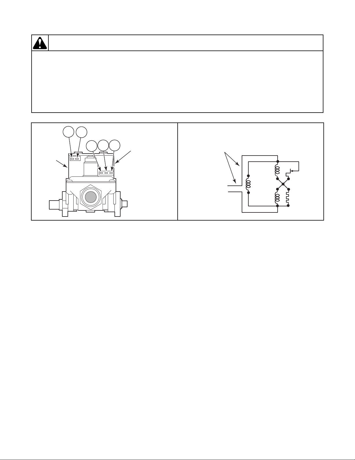
Dryer Test Procedures
To reduce the risk of electric shock, fire, explosion, serious injury or death:
• Disconnect all electric power to the machine and accessories before servicing.
• Close gas shut-off valve to gas dryer before servicing.
• Never start machine with any guards/panels removed.
• Whenever ground wires are removed during servicing, these ground wires must be
reconnected to ensure that the machine is properly grounded.
• Washer motor not grounded! Disconnect electric power before servicing motor.
W502
WARNING
Secondary
Coil
Holding Coil
and
Booster Coil
(Split Coil Valve)
4
1
5
2 3
D267SE3B
Sensor
SECONDARY
COIL
HOLDING
COIL
BOOSTER
COIL
Igniter
120 Volt, 60 Hertz
(208 or 240 Volt/50 Hertz
– refer to machine nameplate)
Electrical Supply Line
D268SE3D
Figure 15
45. Burner System Operation
(Gas Models – Refer to Figure 15.)
a. Components
This burner has four basic components: a
silicon carbide (glow bar) igniter, burner tube,
sensor, and a two-stage gas valve consisting of
a split-coil valve and a secondary coil valve.
The split-coil valve is opened when the dryer
thermostat calls for heat, while the secondary
valve does not open until the igniter has attained
ignition temperature.
b. Pre-Ignition Circuits
When the dryer thermostat calls for heat,
circuits are completed through the holding coil,
sensor, booster coil and igniter. Both coils must
be energized to open the split-coil valve. Once
opened, the holding coil can hold the valve
open without assistance from the booster coil.
The sensor triggers the current to travel around
74 802848
the secondary coil and through the igniter,
causing the igniter to get hot.
c. Burner Circuit
In approximately 30 seconds, the igniter attains
ignition temperature and ignition is made. The
heat from the burner flame causes the sensor
contacts (located on burner housing beside the
© Copyright, Alliance Laundry Systems LLC – DO NOT COPY or TRANSMIT
igniter) to open. A circuit is then completed
through the secondary valve coil, opening the
valve and allowing gas to flow.
d. Momentary Power Interruption
Upon resumption of power, sensor contacts will
still be open, permitting secondary valve to
open. However, with the secondary coil in the
circuit, the booster coil cannot draw enough
current to open the split-coil valve. When
sensor contacts do reclose, the secondary valve
will close, and the burner system will be in the
normal pre-ignition circuit.
e. Flame Failure
In case of flame failure, the sensor contacts will
re-close in about 45 seconds. This will close the
secondary valve and the burner system will be
in the normal pre-ignition circuit.
f. Ignition Failure
If flame is not established as sensor contacts
open, secondary valve will remain open until
sensor contacts re-close. Sensor will continue to
recycle the igniter and secondary valve (about
once per minute) until ignition is made or dryer
is turned off.
Page 77
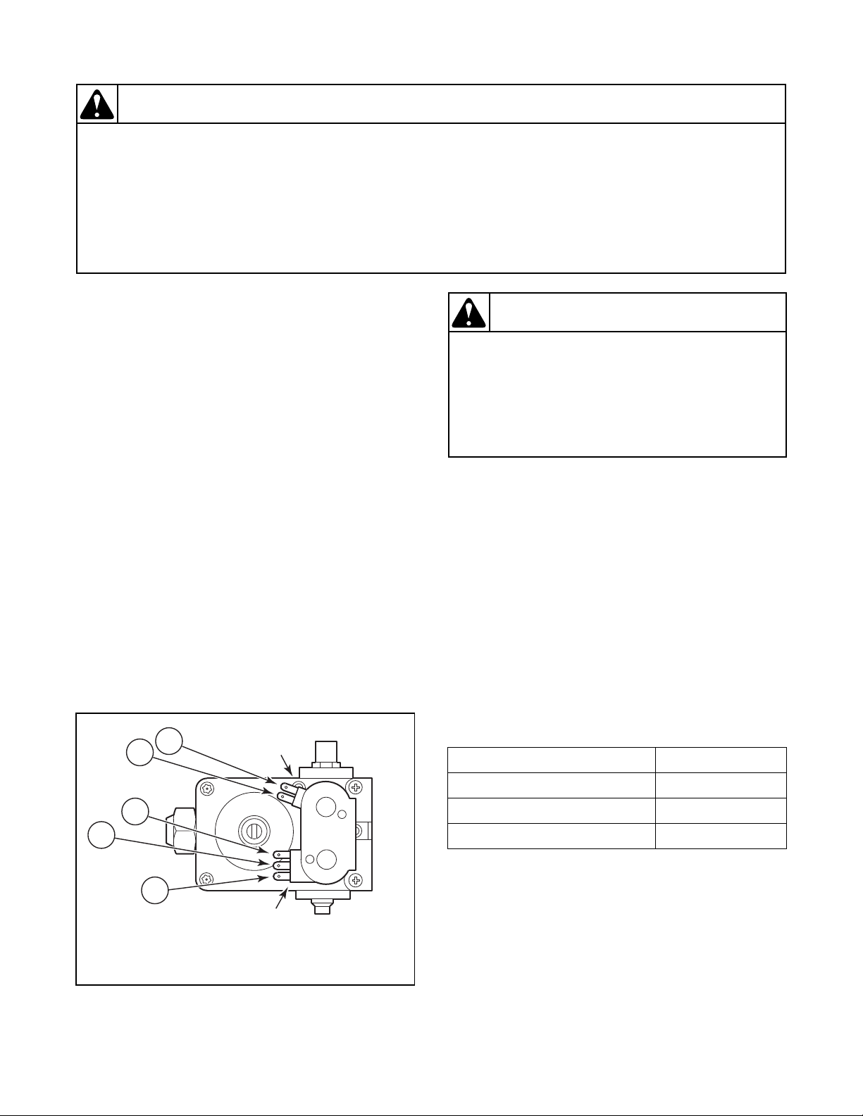
To reduce the risk of electric shock, fire, explosion, serious injury or death:
• Disconnect all electric power to the machine and accessories before servicing.
• Close gas shut-off valve to gas dryer before servicing.
• Never start machine with any guards/panels removed.
• Whenever ground wires are removed during servicing, these ground wires must be
reconnected to ensure that the machine is properly grounded.
• Washer motor not grounded! Disconnect electric power before servicing motor.
W502
WARNING
46. Electrical Circuit To Ignition
1 - 3
4 5
Secondary
Coil
Holding
And Booster
Coil
GAS VALVE FOR SILICON CARBIDE IGNITION
4
5
1
3
2
D270SE3A
To reduce the risk of fire, explosion and
electric shock, close the valve in the gas
supply line to the gas dryer and disconnect
the electrical power unless gas or power
supplies are required to perform test
procedure.
W263
WARNING
System (Gas Models)
a. While supporting the access panel, remove two
screws from bottom edge of access panel.
b. Gently lower the access panel to disengage
locators from bottom edge of front panel.
c. Close main gas shut-off valve. Refer to
Figure 10.
d. Remove valve wire harness disconnect block
from the holding and booster coil. Refer to
Figure 16.
e. Plug dryer power cord into wall receptacle, and
start the dryer in a heat setting (refer to the
Operating Instructions supplied with dryer).
f. Set test meter to read AC voltage and apply
meter probes into terminals on the dryer
harness plug that would correspond to
terminals "1" and "2" on the coil. Refer to
Figure 15. Meter should register line voltage in
all Fabric settings, except FLUFF which should
read “zero” VAC.
g. If meter does not read line voltage in step “f”,
check motor switch, thermostats, fabric switch,
accumulator, or timer.
Dryer Test Procedures
47. Gas Valve Coils Check (Gas Models)
a. While supporting the access panel, remove two
screws from bottom edge of access panel.
b. Gently lower the access panel to disengage
locators from bottom edge of front panel.
c. Close main gas shut-off valve. Refer to
Figure 10.
d. Remove disconnect blocks from gas valve
coils.
e. Set test meter to read Ohms and put meter
probes to terminals shown in Figure 16, and in
the following chart.
COIL TOLERANCE READINGS
Meter probes to terminals: Meter should read:
Holding Coil – Terminals 1 & 2 1365 ± 25 Ohms
Booster Coil – Terminals 1 & 3 560 ± 25 Ohms
Secondary Coil – Terminals 4 & 5 1220 ± 50 Ohms
NOTE: If meter registers any other readings than
those listed above, the respective coil(s) should be
replaced.
802848 75
Figure 16
© Copyright, Alliance Laundry Systems LLC – DO NOT COPY or TRANSMIT
Page 78

Dryer Test Procedures
To reduce the risk of electric shock, fire, explosion, serious injury or death:
• Disconnect all electric power to the machine and accessories before servicing.
• Close gas shut-off valve to gas dryer before servicing.
• Never start machine with any guards/panels removed.
• Whenever ground wires are removed during servicing, these ground wires must be
reconnected to ensure that the machine is properly grounded.
• Washer motor not grounded! Disconnect electric power before servicing motor.
W502
WARNING
SILICON CARBIDE IGNITER AND
BRACKET ASSEMBLY
D337SE3A
Igniter and
Bracket
Attaching
Screw
White
Ceramic
Portion
48. Sensor Check (Gas Models)
a. While supporting the access panel, remove two
screws from bottom edge of access panel.
b. Gently lower the access panel to disengage
locators from bottom edge of front panel.
c. Close main gas shut-off valve. Refer to
Figure 10.
d. Remove wires from sensor terminals.
e. Set test meter to read Ohms and put meter
probes on sensor terminals. Meter should read
“zero” Ohms. If meter registers an Ohm reading
of any amount, replace sensor.
49. Igniter Check (Gas Models)
NOTE: If meter does not read appropriate Ohms,
then replace the igniter.
IMPORTANT: Always examine all wires, terminals
and connectors to be sure wiring is correct before
replacing any components.
a. While supporting the access panel, remove two
screws from bottom edge of access panel.
b. Gently lower the access panel to disengage
locators from bottom edge of front panel.
c. Close main gas shut-off valve. Refer to
Figure 10.
d. Disconnect igniter wires at disconnect block.
e. Set test meter to read Ohms and put meter
probes on terminals of igniter wires.
f. Silicon Carbide Igniter – meter should read
between 45 – 200 Ohms. Refer to Figure 17.
Figure 17
76 802848
© Copyright, Alliance Laundry Systems LLC – DO NOT COPY or TRANSMIT
Page 79

Dryer Test Procedures
To reduce the risk of electric shock, fire, explosion, serious injury or death:
• Disconnect all electric power to the machine and accessories before servicing.
• Close gas shut-off valve to gas dryer before servicing.
• Never start machine with any guards/panels removed.
• Whenever ground wires are removed during servicing, these ground wires must be
reconnected to ensure that the machine is properly grounded.
• Washer motor not grounded! Disconnect electric power before servicing motor.
W502
WARNING
50. Thermal Fuse (Electric Models)
a. While supporting the access panel, remove two
screws from bottom edge of front access panel.
b. Gently lower the access panel to disengage
panel locators from bottom edge of front panel.
c. Label and disconnect wires from thermal fuse.
NOTE: Refer to wiring diagram when rewiring
thermal fuse.
d. Set multimeter to read Ohms. Apply meter
probes to thermal fuse terminals. Multimeter
should read 0 Ohms. If the meter does not show
any reading (infinite Ohms), then the fuse is
open. If the fuse is open, then replace BOTH
the thermal fuse and the limit thermostat.
51. Heater Assembly (Electric Models)
a. While supporting the access panel, remove two
screws from bottom edge of access panel.
b. Gently lower the access panel to disengage
panel locators from bottom edge of front panel.
c. Disconnect wires from heater assembly.
NOTE: Refer to wiring diagram when rewiring
heater assembly.
d. Set meter to read Ohms. Apply meter probes to
the heater assembly terminals. Meter should
read as follows: (Cold Ohms).
Element
Color
Code
Red 5 240 V 60 Hz. 10.39 ± .31 Ohms Cold
White 4.75 208 V 60 Hz. 8.2 ± .5 Ohms Cold
Green 4.8 240 V 50 Hz. 10.75 ± .32 Ohms Cold
Yellow 4 240 V 50 Hz. 13.03 ± .39 Ohms Cold
Blue 3.1 240 V 50 Hz. 16.7 ± .5 Ohms Cold
Orange 5.35 240 V 60 Hz. 9.72 ± .3 Ohms Cold
Purple 4.25 208 V 60 Hz. 9.27 ± .3 Ohms Cold
KW Voltage/Hz. Resistance Reading
52. Cycling or Limit Thermostat
a. While supporting the access panel, remove two
screws from bottom edge of access panel.
b. Gently lower the access panel to disengage
panel locators from bottom edge of front panel.
c. Label and disconnect wires from thermostat.
NOTE: Refer to wiring diagram when rewiring
thermostat.
Cycling Thermostat (S.P.S.T. – 2 Terminals)
or Limit Thermostat
d. Set meter to read Ohms.
(1) Apply meter probes to the thermostat
terminals.
(2) Meter should read “zero.”
802848 77
© Copyright, Alliance Laundry Systems LLC – DO NOT COPY or TRANSMIT
Page 80

Dryer Test Procedures
To reduce the risk of electric shock, fire, explosion, serious injury or death:
• Disconnect all electric power to the machine and accessories before servicing.
• Close gas shut-off valve to gas dryer before servicing.
• Never start machine with any guards/panels removed.
• Whenever ground wires are removed during servicing, these ground wires must be
reconnected to ensure that the machine is properly grounded.
• Washer motor not grounded! Disconnect electric power before servicing motor.
W502
WARNING
53. Door Switch
a. While supporting the access panel, remove two
screws from bottom edge of access panel.
b. Gently lower the access panel to disengage
locators from bottom edge of front panel.
c. Remove two screws holding bottom tabs on
front panel to dryer side panels. Swing bottom
of front panel away from dryer far enough to
disengage hold-down clips and locators from
cabinet top.
d. Disconnect wires from door switch.
NOTE: Refer to model wiring diagram when
rewiring door switch.
e. Set meter to read Ohms and apply meter probes
on switch terminals 1 and 3 with door closed.
You should get “zero” reading.
f. Apply probes to terminals 1 and 2 with door
closed. The meter should read “infinite”.
g. Open door. Meter should read “infinite”
between 1 and 3 and “zero” between 1 and 2.
78 802848
© Copyright, Alliance Laundry Systems LLC – DO NOT COPY or TRANSMIT
Page 81
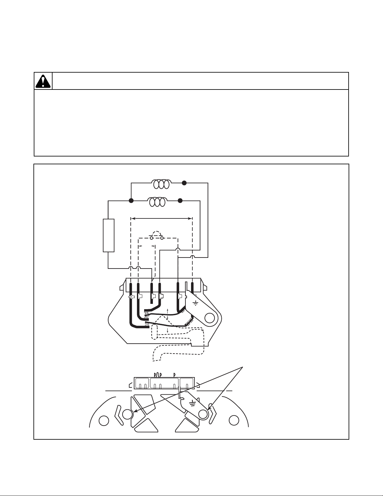
Section 8
To reduce the risk of electric shock, fire, explosion, serious injury or death:
• Disconnect all electric power to the machine and accessories before servicing.
• Close gas shut-off valve to gas dryer before servicing.
• Never start machine with any guards/panels removed.
• Whenever ground wires are removed during servicing, these ground wires must be
reconnected to ensure that the machine is properly grounded.
• Washer motor not grounded! Disconnect electric power before servicing motor.
W502
WARNING
R
R
S
26 4 3 5 1
MAIN
START
ORANGE/COPPER
CUSTOMER CIRCUIT
OVERLOAD
PROTECTOR
BLUE/BROWN
BLACK/COPPER
YELLOW/COPPER
PUSH TO
START
LINE
SWITCH SHOWN IN START POSITION
R.S.P.C.
26 4 3 5 1
G
D329SE3D
G
Motor Switch
Attaching Screws
Internal Wiring of Dryer Motor Switch
Figure 18
802848 79
© Copyright, Alliance Laundry Systems LLC – DO NOT COPY or TRANSMIT
Page 82

Notes
80 802848
© Copyright, Alliance Laundry Systems LLC – DO NOT COPY or TRANSMIT
 Loading...