

Unimac UDGE5BGS113TW01 Installation Manual
Installation Instructions
for Dryers
Original Instructions
Keep These Instructions for Future Reference.
(If this machine changes ownership, this manual must accompany machine.)
www.alliancelaundry.com
Part No. D514816ENR1
May 2017


WARNING
WARNING
Risk of fire. Highly flammable material.
IMPORTANT: Purchaser must consult the local gas
supplier for suggested instructions to be followed if
the dryer user smells gas. The gas utility instructions
plus the SAFETY and WARNING note directly above
must be posted in a prominent location near the dryer
for customer use.
W881
Read all instructions before using unit.
WARNING
FOR YOUR SAFETY, the information in this manual
must be followed to minimize the risk of fire or explosion or to prevent property damage, personal injury or death.
W033
WARNING
• Do not store or use gasoline or other flammable
vapors and liquids in the vicinity of this or any
other appliance.
• WHAT TO DO IF YOU SMELL GAS:
• Do not try to light any appliance.
• Do not touch any electrical switch; do not use
any phone in your building.
• Clear the room, building or area of all occu-
pants.
• Immediately call your gas supplier from a
neighbor’s phone. Follow the gas supplier’s instructions.
• If you cannot reach your gas supplier, call the
fire department.
• Installation and service must be performed by a
qualified installer, service agency or the gas supplier.
WARNING
• Installation of unit must be performed by a qualified installer.
• Install clothes dryer according to manufacturer’s
instructions and local codes.
• DO NOT install a clothes dryer with flexible plastic venting materials. If flexible metal (foil type)
duct is installed, it must be of a specific type
identified by the appliance manufacturer as suitable for use with clothes dryers. Refer to section
on connecting exhaust system. Flexible venting
materials are known to collapse, be easily crushed, and trap lint. These conditions will obstruct
clothes dryer airflow and increase the risk of fire.
W729R1
WARNING
To reduce the risk of severe injury or death, follow all
installation instructions. Save these instructions.
W894
WARNING
FOR YOUR SAFETY
Do not store or use gasoline or other flammable vapors and liquids in the vicinity of this or any other
appliance.
W053
©
Copyright, Alliance Laundry Systems LLC -
DO NOT COPY or TRANSMIT
W052
This product uses FreeRTOS V7.2.0 (www.freertos.org).
3 Part No. D514816ENR1

Table of Contents
Dimensions............................................................................................. 5
Installation............................................................................................. 7
Before You Start............................................................................................. 7
Supplies..................................................................................................... 7
Order of Installation Steps............................................................................7
Position and Level the Dryer............................................................................7
Connect Dryer Exhaust System........................................................................ 9
Exhaust Direction......................................................................................10
Exhaust System.........................................................................................11
Gas Dryers - Connect Gas Supply Pipe........................................................... 11
Reverse Door, if Desired................................................................................13
Wipe Out Inside of Dryer...............................................................................14
Plug In the Dryer.......................................................................................... 15
Electric Dryers with 4-Wire Plug (Supplied with Dryer)................................15
Electric Dryers with 3-Wire Plug (Requires Conversion)...............................16
Gas Dryer................................................................................................. 19
Recheck Steps.............................................................................................. 21
Check Heat Source........................................................................................21
Electric Dryers.......................................................................................... 21
Gas Dryers................................................................................................21
Installer Checklist.................................................................................23
©
Copyright 2017, Alliance Laundry Systems LLC
All rights reserved. No part of the contents of this book may be reproduced or transmitted in any form or by any means without the expressed
written consent of the publisher.
©
Copyright, Alliance Laundry Systems LLC -
DO NOT COPY or TRANSMIT
4 Part No. D514816ENR1
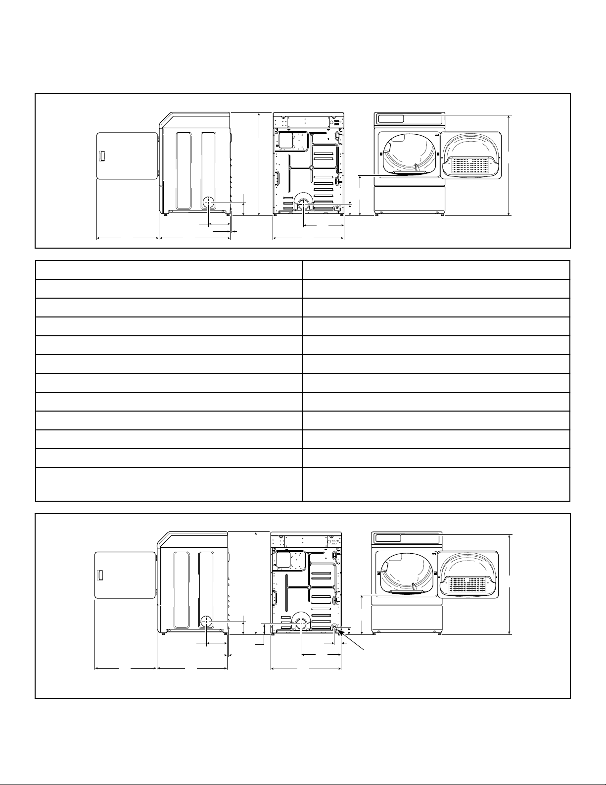
Dimensions
DRY2638N_SVG
JK
I
H
G
F
E
D
C
B
A
DRY2639N_SVG
F
E
D
C
B
A
J
K
M L
I
H
G
1
Electric Models
A * 1027 mm [40.42 in.]
B * 1006 mm [39.61 in.]
C * 392 mm [15.44 in.]
D * 102 mm [4 in.]
Dimensions
E 391 mm [15.4 in.]
F 683 mm [26.875 in.]
G * 114 mm [4.5 in.]
H 10 mm [0.4 in.]
I 203 mm [8 in.]
J 711 mm [28 in.]
K 597 mm [23.5 in.]
NOTE: Exhaust openings are 102 mm [4 inch] metal
* With leveling legs turned into base.
ducting.
Gas Models
1. 3/8 in. NPT Gas Connection
©
Copyright, Alliance Laundry Systems LLC -
DO NOT COPY or TRANSMIT
5 Part No. D514816ENR1
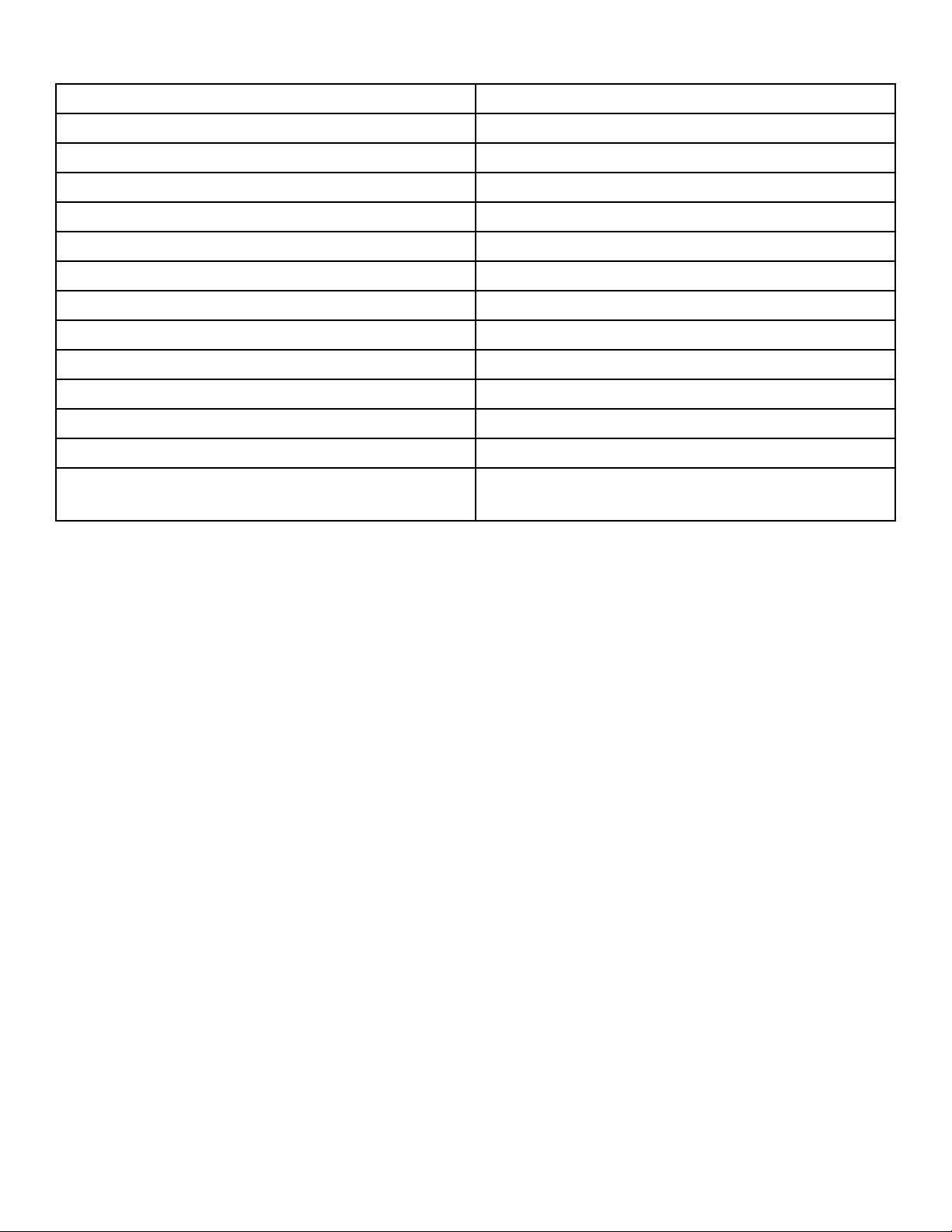
Dimensions
A *1027 mm [40.42 in.]
B *1006 mm [39.61 in.]
C *392 mm [15.44 in.]
D *70 mm [2.8 in.]
E 60 mm [2.3 in.]
F 391 mm [15.4 in.]
G 683 mm [26.875 in.]
H 102 mm [4 in.]
I *114 mm [4.5 in.]
J 10 mm [0.4 in.]
K 203 mm [8 in.]
L 711 mm [28 in.]
M 597 mm [23.5 in.]
NOTE: Exhaust openings are 102 mm [4 inch] metal
ducting.
NOTE: Gas models cannot be vented out left side of
cabinet because of burner housing.
IMPORTANT: The dryer should have sufficient clearance around it for needed ventilation and for the ease
of installation and servicing. For maximum drying performance, we recommend that more clearance be allowed around the dryer than the clearances that are listed throughout this manual.
* With leveling legs turned into base.
©
Copyright, Alliance Laundry Systems LLC -
DO NOT COPY or TRANSMIT
6 Part No. D514816ENR1
Installation
DRY2586N_SVG
8
7
6
5
4
3
2
1
DRY2500N_SVG
3
2
1
Installation
Before You Start
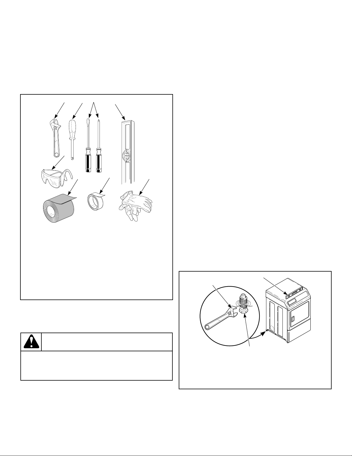
Supplies
For most installations, the basic supplies you will need are:
1. Wrench
2. 1/4 inch Driver
3. Screwdrivers
4. Level
5. Gloves
6. Teflon Tape
7. Duct Tape
8. Safety Glasses
3. For gas models only, connect the gas supply pipe. Check for
gas leaks.
4. Reverse the door, if desired.
5. Wipe out the inside of the dryer.
6. Plug in the dryer.
7. Recheck steps.
8. Start and run the dryer in a heat setting to verify dryer is heating.
Position and Level the Dryer
1. Install dryer before washer. This allows room for attaching
exhaust duct.
2. Select a location with a solid floor. Dryers installed in residential garages must be elevated 457 mm [18 inches] above
the floor.
No other fuel burning appliance should be installed in the same
closet with the dryer.
The dryer must not be installed or stored in an area where it will
be exposed to water and/or weather.
The dryer needs sufficient clearance and an adequate air supply
for proper operation and ventilation, and for easier installation
and servicing. (Minimum clearances are shown in Figure 3 ).
3. Place the dryer in position, and adjust the legs until the dryer
is level from side to side and front to back. Leveling legs can
be adjusted from inside the dryer with a 1/4 in. driver.
4. All four legs must rest firmly on the floor so the weight of the
dryer is evenly distributed. The dryer must not rock.
Figure 1
NOTE: This appliance is suitable for use in countries
having a warm, damp climate.
WARNING
Any disassembly requiring the use of tools must be
performed by a suitably qualified service person.
Order of Installation Steps
1. Position and level the dryer.
2. Connect dryer to exhaust system.
©
Copyright, Alliance Laundry Systems LLC -
DO NOT COPY or TRANSMIT
1. Dryer Base
W299
2. Level
3. Leveling Leg
Figure 2
7 Part No. D514816ENR1
 Loading...