

Page 1
done by Mukade Technical Documentationpage size: A5
Inter-Union Technohandel GmbH
Klaus-von-Klitzing-Str. 2
D-76829 Landau / Pfalz
www.inter-union.de
info@inter-union.de
IAN 59005
IU-Art. Nr: 976331
Model No.: AZ-600
Version: 07/2014
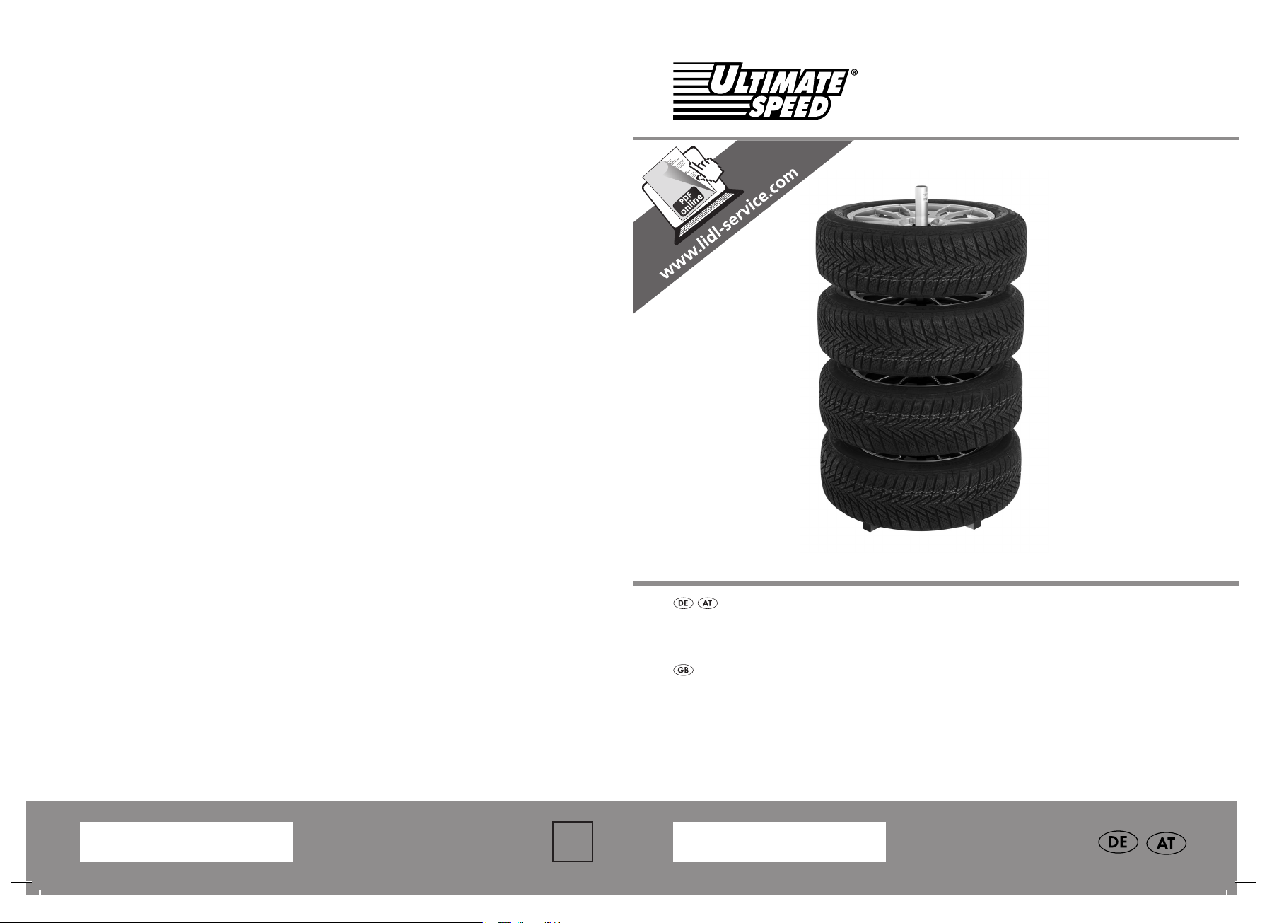
FELGENBAUM
FELGENBAUM
Montage- und Sicherheitshinweise
TYRE HOLDER
Assembly and safety advice
IAN 59005
59005_DE_GB_02.indb 1-2 9/4/14 10:21 am
1
IAN 59005
Page 2

DE/AT Montage- und Sicherheitshinweise Seite 5
GB Assembly and safety advice Page 8
59005_DE_GB_02.indb 3 9/4/14 10:21 am
Page 3
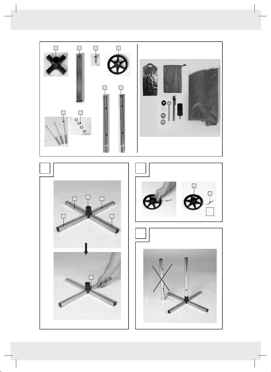
11 x 24 x 34 x
54 x 64 x
44 x
71 x 81 x
A B
1
22
4
5
2 2
C
3
3
59005_DE_GB_02.indb 3 9/4/14 10:21 am
Page 4

E
D
5
7
F
G
8
7
4
59005_DE_GB_02.indb 4 9/4/14 10:21 am
Page 5

FELGENBAUM
Herzlichen Glückwunsch!
Mit Ihrem Kauf haben Sie sich für ein
hochwertiges Produkt entschieden.
§ Einleitung
Machen Sie sich vor der Montage
mit dem Artikel vertraut. Lesen Sie
hierzu aufmerksam die nachfolgende
Montageanleitung und die Sicherheitshinweise.
Benutzen Sie den Artikel nur wie beschrieben und
für die angegebenen Einsatzbereiche. Bewahren
Sie diese Anleitung gut auf. Händigen Sie alle
Unterlagen bei Weitergabe des Artikels an Dritte
ebenfalls mit aus.
§ Bestimmungsgemäße
Verwendung
Der Felgenbaum ist zur Aufbewahrung von
Felgen mit / ohne Reifen bestimmt. Eine
andere Verwendung als zuvor beschrieben
oder eine Veränderung des Produktes ist nicht
zulässig und kann zu Verletzungen und / oder
Beschädigungen des Produktes führen. Für aus
bestimmungswidriger Verwendung entstandene
Schäden übernimmt der Hersteller keine Haftung.
Das Produkt ist nicht für den gewerblichen Einsatz
bestimmt.
§ Teilebeschreibung
1
Plastik-Mittelstück (1x)
2
Ausleger (4x)
3
Schraube (4x)
4
Teller (4x)
5
Stift mit Ringen und Kette (4x)
6
Unterlegscheibe (4x)
7
Mittelrohrstück (ohne Stopfen) (1x)
8
Endrohrstück (mit Stopfen) (1x)
§ TECHNISCHE DATEN
Für Felgen bis 18 Zoll / ca. 46 cm und
max. 225 mm Reifenbreite (225/55 R 18).
§ Zubehör
Entfernen Sie jegliche Verpackungsmaterialien.
Vergewissern Sie sich, dass keine Verpackungsrückstände innerhalb des Felgenbaum verbleiben.
Überprüfen Sie die Lieferung auf Vollständigkeit
und eventuell vorhandene Transportschäden.
Kontaktieren Sie bei beschädigter oder
unvollständiger Lieferung Ihren Händler.
4 Reifenmarkierer zum Aufstecken auf die
Ventile
Profiltiefenmesser
Druckluftprüfer
Schutzhülle
Schraubenschlüssel
Aufbewahrungstasche
Schraubenbeutel
SICHERHEITSHINWEISE
Kinder und Personen, die aufgrund ihrer
Beachten Sie alle Sicherheitshinweise,
Bewahren Sie die Aufbauanleitung für den
Bevor Sie den Artikel benutzen,
lesen Sie sich diese
Aufbauanleitung sorgfältig durch.
Sie enthält wichtige Informationen für Ihre
Sicherheit sowie zum Gebrauch und zur
Pflege des Artikels.
physischen, sensorischen oder geistigen
Fähigkeiten oder ihrer Unerfahrenheit oder
Unkenntnis nicht in der Lage sind, den Artikel
sicher zu bedienen, dürfen den Artikel
nicht benutzen, es sei denn, sie werden
durch eine für ihre Sicherheit zuständige
Person beaufsichtigt oder erhielten von ihr
Anweisungen, wie der Artikel zu benutzen ist.
um Schäden durch nicht sachgemäßen
Gebrauch zu vermeiden! Beachten Sie alle
Warnhinweise auf dem Artikel.
weiteren Gebrauch auf. Sollte dieser Artikel
an Dritte weitergegeben werden, muss diese
Aufbauanleitung mit ausgehändigt werden.
Maximale Last je Auflageteller: 25 kg
Maximale Gesamtlast: 100 kg
DE/AT
5
59005_DE_GB_02.indb 5 9/4/14 10:21 am
Page 6

Es wird keine Haftung für Schäden und
Folgen durch unsachgemäße Behandlung,
Nichtbeachtung der Sicherheitshinweise,
Montagefehler oder jedwede Änderung an
dem Artikel übernommen.
Bitte verwenden Sie nur Originalteile aus
dem Lieferumfang. Für Ersatzteilfragen
wenden Sie sich bitte an unten stehende
Adresse.
Bitte wählen sie vor dem Auflegen der
Räder den endgültigen Standort für Ihren
Felgenbaum aus. Ein nachträglicher Transport
ist wegen des hohen Gewichts und der
Kippgefahr zu vermeiden!
Felgenbaum nur auf ebenem und festem
Grund aufstellen. Die Aufstellfläche darf nicht
geneigt sein, da die Standsicherheit sonst
nicht gegeben ist.
Der Felgenbaum ist regelmäßig auf Schäden
oder Verschleiß zu prüfen und bei Defekt
nicht weiter zu benutzen.
Der Felgenbaum darf nicht für andere
Zwecke (z.B. als Leiter oder Unterstellbock)
verwendet werden.
Den Felgenbaum ( Montage) wegen
Kippgefahr nur von unten nach oben
beladen, um Verletzungen zu vermeiden.
Kinder vom Felgenbaum fernhalten.
Belasten Sie den Felgenbaum nicht über der
max. zulässigen Last ( Technische Daten).
Mittelrohrstück 7 (Abb. C) in die Öffnung
des Kunststoff Mittelstückes 1 einsetzen,
Teller 4 über das Mittelrohrstück streifen.
Stift 5 durch die unterste Bohrung stecken
und Teller 4 auflegen (Abb. D).
Felge mit Reifen auflegen. Teller 4 über das
Mittelrohrstück 7 streifen. Stift 5 durch die
nächste freie Öffnung stecken und Teller 4
auflegen (Abb. E).
Felge mit Reifen auflegen (Abb. E).
Nun das Endrohrstück 8 aufsetzen, bis die
Kugel des Endrohrstückes 8 in der Öffnung
des Mittelrohrstückes 7 eingerastet ist
(Abb. F). Verfahren Sie wie zuvor
beschrieben, bis alle 4 Räder ordentlich
aufgelegt sind (Abb. G).
Ziehen Sie die Schutzhülle komplett über den
Felgenständer.
§ HINWEIS ZUR VERWENDUNG
DER REIFENMARKIERER
Auf den Reifenmarkierern ablesen, für
welchen Reifen der jeweilige Reifenmarkierer
vorgesehen ist. Stecken Sie den entsprechenden
Reifenmarkierer auf das Ventil des
entsprechenden Reifens.
§ HINWEIS ZUR VERWENDUNG
DES PROFILTIEFENMESSERS
§ MONTAGE
Zuerst Plastik-Mittelstück 1 und Ausleger
2
des Fußes zusammenstecken (Abb. A)
(ggf. mit Gummihammer etwas nachhelfen)
und mit beigefügten Schrauben 3 mit
beiliegendem Schraubenschlüssel (aus
Aufbewahrungstasche) fixieren (Abb. A).
An jedem Teller 4 1 Stift mit Kette und
Ringen 5 fixieren (Abb. B).
DE/AT
6
59005_DE_GB_02.indb 6 9/4/14 10:21 am
Bitte informieren Sie sich vor Verwendung
des Profiltiefenmessers über die gesetzlichen
Bestimmungen zur Reifenprofiltiefe.
Page 7

§ ANLEITUNG
DRUCKLUFTPRÜFER
Entfernen Sie die Ventilkappe des Reifens.
Setzen Sie den Druckluftprüfer auf das Ventil
des Reifens.
Lesen Sie an der Skala des Druckluftprüfers
den Luftdruck Ihres Reifens ab.
Vergleichen Sie den vorhanden Luftdruck
mit dem in der Bedienungsanleitung Ihres
Fahrzeuges aufgeführten Luftdruck, um
sicherzugehen, dass der Reifendruck korrekt
ist. Pumpen Sie gegebenenfalls Luft auf oder
lassen Luft ab.
Hinweis: Die Kontrolle des Luftdrucks der
Reifen sollte weiterhin in den vorgegebenen
Intervallen mit einem geeigneten
Messinstrument durchgeführt werden.
§ WARTUNG UND PFLEGE
§ Garantie
3 Jahre Garantie ab Kaufdatum auf dieses
Gerat, gilt nur gegenüber dem Ersteinkäufer,
nicht übertrag bar. Bitte Kassenbon als
Nachweis aufbewahren. Die Garantie gilt nur
für Material- oder Fabrikationsfehler, nicht aber
für Verschleißteile oder für Beschädigungen
durch unsachgemäßen Gebrauch. Die Garantie
erlischt bei Fremdeingriff. Ihre gesetzlichen Rechte
werden durch diese Garantie nicht eingeschränkt.
Im Garantiefall mit der Servicestelle in
Verbindung setzen. Nur so kann eine kostenlose
Einsendung Ihres Gerätes gewährleistet werden.
Service / Hersteller:
Inter-Union Technohandel GmbH
Klaus-von-Klitzing-Str. 2
D–76829 Landau/Pfalz
Den Felgenbaum regelmäßig auf Schäden oder
Verschleiß prüfen und bei Defekt nicht weiter
benutzen.
Zur Reinigung einen feuchten, weichen Lappen
ohne Zusatz von Reinigungs- oder Lösemittel
verwenden.
§ Entsorgung
Die Verpackung besteht aus umweltfreundlichen
Materialien. Entsorgen Sie diese in den örtlichen
Recyclingbehältern.
Möglichkeiten zur Entsorgung des ausgedienten
Produkts erfahren Sie bei Ihrer Gemeinde- oder
Stadtverwaltung.
www.inter-union.de
info@inter-union.de
Tel.: 06341 284332
(Standard Festnetzpreis in Deutschland)
IAN 59005
IU-Art.-Nr.: 976331
Modell-Nr.: AZ-600
Seriennummer: 07/2014
DE/AT
7
59005_DE_GB_02.indb 7 9/4/14 10:21 am
Page 8

TYRE HOLDER
§ ACCESSORIES
Congratulations!
With your purchase you have chosen a product
of very high quality.
§ INTRODUCTION
Get familiar with this product before
assembling. Read the following
assembly instructions and safety
precautions carefully. Use the product only
as described and only for the intended use
as mentioned. Keep this manual for future
reference. When passing on this product to third
parties make sure to also hand over all relevant
documentation.
§ INTENDED USE
The tyre holder is intended for storing tyre with /
without wheels. Any use other than mentioned
before or modifications to the product are not
permitted and can cause injuries and / or
damage to the product. The manufacturer is not
liable for any damage resulting from unintended
use. The product is not intended for commercial
use.
§ PART DESCRIPTION
1
Plastic centrepiece (1x)
2
Crossbeam (4x)
3
Screw (4x)
4
Disc (4x)
5
Pin with rings and chain (4x)
6
Washer (4x)
7
Center length of pipe (without stopper) (1x)
8
End length of pipe (with stopper) (1x)
§ TECHNICAL DATA
For 18 inch / approx. 46 cm wheel rims and tire
section width of max. 225 mm (225/55 R 18).
Remove all packaging materials.
Make sure there is no packaging residue left
within the tyre holder. Check the delivery content
for completeness and any potential transport
damage. In case the product is incomplete or
damaged, contact your dealer.
4 wheel markers for attachment to the valves
Tire tread depth gauge
Air pressure tester
Protective cover
Screwdriver
Storage pouch
Hardware bag
SAFETY INFORMATION
Persons or children who are not capable of
Observe all safety precautions in order to
Keep the assembly instructions for future
Carefully read these assembly
instructions before using the
product. The instructions contain
important information related to your safety
and to the use and maintenance of the
product.
using this product safely due to their limited
physical, sensory or mental capabilities, or
lack of knowledge or experience, must not
use this product unless they have been given
supervision or instructions on the safe use of
the product by a person responsible for their
safety.
avoid damage from improper use! Observe
all warnings on the product.
reference. When passing on this product to
third parties make sure to also hand on these
assembly instructions.
Maximum load per each disc: 25 kg
Maximum total load: 100 kg
GB
8
59005_DE_GB_02.indb 8 9/4/14 10:21 am
Page 9

We are not liable for any damage and
consequences resulting from improper use,
non-observance of safety precautions,
assembly mistakes or any modifications to the
product.
Only use original parts included in the
delivery scope. Contact the address
below if you have any requests regarding
replacement parts.
Select the final location for your tyre holder
before attaching any tyre. Moving the
product later on should be avoided due to its
heavy weight and risk of overturning!
Install the tyre holder on a flat and stable
surface only. The installation surface must not
be tilted, as a stable stand can otherwise not
be guaranteed.
Check the tyre holder regularly for damage
and wear and stop using it in case of any
defects.
Do not use the tyre holder for any other
purposes (e.g. as ladder or safety stand).
Due to its risk of overturning the tyre holder
( Assembly) must only be loaded from
down to up in order to avoid injuries.
Keep children away from the tyre holder.
Do not load the tyre holder beyond the
maximum permissible load ( Technical
Data).
Insert the center length of pipe 7 (fig. C) into
the opening of the plastic centrepiece 1 ;
slide the disc 4 over the center length of
pipe. Insert the pin 5 through the lowest
borehole and attach the disc 4 (fig. D).
Attach the rim with wheel. Slide the disc 4
over the center length of pipe 7 ; insert the
pin 5 through the next available bore hole
and then attach the disc 4 (fig. E).
Attach the rim with wheel (fig. E).
Then attach the end length of pipe 8 until
the ball of the end length of pipe 8 locks
into the opening of the center length of pipe
7
(fig. F). Continue as described previously
until all 4 wheels are attached properly
(fig. G).
Cover the entire tyre holder with the
protective cover.
§ TIPS FOR USING THE WHEEL
MARKERS
Read the wheel markers’ indication to find out
for which wheel each of them is intended. Attach
the respective wheel marker to the valve of the
corresponding wheel.
§ TIPS FOR USING THE TIRE
TREAD DEPTH GAUGE
§ INSTALLATION
First attach the plastic centrepiece 1 to
Before using the tire tread depth gauge, inquire
the legal regulations regarding tire tread depths.
the crossbeam 2 of the stand (fig. A) (if
necessary use a rubber mallet to facilitate
attachment) and secure it with the screws
2
and screwdriver provided (see storage
pouch) (fig. A).
Attach 1 pin with rings and chain 5 each to
each of the discs 4 (fig. B).
GB
9
59005_DE_GB_02.indb 9 9/4/14 10:21 am
Page 10

§ INSTRUCTION FOR USING THE
AIR PRESSURE TESTER
Remove the valve cap from the wheel.
Attach the air compression tester to the valve
of the wheel.
Check the scale of the air pressure tester for
the air pressure reading of the wheel.
Compare the current air pressure reading
with the air pressure stated in the operating
manual of your car to make sure the tire
pressure is correct. If necessary, add or
release some air.
Note: Continue to check the air pressure of
the tires at predetermined intervals using a
suitable measuring device.
§ CLEANING AND CARE
Regularly check the tyre holder for damage or
wear and stop using it in case of any defects.
Clean with a damp, soft cloth without any
cleaning agents or solvents.
§ DISPOSAL
The packaging is made of environmentally
friendly material. Dispose of at local recycling
facilities.
Contact your local authority or municipality to
get more information on the disposal of waste
equipment.
§ WARRANTY
This product comes with a warranty of 3 years
starting on the date of purchase. It extends only
to the original end user and is not transferable.
Keep the purchase receipt as prove. The warranty
covers material or manufacturing defects but does
not extend to parts subject to wear or to damage
resulting from improper use. Unauthorized
interferences will void the warranty. Your statutory
rights are not affected by this warranty.
Contact our service department for any warranty
claims. Only then can we guarantee the return of
your product free of charge.
SERVICE / MANUFACTURER:
Inter-Union Technohandel GmbH
Klaus-von-Klitzing-Str. 2
D–76829 Landau/Pfalz
www.inter-union.de
info@inter-union.de
Tel.: 06341 284332
(Standard landline rates in Germany)
IAN 59005
IU Art. No.: 976331
Model No.: AZ-600
Serial number: 07/2014
GB
10
59005_DE_GB_02.indb 10 9/4/14 10:21 am
 Loading...