


Enterprise WiFi System
Model: UAP-Outdoor+
Introduction
Thank you for purchasing the Ubiquiti Networks™ UniFi™ Enterprise WiFi System. The UniFi Enterprise WiFi System includes the UniFi Controller software, which allows you to manage your wireless network using a web browser.
The UniFi Controller software and User Guide are available for download at downloads.ubnt.com/unifi
This Quick Start Guide includes the warranty terms and is for use with the UniFi AP Oudoor+, model UAP-Outdoor+. The UniFi AP can be powered by any of the following:
•PoE Adapter (included)
•48V, PoE 802.3af compliant switch
•Ubiquiti Networks TOUGHSwitch PRO, model TS-8-PRO
The UniFi AP also includes the necessary hardware for mounting the unit on a wall or a pole.
Installation Requirements
•Flathead screwdriver (for pole-mounting)
•Drill and 6 mm drill bit (for wall-mounting)
•Phillips screwdriver
•Shielded Category 5 (or above) cabling should be used for all outdoor wired Ethernet connections and should be grounded through the AC ground of the PoE.
We recommend that you protect your networks from brutal outdoor environments and devastating ESD attacks with industrial grade shielded Ethernet cable from
Ubiquiti Networks. For more details, visit www.ubnt.com/toughcable
TERMS OF USE: Ubiquiti radio devices must be professionally installed. Shielded Ethernet cable and earth grounding must be used as conditions of product warranty. TOUGHCable is designed for outdoor installations. It is the customer’s responsibility to follow local country regulations, including operation within legal frequency channels, output power, and Dynamic Frequency Selection (DFS) requirements.

Package Contents
|
|
|
|
|
|
|
|
|
UniFi AP Outdoor+ |
Antennas (Qty. 2) |
Wall Mount Bracket |
||||||
Metal Strap |
Screws |
Screw Anchors |
|
(M2.9x20, Qty. 3) |
(M3x20, Qty. 3) |
PoE Adapter |
Power Cord |
Quick Start |
(48V, 0.5A) |
|
Guide |
System Requirements
•Microsoft Windows Vista, Windows 7, Windows 8, or
Mac OS X
•Java Runtime Environment 1.6 (or above)
•Web Browser: Mozilla Firefox, Google Chrome, or Microsoft Internet Explorer 8 (or above)

Network Topology Requirements
•A DHCP-enabled network for the AP to obtain an IP address (wireless clients will also obtain IP addresses after deployment)
•A management station computer running the UniFi Controller software, located either onsite and connected to the same Layer 2 network, or off-site in a cloud or NOC
UAP-Outdoor+ |
UAP-AC |
|
Router |
UAP-PRO |
UAP |
|
or |
On-Site |
O -Site |
Management Station |
Cloud/NOC |
Sample Network Diagram
All UniFi APs support off-site management controllers. For setup details, refer to the User Guide on the website: documentation.ubnt.com/unifi

Hardware Overview
LED
|
|
|
|
|
|
|
|
|
|
LED Color |
Status |
|||
Flashing White |
Initializing. |
|||
|
|
|||
Steady White |
Factory default, waiting to be integrated. |
|||
|
|
|
||
Alternating |
Device is busy; do not touch or unplug it. |
|||
This usually indicates that a process such |
||||
White/Blue |
||||
as a firmware upgrade is taking place. |
||||
|
|
|||
|
|
This is used to locate an AP. |
||
Quickly |
When you click Locate in the UniFi |
|||
Controller software, the AP will flash. It |
||||
Flashing Blue |
||||
will also display the location of the AP on |
||||
|
|
|||
|
|
the map. |
||
|
|
Indicates the device has been successfully |
||
Steady Blue |
integrated into a network and is working |
|||
|
|
properly. |
||
|
|
|||
Steady Blue |
Indicates the device is in an isolated state |
|||
with occasional |
(all WLANs are brought down until an |
|||
flashing |
uplink is found). |
|||
|
|
|
|
|
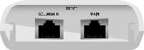
Ports
|
|
|
|
|
|
|
|
|
|
|
|
|
|
|
|
|
|
|
|
|
|
|
|
|
|
|
|
|
|
|
|
|
|
|
|
|
|
|
|
|
|
|
|
|
|
|
|
Secondary |
|
|
Reset |
|
|
Main |
|||||
|
|
|
|||||||||
Ethernet Port |
Button |
|
Ethernet Port |
||||||||
(10/100 Mbps) |
|
|
|
|
|
(10/100 Mbps) |
|||||
Secondary The Secondary Ethernet port is used for bridging.
Reset The Reset button serves two functions for the UniFi AP:
•Restart Press and release the Reset button quickly.
•Restore to Factory Default Settings Press and hold the
Reset button for more then five seconds.
Main The Main Ethernet port is used to connect the power and should be connected to the LAN and DHCP server. Power can be provided by any of the following:
•Included PoE adapter
•48V, 802.3af compliant switch
•Ubiquiti Networks TOUGHSwitch PRO, model TS-8-PRO
*720-00028-01*
720-00028-01

Hardware Installation
The UniFi AP can be mounted to a wall or on a pole. Perform the steps for the appropriate installation:
Wall Mount
To mount the AP on a wall, use the included Wall Mount Bracket, Screws, and Screw Anchors.
1.Place the Wall Mount Bracket at the desired location on the wall, with the one screw hole pointed towards the ground.
2.Use a pencil to mark the three holes on the wall.
3.Use a 6 mm drill bit to drill the holes in the wall.
4.Insert a Screw Anchor into each hole.
5.Secure the Wall Mount Bracket to the wall with the self tapping Screws.

6.Align the mounting tabs on the UniFi AP with the notches on the Wall Mount Bracket, and slide the UniFi AP down until it locks into place.
 Loading...