


GPON CPE
Model: UF-LOCO

Introduction
Thank you for purchasing the Ubiquiti Networks® U Fiber loco. This Quick Start Guide is designed to guide you through the installation and also includes the warranty terms.
Package Contents
UFiber loco |
Wall Mount Bracket |
Screws |
|
|
(Qty. 4) |
|
|
|
|
|
|
Screw Anchors |
Micro-USB Power Adapter* |
Quick Start |
(Qty. 4) |
(5V, 1A) |
Guide |
* Included only in the single-pack of the UF-LOCO.
System Requirements
•Linux, Mac OS X, or Microsoft Windows 7/8/10
•Web Browser: Google Chrome (Other browsers may have limited functionality)
TERMS OF USE: All Ethernet cabling runs must use CAT5 (or above). It is the professional installer’s responsibility to follow local country regulations, including operation within legal frequency channels, output power, and indoor cabling requirements.
Hardware Overview
Reset Button
The Reset button serves two functions for the UF-LOCO:
•Restart Press and release the Reset button quickly. The three signal LEDs will flash amber.
•Restore to Factory Default Settings Press and hold the
Reset button for more than five seconds. The three signal
LEDs will light amber in this sequence with a 100-ms delay between patterns:
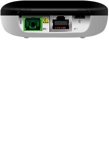
Ports
Port |
Description |
|
|
PON |
SC/APC GPON port supports WAN connections of |
|
2.488 Gbps downstream and 1.244 Gbps upstream. |
|
The Micro-USB Power Adapter connects to this port. |
|
|
|
The RJ45 Ethernet port supports a |
|
10/100/1000 Mbps connection and passive 24V |
|
PoE to power the device. |

LEDs
Ethernet
Signal
Power
Ethernet LED
LED State |
Status |
Off |
Ethernet connection down |
White |
Ethernet connection up |
Power LED
LED State |
Status |
|
Off |
Power off |
|
|
|
|
White |
Power on |
|
|
|

Signal LEDs
LED |
State |
Status |
|
|
|
|
Off |
Bootup |
|
|
|
|
(1) White |
Signal strength: low |
|
≥ -28 dBm |
|
|
|
|
|
(2) White |
Signal strength: good |
|
≥ -25 dBm |
|
|
|
|
|
(3) White |
Signal strength: strong |
|
≥ -11 dBm |
|
|
|
|
|
|
|
|
|
Signal strength: too low |
|
|
< -28 dBm |
|
(1) Amber |
Check the quality of the fiber |
|
|
|
|
|
connection, and calculate the total |
|
|
optical loss of the optical splitters. |
|
|
Signal strength: too strong |
|
(1) Amber |
≥ -8 dBm |
|
(2) White |
Add an optical splitter, or add |
|
|
|
|
|
a 5 or 10 dB optical attenuator. |
|
|
No signal |
|
(3) Amber |
Check the fiber cables and |
|
connectors, and ensure that the OLT |
|
|
|
|
|
|
functions properly. |
|
Alternating |
No authority |
|
Between |
The UF-LOCO has not been |
|
(2) Amber |
|
|
authorized or cannot communicate |
|
|
(1) White |
|
|
with the OLT. Check passwords and |
|
|
|
|
|
and |
OLT settings. |
|
|
|
(Varies) |
Signal |
|
Strength |
|
|
|
|

Hardware Installation
The UF-LOCO can be mounted on a wall or placed on a desktop.
WARNING: To reduce the risk of fire or electric shock, do not expose the UF-LOCO to rain or moisture.
Wall Mounting
1.Use the Wall Mount Bracket as a template and drill four
6 mm holes as shown below.
40 mm
40mm
2.Insert a Screw Anchor into each hole, and then fasten the
Wall Mount Bracket using four Screws.
*640-00355-03*
640-00355-03
3.Mount the UF-LOCO by inserting the top of the UF-LOCO into the Mount Bracket and then pivot the bottom into the bracket until it locks into place.

Connecting Fiber
Connect the fiber optic cable from the Passive Optical Network to the PON port.
 Loading...