


Model: UCK-G2-PLUS

Introduction
Thank you for purchasing the Ubiquiti Networks® UniFi® Cloud Key Gen2 Plus. This Quick Start Guide is designed to guide you through installation and also includes warranty terms.
Package Contents
UniFi Cloud Key Gen2 Plus
System Requirement
Web Browser: Google Chrome (Other browsers may have limited functionality.)
TERMS OF USE: All Ethernet cabling runs must use CAT5 (or above). It is the professional installer’s responsibility to follow local country regulations, including operation within legal frequency channels, output power, indoor cabling requirements, and Dynamic Frequency Selection (DFS) requirements.

Network Topology
A DHCP-enabled network (for the Cloud Key Gen 2 Plus to obtain an IP address)
UniFi Cloud Key Gen2 Plus
UniFi PoE Switch
LAN
|
|
|
|
|
|
|
|
|
|
|
|
|
|
|
|
UniFi Security Gateway |
WAN |
|
|
|
|
|
|
|
|
||||||
(DHCP Server) |
|
|
|
|
|
|
|
|
|
|
|
|
|||
Internet
Sample Network Diagram

Hardware Overview
Front Panel LED
|
|
|
|
LED |
|
|
|
|
|
|
|
|
||
Color |
State |
Status |
||
White |
Solid |
Device is ready to be configured |
||
|
|
|
||
|
Flashing |
Device is booting up |
||
|
|
Device is initializing/deinitializing |
||
|
Heartbeat |
Firmware update in process |
||
Blue |
Solid |
Device is configured and ready |
||
|
Flashing |
Main power has been lost and |
||
|
|
device is counting down. |
||
|
|
If power is restored within 10 |
||
|
|
seconds, the device will return to |
||
|
|
its previous state. If power is not |
||
|
|
restored within 10 seconds, the |
||
|
|
device will safely shutdown. |
||
|
Slow |
Client connected to device via |
||
|
Flashing |
Bluetooth (BLE) |
||
Off/White/ |
Flashing |
Device is in recovery mode. |
||
Blue |
|
|
|
|
|
|
|
|
|

Front Panel
HDD |
|
|
|
|
LCD |
||
Bay |
|
|
|
|
|
|
Screen |
|
|
|
|
|
|
|
|
HDD Bay Location of the 2.5" SATA hard disk drive
LCD Screen Displays device status information and will vary based on the application currently in use
LCD Display for UniFi SDN
Icon Description
UniFi SDN Controller name and connection speed
Number of client devices on the network
Number of managed UniFi SDN devices
Status of Cloud Access

LCD Display for UniFi Protect
Icon Description
UniFi Protect Controller name and connection speed
Status of Cloud Access
Number of active cameras registered in UniFi Protect
Time of last motion detected by UniFi Protect
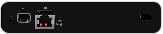
Back Panel
|
|
Reset |
|
microSD |
USB Type C |
|||||||
|
Button |
|
|
Slot |
Port |
|||||||
Power |
|
|
|
|
|
|
|
|
|
|||
|
|
|
|
|
|
|
|
|
||||
Button |
|
|
|
|
|
|
|
|||||
|
|
|
|
|
|
|
|
|
|
|
|
|
USB Type C |
|
|
|
|
Ethernet |
|
|
|||||
Power Port |
|
|
|
Port |
|
|
||||||
Reset The Reset button serves two functions:
•Restart Press and release the Reset button quickly.
•Restore to Factory Default Settings Press and hold the
Reset button for more than five seconds, until the status LED begins flashing white.
Power Button Press to turn the Cloud Key Gen 2 Plus on or off.
USB Type C Power Port Used for power if PoE is not available. Quick Charge 2.0 or Quick Charge 3.0 compliance is required.
microSD Slot Used for external backup (microSD card not included).
Ethernet Port Connects to a gigabit switch port on your LAN. Power can be provided by an 802.3af PoE switch, such as the
UniFi PoE Switch.
USB Type C Port Reserved for future use.

Side Panels
Security
Slot
Rack-Mount |
|
|
|
Rack-Mount |
Notch |
|
|
|
Notch |
Security Slot Allows the Cloud Key Gen 2 Plus to be used with a Kensington security lock (not included). When used, it also prevents removal of the HDD while the device is in use.
Rack-Mount Notch Locks the Cloud Key Gen2 Plus in place.

Bottom Panel
|
|
|
|
|
|
|
|
|
|
|
|
|
|
|
|
|
|
13-Pin Connector |
HDD Latch |
||||
13-Pin Connector Connects the Cloud Key Gen2 Plus to the optional Rackmount Accessory (not included).
Note: Only remove the pre-installed sticker that covers the 13-Pin Connector when using the Cloud Key Gen2
Plus with the optional Rackmount Accessory.
HDD Latch Releases the HDD tray from the drive bay.
WARNING: Do not operate the HDD Latch while the Cloud Key Gen2 Plus is powered on.

Hardware Installation
1.Connect an Ethernet cable (not included) to the
Ethernet Port.
2.Connect the other end of the Ethernet cable to a port on a network switch, such as a UniFi PoE Switch.
1 |
|
|
|
|
3 |
|
|
|
|
|
5 |
|
|
|
|
7 |
|
|
|
2 |
9 |
|
|
|
4 |
11 |
|
|
|
|
6 |
13 |
|
|
|
8 |
15 |
|
|
|
10 |
|
17 |
|
|
12 |
|
19 |
|
|
|
14 |
21 |
|
|
|
16 |
|
22 |
|
|
|
18 |
|
|
|
|
20 |
SFP1 |
|
|
|
22 |
|
|
|
|
|
24 |
|
|
|
|
SFP2 |
Powering the Cloud Key Gen2 Plus
Use an 802.3af-compliant switch, such as a UniFi PoE Switch, a USB power source, or 48V PoE adapter (not included).
UniFi Switch
The Cloud Key Gen 2 Plus can be powered by a UniFi PoE
Switch or other 802.3af-compliant switch.
|
15 |
|
|
|
17 |
|
|
19 |
|
|
21 |
|
16 |
22 |
|
|
18 |
1 |
|
20 |
3 |
|
22 |
5 |
|
24 |
|
7 |
|
2 |
9 |
|
4 |
11 |
|
6 |
13 |
|
|
8 |
|
|
10 |
|
|
12 |
|
|
14 |
|
SFP1
SFP2
UniFi Switch Power Connection Diagram
USB Power Source
Connect a USB cable (not included) from the Cloud Key Gen 2
Plus directly to a USB power source: Quick Charge 2.0 or
Quick Charge 3.0 compliance is required.
USB Power Connection Diagram

Optional Rackmount Accessory
There is an optional UniFi Rackmount Accessory (sold separately) that can mount the Cloud Key Gen2 Plus in a standard 19" rack.
Lock Tab
Docking
Bay
To install the Rackmount Accessory, follow these instructions:
1.Attach the UniFi Rackmount Accessory to the rack using four Mounting Screws. (If the rack has square slots, then use
Cage Nuts with the Mounting Screws.)
2.Connect an Ethernet cable (not included) to the Ethernet Port on the front of the Rackmount Accessory.
3.Connect the other end of the Ethernet cable to a port on a compatible PoE switch, such as a UniFi PoE Switch.
 Loading...