

Page 1
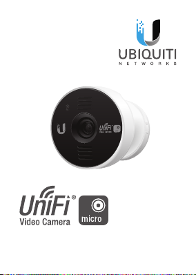
Model: UVC-Micro
Quick Start Guide
®
Page 2
Before You Begin
The UVC Micro is designed to work
with the UniFi® Video (v3.1.1 or higher)
controller software. The software may
be hosted on either:
• The Ubiquiti Networks®
UniFiNVR appliance (UVC‑NVR)
• A Linux/Windows computer
Note: The latest UniFi Video
software is available for free
download at:
downloads.ubnt.com/unifivideo
Page 3
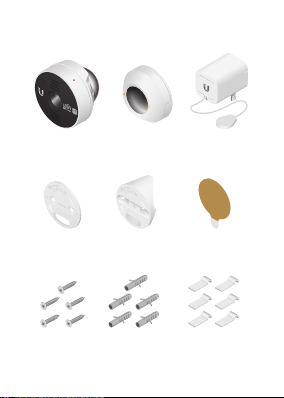
Package Contents
UVC-Micro
Camera
Flat Base
Plate
Screws
(Qty. 5)
UVC-Micro
Base
Corner Base
Plate
Screw
Anchors
(Qty. 5)
Power
Adapter
Mounting
Tape
Cable Clips
(Qty. 6)
Page 4
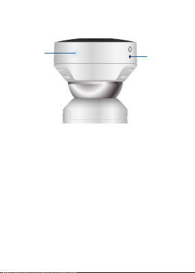
Hardware Overview
LED
LED The LED will light steady blue
during bootup. When the camera is
ready to connect to the Wi-Fi network,
the LED pattern will flash two times
accompanied by two beep tones. Once
connected to the network, the LED will
glow a breathing pattern.
Reset To reset network settings to
factory defaults, press and hold the
Reset button until the camera beeps two
fast tones.
Reset
Page 5

Installation
Extend the Power Cable
The Power Adapter has an extendable
power cable that is concealed inside the
adapter casing.
1. Hold the outer casing of the Power
Adapter with the Ubiquiti U logo
facing towards you, and push in the
center of the logo until the adapter
releases from the outer casing.
Page 6
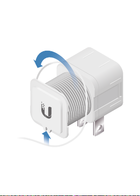
2. Unwind the power cable to extend it
to the desired length. Then lock the
cable into the notch located under
the bottom of the U logo.
3. Slide the outer casing back onto the
adapter until it snaps into place.
Page 7
Mounting Options
The camera may be used free-standing
or mounted in several ways:
• Magnetic Mounting
• Mounting with Tape
• Wall Mounting with Screws
• Corner Mounting with Screws
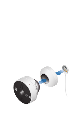
Magnetic Mounting
1. Attach the UVC‑Micro Camera and the
power cable to the UVC‑Micro Base.
Page 8
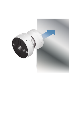
2. Attach the camera assembly to a
metal (steel) surface.
*640-00157-02*
640-00157-02
Page 9
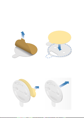
Mounting with Tape
1. Remove the paper from one side of
the Mounting Tape, and center the
tape on the back of the Flat Base Plate.
2. Remove the paper from the other
side of the Mounting Tape and attach
the Flat Base Plate to the surface.
Page 10
Wall Mounting with Screws
1. Place the Flat Base Plate at the desired
location and mark the two mounting
holes.
Note: If you are running the power
cable inside the ceiling or wall,
then mark the cable feed opening
below the mounting holes.
Page 11

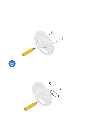
2. Use a 3 mm drill bit to drill a hole at
each mark, and insert a Screw Anchor
into each hole.
3. (Optional) When running the power
cable inside the wall or ceiling, cut the
hole for the power cable. Then feed
the cable through the hole and the
Flat Base Plate.
Page 12

4. Attach the Flat Base Plate to the
surface by fastening a Screw to each
Screw Anchor.
Page 13

Corner Mounting with Screws
1. Place the Corner Base Plate at the
desired location and mark the two
mounting holes.
2. Use a 3 mm drill bit to drill a hole at
each mark, and insert a Screw Anchor
into each hole.
Page 14

3. Feed the power cable through the
back of the Corner Base Plate.
4. Secure the Corner Base Plate by
fastening a Screw to each Screw
Anchor.
Page 15

Attaching the Camera
1. Attach the power cable to the back of
the UVC‑Micro Base.
2. Connect the UVC‑Micro Base to the
Base Plate by inserting the mounting
tabs into the slots on the base.
Page 16

3. Rotate the UVC‑Micro Base to lock it.
4. Attach the UVC‑Micro Camera to the
UVC‑Micro Base, and pivot the camera
to the desired angle.
Page 17

5. Plug the Power Adapter into a power
outlet. To secure the connection, use
the outlet cover plate screw to fasten
the Power Adapter to the outlet.
(Recommended)
Note: (6) Cable Clips with adhesive
tape are included to help hold
the power cable in place. Remove
the paper backing on each clip to
expose the adhesive tape.
Page 18

Set Up the UVC Micro
Ensure you are running the latest version
of UniFi Video, v3.1.1 or higher (UniFi NVR
or computer‑based system).
Download the UniFi Video User Guide for
detailed information on how to set up
and use UniFi Video:
documentation.ubnt.com/unifivideo
UniFi Video Mobile App
For quick setup, a mobile app is available.
Install the UniFi Video app, and follow the
on-screen instructions:
• iOS: iTunes App Store
• Android: Google Play Store
Page 19

Specifications
UVC-Micro
Dimensions
Weight 53 g (1.87 oz)
Network Interface 2.4/5 GHz Dual-Band Wi-Fi
Sensor
Lens EFL=2.38 mm / F2.4
View Angle 79.13° (H), 54.15° (V), 88.45° (D)
Night Mode
Video Compression H.264
Resolution 720p HD (1280 x 720)
Max. Frame Rate 30 FPS
Microphone Yes
Speaker* Yes
Power Supply
Max. Power
Consumption
Mounting Wall/Ceiling/Corner Kit
Operating Temperature 0 to 35° C (32 to 95° F)
Operating Humidity 20 to 90% Noncondensing
* Functionality coming soon with a software update
40.7 x 40.7 x 40.8 mm
(1.61 x1.61 x 1.61")
Progressive Scan
RGB CMOS 1/4"
Infrared LEDs with
Mechanical IR Cut Filter
5.5V (5,5V) Adapter with
Extendable Power Cable
3.2W
Page 20

Safety Notices
1. Read, follow, and keep instructions.
2. Heed all warnings.
3. Only use attachments/accessories specified by
the manufacturer.
WARNING: Do not use this
product in a location that can be
submerged by water.
WARNING: Avoid using this
product during an electrical
storm. There may be a remote risk
of electric shock from lightning.
Page 21

Electrical Safety Information
1. Compliance is required with respect to voltage,
frequency, and current requirements indicated
on the manufacturer’s label. Connection to a
different power source than those specified
may result in improper operation, damage
to the equipment or pose a fire hazard if the
limitations are not followed.
2. There are no operator serviceable parts inside
this equipment. Service should be provided only
by a qualified service technician.
3. Contact a qualified electrician or the
manufacturer if there are questions about the
installation prior to connecting the equipment.
4. Protective bonding must be installed in
accordance with local national wiring rules and
regulations.
Page 22

Limited Warranty
UBIQUITI NETWORKS, Inc (“UBIQUITI NETWORKS”)
warrants that the product(s) furnished hereunder
(the “Product(s)”) shall be free from defects in
material and workmanship for a period of one
(1) year from the date of shipment by UBIQUITI
NETWORKS under normal use and operation.
UBIQUITI NETWORKS’ sole and exclusive obligation
and liability under the foregoing warranty shall
be for UBIQUITI NETWORKS, at its discretion, to
repair or replace any Product that fails to conform
to the above warranty during the above warranty
period. The expense of removal and reinstallation
of any Product is not included in this warranty. The
warranty period of any repaired or replaced Product
shall not extend beyond its original term.
Page 23

Warranty Conditions
The above warranty does not apply if the Product:
(I) has been modified and/or altered, or an
addition made thereto, except by Ubiquiti
Networks, or Ubiquiti Networks’ authorized
representatives, or as approved by Ubiquiti
Networks in writing;
(II) has been painted, rebranded or physically
modified in any way;
(III) has been damaged due to errors or defects
in cabling;
(IV) has been subjected to misuse, abuse,
negligence, abnormal physical,
electromagnetic or electrical stress, including
lightning strikes, or accident;
(V) has been damaged or impaired as a result of
using third party firmware;
(VI) has no original Ubiquiti MAC label, or is missing
any other original Ubiquiti label(s); or
(VII) has not been received by Ubiquiti within
30days of issuance of the RMA.
In addition, the above warranty shall apply only if:
the product has been properly installed and used at
all times in accordance, and in all material respects,
with the applicable Product documentation.
Page 24

Returns
No Products will be accepted for replacement
or repair without obtaining a Return Materials
Authorization (RMA) number from UBIQUITI
NETWORKS during the warranty period, and the
Products being received at UBIQUITI NETWORKS’
facility freight prepaid in accordance with the RMA
process of UBIQUITI NETWORKS. Products returned
without an RMA number will not be processed and
will be returned freight collect or subject to disposal.
Information on the RMA process and obtaining an
RMA number can be found at:
www.ubnt.com/support/warranty
Disclaimer
EXCEPT FOR ANY EXPRESS WARRANTIES PROVIDED
HEREIN, UBIQUITI NETWORKS, ITS AFFILIATES,
AND ITS AND THEIR THIRD PARTY DATA, SERVICE,
SOFTWARE AND HARDWARE PROVIDERS HEREBY
DISCLAIM AND MAKE NO OTHER REPRESENTATION
OR WARRANTY OF ANY KIND, EXPRESS, IMPLIED
OR STATUTORY, INCLUDING, BUT NOT LIMITED TO,
REPRESENTATIONS, GUARANTEES, OR WARRANTIES
OF MERCHANTABILITY, ACCURACY, QUALITY OF
SERVICE OR RESULTS, AVAILABILITY, SATISFACTORY
QUALITY, LACK OF VIRUSES, QUIET ENJOYMENT,
FITNESS FOR A PARTICULAR PURPOSE AND
NON‑INFRINGEMENT AND ANY WARRANTIES
ARISING FROM ANY COURSE OF DEALING, USAGE
OR TRADE PRACTICE IN CONNECTION WITH SUCH
PRODUCTS AND SERVICES. BUYER ACKNOWLEDGES
Page 25

THAT NEITHER UBIQUITI NETWORKS NOR ITS
THIRD PARTY PROVIDERS CONTROL BUYER’S
EQUIPMENT OR THE TRANSFER OF DATA OVER
COMMUNICATIONS FACILITIES, INCLUDING THE
INTERNET, AND THAT THE PRODUCTS AND SERVICES
MAY BE SUBJECT TO LIMITATIONS, INTERRUPTIONS,
DELAYS, CANCELLATIONS AND OTHER PROBLEMS
INHERENT IN THE USE OF COMMUNICATIONS
FACILITIES. UBIQUITI NETWORKS, ITS AFFILIATES
AND ITS AND THEIR THIRD PARTY PROVIDERS
ARE NOT RESPONSIBLE FOR ANY INTERRUPTIONS,
DELAYS, CANCELLATIONS, DELIVERY FAILURES,
DATA LOSS, CONTENT CORRUPTION, PACKET LOSS,
OR OTHER DAMAGE RESULTING FROM ANY OF THE
FOREGOING. In addition, UBIQUITI NETWORKS does
not warrant that the operation of the Products will
be error‑free or that operation will be uninterrupted.
In no event shall UBIQUITI NETWORKS be
responsible for damages or claims of any nature
or description relating to system performance,
including coverage, buyer’s selection of products
(including the Products) for buyer’s application and/
or failure of products (including the Products) to
meet government or regulatory requirements.
Page 26

Limitation of Liability
EXCEPT TO THE EXTENT PROHIBITED BY LOCAL LAW,
IN NO EVENT WILL UBIQUITI OR ITS SUBSIDIARIES,
AFFILIATES OR SUPPLIERS BE LIABLE FOR DIRECT,
SPECIAL, INCIDENTAL, CONSEQUENTIAL OR OTHER
DAMAGES (INCLUDING LOST PROFIT, LOST DATA,
OR DOWNTIME COSTS), ARISING OUT OF THE USE,
INABILITY TO USE, OR THE RESULTS OF USE OF
THE PRODUCT, WHETHER BASED IN WARRANTY,
CONTRACT, TORT OR OTHER LEGAL THEORY, AND
WHETHER OR NOT ADVISED OF THE POSSIBILITY OF
SUCH DAMAGES.
Note
Some countries, states and provinces do not allow
exclusions of implied warranties or conditions, so
the above exclusion may not apply to you. You
may have other rights that vary from country to
country, state to state, or province to province.
Some countries, states and provinces do not allow
the exclusion or limitation of liability for incidental
or consequential damages, so the above limitation
may not apply to you. EXCEPT TO THE EXTENT
ALLOWED BY LOCAL LAW, THESE WARRANTY TERMS
DO NOT EXCLUDE, RESTRICT OR MODIFY, AND ARE
IN ADDITION TO, THE MANDATORY STATUTORY
RIGHTS APPLICABLE TO THE LICENSE OF ANY
SOFTWARE (EMBEDDED IN THE PRODUCT) TO YOU.
The United Nations Convention on Contracts for the
International Sale of Goods shall not apply to any
transactions regarding the sale of the Products.
Page 27

Compliance
FCC
Changes or modifications not expressly approved by
the party responsible for compliance could void the
user’s authority to operate the equipment.
This device complies with Part 15 of the FCC Rules.
Operation is subject to the following two conditions.
1. This device may not cause harmful interference,
and
2. This device must accept any interference
received, including interference that may cause
undesired operation.
This equipment has been tested and found to
comply with the limits for a Class B digital device,
pursuant to Part 15 of the FCC Rules. These limits are
designed to provide reasonable protection against
harmful interference in a residential installation. This
equipment generates, uses and can radiate radio
frequency energy and, if not installed and used in
accordance with the instructions, may cause harmful
interference to radio communications. However,
there is no guarantee that interference will not occur
in a particular installation. If this equipment does
cause harmful interference to radio or television
reception, which can be determined by turning the
equipment off and on, the user is encouraged to try
to correct the interference by one or more of the
following measures:
Page 28

• Reorient or relocate the receiving antenna.
• Increase the separation between the equipment
and receiver.
• Connect the equipment into an outlet on a
circuit different from that to which the receiver
is connected.
• Consult the dealer or an experienced radio/TV
technician for help.
Operations of this equipment in a residential area
is likely to cause harmful interference in which case
the user will be required to correct the interference
at his own expense.
This radio transmitter FCC ID: SWX‑MICRO has been
approved by FCC to operate with the antenna types
listed below with the maximum permissible gain
and required antenna impedance for each antenna
type indicated. Antenna types not included in this
list, having a gain greater than the maximum gain
indicated for that type, are strictly prohibited for use
with this device.
Antenna type: metal antenna, Gain: 1 dBi
Industry Canada
CAN ICES-3(B)/NMB-3(B)
To reduce potential radio interference to other
users, the antenna type and its gain should be so
chosen that the equivalent isotropically radiated
power (e.i.r.p.) is not more than that permitted for
successful communication.
Page 29

This device complies with Industry Canada licence‑
exempt RSS standard(s). Operation is subject to the
following two conditions:
1. This device may not cause interference, and
2. This device must accept any interference,
including interference that may cause undesired
operation of the device.
This radio transmitter (IC: 6545A‑MICRO) has been
approved by Industry Canada to operate with the
antenna types listed below with the maximum
permissible gain and required antenna impedance
for each antenna type indicated. Antenna types not
included in this list, having a gain greater than the
maximum gain indicated for that type, are strictly
prohibited for use with this device.
Antenna type: metal antenna, Gain: 1 dBi
CAN ICES-3(B)/NMB-3(B)
Pour réduire le risque d’interférence aux autres
utilisateurs, le type d’antenne et son gain doivent
être choisies de façon que la puissance isotrope
rayonnée équivalente (PIRE) ne dépasse pas ce qui
est nécessaire pour une communication réussie.
Cet appareil est conforme à la norme RSS Industrie
Canada exempts de licence norme(s). Son
fonctionnement est soumis aux deux conditions
suivantes:
Page 30

1. Cet appareil ne peut pas provoquer
d’interférences et
2. Cet appareil doit accepter toute interférence, y
compris les interférences qui peuvent causer un
mauvais fonctionnement du dispositif.
Cet émetteur radio (IC: 6545A‑MICRO) a été
approuvée par Industrie Canada pour l’exploitation
avec l’antenne types énumérés ci‑dessous avec le
gain maximal admissible et requis l’impédance de
l’antenne pour chaque type d’antenne indiqué.
Types d’antenne non inclus dans cette liste, ayant
un gain supérieur au gain maximal indiqué pour ce
type, sont strictement interdits pour une utilisation
avec cet appareil. Immédiatement suite à la
remarque, le fabricant doit fournir une liste de tous
les types d’antenne approuvé pour une utilisation
avec l’émetteur, ce qui indique le gain maximal
d’antenne permis (en dBi) et requis d’impédance
pour chacun.
Type d’antenne: antenne métallique, Gain: 1 dBi
RF Exposure Warning
The antennas used for this transmitter must be
installed to provide a separation distance of at least
20 cm from all persons and must not be located or
operating in conjunction with any other antenna
or transmitter, except as listed for this product’s
certification.
Page 31

Les antennes utilisées pour cet émetteur doit être
installé pour fournir une distance de séparation d’au
moins 20 cm de toutes les personnes et ne doit pas
être situé ou opérant en conjonction avec une autre
antenne ou un autre émetteur, sauf dans les cas
énumérés à la certification de ce produit.
CE Marking
CE marking on this product represents theproduct is
in compliance with all directives that are applicable
to it.
Online Resources
Support support.ubnt.com
Community community.ubnt.com
Downloads downloads.ubnt.com
Page 32

©2015 Ubiquiti Networks, Inc. All rights reserved. Ubiquiti,
Ubiquiti Networks, the Ubiquiti U logo, the Ubiquiti beam
logo, and UniFi are trademarks or registered trademarks
of Ubiquiti Networks, Inc. in the United States and in other
countries. All other trademarks are the property of their
respective owners.
PH072115
 Loading...