

Page 1
1080p Indoor/Outdoor
IP Camera with Infrared
and Optical Zoom
Model: UVC-G3-PRO
Page 2
Introduction
Thank you for purchasing the Ubiquiti
Networks® UniFi Video® G3 Pro Camera.
This Quick Start Guide is designed to guide
you through installation and also includes
warranty terms.
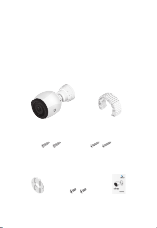
Package Contents
UVC-G3-PRO Tightening Tool
Screw Anchors
(Qty. 2)
Pole Mount
Bracket
Self-Tapping Screws
Machine Screws
(Qty. 2)
(Qty. 2)
1080p Indoor/Outdoor
IP Camera with Infrared
and Optical Zoom
Model: UVC-G3-PRO
Quick Start
Guide
Page 3

Installation Requirements
• Pole-mounting: Two metal straps (not
included)
• Shielded Category 5 (or above) cabling with
drain wire should be used for all outdoor
wired Ethernet connections and should
be grounded through the AC ground of
the PoE.
We recommend that you protect
your networks from harmful outdoor
environments and destructive ESD events
with industrial-grade, shielded Ethernet
cable from Ubiquiti Networks. For more
details, visit www.ubnt.com/toughcable
• Surge protection should be used for all
outdoor installations. We recommend that
you use two Ethernet Surge Protectors,
model ETH-SP, one near the camera and the
other at the entry point to the building. The
ETH-SP will absorb power surges and safely
discharge them into the ground.
Page 4
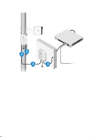
UVC-G3-PRO
US-8-150W
ETH-SP
ETH-SP
Diagram Showing Use of Ethernet Surge Protectors
TERMS OF USE: All Ethernet cabling runs must use CAT5 (or
above). Shielded Ethernet cable and earth grounding must
be used for outdoor installations as conditions of product
warranty. TOUGHCable
is the professional installer’s responsibility to follow local country
regulations.
™
is designed for outdoor installations. It
To LAN
Page 5
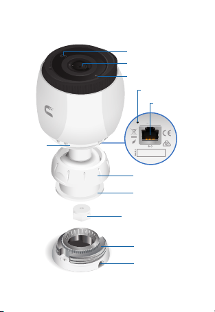
Hardware Overview
48V 0.5A PoE
M/N: UVC-G3-PRO
Compliant
RoHS
RESET
Camera
Ring
Ambient Light Sensor
Camera Lens
Microphone
Reset Button
Ethernet Port
Tilt/Mount Ring
Adjustable Base
Cable Gland
Mounting Base
Cable Slot
Page 6

Ethernet 10/100 RJ45 port connects to an
802.3af/802.3at PoE switch for PoE power
and data.
Reset Button To reset to factory defaults,
press and hold the Reset button for more than
10 seconds while the camera is poweredon.
Before You Begin
Remove the sticker from the bottom of the
Mounting Base.
Installation Overview
To install the camera, please follow the
instructions of the following sections in this
order:
1. Hardware Installation
2. Connecting Power over Ethernet
3. UniFi Video
4. Adjusting the Camera View
Hardware Installation
The camera can be mounted on a wall, ceiling,
or pole. Follow the appropriate steps for your
installation:
Page 7
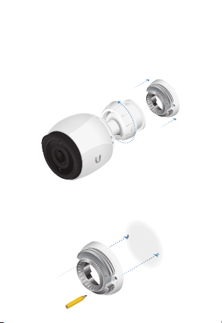
Wall/Ceiling Mount
1. Remove the Mounting Base from the
camera by turning the Tilt/Mount Ring
counterclockwise.
2. Mark the mounting holes on the wall or
ceiling.
Page 8
Note: If you are running the cable along
the wall or ceiling, position the Cable
Slot towards the direction you want the
cabling to run. For outdoor installations,
position the Cable Slot downward.
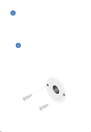
3. Use a 7 mm (¼") drill bit to drill the
mounting holes in the wall or ceiling.
Note: If
you are running the Ethernet
cable through the wall, cut a hole
centered between the mounting
holes that is large enough to feed the
cable through.
4. Insert a Screw Anchor into each mounting
hole.
Page 9
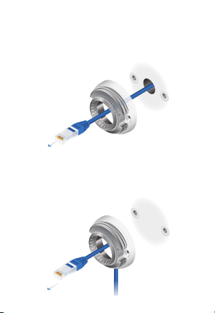
5. If you are feeding the Ethernet cable
through the wall or ceiling, do so now and
feed it through the Mounting Base.
If not, feed the Ethernet cable through the
Mounting Base and place the cable in the
Cable Slot.
Page 10
IMPORTANT: If
camera outdoors, create a drip loop for
the cable below the camera to prevent
water ingress.
6. Fasten the Mounting Base to the wall or
ceiling using two Self-Tapping Screws.
7. Remove the camera from the Adjustable
Base by turning the Camera Ring in the
direction shown.
you are installing your
Page 11
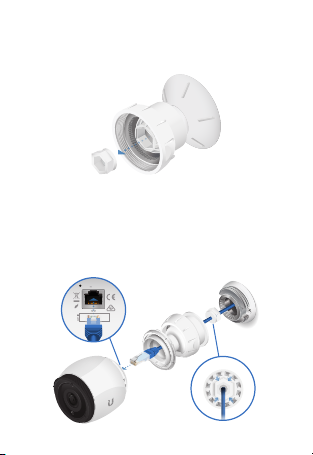
8. Remove the Cable Gland from the
48V 0.5A PoE
M/N: UVC-G3-PRO
Compliant
RoHS
RESET
Adjustable Base.
9. Feed the Ethernet cable through the Cable
Gland and Adjustable Base. Seal the Cable
Gland in place by firmly pressing around
its edges. Then connect the cable to the
Ethernet Port on the camera.
Page 12
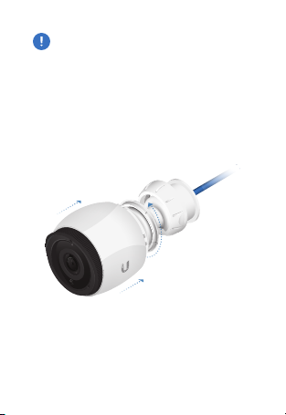
IMPORTANT: For proper weather sealing,
the Cable Gland must fit securely within
the Adjustable Base when the camera is
mounted. Ensure that the Cable Gland is
securely seated during installation and
cable routing.
10. Connect the camera back to the Adjustable
Base by turning the Camera Ring in the
direction shown.
Page 13

11. Orient the camera to the desired position
while connecting the Adjustable Base to
the Mounting Base.
Note: You will fine-tune and then
lock the positioning after you check
the camera view in the UniFi Video
software.
12. Proceed to the Connecting Power over
Ethernet section.
Page 14

Pole Mount
To mount the camera on a pole, two metal
straps are required (not included).
1. Feed the metal straps through the slots on
the Pole Mount Bracket.
2. Wrap a metal strap around the pole and
tighten it by turning the screw clockwise.
Repeat for the second strap.
Page 15

3. Remove the Mounting Base from the
camera by turning the Tilt/Mount Ring
counterclockwise.
4. Feed the Ethernet cable through the
Mounting Base.
Page 16

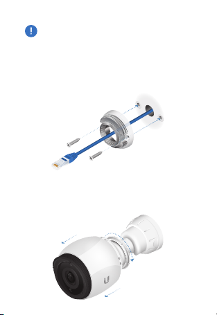
5. Fasten the Mounting Base to the Pole
Mount Bracket using two Machine Screws.
6. Remove the camera from the Adjustable
Base by turning the Camera Ring in the
direction shown.
Page 17

7. Remove the Cable Gland from the
48V 0.5A PoE
M/N: UVC-G3-PRO
Compliant
RoHS
RESET
Adjustable Base.
8. Feed the Ethernet cable through the Cable
Gland and Adjustable Base. Seal the Cable
Gland in place by firmly pressing around
its edges. Then connect the cable to the
Ethernet Port on the camera.
Page 18

IMPORTANT: For proper weather sealing,
the Cable Gland must fit securely within
the Adjustable Base when the camera is
mounted. Ensure that the Cable Gland is
securely seated during installation and
cable routing.
9. Connect the camera back to the Adjustable
Base by turning the Camera Ring in the
direction shown.
Page 19

10. Orient the camera to the desired position
while connecting the Adjustable Base to
the Mounting Base.
Note:
Fine-tune and then lock the
positioning after you check the camera
view in the UniFi Video software.
Page 20

Connecting Power over Ethernet
1 3 5 7 9 11 13 15 17 19 21 22
2 4 6 8 10 12 14 16 18 20 22 24
1 3 5 7 9 11 13 15 17 19 21 22
2 4 6 8 10 12 14 16 18 20 22 24
SFP1
SFP2
The camera features auto-sensing
802.3af/802.3at PoE and can be powered by
any 802.3af/802.3at PoE compliant switch,
such as a UniFi PoE Switch.
Connect the Ethernet cable from the camera
directly to a PoE port on the switch.
*640-00316-06*
640-00316-06
Page 21

UniFi Video
Ensure that you are running UniFiVideo
software version 3.9 or newer. The latest
version of the UniFi Video software is available
at www.ubnt.com/download/unifivideo
The UniFi Video auto-management feature
should automatically detect your new
camera(s). To manage the camera:
1. Click the Unmanaged tab.
2. Select the camera row.
Page 22

3. The Camera Details window will appear
on the right side of the screen. Enter ubnt
in the Username and Password fields and
click Manage.
4. UniFi Video will automatically update the
camera’s firmware (this may take up to
five minutes). Then the camera will appear
in the Managed cameras list. Check the
camera view and proceed to the Adjusting
the Camera View section.
Page 23

UniFi Video App
The UniFi Video app is available
from the AppStore (iOS) or
Google Play™ (Android).
For details on using the UniFi Video software,
refer to the User Guide at:
www.ubnt.com/download/unifivideo
Page 24

Adjusting the Camera View
1. Fine-tune the positioning as you check the
camera preview in the software.
2. Ensure that the arrow side of the included
Tightening Tool faces the camera. Then
insert the Tightening Tool between the
camera and AdjustableBase.
Arrow
3. Fit the Tightening Tool to the camera.
Page 25

4. Turn the Tightening Tool to tighten the
Camera Ring.
5. Move the Tightening Tool to fit the
Tilt/Mount Ring.
6. Secure the Tilt/Mount Ring to lock the
positioning and complete installation.
Page 26

Specifications
Dimensions
(Without Mounting
Plate)
Weight
(Without Mounting
Plate)
Enclosure UV Stabilized Polycarbonate
Networking
Interface
Sensor Sony IMX290, 1/2.8"
Lens 3-9 mm, f/1.2-f/2.1 Powered
Field of View
Wide
Tele
Night Mode IR LEDs with Mechanical IR
Video Compression H.264
Resolution 1080p Full HD (1920 x 1080)
Maximum Frame
Rate
UVC-G3-PRO
Ø 86 x 153 mm (Ø 3.39 x 6.02")
700 g (1.54 lb)
and Die-Cast Aluminum
(1) 10/100 Ethernet Port
108° (H), 58° (V), 125° (D)
37° (H), 20° (V), 43° (D)
Zoom Lens
Cut Filter
30 FPS
Page 27

Image Settings Flip, Brightness, Contrast,
Management
Interface
Managed Mode
Standalone Mode
Microphone Yes
Max. Power
Consumption
Power Method IEEE 802.3af/802.3at PoE
Power Supply 802.3af/802.3at PoE Switch
Buttons Factory Reset Button
Mounting Wall/Ceiling (Kits Included)
Operating
Temperature
Operating Humidity 0 to 90% Noncondensing
WDR, Hue, Infrared,
Sharpness, Saturation,
Denoise, 50/60 Hz Flicker
UniFi Video v3.9 or Newer
Camera Integrated Web UI
Reduction
12.5W
Pole (Bracket Included)
-20 to 50° C
-4 to 122° F
Page 28

Safety Notices
1. Read, follow, and keep these instructions.
2. Heed all warnings.
3. Only use attachments/accessories specified by the
manufacturer.
WARNING: This product may become
hot during operation. Exercise caution
when handling.
WARNING: Do not use this product in
a location that can be submerged by
water.
WARNING: Avoid using this product
during an electrical storm. There may
be a remote risk of electric shock from
lightning.
Electrical Safety Information
1. Compliance is required with respect to voltage,
frequency, and current requirements indicated on the
manufacturer’s label. Connection to a different power
source than those specified may result in improper
operation, damage to the equipment or pose a fire
hazard if the limitations are not followed.
2. There are no operator serviceable parts inside this
equipment. Service should be provided only by a
qualified service technician.
Page 29

Limited Warranty
UBIQUITI NETWORKS, Inc (“UBIQUITI NETWORKS”) warrants
that the product(s) furnished hereunder (the “Product(s)”)
shall be free from defects in material and workmanship for a
period of one (1) year from the date of shipment by UBIQUITI
NETWORKS under normal use and operation. UBIQUITI
NETWORKS’ sole and exclusive obligation and liability under
the foregoing warranty shall be for UBIQUITI NETWORKS, at
its discretion, to repair or replace any Product that fails to
conform to the above warranty during the above warranty
period. The expense of removal and reinstallation of any
Product is not included in this warranty. The warranty period
of any repaired or replaced Product shall not extend beyond
its original term.
Warranty Conditions
The above warranty does not apply if the Product:
(I) has been modified and/or altered, or an addition
made thereto, except by Ubiquiti Networks, or Ubiquiti
Networks’ authorized representatives, or as approved
by Ubiquiti Networks in writing;
(II) has been painted, rebranded or physically modified
in any way;
(III) has been damaged due to errors or defects in cabling;
(IV) has been subjected to misuse, abuse, negligence,
abnormal physical, electromagnetic or electrical stress,
including lightning strikes, or accident;
(V) has been damaged or impaired as a result of using
third party firmware;
(VI) has no original Ubiquiti MAC label, or is missing any
other original Ubiquiti label(s); or
(VII) has not been received by Ubiquiti within 30 days of
issuance of the RMA.
Page 30

In addition, the above warranty shall apply only if: the
product has been properly installed and used at all times in
accordance, and in all material respects, with the applicable
Product documentation; all Ethernet cabling runs use CAT5
(or above), and for outdoor installations, shielded Ethernet
cabling is used, and for indoor installations, indoor cabling
requirements are followed.
Returns
No Products will be accepted for replacement or repair
without obtaining a Return Materials Authorization (RMA)
number from UBIQUITI NETWORKS during the warranty
period, and the Products being received at UBIQUITI
NETWORKS’ facility freight prepaid in accordance with the
RMA process of UBIQUITI NETWORKS. Products returned
without an RMA number will not be processed and will be
returned freight collect or subject to disposal. Information on
the RMA process and obtaining an RMA number can be found
at: www.ubnt.com/support/warranty
Disclaimer
EXCEPT FOR ANY EXPRESS WARRANTIES PROVIDED HEREIN,
UBIQUITI NETWORKS, ITS AFFILIATES, AND ITS AND THEIR
THIRD PARTY DATA, SERVICE, SOFTWARE AND HARDWARE
PROVIDERS HEREBY DISCLAIM AND MAKE NO OTHER
REPRESENTATION OR WARRANTY OF ANY KIND, EXPRESS,
IMPLIED OR STATUTORY, INCLUDING, BUT NOT LIMITED
TO, REPRESENTATIONS, GUARANTEES, OR WARRANTIES OF
MERCHANTABILITY, ACCURACY, QUALITY OF SERVICE OR
RESULTS, AVAILABILITY, SATISFACTORY QUALITY, LACK OF
VIRUSES, QUIET ENJOYMENT, FITNESS FOR A PARTICULAR
PURPOSE AND NON-INFRINGEMENT AND ANY WARRANTIES
ARISING FROM ANY COURSE OF DEALING, USAGE OR
TRADE PRACTICE IN CONNECTION WITH SUCH PRODUCTS
Page 31

AND SERVICES. BUYER ACKNOWLEDGES THAT NEITHER
UBIQUITI NETWORKS NOR ITS THIRD PARTY PROVIDERS
CONTROL BUYER’S EQUIPMENT OR THE TRANSFER OF
DATA OVER COMMUNICATIONS FACILITIES, INCLUDING THE
INTERNET, AND THAT THE PRODUCTS AND SERVICES MAY
BE SUBJECT TO LIMITATIONS, INTERRUPTIONS, DELAYS,
CANCELLATIONS AND OTHER PROBLEMS INHERENT IN
THE USE OF COMMUNICATIONS FACILITIES. UBIQUITI
NETWORKS, ITS AFFILIATES AND ITS AND THEIR THIRD PARTY
PROVIDERS ARE NOT RESPONSIBLE FOR ANY INTERRUPTIONS,
DELAYS, CANCELLATIONS, DELIVERY FAILURES, DATA LOSS,
CONTENT CORRUPTION, PACKET LOSS, OR OTHER DAMAGE
RESULTING FROM ANY OF THE FOREGOING. In addition,
UBIQUITI NETWORKS does not warrant that the operation
of the Products will be error-free or that operation will
be uninterrupted. In no event shall UBIQUITI NETWORKS
be responsible for damages or claims of any nature or
description relating to system performance, including
coverage, buyer’s selection of products (including the
Products) for buyer’s application and/or failure of products
(including the Products) to meet government or regulatory
requirements.
Limitation of Liability
EXCEPT TO THE EXTENT PROHIBITED BY LOCAL LAW, IN NO
EVENT WILL UBIQUITI OR ITS SUBSIDIARIES, AFFILIATES OR
SUPPLIERS BE LIABLE FOR DIRECT, SPECIAL, INCIDENTAL,
CONSEQUENTIAL OR OTHER DAMAGES (INCLUDING LOST
PROFIT, LOST DATA, OR DOWNTIME COSTS), ARISING OUT OF
THE USE, INABILITY TO USE, OR THE RESULTS OF USE OF THE
PRODUCT, WHETHER BASED IN WARRANTY, CONTRACT, TORT
OR OTHER LEGAL THEORY, AND WHETHER OR NOT ADVISED
OF THE POSSIBILITY OF SUCH DAMAGES.
Page 32

Note
Some countries, states and provinces do not allow exclusions
of implied warranties or conditions, so the above exclusion
may not apply to you. You may have other rights that
vary from country to country, state to state, or province
to province. Some countries, states and provinces do not
allow the exclusion or limitation of liability for incidental or
consequential damages, so the above limitation may not
apply to you. EXCEPT TO THE EXTENT ALLOWED BY LOCAL
LAW, THESE WARRANTY TERMS DO NOT EXCLUDE, RESTRICT
OR MODIFY, AND ARE IN ADDITION TO, THE MANDATORY
STATUTORY RIGHTS APPLICABLE TO THE LICENSE OF ANY
SOFTWARE (EMBEDDED IN THE PRODUCT) TO YOU. The
United Nations Convention on Contracts for the International
Sale of Goods shall not apply to any transactions regarding
the sale of the Products.
Compliance
FCC
Changes or modifications not expressly approved by the
party responsible for compliance could void the user‘s
authority to operate the equipment.
This device complies with part 15 of the FCC Rules. Operation
is subject to the following two conditions:
1. This device may not cause harmful interference, and
2. This device must accept any interference received,
including interference that may cause undesired
operation.
This equipment has been tested and found to comply
with the limits for a Class A digital device, pursuant to part
15 of the FCC Rules. These limits are designed to provide
Page 33

reasonable protection against harmful interference when the
equipment is operated in a commercial environment. This
equipment generates, uses, and can radiate radio frequency
energy and, if not installed and used in accordance with the
instruction manual, may cause harmful interference to radio
communications. Operation of this equipment in a residential
area is likely to cause harmful interference in which case
the user will be required to correct the interference at his
own expense.
ISED Canada
CAN ICES-3(A)/NMB-3(A)
This Class A digital apparatus complies with Canadian CAN
ICES-003.
CAN ICES-3(A)/NMB-3(A)
Cet appareil numérique de la classe A est conforme à la
norme NMB-003 du Canada.
CE Marking
CE marking on this product represents the product is in
compliance with all directives that are applicable to it.
Australia and New Zealand
Warning: This is a Class A product. In a domestic
environment this product may cause radio
interference in which case the user may be required
to take adequate measures.
Page 34

RoHS/WEEE Compliance Statement
English
European Directive 2012/19/EU requires that the equipment
bearing this symbol on the product and/or its packaging
must not be disposed of with unsorted municipal waste.
The symbol indicates that this product should be disposed
of separately from regular household waste streams. It is
your responsibility to dispose of this and other electric and
electronic equipment via designated collection facilities
appointed by the government or local authorities. Correct
disposal and recycling will help prevent potential negative
consequences to the environment and human health. For
more detailed information about the disposal of your old
equipment, please contact your local authorities, waste
disposal service, or the shop where you purchased the
product.
Deutsch
Die Europäische Richtlinie 2012/19/EU verlangt, dass
technische Ausrüstung, die direkt am Gerät und/oder an der
Verpackung mit diesem Symbol versehen ist, nicht zusammen
mit unsortiertem Gemeindeabfall entsorgt werden darf. Das
Symbol weist darauf hin, dass das Produkt von regulärem
Haushaltmüll getrennt entsorgt werden sollte. Es liegt in Ihrer
Verantwortung, dieses Gerät und andere elektrische und
elektronische Geräte über die dafür zuständigen und von
der Regierung oder örtlichen Behörden dazu bestimmten
Sammelstellen zu entsorgen. Ordnungsgemäßes Entsorgen
und Recyceln trägt dazu bei, potentielle negative Folgen
Page 35

für Umwelt und die menschliche Gesundheit zu vermeiden.
Wenn Sie weitere Informationen zur Entsorgung Ihrer
Altgeräte benötigen, wenden Sie sich bitte an die örtlichen
Behörden oder städtischen Entsorgungsdienste oder an den
Händler, bei dem Sie das Produkt erworben haben.
Español
La Directiva 2012/19/UE exige que los equipos que lleven
este símbolo en el propio aparato y/o en su embalaje no
deben eliminarse junto con otros residuos urbanos no
seleccionados. El símbolo indica que el producto en cuestión
debe separarse de los residuos domésticos convencionales
con vistas a su eliminación. Es responsabilidad suya desechar
este y cualesquiera otros aparatos eléctricos y electrónicos a
través de los puntos de recogida que ponen a su disposición
el gobierno y las autoridades locales. Al desechar y reciclar
correctamente estos aparatos estará contribuyendo a evitar
posibles consecuencias negativas para el medio ambiente y
la salud de las personas. Si desea obtener información más
detallada sobre la eliminación segura de su aparato usado,
consulte a las autoridades locales, al servicio de recogida y
eliminación de residuos de su zona o pregunte en la tienda
donde adquirió el producto.
Français
La directive européenne 2012/19/UE exige que l’équipement
sur lequel est apposé ce symbole sur le produit et/ou son
emballage ne soit pas jeté avec les autres ordures ménagères.
Ce symbole indique que le produit doit être éliminé dans un
circuit distinct de celui pour les déchets des ménages. Il est
de votre responsabilité de jeter ce matériel ainsi que tout
autre matériel électrique ou électronique par les moyens de
collecte indiqués par le gouvernement et les pouvoirs publics
des collectivités territoriales. L’élimination et le recyclage en
Page 36

bonne et due forme ont pour but de lutter contre l’impact
néfaste potentiel de ce type de produits sur l’environnement
et la santé publique. Pour plus d’informations sur le mode
d’élimination de votre ancien équipement, veuillez prendre
contact avec les pouvoirs publics locaux, le service de
traitement des déchets, ou l’endroit où vous avez acheté
le produit.
Italiano
La direttiva europea 2012/19/UE richiede che le
apparecchiature contrassegnate con questo simbolo sul
prodotto e/o sull’imballaggio non siano smaltite insieme ai
rifiuti urbani non differenziati. Il simbolo indica che questo
prodotto non deve essere smaltito insieme ai normali rifiuti
domestici. È responsabilità del proprietario smaltire sia questi
prodotti sia le altre apparecchiature elettriche ed elettroniche
mediante le specifiche strutture di raccolta indicate dal
governo o dagli enti pubblici locali. Il corretto smaltimento
ed il riciclaggio aiuteranno a prevenire conseguenze
potenzialmente negative per l’ambiente e per la salute
dell’essere umano. Per ricevere informazioni più dettagliate
circa lo smaltimento delle vecchie apparecchiature in
Vostro possesso, Vi invitiamo a contattare gli enti pubblici di
competenza, il servizio di smaltimento rifiuti o il negozio nel
quale avete acquistato il prodotto.
Page 37

Declaration of Conformity
български [Bulgarian] С настоящото UBIQUITI NETWORKS
декларира, че това устройство UVC-G3-PRO е в съответствие
със съществените изисквания и други приложими разпоредби
на Директиви 2014/30/ЕС, 2014/35/ЕС. Цялостният текст на ЕС
декларацията за съответствие може да се намери на следния
интернет адрес:
www.ubnt.com/compliance
Hrvatski [Croatian] UBIQUITI NETWORKS ovim putem izjavljuje da
je ovaj uređaj UVC-G3-PRO sukladan osnovnim zahtjevima i ostalim
bitnim odredbama Direktiva 2014/30/EU, 2014/35/EU. Cjeloviti tekst
EU izjave o sukladnosti dostupan je na sljedećoj internetskoj adresi:
www.ubnt.com/compliance
Čeština [Czech] UBIQUITI NETWORKS tímto prohlašuje, že toto
UVC-G3-PRO zařízení, je ve shodě se základními požadavky a dalšími
příslušnými ustanoveními směrnic 2014/30/EU, 2014/35/EU. Úplné
znění EU prohlášení o shodě je k dispozici na této internetové adrese:
www.ubnt.com/compliance
Dansk [Danish] Hermed, UBIQUITI NETWORKS, erklærer at denne
UVC-G3-PRO enhed, er i overensstemmelse med de væsentlige
krav og øvrige relevante krav i direktiver 2014/30/EU, 2014/35/EU.
EU-overensstemmelseserklæringens fulde tekst kan findes på følgende
internetadresse:
www.ubnt.com/compliance
Nederlands [Dutch] Hierbij verklaart UBIQUITI NET WORKS, dat deze
UVC-G3-PRO apparaat, in overeenstemming is met de essentiële
eisen en de andere relevante bepalingen van richtlijnen 2014/30/EU,
2014/35/EU. De volledige tekst van de EU-conformiteitsverklaring
kan worden geraadpleegd op het volgende internetadres:
www.ubnt.com/compliance
English
Hereby, UBIQUITI NETWORKS, declares that this UVC-G3-PRO
device, is in compliance with the essential requirements and other
relevant provisions of Directives
of the EU declaration of conformity is available at the following internet
address: www.ubnt.com/compliance
Eesti keel [Estonian] Käesolevaga UBIQUITI NETWORKS kinnitab,
et antud UVC-G3-PRO seade, on vastavus olulistele nõuetele ja
teistele asjakohastele sätetele direktiivide 2014/30/EL, 2014/35/EL.
ELi vastavusdeklaratsiooni täielik tekst on kättesaadav järgmisel
internetiaadressil:
2014/30/EU, 2014/35/EU
www.ubnt.com/compliance
. The full text
Page 38

Suomi [Finnish] Täten UBIQUITI NETWORKS vakuuttaa, että tämä
UVC-G3-PRO laite, on yhdenmukainen olennaisten vaatimusten
ja muiden sitä koskevien direktiivien 2014/30/EU, 2014/35/EU.
EU-vaatimustenmukaisuusvakuutuksen täysimittainen teksti on
saatavilla seuraavassa internetosoitteessa:
Français [French] Par la présente UBIQUITI NETWORKS déclare que
l’appareil UVC-G3-PRO, est conforme aux exigences essentielles et aux
autres dispositions pertinentes des directives 2014/30/UE, 2014/35/UE.
Le texte complet de la déclaration UE de conformité est disponible à
l’adresse internet suivante:
Deutsch [German] Hiermit erklärt UBIQUITI NET WORKS, dass sich
dieses UVC-G3-PRO Gerät, in Übereinstimmung mit den grundlegenden
Anforderungen und den anderen relevanten Vorschriften der
Richtlinien 2014/30/EU, 2014/35/EU befindet. Der vollständige Text
der EU-Konformitätserklärung ist unter der folgenden Internetadresse
verfügbar:
www.ubnt.com/compliance
Ελληνικά [Greek] Δια του παρόντος, UBIQUITI NETWORKS,
δηλώνει ότι αυτή η συσκευή UVC-G3-PRO, είναι σε συμμόρφωση
με τις βασικές απαιτήσεις και τις λοιπές σχετικές διατάξεις των
οδηγιών 2014/30/EE, 2014/35/EE. Το πλήρες κείμενο της δήλωσης
συμμόρφωσης ΕΕ διατίθεται στην ακόλουθη ιστοσελίδα στο διαδίκτυο:
www.ubnt.com/compliance
Magyar [Hungarian] Ezennel UBIQUITI NETWORKS kijelenti, hogy ez
a UVC-G3-PRO készülék megfelel az alapvető követelményeknek és
más vonatkozó 2014/30/EU, 2014/35/EU irányelvek rendelkezéseit.
Az EU-megfelelőségi nyilatkozat teljes szövege elérhető a következő
internetes címen:
www.ubnt.com/compliance
Íslenska [Icelandic] Hér, UBIQUITI NETWORKS, því yfir að þetta
UVC-G3-PRO tæki er í samræmi við grunnkröfur og önnur
viðeigandi ákvæði tilskipana 2014/30/ESB, 2014/35/ESB. Fullur
texti ESB samræmisyfirlýsing er að finna á eftirfarandi netfangi:
www.ubnt.com/compliance
Italiano [Italian] Con la presente, UBIQUITI NETWORKS, dichiara che
questo dispositivo UVC-G3-PRO, è conforme ai requisiti essenziali ed
alle altre disposizioni pertinenti delle direttive 2014/30/UE, 2014/35/UE.
Il testo completo della dichiarazione di conformità UE è disponibile al
seguente indirizzo Internet:
www.ubnt.com/compliance
www.ubnt.com/compliance
www.ubnt.com/compliance
Page 39

Latviešu valoda [Latvian] Ar šo, UBIQUITI NETWORKS, deklarē, ka
UVC-G3-PRO ierīce, ir saskaņā ar būtiskajām prasībām un citiem
attiecīgiem noteikumiem Direktīvās 2014/30/ES, 2014/35/ES. Pilns
ES atbilstības deklarācijas teksts ir pieejams šādā interneta vietnē:
www.ubnt.com/compliance
Lietuvių kalba [Lithuanian] UBIQUITI NETWORKS dek laruoja, kad šis
UVC-G3-PRO įrenginys atitinka esminius reikalavimus ir kitas 2014/30/ES,
2014/35/ES Direktyvų nuostatas. Visas ES atitikties deklaracijos tekstas
prieinamas šiuo interneto adresu:
Malti [Maltese]
dan il-mezz UVC-G3-PRO huwa konformi mar-rekwiżiti essenzjali
u dispożizzjonijiet rilevanti oħrajn ta ‘Direttivi 2014/30/UE,
2014/35/UE. Id-dikjarazzjoni tal-konformità tista’ tiġi kkonsultata minn
www.ubnt.com/compliance
Norsk [Norwegian]
UVC-G3-PRO enheten, er i samsvar med de grunnleggende kravene og
andre relevante bestemmelser i direktivene 2014/30/EU, 2014/35/EU.
Den fulle teksten til EU-samsvarserklæringen er tilgjengelig på
følgende internettadresse: www.ubnt.com/compliance
Polski [Polish] Niniejszym, Ubiquiti Networks, oświadcza, że
urządzenie UVC-G3-PRO, jest zgodny z zasadniczymi wymaganiami
oraz pozostałymi stosownymi postanowieniami Dyrektyw
2014/35/UE
. Pełny tekst deklaracji zgodności UE jest dostępny pod
następującym adresem internetowym:
Português [Portuguese] UBIQUITI NETWORKS declara que este
dispositivo UVC-G3-PRO, está conforme com os requisitos essenciais
e outras disposições das Directivas
integral da declaração de conformidade está disponível no seguinte
endereço de Internet:
Română [Romanian] Prin prezenta, UBIQUITI NETWORKS declară că
acest dispozitiv UVC-G3-PRO este în conformitate cu cerințele esențiale
și alte prevederi relevante ale Directivelor
Textul integral al declarației UE de conformitate este disponibil la
următoarea adresă internet:
Slovenčina [Slovak]
UVC-G3-PRO zariadenie, je v súlade so základnými požiadavkami a
ďalšími relevantnými ustanoveniami smernice 2014/30/EÚ, 2014/35/EÚ
Úplné EÚ vyhlásenie o zhode je k dispozícii na tejto internetovej adrese:
www.ubnt.com/compliance
www.ubnt.com/compliance
Hawnhekk, UBIQUITI NETWORKS, tiddikjara li
Herved UBIQUITI NETWORKS, erklærer at denne
www.ubnt.com/compliance
2014/30/UE, 2014/35/UE
www.ubnt.com/compliance
2014/30/UE, 2014/35/UE
www.ubnt.com/compliance
Týmto UBIQUITI NETWORKS, prehlasuje, že toto
2014/30/UE,
. O texto
.
.
Page 40

Slovenščina [Slovenian]
je naprava UVC-G3-PRO v skladu z obveznimi zahtevami in drugimi
ustreznimi določbami direktiv 2014/30/EU in 2014/35/EU. Celotno
besedilo izjave EU o skladnosti je na voljo na naslednjem spletnem
naslovu: www.ubnt.com/compliance
Español [Spanish] Por medio de la presente UBIQUITI NETWORKS
declara que este dispositivo UVC-G3-PRO, cumple con los requisitos
esenciales y cualesquiera otras disposiciones aplicables o exigibles
de las Directivas
declaración UE de conformidad está disponible en la dirección Internet
siguiente:
Svenska [Swedish] Härmed UBIQUITI NETWORKS, intygar att denna
UVC-G3-PRO enhet är i överensstämmelse med de väsentliga
egenskapskrav och övriga relevanta bestämmelser som framgår
av direktiven
EU-försäkran om överensstämmelse finns på följande webbadress:
www.ubnt.com/compliance
Družba UBIQUITI NETWORKS izjavlja, da
2014/30/UE, 2014/35/UE
www.ubnt.com/compliance
2014/30/EU, 2014/35/EU
. El texto completo de la
. Den fullständiga texten till
Online Resources
Website www.ubnt.com
Support help.ubnt.com
Community community.ubnt.com
Downloads downloads.ubnt.com
Ubiquiti Networks, Inc.
685 Third Avenue, 27th Floor
New York, NY 10017
©2017 Ubiquiti Networks, Inc. All rights reserved. Ubiquiti, Ubiquiti Networks, the Ubiquiti U
logo, the Ubiquiti beam logo, UniFi, and UniFi Video are trademarks or registered trademarks
of Ubiquiti Networks, Inc. in the United States and in other countries. Apple and the Apple logo
are trademarks of Apple Inc., registered in the U.S. and other countries. App Store is a service
mark of Apple Inc. Android, Google, Google Play, the Google Play logo and other marks are
trademarks of Google Inc. All other trademarks are the property of their respective owners.
USA
JL122617
 Loading...