

Page 1
1080p Indoor/Outdoor IP Camera with
Infrared and 802.3af Support
Model: UVC-G3-FLEX
Page 2
Introduction
Thank you for purchasing the Ubiquiti Networks® G3 Flex
camera. This Quick Start Guide is designed to guide you
through installation and includes warranty terms.
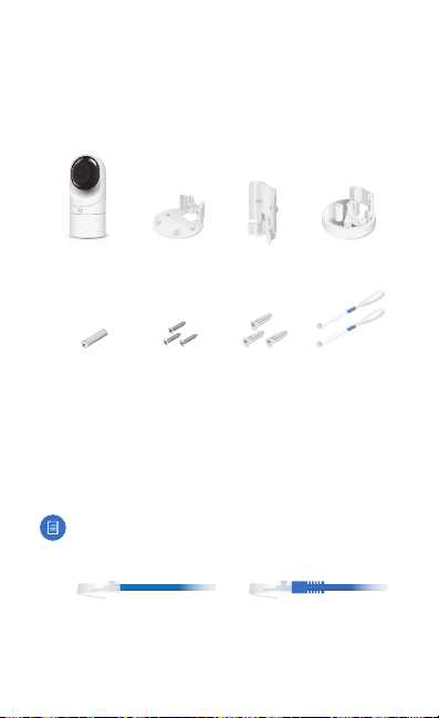
Package Contents
G3 Flex Camera Flush Mount Pole/Wall
Security Screw
(Qty. 1)
Screws
(Qty. 3)
Mount
Screw Anchors
(Qty. 3)
Outdoor
Cover
Zip Ties
(Qty. 2)
Installation Requirements
• Phillips screwdriver
• Drill and 6 mm (1/4") bit for drywall anchors and 3 mm (1/8")
for screws)
• Category 5e (or above) Ethernet cable
Note:
When using the Outdoor Cover, use an Ethernetcable
without a strain-relief boot on the connector. This willprevent
unnecessary tension on the cable ends during installation.
Cable without a strain-relief boot Cable with a strain-relief boot
TERMS OF USE: All Ethernet cabling runs must use CAT5e (or above). Shielded Ethernet
cable and earth grounding must be used for outdoor installations as conditions of product
warranty. TOUGHCable™ is designed for outdoor installations. It is the professional installer’s
responsibility to follow local country regulations.
Page 3
Outdoor Installation Requirements
IMPORTANT: When installed outdoors, the camera must be
installed in the upright postion only.
• Mounting location should be at least 60 cm (2 ft) from the
edge of the eave or ceiling.
• Mount the camera in the upright position only. Please see
diagram below.
• Shielded Category 5e (or above) cabling with drain wire
should be used for all outdoor wired Ethernet connections
and should be grounded through the AC ground of the PoE.
We recommend that you protect your networks from
harmful outdoor environments and destructive ESD events
with industrial‑grade, shielded Ethernet cable from Ubiquiti
Networks. For more details, visit www.ubnt.com/toughcable
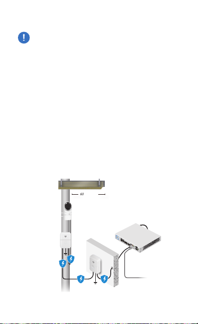
• Surge protection should be used for all outdoor installations.
We recommend that you use two Ethernet Surge Protectors,
model ETH‑SP‑G2, one near the UVC‑G3‑Flex and the other
at the entry point to the building. The ETH‑SP‑G2 will absorb
power surges and safely discharge them into the ground.
60 cm (2 ft)
UVC-G3-FLEX
US-8-150W
ETH-SP-G2
ETH-SP-G2
To LAN
Diagram Showing Use of Ethernet Surge Protectors
Page 4
Before You Begin
The UVC G3 Flex camera is designed to work with Ubiquiti's
new integrated management system, UniFi Protect.
UniFi Protect is a flexible and powerful IP video surveillance
system that can manage UniFi Protect cameras and the UniFi
Protect mobile app. The software is free from all hosting and
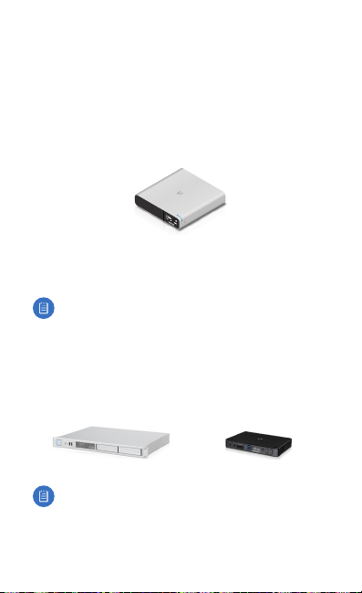
licensing fees and comes pre‑installed on UniFi's Cloud Key Gen2
Plus, model UCK‑G2‑PLUS.
UniFi Cloud Key Gen2 Plus, model UCK-G2-PLUS
For more information on UniFi Protect, visit us on the web at:
unifi-protect.ubnt.com
Note: The UVC G3 Flex camera will also work with the
UniFi Video® 3 controller software.
UniFi Video may be hosted on any of the following:
• UniFi Application Server, model UAS‑XG
• UniFi NVR, model UVC‑NVR‑2TB
• A Linux or Windows computer
UniFi Application Server, model UAS-XG UniFi NVR, model UVC-NVR-2TB
Note: The latest UniFi Video 3 software, for Linux‑ or
Windows‑based computers, is available for free
download at: www.ubnt.com/download/unifivideo
Page 5
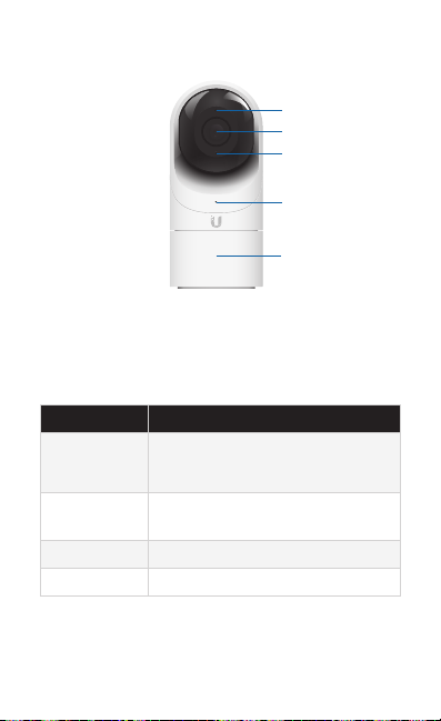
Hardware Overview
Microphone
Camera Lens
Light Sensor
LED
Swivel Base
Microphone Microphone for recording audio
Camera Lens Lens for viewing/recording video
Light Sensor Sensor for ambient light detection
LED Status indicator for the following:
LED State Status
Alternating
White/Blue
Steady Blue Connected to UniFi Video Controller;
Flashing Green Disconnected from Controller
Steady White Awaiting adoption
Swivel Base Allows you to change the viewing angle of the
camera by adjusting left or right. Useful if mounted on a wall
or other permanent surface.
Device is busy; do not touch or unplug it.
This usually indicates that a process such
as a firmware upgrade is taking place.
Reset Button Pressed
Page 6
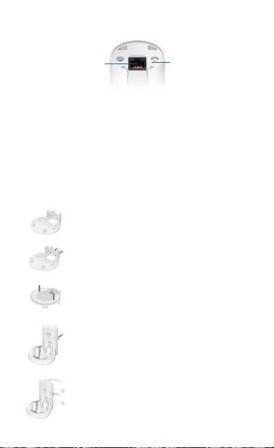
Bottom View
Ethernet Port
Ethernet Port The Ethernet Port is a 10/100 Mbps port used
to supply power from a PoE 802.3af‑compliant switch to the
camera. The switch should be connected to a LAN running
DHCP services and the UniFi Video Controller software.
Reset Button The Reset Button is used to reset the camera to
factory defaults. Press and hold the Reset Button for more than
10 seconds while the camera is powered on.
Reset Button
Mounting Options
Use the Flush Mount by itself to install the G3 Flex
camera on a desktop or tabletop. Out of the box,
this mount comes preinstalled on the camera.
Use the Flush Mount with two screws to install
the G3 Flex camera on a wall (vertically).
Use the Flush Mount with two screws to install
the G3 Flex camera on a solid horizontal surface
or ceiling.
Use the Pole Mount with two screws and the
Outdoor Cover to install the G3 Flex camera on a
wall or at surface outdoors. The Outdoor Cover is
not required for indoor installations.
Use the Pole Mount with two plastic zip ties and
the Outdoor Cover to install the G3 Flex camera
on an outdoor pole. The Outdoor Cover is not
required for indoor pole installations.
Page 7
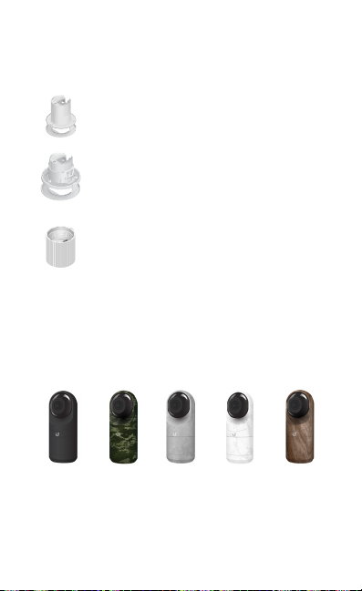
Additional Mounts Available
There are two additional mounts available for the G3 Flex: a
Ceiling Mount and a Pendant Mount. Each is sold separately.
Use the optional Ceiling Mount, Screw Kit, and
Mount Cover to install the G3 Flex camera on a
solid horizontal surface or ceiling.
Use the optional Ceiling Mount, Mount Cover, and
Back Plate Assembly to install the G3 Flex camera
on a drop tile ceiling or horizontal surface
where the interior side of the Ceiling Mount is
accessible.
Use the Pendant Mount to install the G3 Flex
camera onto a tted 3/4" or 1.5" conduit mount
or ceiling pipe.
Optional Covers
There are also optional skin covers available to enhance the
look of the G3 Flex camera and allow it to discreetly blend
into the setting or environment it is installed in. Choose from
one of the following design patterns: Black, Camouflage,
Concrete, Marble, and Wood.
Black Camoflauge Concrete Marble Wood
Page 8
Installation
The UVC G3 Flex can be installed using one of the following
methods:
• Desktop For installing on a flat surface such as a desktop
or table/shelf; could be set up for temporary installations.
• Wall/Ceiling For installing in a secure location; used more
for stationary or permanent installations.
• Pole For installing on a pole (indoor or outdoor).
Proceed to the appropriate section for your installation.
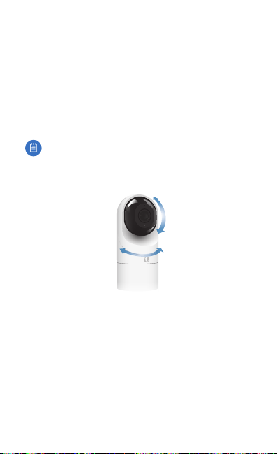
Note: The viewing angle or surveillance coverage of the
G3 Flex camera can be changed at any time.
• Tilt the lens up or down for vertical adjustment
• Turn the base left or right for horizontal adjustment
Page 9
Desktop/Table
1. Remove the Flush Mount from the base of the camera.
2. Inser t one end of the RJ‑45 cable into the Ethernet Port and the
other end into a PoE 802.3af‑compliant switch.
3. Attach the camera to the Flush Mount by lining up the
notches with the slots in the base of the camera. Press
firmly together until the camera is secure.
Note: Ensure the Ethernet cable is seated in the notch
between the Flush Mount and base of the camera.
Page 10

4. Place the camera on a desk or table in its upright position.
5. Adjust the viewing angle or surveillance coverage as
needed by following these steps:
• Tilt the lens up or down to adjust the angle vertically
• Turn the camera body left or right to adjust the angle
horizontally
Installation complete.
Desktop / Table Install
Page 11

Indoor Wall/Ceiling
1. If the Ethernet cable is coming from the inside of a wall:
a. Drill or cut a hole in the wall and feed the Ethernet
cable through the opening.
b. Pull the Ethernet cable forward and slide it through the
opening in the mount.
2. Use the Screws and Screw Anchors to secure the Flush
Mount to the wall.
or
Top Side Down Mounting
3. Connect the Ethernet cable to the Ethernet Port in the base
of the camera.
Vertical Upright Mounting
Page 12

4. Attach the camera to the Flush Mount by lining up the
notches with the slots in the base of the camera. Press
firmly together until the camera is secure.
or
Vertical mounting on ceiling
Installation complete.
Horizozntal Surface / Ceiling with Flush Mount
Vertical mounting on a wall
Indoor Wall with Flush Mount
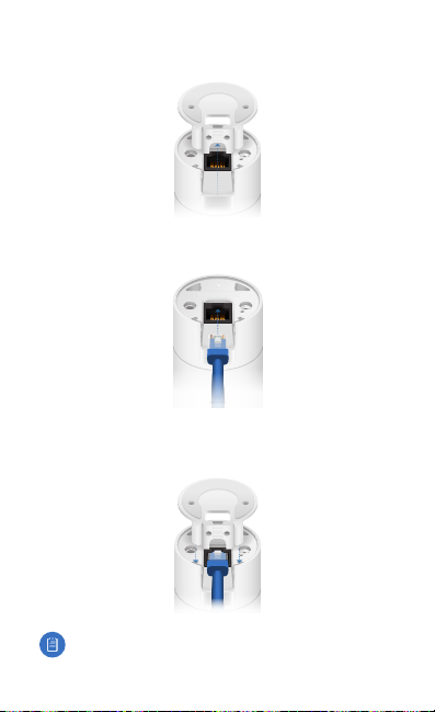
Page 13

Pole
Note: If you are mounting the camera outdoors, it must
be installed in the upright position to prevent water
from getting into the base of the camera. Use the
OutdoorCover for additional protection from moisture.
1. Attach the Pole Mount to a pole using the included Zip Ties.
2. Insert and pull an Ethernet cable through the back port
opening of the Outdoor Cover.
Note: When using the Outdoor Cover, use an Ethernet
cable without strain‑relief boots on the connector. This
will prevent unnecessary tension on the cable ends.
3. Connect the Ethernet cable to the Ethernet Port on the
G3 Flex camera.
Page 14

4. Attach the camera to the Outdoor Cover by lining up the
notches with the slots on the bottom of the camera. Press
firmly until the camera snaps on.
5. Attach the camera to the Pole Mount:
a. Press the camera against the Pole Mount and line up
the notches on the mount with the slots on the
bottom of the camera.
b. Slide the camera down onto the Pole Mount until it
is secure.
Note: When using the Outdoor Cover, use an Ethernet
cable without strain‑relief boots on the connector. This
will prevent unnecessary tension on the cable ends.
Page 15

6. Use a phillips screwdriver to install the Security Screw
through the Outdoor Cover and into the base of the
camera. This helps secrure the camera to the mount.
7. Adjust the camera to the desired viewing angle by:
• Tilting the lens up or down for vertical adjustment
• Turn the camera body left or right to adjust the angle
horizontally
Installation is complete.
Pole Mount Install
Page 16

Setting Up UniFi Protect via App
Download and install the UniFi Protect app to configure the
UVC‑G3‑Flex.
Note: When you first launch UniFi Protect, the app will
prompt you to enable Bluetooth and other relevant
features necessary to provide the best user experience
possible. Please allow these features and permissions
to take place for proper app functionality.
1. Launch the UniFi Protect app.
Page 17

2. Tap the side menu in the upper‑left corner of the app to
access additional options.
3. Tap Add Cameras to add a new camera.
Note: If setting up multiple cameras, UniFi Protect
allows you to add more than one camera during the
setup process.
4. When the Select cameras screen appears, tap each camera
in the list you would like to add to your UniFi Protect
system. Tap Set up cameras to continue.
Page 18

5. A Name your camera screen appears individually for each
camera you selected in step 4. Enter a name for each
camera and tap Next, repeating this process until all
cameras have been named.
6. If necessary, any camera requiring a firmware upgrade will
update at this time. Once completed, a live view of each
camera will display in the app.
UVC G3 FLEX
Page 19

UniFi Video App
Note: For UniFi Video 3 deployments, there is a
UniFi Video mobile app available for download
in the App Store for iOS devices and Google Play™
store for Android‑based devices.
For details on using the UniFi Video software, refer to the User
Guide at: www.ubnt.com/download/unifivideo
Page 20

Specifications
Dimensions Ø 107.5 x 48 x 48 mm
Weight
Sensor 1/2.7" 2‑Megapixel HDR Sensor
Lens EFL 4mm / f2.0
Viewing Angle with Lens
Distortion Correction (LDC)
LDC Off
LDC On
Night Mode IR LEDs with Mechanical ICR Filter
Video Compression H.264
Resolution 1080p FHD (1920 x 1080)
Maximum Frame Rate 25 FPS
Image Settings Brightness, Contrast, Sharpness, Saturation,
Microphone
Management Interface UniFi Protect; UniFi Video
Networking Interface (1) 10/100 Ethernet Port
Max. Power Consumption 4W
Power Method 802.3af PoE
Power Supply 802.3af PoE Switch Port
Mounting Table, Wall (Indoor/Outdoor), Pole
Operating Temperature ‑20 to 50° C
Operating Humidity 20 to 90% Noncondensing
UVC‑G3‑FLEX
(Ø 4.23 x 1.89 x 1.89")
170 g (5.99 oz)
87.4° (H), 47° (V), 104° (D)
80° (H), 46° (V), 92° (D)
Noise Reduction, 50/60 Hz
(‑4 to 122° F)
Yes
Page 21

Safety Notices
1. Read, follow, and keep these instructions.
2. Heed all warnings.
3. Only use attachments/accessories specified by the manufacturer.
WARNING: Hot Surface. Do not touch.
WARNING: Do not use this product in a location that can
be submerged by water.
WARNING: Avoid using this product during an electrical
storm. There may be a remote risk of electric shock from
lightning.
Electrical Safety Information
1. Compliance is required with respect to voltage, frequency, and current
requirements indicated on the manufacturer’s label. Connection to a
different power source than those specified may result in improper
operation, damage to the equipment or pose a fire hazard if the
limitations are not followed.
2. There are no operator serviceable parts inside this equipment. Service
should be provided only by a qualified service technician.
Page 22

Limited Warranty
UBIQUITI NETWORKS, Inc (“UBIQUITI NETWORKS”) warrants that the
product(s) furnished hereunder (the “Product(s)”) shall be free from defects
in material and workmanship for a period of one (1) year from the date
of shipment by UBIQUITI NETWORKS under normal use and operation.
UBIQUITI NETWORKS’ sole and exclusive obligation and liability under
the foregoing warranty shall be for UBIQUITI NETWORKS, at its discretion,
to repair or replace any Product that fails to conform to the above
warranty during the above warranty period. The expense of removal and
reinstallation of any Product is not included in this warranty. The warranty
period of any repaired or replaced Product shall not extend beyond its
original term.
Warranty Conditions
The above warranty does not apply if the Product:
(I) has been modified and/or altered, or an addition made thereto,
except by Ubiquiti Networks, or Ubiquiti Networks’ authorized
representatives, or as approved by Ubiquiti Networks in writing;
(II) has been painted, rebranded or physically modified in any way;
(III) has been damaged due to errors or defects in cabling;
(IV) has been subjected to misuse, abuse, negligence, abnormal
physical, electromagnetic or electrical stress, including lightning
strikes, or accident;
(V) has been damaged or impaired as a result of using third party
firmware;
(VI) has no original Ubiquiti MAC label, or is missing any other original
Ubiquiti label(s); or
(VII) has not been received by Ubiquiti within 30 days of issuance of
the RMA.
In addition, the above warranty shall apply only if: the product has been
properly installed and used at all times in accordance, and in all material
respects, with the applicable Product documentation; all Ethernet cabling
runs use CAT5 (or above), and for outdoor installations, shielded Ethernet
cabling is used, and for indoor installations, indoor cabling requirements
are followed.
Returns
No Products will be accepted for replacement or repair without obtaining
a Return Materials Authorization (RMA) number from UBIQUITI NETWORKS
during the warranty period, and the Products being received at UBIQUITI
NETWORKS’ facility freight prepaid in accordance with the RMA process of
UBIQUITI NETWORKS. Products returned without an RMA number will not
be processed and will be returned freight collect or subject to disposal.
Information on the RMA process and obtaining an RMA number can be
found at: www.ubnt.com/support/warranty
Page 23

Disclaimer
EXCEPT FOR ANY EXPRESS WARRANTIES PROVIDED HEREIN, UBIQUITI
NETWORKS, ITS AFFILIATES, AND ITS AND THEIR THIRD PARTY DATA,
SERVICE, SOFTWARE AND HARDWARE PROVIDERS HEREBY DISCLAIM
AND MAKE NO OTHER REPRESENTATION OR WARRANTY OF ANY KIND,
EXPRESS, IMPLIED OR STATUTORY, INCLUDING, BUT NOT LIMITED TO,
REPRESENTATIONS, GUARANTEES, OR WARRANTIES OF MERCHANTABILITY,
ACCURACY, QUALITY OF SERVICE OR RESULTS, AVAILABILITY,
SATISFACTORY QUALITY, LACK OF VIRUSES, QUIET ENJOYMENT, FITNESS
FOR A PARTICULAR PURPOSE AND NON‑INFRINGEMENT AND ANY
WARRANTIES ARISING FROM ANY COURSE OF DEALING, USAGE OR
TRADE PRACTICE IN CONNECTION WITH SUCH PRODUCTS AND SERVICES.
BUYER ACKNOWLEDGES THAT NEITHER UBIQUITI NETWORKS NOR
ITS THIRD PARTY PROVIDERS CONTROL BUYER’S EQUIPMENT OR THE
TRANSFER OF DATA OVER COMMUNICATIONS FACILITIES, INCLUDING
THE INTERNET, AND THAT THE PRODUCTS AND SERVICES MAY BE
SUBJECT TO LIMITATIONS, INTERRUPTIONS, DELAYS, CANCELLATIONS
AND OTHER PROBLEMS INHERENT IN THE USE OF COMMUNICATIONS
FACILITIES. UBIQUITI NETWORKS, ITS AFFILIATES AND ITS AND THEIR THIRD
PARTY PROVIDERS ARE NOT RESPONSIBLE FOR ANY INTERRUPTIONS,
DELAYS, CANCELLATIONS, DELIVERY FAILURES, DATA LOSS, CONTENT
CORRUPTION, PACKET LOSS, OR OTHER DAMAGE RESULTING FROM ANY
OF THE FOREGOING. In addition, UBIQUITI NETWORKS does not warrant
that the operation of the Products will be error‑free or that operation will
be uninterrupted. In no event shall UBIQUITI NETWORKS be responsible
for damages or claims of any nature or description relating to system
performance, including coverage, buyer’s selection of products (including
the Products) for buyer’s application and/or failure of products (including
the Products) to meet government or regulatory requirements.
Limitation of Liability
EXCEPT TO THE EXTENT PROHIBITED BY LOCAL LAW, IN NO EVENT WILL
UBIQUITI OR ITS SUBSIDIARIES, AFFILIATES OR SUPPLIERS BE LIABLE FOR
DIRECT, SPECIAL, INCIDENTAL, CONSEQUENTIAL OR OTHER DAMAGES
(INCLUDING LOST PROFIT, LOST DATA, OR DOWNTIME COSTS), ARISING
OUT OF THE USE, INABILITY TO USE, OR THE RESULTS OF USE OF THE
PRODUCT, WHETHER BASED IN WARRANTY, CONTRACT, TORT OR OTHER
LEGAL THEORY, AND WHETHER OR NOT ADVISED OF THE POSSIBILITY OF
SUCH DAMAGES.
Page 24

Note
Some countries, states and provinces do not allow exclusions of implied
warranties or conditions, so the above exclusion may not apply to you.
You may have other rights that vary from country to country, state to
state, or province to province. Some countries, states and provinces do not
allow the exclusion or limitation of liability for incidental or consequential
damages, so the above limitation may not apply to you. EXCEPT TO
THE EXTENT ALLOWED BY LOCAL LAW, THESE WARRANTY TERMS DO
NOT EXCLUDE, RESTRICT OR MODIFY, AND ARE IN ADDITION TO, THE
MANDATORY STATUTORY RIGHTS APPLICABLE TO THE LICENSE OF ANY
SOFTWARE (EMBEDDED IN THE PRODUCT) TO YOU. The United Nations
Convention on Contracts for the International Sale of Goods shall not apply
to any transactions regarding the sale of the Products.
Compliance
FCC
Changes or modifications not expressly approved by the party responsible
for compliance could void the user’s authority to operate the equipment.
This device complies with Part 15 of the FCC Rules. Operation is subject to
the following two conditions:
1. This device may not cause harmful interference, and
2. This device must accept any interference received, including
interference that may cause undesired operation.
NOTE: This equipment has been tested and found to comply with the
limits for a Class A digital device, pursuant to part 15 of the FCC Rules.
These limits are designed to provide reasonable protection against
harmful interference when the equipment is operated in a commercial
environment. This equipment generates, uses, and can radiate radio
frequency energy and, if not installed and used in accordance with
the instruction manual, may cause harmful interference to radio
communications. Operations of this equipment in a residential area is likely
to cause harmful interference in which case the user will be required to
correct the interference at his own expense.
Industry Canada
CAN ICES‑3(A)/NMB‑3(A)
This Class A digital apparatus complies with Canadian ICES‑003.
CAN ICES‑3(A)/NMB‑3(A)
Cet appareil numérique de la classe A est conforme à la norme NMB‑003
du Canada.
Page 25

CE Marking
CE marking on this product represents the product is in compliance with all
directives that are applicable to it.
RoHS/WEEE Compliance Statement
English
European Directive 2012/19/EU requires that the equipment bearing
this symbol on the product and/or its packaging must not be disposed
of with unsorted municipal waste. The symbol indicates that this
product should be disposed of separately from regular household waste
streams. It is your responsibility to dispose of this and other electric and
electronic equipment via designated collection facilities appointed by the
government or local authorities. Correct disposal and recycling will help
prevent potential negative consequences to the environment and human
health. For more detailed information about the disposal of your old
equipment, please contact your local authorities, waste disposal service, or
the shop where you purchased the product.
Deutsch
Die Europäische Richtlinie 2012/19/EU verlangt, dass technische
Ausrüstung, die direkt am Gerät und/oder an der Verpackung mit diesem
Symbol versehen ist, nicht zusammen mit unsortiertem Gemeindeabfall
entsorgt werden darf. Das Symbol weist darauf hin, dass das Produkt
von regulärem Haushaltmüll getrennt entsorgt werden sollte. Es
liegt in Ihrer Verantwortung, dieses Gerät und andere elektrische
und elektronische Geräte über die dafür zuständigen und von der
Regierung oder örtlichen Behörden dazu bestimmten Sammelstellen zu
entsorgen. Ordnungsgemäßes Entsorgen und Recyceln trägt dazu bei,
potentielle negative Folgen für Umwelt und die menschliche Gesundheit
zu vermeiden. Wenn Sie weitere Informationen zur Entsorgung Ihrer
Altgeräte benötigen, wenden Sie sich bitte an die örtlichen Behörden oder
städtischen Entsorgungsdienste oder an den Händler, bei dem Sie das
Produkt erworben haben.
Page 26

Español
La Directiva 2012/19/UE exige que los equipos que lleven este símbolo en
el propio aparato y/o en su embalaje no deben eliminarse junto con otros
residuos urbanos no seleccionados. El símbolo indica que el producto
en cuestión debe separarse de los residuos domésticos convencionales
con vistas a su eliminación. Es responsabilidad suya desechar este y
cualesquiera otros aparatos eléctricos y electrónicos a través de los puntos
de recogida que ponen a su disposición el gobierno y las autoridades
locales. Al desechar y reciclar correctamente estos aparatos estará
contribuyendo a evitar posibles consecuencias negativas para el medio
ambiente y la salud de las personas. Si desea obtener información más
detallada sobre la eliminación segura de su aparato usado, consulte a las
autoridades locales, al servicio de recogida y eliminación de residuos de su
zona o pregunte en la tienda donde adquirió el producto.
Français
La directive européenne 2012/19/UE exige que l’équipement sur lequel
est apposé ce symbole sur le produit et/ou son emballage ne soit pas jeté
avec les autres ordures ménagères. Ce symbole indique que le produit
doit être éliminé dans un circuit distinct de celui pour les déchets des
ménages. Il est de votre responsabilité de jeter ce matériel ainsi que tout
autre matériel électrique ou électronique par les moyens de collecte
indiqués par le gouvernement et les pouvoirs publics des collectivités
territoriales. L’élimination et le recyclage en bonne et due forme ont pour
but de lutter contre l’impact néfaste potentiel de ce type de produits
sur l’environnement et la santé publique. Pour plus d’informations sur le
mode d’élimination de votre ancien équipement, veuillez prendre contact
avec les pouvoirs publics locaux, le service de traitement des déchets, ou
l’endroit où vous avez acheté le produit.
Italiano
La direttiva europea 2012/19/UE richiede che le apparecchiature
contrassegnate con questo simbolo sul prodotto e/o sull’imballaggio non
siano smaltite insieme ai rifiuti urbani non differenziati. Il simbolo indica
che questo prodotto non deve essere smaltito insieme ai normali rifiuti
FLEXstici. È responsabilità del proprietario smaltire sia questi prodotti sia
le altre apparecchiature elettriche ed elettroniche mediante le specifiche
strutture di raccolta indicate dal governo o dagli enti pubblici locali. Il
corretto smaltimento ed il riciclaggio aiuteranno a prevenire conseguenze
potenzialmente negative per l’ambiente e per la salute dell’essere umano.
Per ricevere informazioni più dettagliate circa lo smaltimento delle vecchie
apparecchiature in Vostro possesso, Vi invitiamo a contattare gli enti
pubblici di competenza, il servizio di smaltimento rifiuti o il negozio nel
quale avete acquistato il prodotto.
Page 27

Declaration of Conformity
български [Bulgarian] С настоящото UBIQUITI NETWORKS декларира, че този тип радиосъоръжение
UVC-G3-FLEX е в съответствие с Директива 2014/53/ЕС. Цялостният текст на ЕС декларацията за
съответствие може да се намери на следния интернет адрес:
Hrvatski [Croatian] UBIQUITI NETWORKS ovime izjavljuje da je radijska oprema tipa UVC-G3-FLEX
u skladu s Direktivom 2014/53/EU. Cjeloviti tekst EU izjave o sukladnosti dostupan je na sljedećoj
internetskoj adresi:
www.ubnt.com/compliance
Čeština [Czech] Tímto UBIQUITI NETWORKS prohlašuje, že typ rádiového zařízení UVC-G3-FLEX je v
souladu se směrnicí 2014/53/EU. Úplné znění EU prohlášení o shodě je k dispozici na této internetové
adrese:
www.ubnt.com/compliance
Dansk [Danish] Hermed erklærer UBIQUITI NETWORKS, at radioudstyrstypen UVC-G3-FLEX er i
overensstemmelse med direktiv 2014/53/EU. EU-overensstemmelseserklæringens fulde tekst kan findes
på følgende internetadresse:
Nederlands [Dutch] Hierbij verklaar ik, UBIQUITI NETWORKS, dat het t ype radioapparatuur UVC-G3-FLEX
conform is met Richtlijn 2014/53/EU. De volledige tekst van de EU-conformiteitsverklaring kan worden
geraadpleegd op het volgende internetadres:
English
Hereby, UBIQUITI NETWORKS declares that the radio equipment type
compliance with Directive 2014/53/EU. The full text of the EU declaration of conformity is available at
the following internet address: www.ubnt.com/compliance
Eesti keel [Estonian] Käesolevaga deklareerib UBIQUITI NETWORKS, et käesolev raadioseadme
tüüp UVC-G3-FLEX vastab direktiivi 2014/53/EL nõuetele. ELi vastavusdeklaratsiooni täielik tekst on
kättesaadav järgmisel internetiaadressil:
Suomi [Finnish] UBIQUITI NETWORKS vakuuttaa, että radiolaitetyyppi UVC-G3-FLEX on direktiivin
2014/53/EU mukainen. EU-vaatimustenmukaisuusvakuutuksen täysimittainen teksti on saatavilla
seuraavassa internetosoitteessa:
Français [French] Le soussigné, UBIQUITI NETWORKS, déclare que l’équipement radioélectrique du
type UVC-G3-FLEX est conforme à la directive 2014/53/UE. Le texte complet de la déclaration UE de
conformité est disponible à l’adresse internet suivante:
Deutsch [German] Hiermit erklärt UBIQUITI NET WORKS, dass der Funkanlagentyp UVC-G3-FLEX der
Richtlinie 2014/53/EU entspricht. Der vollständige Text der EU-Konformitätserklärung ist unter der
folgenden Internetadresse verfügbar:
Ελληνικά [Greek] Με την παρούσα ο/η UBIQUITI NETWORKS, δηλώνει ότι ο ραδιοεξοπλισμός
UVC-G3-FLEX πληροί την οδηγία 2014/53/ΕΕ. Το πλήρες κείμενο της δήλωσης συμμόρφωσης ΕΕ
διατίθεται στην ακόλουθη ιστοσελίδα στο διαδίκτυο:
Magyar [Hungarian] UBIQUITI NETWORKS igazolja, hogy a UVC-G3-FLEX típusú rádióberendezés
megfelel a 2014/53/EU irányelvnek. Az EU-megfelelőségi nyilatkozat teljes szövege elérhető a következő
internetes címen:
Íslenska [Icelandic] Hér með lýsir UBIQUITI NETWORKS yfir því að UVC-G3-FLEX er í samræmi við
grunnkröfur og aðrar kröfur, sem gerðar eru í tilskipun 2014/53/EU. Fullur texti ESB samræmisyfirlýsing er
að finna á eftirfarandi netfangi:
Italiano [Italian] Il fabbricante, UBIQUITI NETWORKS, dichiara che il tipo di apparecchiatura radio
UVC-G3-FLEX èconforme alla direttiva 2014/53/UE. Il testo completo della dichiarazione di conformità
UE è disponibile al seguente indirizzo Internet:
Latviešu valoda [Latvian] Ar šo UBIQUITI NETWORKS deklarē, ka radioiekār ta UVC-G3-FLEX atbilst
Direktīvai 2014/53/ES. Pilns ES atbilstības deklarācijas teksts ir pieejams šādā interneta vietnē:
www.ubnt.com/compliance
Lietuvių kalba [Lithuanian] Aš, UBIQUITI NETWORKS, patvirtinu, kad radijo įrenginių tipas UVC-G3-FLEX
atitinka Direktyvą 2014/53/ES. Visas ES atitikties deklaracijos tekstas prieinamas šiuo interneto adresu:
www.ubnt.com/compliance
Malti [Maltese]
huwa konformi mad-Direttiva 2014/53/UE. Id-dikjarazzjoni tal-konformità tista’ tiġi kkonsultata minn
www.ubnt.com/compliance
www.ubnt.com/compliance
www.ubnt.com/compliance
www.ubnt.com/compliance
www.ubnt.com/compliance
www.ubnt.com/compliance
www.ubnt.com/compliance
B’dan, UBIQUITI NETWORKS, niddikjara li dan it-tip ta’ tagħmir tar-radju
www.ubnt.com/compliance
www.ubnt.com/compliance
www.ubnt.com/compliance
www.ubnt.com/compliance
www.ubnt.com/compliance
UVC-G3-FLEX
UVC-G3-FLEX
is in
Page 28

Norsk [Norwegian]
med de grunnleggende krav og øvrige relevante krav i direktiv 2014/53/EU. Den fulle teksten til
EU-samsvarserklæringen er tilgjengelig på følgende internettadresse: www.ubnt.com/compliance
Polski [Polish] UBIQUITI NETWORKS niniejszym oświadcza, że typ urządzenia radiowego UVC-G3-FLEX
jest zgodny z dyrektywą 2014/53/UE. Pełny tekst deklaracji zgodności UE jest dostępny pod
następującym adresem internetowym:
Português [Portuguese] O(a) abaixo assinado(a) UBIQUITI NETWORKS declara que o presente
tipo de equipamento de rádio UVC-G3-FLEX está em conformidade com a Diretiva 2014/53/UE. O
texto integral da declaração de conformidade está disponível no seguinte endereço de Internet:
www.ubnt.com/compliance
Română [Romanian] Prin prezenta, UBIQUITI NETWORKS declară că tipul de echipamente radio
UVC-G3-FLEX este în conformitate cu Directiva 2014/53/UE. Textul integral al declarației UE de
conformitate este disponibil la următoarea adresă internet:
Slovenčina [Slovak]
je v súlade so smernicou 2014/53/EÚ. Úplné EÚ vyhlásenie o zhode je k dispozícii na tejto internetovej
adrese:
UBIQUITI NETWORKS erklærer herved at utstyret
UBIQUITI NETWORKS
www.ubnt.com/compliance
UVC-G3-FLEX
er i samsvar
www.ubnt.com/compliance
www.ubnt.com/compliance
týmto vyhlasuje, že rádiové zariadenie typu UVC-G3-FLEX
Online Resources
Support help.ubnt.com
Community community.ubnt.com
Downloads downloads.ubnt.com
Page 29

www.ubnt.com
©2018 Ubiquiti Networks, Inc. All rights reserved. Ubiquiti, Ubiquiti Networks, the
Ubiquiti U logo, the Ubiquiti beam logo, and UniFi Video are trademarks or registered
trademarks of Ubiquiti Networks, Inc. in the United States and in other countries.
Apple, the Apple logo, and iPhone are trademarks of Apple Inc., registered in the U.S.
and other countries. App Store is a service mark of Apple Inc. Android, Google, Google
Play, the Google Play logo and other marks are trademarks of Google Inc. All other
trademarks are the property of their respective owners. AJ102418
 Loading...