

Page 1
<Product_Name> Video User Guide
IP Camera/NVR
Management System
Software Release: 3.2
1
Ubiquiti Networks, Inc.
Page 2

Page 3

Table of Contents
Chapter 1: Installation ..............................................1
Overview .........................................................................1
Supported Products ..............................................................1
System Requirements ............................................................1
Hardware Installation .............................................................1
Software Installation ..............................................................1
UniFi Video Setup ................................................................2
Launching UniFi Video ............................................................4
Non-Cloud UniFi Video Setup .....................................................5
Enabling Cloud Access from Existing Installations .................................7
Chapter 2: Cameras .................................................9
Camera Details Window .........................................................10
Table of ContentsUniFi Video User Guide
Chapter 3: Map ....................................................15
Defining a Map ..................................................................15
Chapter 4: Live View ...............................................17
Create a New View ..............................................................17
Edit a View ......................................................................18
Chapter 5: Timeline ................................................19
Selecting a Clip for Playback .....................................................19
Playback ........................................................................20
Chapter 6: Recordings .............................................23
Viewing Recordings .............................................................24
Chapter 7: Alerts ..................................................25
Alerts Home Page ...............................................................25
Chapter 8: Users ...................................................27
User Details .....................................................................27
Chapter 9: Settings ................................................31
NVR Settings ....................................................................32
Appendix A: Mobile App ..........................................35
Ubiquiti Networks, Inc.
UniFi Video App for iOS ..........................................................35
UniFi Video App for Android .....................................................42
i
Page 4

Table of Contents UniFi Video User Guide
Appendix B: Standalone Mode ....................................49
Using Standalone Mode .........................................................49
Configuring the Camera .........................................................52
Standalone Mode from UniFi Video ..............................................52
Appendix C: Contact Information ..................................55
Ubiquiti Networks Support ......................................................55
ii
Ubiquiti Networks, Inc.
Page 5
Chapter 1: InstallationUniFi Video User Guide
Chapter 1: Installation
Overview
UniFi® Video is a powerful and flexible, integrated IP
video management surveillance system designed to work
with Ubiquiti’s UniFi Video Camera product line. UniFi
Video has an intuitive, configurable, and feature‑packed
user interface with advanced features such as motion
detection, auto‑discovery, user‑level security, storage
management, reporting, and mobile device support.
The UniFi Video software comes pre‑installed on the UniFi
NVR and requires no additional software installation. This
chapter provides instructions for users who are not using
the UniFi NVR and wish to install the UniFi Video software
on a computer or other hardware platform that meets the
system requirements listed below.
Supported Products
The following models of the UniFi Video Camera are
supported by v3.2:
• UniFi Video Camera G3 (UVC‑G3)
• UniFi Video Camera G3 Dome (UVC‑G3‑DOME)
• UniFi Video Camera (UVC)
• UniFi Video Camera Pro (UVC‑Pro)
• UniFi Video Camera Dome (UVC‑Dome)
• UniFi Video Camera Micro (UVC‑Micro)
Software Installation
Download the latest version of the UniFi Video software at:
www.ubnt.com/download
Then follow the instructions for your system.
Windows Installation
To install the software on Windows:
1. Run the downloaded UniFi Video installer file as
Administrator. You may be asked to allow the program
to make changes to the computer you’re installing it
on. If so, click Yes.
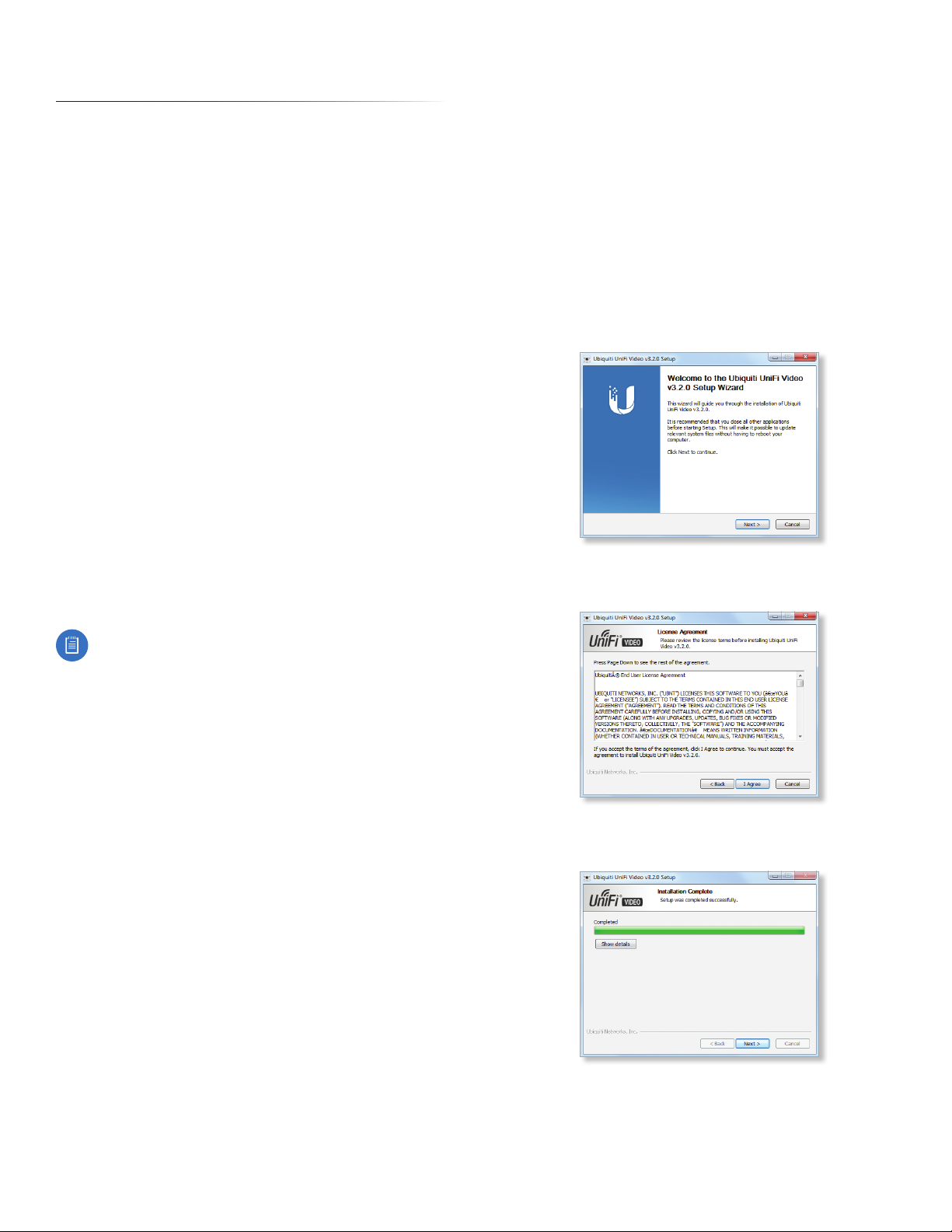
2. When the Ubiquiti UniFi Video Setup wizard starts, click
Next to continue the installation.
3. Click I Agree to accept the license agreement and
continue with setup wizard.
Note: UniFi Video v3.2 does not support airCam
cameras.
System Requirements
• 64‑bit Debian 7.0 (or above), Ubuntu v12.04 or v14.04,
or Microsoft Windows 8/7 system with an Intel or
compatible 1.86 GHz (or above) processor with a
minimum of 2GB RAM
• Mobile: iOS or Android
• Java Runtime Environment 1.6+
• Web Browser: Google Chrome
Hardware Installation
Ensure that each camera on your network is running the
latest version of the firmware. The latest firmware (and
other UniFi Video downloads) can be found online at:
www.ubnt.com/download
Follow the directions in the Quick Start Guide that
accompanied your UniFi Video Camera to install your
cameras.
4. The UniFi Video Setup wizard will install files on your
system. When it is finished, click Next.
Ubiquiti Networks, Inc.
1
Page 6
Chapter 1: Installation UniFi Video User Guide
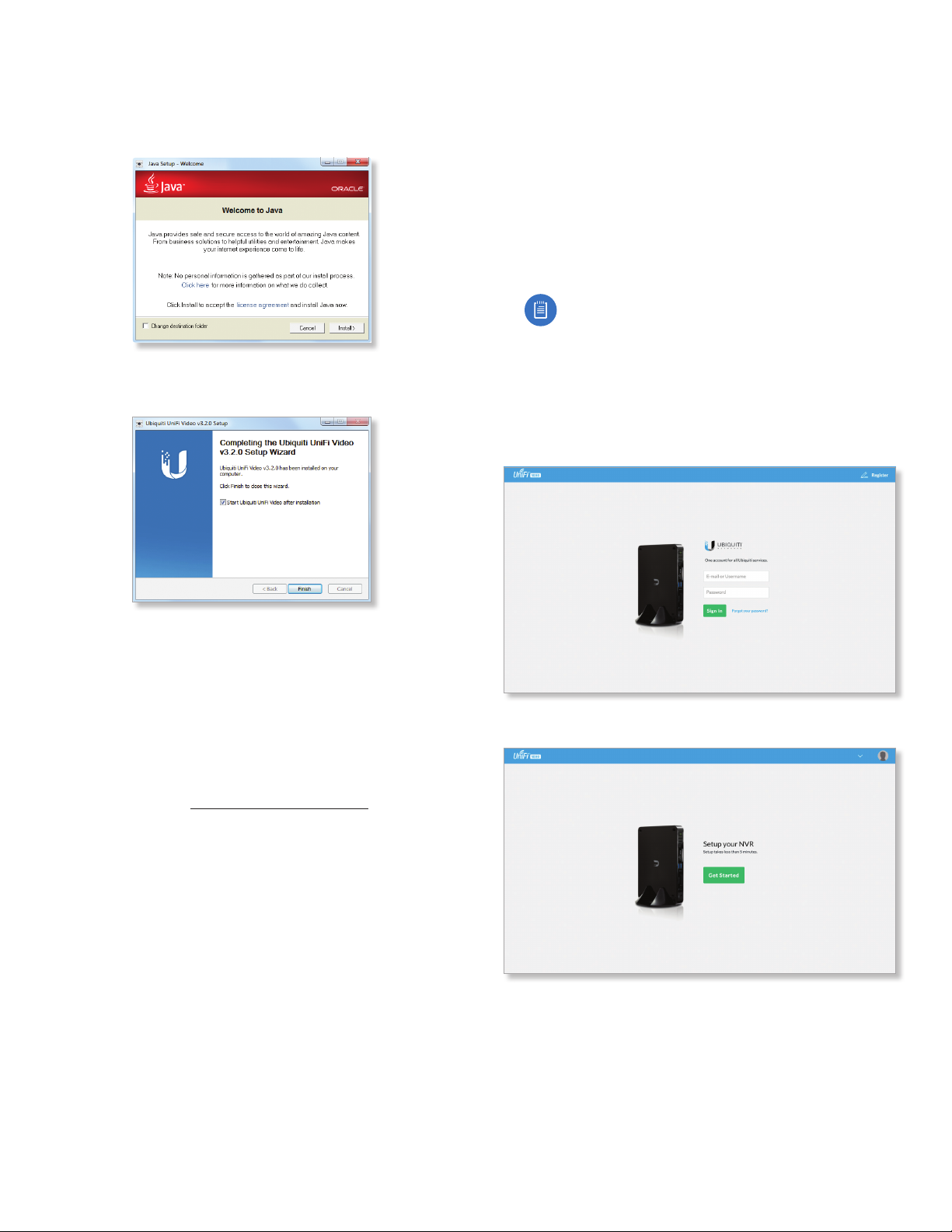
5. If your computer doesn’t have the Java 1.6 software
platform (or newer) installed, you will be prompted to
install it. Click Install to continue. Click Close when it is
finished installing.
6. Ensure that Start UniFi Video after installation is selected
and click Finish. This will start the UniFi Video service.
UniFi Video Setup
Follow these instructions to set up the UniFi Video
software for cloud access:
1. Open the Chrome browser application on any
computer on the same network as the installed
software.
2. Enter https://video.ubnt.com in your browser’s
address field. Press Enter (PC) or Return (Mac).
3. Enter the Username and Password for your Ubiquiti
account. Click Sign In.
Note: If you do not have a Ubiquiti account,
create one as follows:
1. Click Register.
2. Enter the requested information. Click
Register.
3. A verification e‑mail will be sent to the e‑mail
account you specified. Open the e‑mail and
click the link to verify your account.
Linux Installation
To install the software on linux, enter the following:
sudo dpkg -i <installation_file>
where installation_file is the file you downloaded
from www.ubnt.com/download
Mobile Installation
For detailed information on installing and using the
mobile app, refer to “Mobile App” on page 35.
4. Click Get Started to begin setup of your NVR.
2
Ubiquiti Networks, Inc.
Page 7
Chapter 1: InstallationUniFi Video User Guide
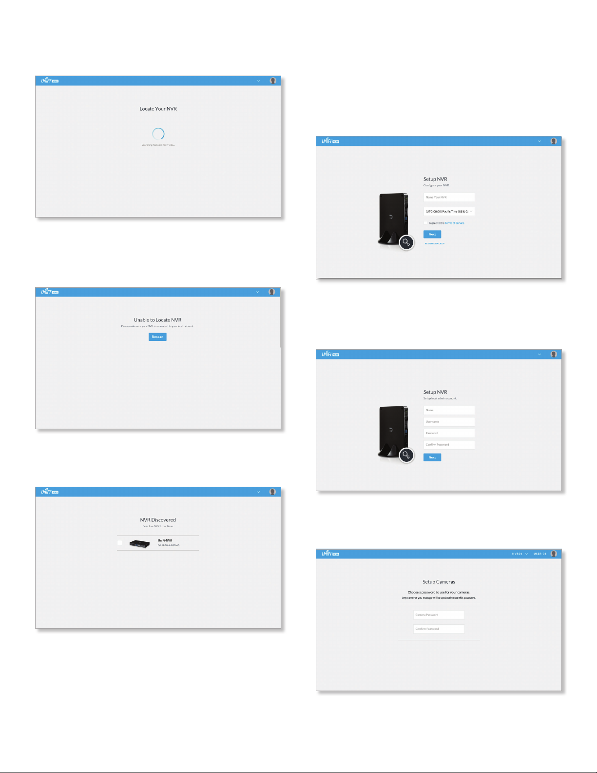
5. The setup wizard will search for the NVR on your
network.
6. If your NVR cannot be found, the wizard displays
“Unable to Locate NVR”. Verify that the NVR is
connected to your network and click Rescan to try
again.
8. The Setup NVR window will appear:
a. Enter a name for the NVR.
b. Specify your time zone.
c. Select I agree to the Terms of Service (click Terms
of Service to view the Terms of Service).
d. Click Next.
9. Create the local admin account by entering a Name,
Username, and Password (enter twice to confirm). This
information will be used to log in and access the UniFi
Video Controller system. Click Next.
7. The NVR Discovered window will appear, listing any
NVRs that were discovered. Select your NVR and click
Continue.
10. The Setup Cameras window will appear. Enter a
password (twice to confirm) to be used to manage your
cameras.
Ubiquiti Networks, Inc.
3
Page 8
Chapter 1: Installation UniFi Video User Guide
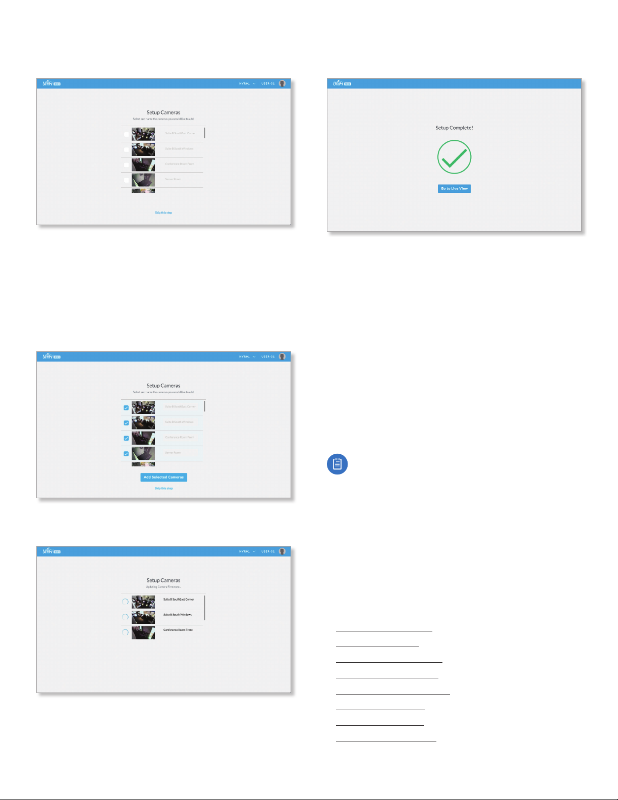
11. A list of cameras will be displayed, allowing you to
select the cameras to be controlled by the NVR.
12. If you do not want to add cameras at this time:
a. Click Skip this Step.
b. Go to step 16.
13. To add the camera(s):
a. Select each camera you want to add by clicking the
check box next to it in the list.
b. Click Add Selected Cameras.
15. When the firmware update is complete, “Setup
Complete” will be displayed. Click Go to Live View:
16. The UniFi Video Management software opens. If
you added cameras, the Live View page is displayed;
otherwise, the Cameras page is displayed.
Setup is complete.
Launching UniFi Video
After you have set up UniFi Video on your NVR, launch
UniFi Video from the cloud as follows:
1. Open the Chrome browser application on a computer
with an Internet connection.
2. Enter https://video.ubnt.com in your browser’s
address field. Press Enter (PC) or Return (Mac).
3. Enter the Username and Password for your Ubiquiti
account. Click Sign In.
4. UniFi Video will connect to your NVR and open.
14. Wait while the firmware for the selected camera(s) is
updated.
Note: You can also launch UniFi Video from a
computer on the same network as the NVR:
1. Open the Chrome browser application on a
computer on the same network as the NVR.
2. Enter https://<NVR_address> in your browser’s
address field, where NVR_address is the NVR’s IP
address. Press Enter (PC) or Return (Mac).
3. Enter the Username and Password for your admin
account on the NVR. Click Sign In.
4. The UniFi Video application will open.
Proceed to the appropriate chapter for information on
using the UniFi Video Management software:
• “Cameras” on page 9
• “Map” on page 15
• “Live View” on page 17
• “Timeline” on page 19
• “Recordings” on page 23
• “Alerts” on page 25
• “Users” on page 27
• “Settings” on page 31
4
Ubiquiti Networks, Inc.
Page 9
Chapter 1: InstallationUniFi Video User Guide
Non-Cloud UniFi Video Setup
This section describes how to launch and set up
UniFi Video using the software installed in “Software
Installation” on page 1.
Windows Launch
Launch includes two steps:
1. Start the UniFi Video service. If you selected Start UniFi
Video after installation when you installed the software,
the UniFi Video service will be started automatically.
If you didn’t select the option to start the UniFi Video
service automatically, you can start it using one of the
following two methods:
‑ Start Menu
a. Click the Start menu and select All Programs from
the popup menu.
b. Scroll down to Ubiquiti UniFi Video and click the
folder name once to expand its contents.
c. Select Ubiquiti UniFi Video. This will launch the
UniFi Video tray icon in the bottom right corner of
the Windows taskbar.
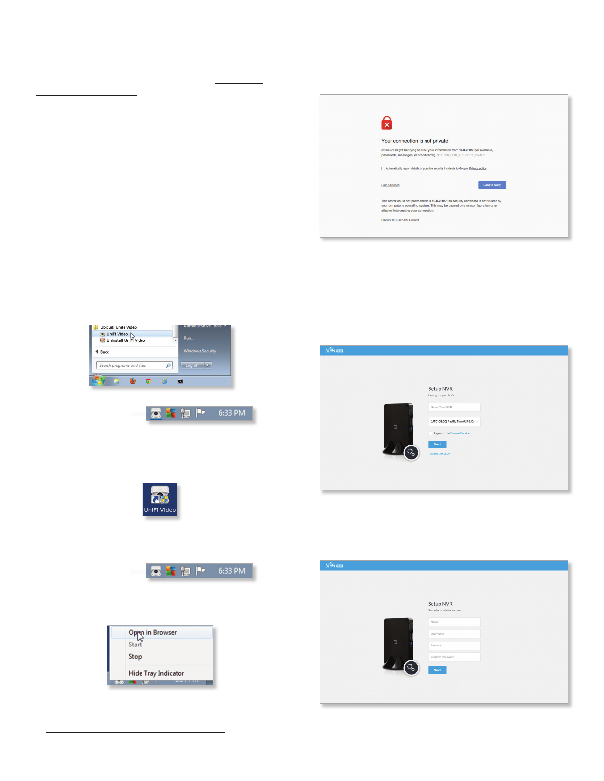
Windows UniFi Video Setup
1. If you receive a security warning, click Advanced, and
then click Proceed to <NVR IP address>.
2. The Setup NVR window will appear:
a. Enter a name for the NVR.
b. Specify your time zone.
c. Select I agree to the Terms of Service (click Terms
of Service to view the Terms of Service).
d. Click Next.
UniFi Video Tray Icon
‑ Desktop Icon
a. Double‑click the icon shown below to start the UniFi
Video service.
b. The UniFi Video tray icon will appear in the bottom
right corner of the Windows taskbar.
UniFi Video Tray Icon
2. Click the UniFi Video tray icon and select Open in
Browser from the pop‑up menu.
3. Create an Admin account by entering a Name,
Username, and Password (enter twice to confirm). This
information will be used to log in and access the UniFi
Video Controller system. Click Next.
The UniFi Video software will open in your browser. The
first time you use the software, set up the NVR as detailed
in “Windows UniFi Video Setup” on page 5.
Ubiquiti Networks, Inc.
5
Page 10
Chapter 1: Installation UniFi Video User Guide
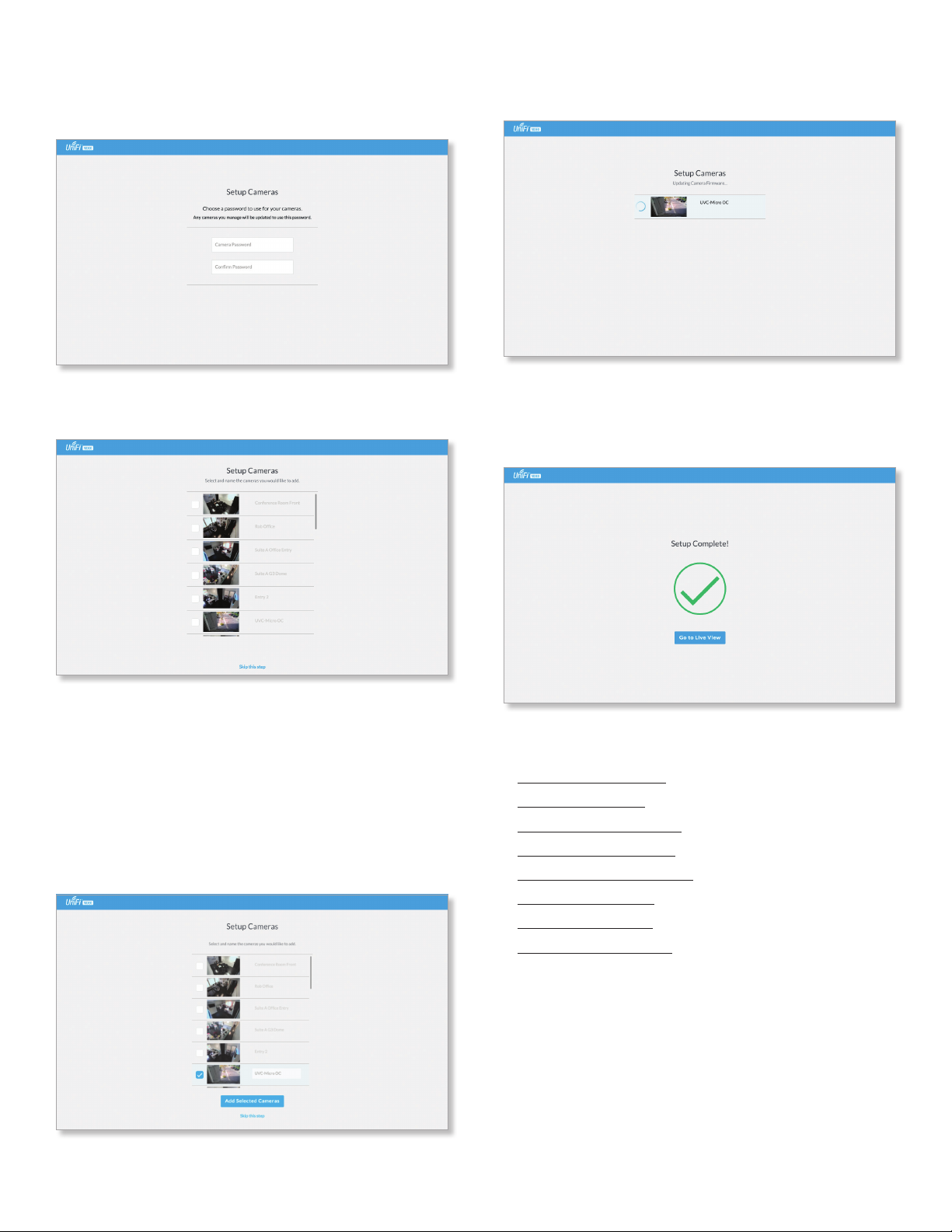
4. The Setup Cameras window will appear. Enter a
password (twice to confirm) to be used to manage your
cameras.
5. A list of cameras will be displayed, allowing you to
select the cameras to be controlled by the NVR.
8. Wait while the firmware for the selected camera(s) is
updated.
9. When the firmware update is complete, “Setup
Complete” is displayed. Click Go to Live View to display
the cameras on the Live View page of the UniFi Video
Management software:
6. If you do not want to add cameras at this time:
a. Click Skip this Step.
b. The UniFi Video Management software opens and
displays the Cameras page.
c. Setup is complete.
7. To add the camera(s), select them as follows:
a. Click the check box next to the camera in the list.
b. Click Add Selected Cameras.
Proceed to the appropriate chapter for information on
using the UniFi Video Management software:
• “Cameras” on page 9
• “Map” on page 15
• “Live View” on page 17
• “Timeline” on page 19
• “Recordings” on page 23
• “Alerts” on page 25
• “Users” on page 27
• “Settings” on page 31
6
Ubiquiti Networks, Inc.
Page 11

Enabling Cloud Access from Existing Installations
If you have upgraded to UniFi Video version 3.2 from an
older version, follow these instructions to enable cloud
access to your UniFi Video Management system:
1. Launch the UniFi Video Management software, as
described in “Launching UniFi Video” on page 4.
2. Click Settings to open the Settings page.
3. Click Connect to My Ubiquiti Account.
Note: If you do not have a Ubiquiti account, you
must create one before continuing. Create a new
Ubiquiti account as follows:
1. Go to https://video.ubnt.com
2. Click Register.
3. Enter the requested information. Click
Register.
4. A verification e‑mail will be sent to the e‑mail
account you specified in the previous step.
Open the e‑mail and click the link to verify your
account.
5. Enter your Username and Password of your Ubiquiti
account to connect the account to the NVR.
6. You will now be able to access your UniFi Video
Management system from https://video.ubnt.com
Chapter 1: InstallationUniFi Video User Guide
Ubiquiti Networks, Inc.
7
Page 12

UniFi Video User Guide
8
Ubiquiti Networks, Inc.
Page 13
Chapter 2: CamerasUniFi Video User Guide
Chapter 2: Cameras
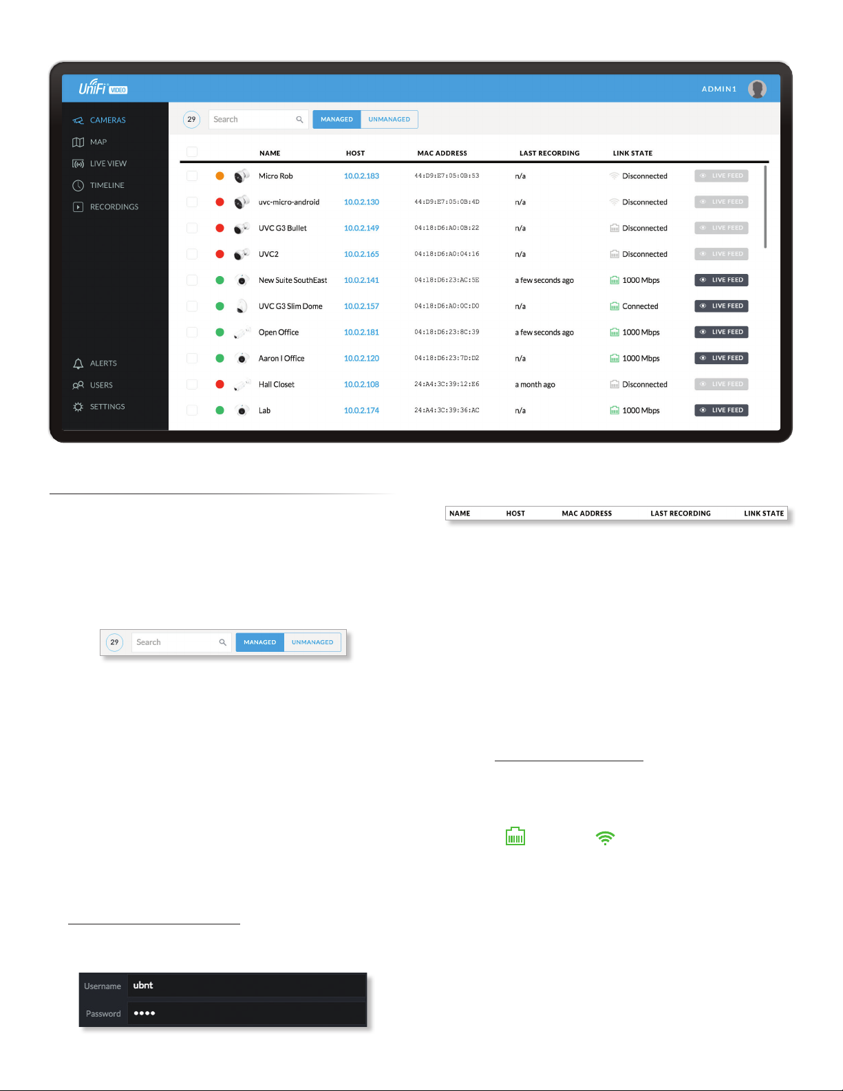
On the Cameras page, you have the option to view all
cameras (default), a selected group of cameras, or a single
camera, depending on your search criteria. The Search
option will narrow down the list of cameras displayed as
you type characters into the Search text field, eliminating
the ones that don’t match your search criteria. The
searchable columns are Name, Host, and MAC Address.
Each camera will be categorized as Managed or
Unmanaged and the number in the upper left corner
indicates how many cameras you have per category. In
this example, there are 29 Managed cameras.
Cameras listed under the Managed tab have been added
to the UniFi Video management system. Cameras listed
under the Unmanaged tab have not been configured or
added to the UniFi Video management system yet, or have
been unmanaged.
To change the status of a camera from Unmanaged to
Managed, follow these steps:
1. Click Unmanaged to see a list of unmanaged cameras.
2. Click a camera to view its details. Refer to
“Configuration” on page 14.
3. Enter the username and password for the selected
camera and click Manage.
Once you’ve finished adding the unmanaged cameras,
click Managed to return to the Managed cameras view.
For each camera, the Managed camera view lists the Name,
Host (address), MAC Address, Last Recording, and Link State.
Click a column heading to sort the list by that column;
click again to reverse the sort order.
Name Displays the local device name and a thumbnail
image of the camera.
Host Displays the local host IP address assigned to each
specific camera.
MAC Address Displays the MAC Address of the camera.
Each camera has its own unique hardware address.
Last Recording Displays how long it has been since a
camera recorded something based on its recording mode.
Refer to “Recording” on page 12.
Link State Displays the following information for the
currently selected camera:
• Connection type:
• Wired or Wireless
Green icon: Camera is connected
Gray icon: Camera is disconnected
• Connection state: Connected, Disconnected, Rebooting,
Unauthenticated
• Connection speed in Mbps (wired cameras only)
• Connection quality in dBm (wireless cameras only)
Ubiquiti Networks, Inc.
9
Page 14
Chapter 2: Cameras UniFi Video User Guide
Live Feed Click
selected camera.
LIVE FEED
to view a live feed of the
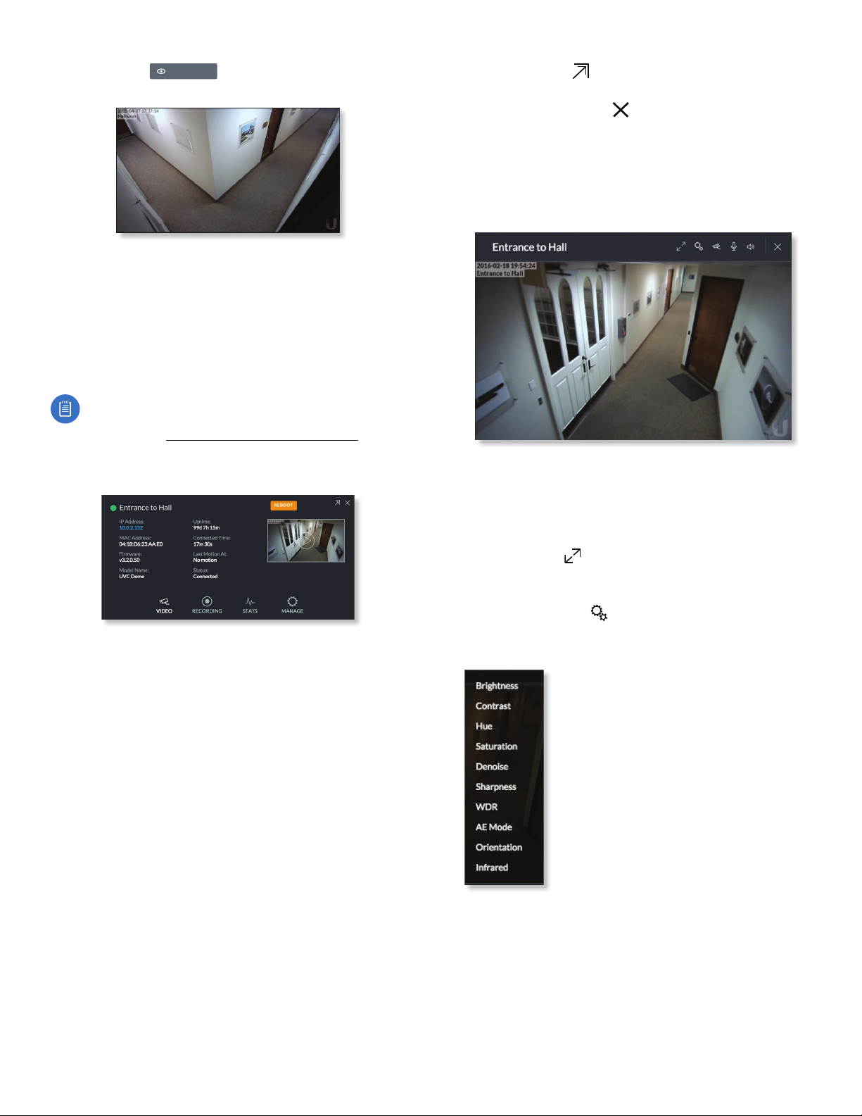
Camera Details Window
Click a camera to view the details window and display its
IP Address, MAC Address, Model Name, Uptime, Connected
Time, Last Motion At, and Status. To select more than one
camera, click the checkbox next to each camera. To select
a range of cameras, press and hold Shift, and then click the
first and last cameras in the range.
Note: To select a camera, do not click the Host
column (doing so brings up the camera’s web UI,
described in “Camera Window” on page 10).
The Camera Details window also has four clickable tabs:
Video, Recording, Stats, and Manage.
Hide Details Click to hide the camera details. Click it
again to reveal the camera details.
Exit Camera Detail Click to close and exit the Camera
Details window.
Live Stream Click the image thumbnail in the upper-right
corner to display the live stream window of the selected
camera.
Live Stream Window
The Live Stream window above has a menu bar in the
upper right corner that allows you to view the camera
feed in Full Screen, adjust the Image Settings, change the
Camera Resolution, and adjust the volume controls for
audio input and output.
Full Screen Click to view the live stream window in
full screen. Press esc on your keyboard to exit full screen
mode and return to the window view.
IP Address Displays the local IP address of the camera.
MAC Address Displays the MAC (Media Access Control)
Address of the camera. Each camera has its own unique
hardware address.
Firmware Displays the version of the firmware currently
installed on the camera.
Model Name Displays the model name of the camera.
Uptime Displays the amount of time that a camera has
been running without interruption or since last reboot.
Connected Time Displays the amount of the time the
camera has been connected.
Last Motion At Displays the last date and time that
motion was detected by the camera you are currently
viewing.
Status Displays the current status of the camera.
Indicators are Connected, Disconnected, or Rebooting.
Reboot (Functional for administrators only.) Click
Reboot to reboot the camera. The camera’s status
will temporarily change from Connected to Rebooting,
and then Disconnected before coming back online as
Connected. Rebooting a camera will also reset the Uptime
and Connected Time fields in the details window.
Image Settings Click to view the imaging drop-down
menu that allows you to change the live view image
settings for each of the following:
• Brightness Adjust the brightness of
the live view image by dragging the
slider control to the left or right.
• Contrast Adjust the contrast of the
live view image by dragging the slider
control to the left or right.
• Hue Adjust the hue of the live view
image by dragging the slider control
to the left or right.
• Saturation Adjust the saturation of
the live view image by dragging the
slider control to the left or right.
• Denoise Adjust the noise level of the live view image
by dragging the slider control to the left or right.
• Sharpness Adjust the sharpness of the live view image
by dragging the slider control to the left or right.
• WDR Adjust the WDR (Wide Dynamic Range) sensitivity
of the live view image by dragging the slider control
to the left or right. WDR helps create better image and
video detail in frames that contain both light and dark
areas that would otherwise be over- or underexposed.
10
Ubiquiti Networks, Inc.
Page 15
Chapter 2: CamerasUniFi Video User Guide
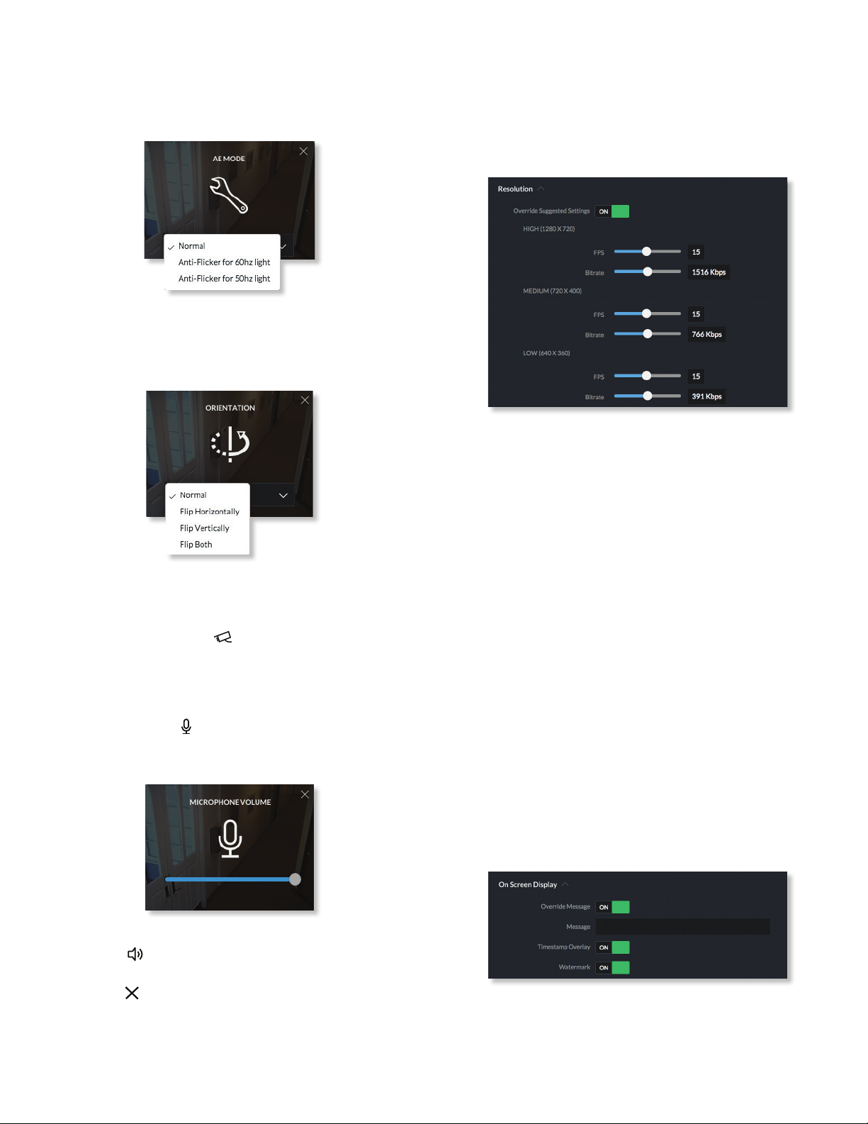
• AE Mode Choose AE (Auto Exposure) mode for the
live view images by selecting Normal, Anti-Flicker for
60Hz light, or Anti‑Flicker for 50 Hz light from the
drop-down menu. The default is Normal.
• Orientation Change the way an image is displayed
in the live stream window by selecting Normal, Flip
Horizontally, Flip Vertically, or Flip Both from the
drop-down menu. The default setting is Normal.
• Infrared The infrared filter can be changed for the live
view image by selecting On or Off from the drop-down
menu. The default setting is Auto.
Camera Resolution Click to set the live view image
resolution to High, Medium, or Low. The default setting
is Auto, which allows the camera to choose the best
supported setting automatically.
Microphone Volume (Option available for cameras that
support audio.) Click to adjust the microphone volume
used to record audio input for a recording. You can adjust
the volume by dragging the slider horizontally.
Video
Resolution
Resolution in this section refers to video output quality
expressed in total pixels: image length (horizontal) x
image height (vertical).
Override Suggested Settings Click to enable or disable
manual override of the selected camera’s resolution
settings. With Override Suggested Settings set to ON, you
will be able to adjust FPS (frames per second, also known
as frequency) and Bitrate for each resolution’s video
output.
High
FPS Drag the slider to choose a frame rate for the selected
camera’s video output resolution.
Bitrate Drag the slider to choose a bitrate for the selected
camera’s video output resolution.
Medium
FPS Drag the slider to choose a frame rate for the selected
camera’s video output resolution.
Bitrate Drag the slider to choose a bitrate for the selected
camera’s video output resolution.
Low
FPS Drag the slider to choose a frame rate for the selected
camera’s video output resolution.
Bitrate Drag the slider to choose a bitrate for the selected
camera’s video output resolution.
Audio Output (Option available for cameras that support
audio.) Click to mute or unmute the live view audio
feed of the camera.
Close Click to close the Camera Details window and
exit back to the home screen.
Ubiquiti Networks, Inc.
On Screen Display
Override Message Click to enable or disable message
override. When enabled, enter the text, for example, Rob’s
Office, that you want to be displayed on the video feed for
the selected camera.
11
Page 16
Chapter 2: Cameras UniFi Video User Guide
Timestamp Overlay Click to enable or disable the
timestamp from appearing on the live video feed.
Watermark Click to enable or disable the visibility of the
watermark on the live video feed of the selected camera.
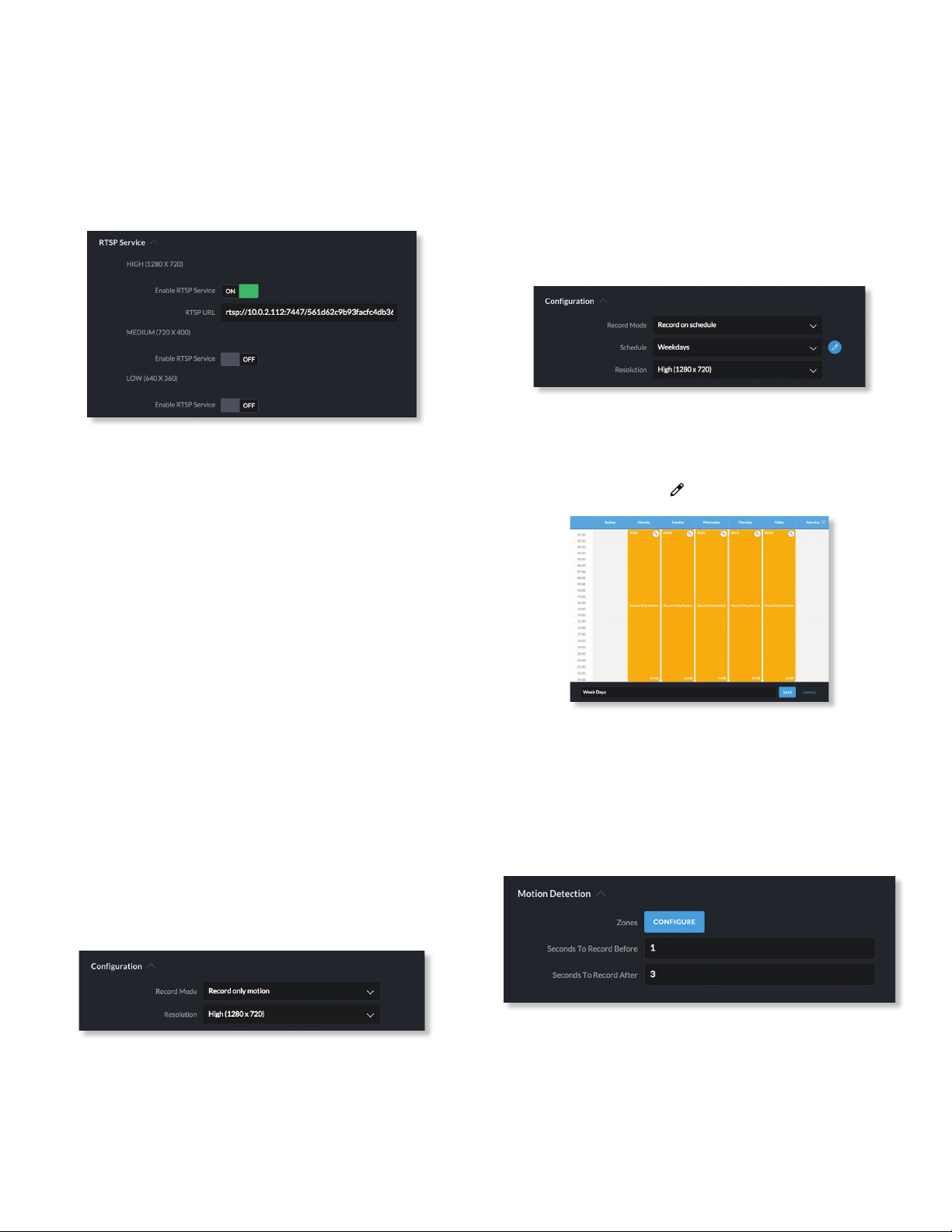
RTSP Service
RTSP (Real Time Streaming Protocol) is a network protocol
designed for facilitating the playback of media files.
High
Enable RTSP Service Click to enable the RTSP Service and
display the RTSP URL for the selected camera. The default
setting is OFF.
• RTSP URL URL link to a camera’s live video stream. You
can copy and paste this address into your web browser
for live viewing.
Medium
Enable RTSP Service Click to enable the RTSP Service and
display the RTSP URL for the selected camera. The default
setting is OFF.
• RTSP URL URL link to a camera’s live video stream. You
can copy and paste this address into your web browser
for live viewing.
Low
Enable RTSP Service Click to enable the RTSP Service and
display the RTSP URL for the selected camera. The default
setting is OFF.
• RTSP URL URL link to a camera’s live video stream. You
can copy and paste this address into your web browser
for live viewing.
• Don’t record Nothing will be recorded by the camera.
• Always record Enables the camera to record all the
time, regardless if there is motion detected or not.
• Record only motion All captured images are analyzed
and only recorded when motion is detected.
• Record on schedule Allows you to set up a specific
recording schedule for each individual camera.
Choosing this Record Mode will display a Schedule
option. Click the Schedule drop-down menu to create a
new schedule or select from a list of existing schedules.
- New Schedule To create a new recording schedule,
click and drag a block of time on each day you would
like the camera to record. When you are finished,
click Save. You can also update or delete an existing
schedule by clicking to view it in edit mode.
Resolution Choose one of the following three resolutions
to use for the selected camera:
High High resolution
•
Medium Medium resolution
•
Low Low resolution
•
Motion Detection
Recording
Configuration
Record Mode Allows you to define the recording mode of
the selected camera.
• Don’t change This option only appears when multiple
cameras are selected. Choosing this option keeps the
cameras in their current recording mode.
12
Zones Click Configure to edit motion zones for the
selected camera. This option does not appear if multiple
cameras are selected, as zones are configured individually.
Minimum Motion Event Trigger Drag the slider control
left or right to set the minimum duration (0 to 5 seconds)
that motion must take place to trigger recording.
Ubiquiti Networks, Inc.
Page 17
Chapter 2: CamerasUniFi Video User Guide
Seconds To Record Before Enter the number of seconds
you want UniFi Video to record before the triggering
motion occurs on the selected camera.
Seconds To Record After Enter the number of seconds
you want UniFi Video to record after the triggering motion
occurs on the selected camera.
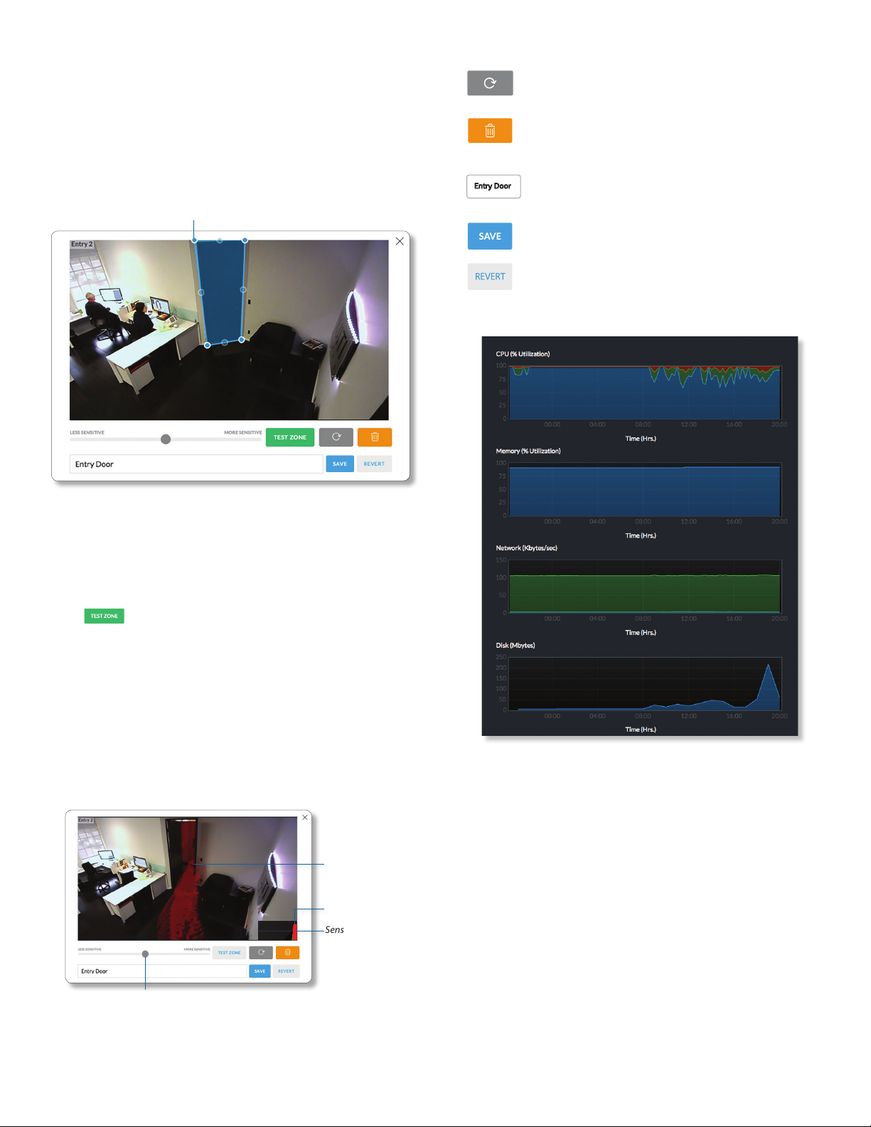
Configuring a Zone
Adjustment Points
Click to refresh the camera image that
appears in the zone preview.
Use this button to delete the current zone.
Click an area of the camera feed to define
another zone after deleting the existing zone.
Enter a name or brief description of the zone
Entry Door
you are creating, in the text field provided. In
this example, Entry Door is used.
Click Save when you are done configuring
and naming your new zone.
Click Revert to cancel all changes and restore
the previous settings.
Stats
By default, the initial zone for each camera is the entire
viewing area captured in the live feed window. Click
and drag the Adjustment Points from each corner of the
window to the perimeter of the area you would like to
define as your zone. Only motion within this zone will
trigger recording.
Click to test the zone you just created and adjust
the sensitivity using the Sensitivity Slider control. Image
trails will appear when motion is detected and the
sensitivity level and motion spikes will appear in the
bottom right corner of the camera feed. The sensitivity
level is represented by the blue line. As various degrees of
motion occur, you’ll see spikes of different levels. Adjust
the sensitivity to a level that best suits your needs. Motion
spikes that exceed the defined sensitivity threshold will
be recorded when motion recording is enabled. Click Test
Zone again to stop the test.
Motion Trails
Motion Spike
Sensitivity Level
Sensitivity Slider
CPU (% Utilization) Displays the camera’s CPU utilization
recorded over 24 hours with high, low, and average points
highlighted. Red indicates the highest point, green is the
average, and blue is the lowest point during sampled
intervals.
Memory (% Utilization) Displays the percentage of the
camera’s memory utilization over a 24-hour period.
Network (Kbytes/sec) Displays the network traffic for the
selected camera over the last 24 hours. Graph is expressed
in kilobytes per second.
Disk (Mbytes) Displays the amount of disk usage for the
selected camera over the last 24 hours. Graph is expressed
in total megabytes.
Ubiquiti Networks, Inc.
13
Page 18
Chapter 2: Cameras UniFi Video User Guide
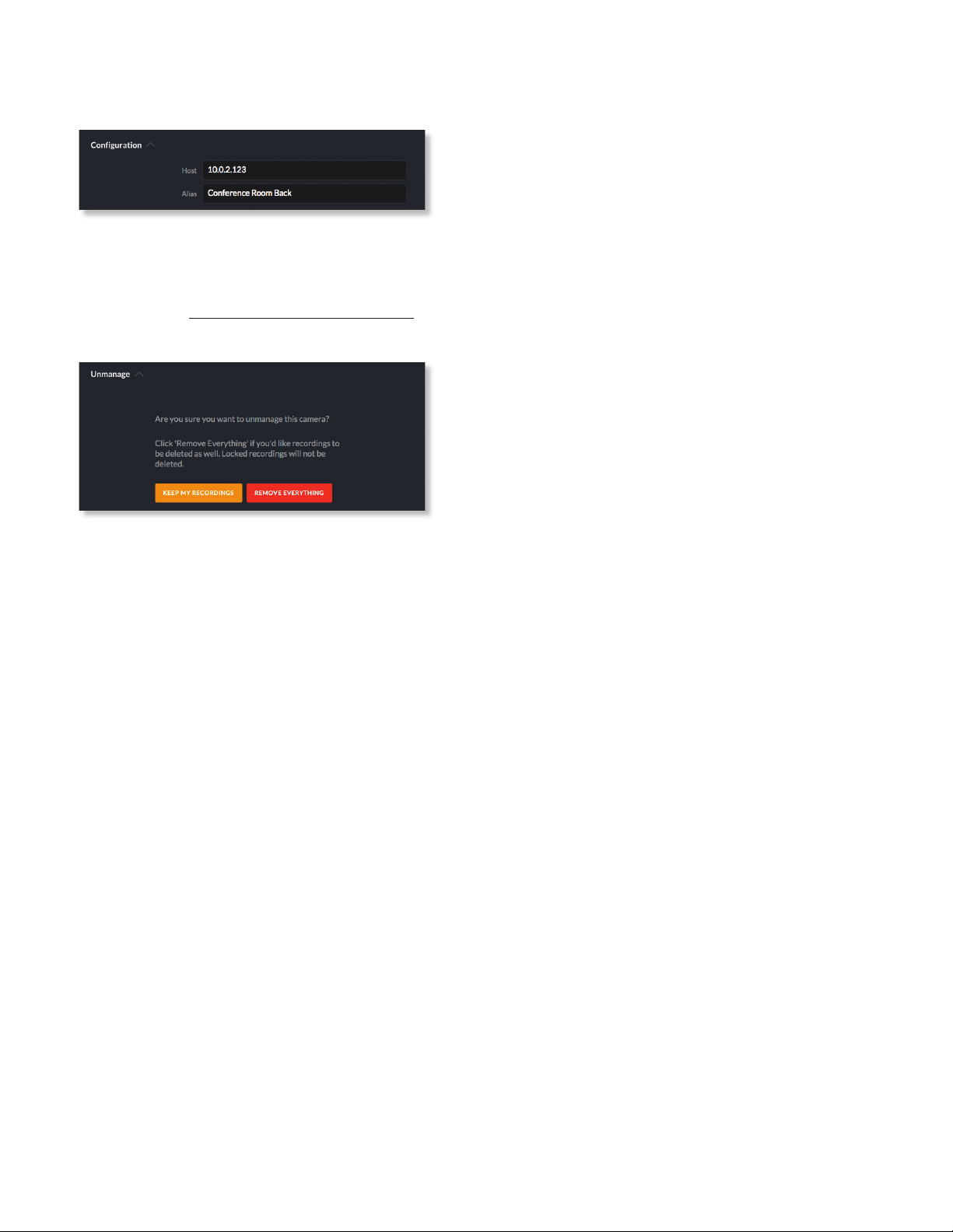
Manage
Configuration
Host Displays the local IP address configured for the
camera you are currently viewing.
Alias Displays the device name configured for the live
feed window for each camera. This is different from the
name described for “On Screen Display” on page 11.
Unmanage
Click Unmanage if you no longer want to manage the
selected camera. In doing so, you will have the following
options:
Keep My Recordings Click Keep My Recordings to
remove the camera from your management system, but
retain all existing recordings made by the camera.
Remove Everything Click Remove Everything to remove
the camera and delete all recordings (except locked
recordings) made by the camera.
14
Ubiquiti Networks, Inc.
Page 19

Chapter 3: MapUniFi Video User Guide
Chapter 3: Map
The Map page allows you to upload custom map images
of your site or floor plan, including aerial locations from
Google Maps™ for a visual representation of your camera
layout.
The map also indicates if motion has been detected on
a camera. The color of each camera’s field of view varies
from red (motion currently detected) to green (no recent
motion).
Defining a Map
You can add an image you’ve created as a map image
or use Google Maps to generate an image for use as a
background.
Image Map
To add a custom map, you must first create the image
using an illustration, image editing, or blueprint
application that exports .jpg, .gif, or .png file formats.
Once you’ve created the map, you can upload it to the
UniFi Video software by performing the following steps:
1. Click Add New Map in the Map drop‑down menu.
2. Enter a map name in the Enter new map name field and
click Image Map.
3. Select the file to use as a map (valid file formats are
.jpg, .gif, and .png). Click Open.
4. Click Add Map.
5. Zoom in on the map using the button on the left.
Zoom out using the button.
Ubiquiti Networks, Inc.
15
Page 20

Chapter 3: Map UniFi Video User Guide
6. Click the button in the upper right corner to bring
up a list of cameras for placement. Drag the camera
from the Cameras list on the right to the appropriate
location on the map. The camera will appear in the area
it was placed.
Camera Placement
Camera thumbnails can be placed on the map to show the
location of your cameras. To reposition a camera on the
map, click and hold the Camera thumbnail and then drag
the camera to another location on the map.
Google Map
To create a custom map using Google Maps, perform the
following steps:
1. Click Add New Map in the Map drop‑down menu.
2. Enter the desired address in the Enter location field and
click Locate.
3. Enter a map name in the Enter new map name field and
click Add Map.
4. Zoom in on the map using the button on the left.
Zoom out using the button.
5. Click the button in the top right corner to bring
up a list of cameras for placement. Drag the camera
from the Cameras list on the right to the appropriate
location on the map. The camera will appear in the area
it was placed.
Click and drag the black dot to adjust the camera’s
direction and field of view.
Click the Camera icon to reveal additional options:
LiveFeed , Details , and Remove .
Live Feed
Click the Live Feed icon to bring up the camera’s Live
Stream window. The details are described in “Live Stream
Window” on page 10.
Details
Click the Camera Details icon to bring up the Camera
Details page. The details are described in “Cameras” on
page 9.
Delete
Click the icon to remove the camera from the map.
16
Ubiquiti Networks, Inc.
Page 21

Chapter 4: Live ViewUniFi Video User Guide
Chapter 4: Live View
You can monitor multiple camera feeds through a
single view layout using the Live View page. There are 12
pre‑defined templates that support up to 26 cameras. Live
View allows you to select which camera layout to use and
which video feeds to display in that particular layout.
Create a New View
To create a custom Live View, follow these steps:
1. Click the drop‑down box at the top left of the window.
Click New View.
2. Select a layout by clicking one of the templates in the
Choose a Layout window.
3. Do the following for each of your cameras:
a. Click the Camera Select icon in the bottom right
corner of a video feed area to display the list of
available cameras.
b. Assign the camera to the video feed area using one
of the following methods:
• Select a camera from the list.
• Search for a camera name (or part of a name) by
entering it into the Search field at the top of the list.
• Select Advanced at the bottom of the list to open
the Advanced dialog. Then select the camera from
the drop‑down list and select the Cycle On setting:
Motion or Time Interval.
4. The cameras will appear in the areas of the layout
and you will see their live video feeds in the Live View
window.
Ubiquiti Networks, Inc.
17
Page 22

Chapter 4: Live View UniFi Video User Guide
5. To view or modify the details of any camera in your
layout, click the Configure icon and refer to “Camera
Details Window” on page 10.
6. Save the layout by entering a name or brief description
in the View Name text field and clicking Save on the
right side of the menu bar. Or, click Delete to delete the
view without saving it.
Edit a View
To edit an existing Live View, follow these steps:
1. Display the view that you want to edit by selecting it
from the drop‑down list. Then click Edit View.
2. Edit the view using the icons displayed in the video
feeds of the layout:
‑ Camera Select Click this icon to assign a different
camera to the video feed.
‑ Configure Click this icon to display the camera
details window (described in detail in “Camera
Details Window” on page 10).
‑ Camera Resolution Click this icon to set the
camera’s resolution to one of the following settings:
Auto (Medium), High, Medium, Low.
‑ Audio Click this icon to mute or unmute the audio.
3. Save the edited layout by clicking Save on the right
side of the menu bar. Click Revert to cancel the
changes you’ve made to the view.
2. Click Edit View next to the camera layout you selected
and enter a new name for the layout.
3. Click Save to save the changes you’ve made to the
view. Click Revert to cancel the changes you’ve made
to the view.
Deleting a View
You can delete an existing view or layout by performing
the following steps:
1. Click the drop‑down list of existing camera layouts and
select the view you want to delete.
2. Click the Delete button to remove a view.
3. When prompted, click Delete to confirm.
Renaming a View
You can rename an existing view or layout by performing
the following steps:
1. Click the drop‑down list of existing camera layouts and
select the view you want to rename. In this example,
we will use Front Office.
18
Ubiquiti Networks, Inc.
Page 23

Chapter 5: TimelineUniFi Video User Guide
Chapter 5: Timeline
The Timeline page allows you to selectively view the parts
of recorded video clips where motion has been detected.
You can also set the duration of video to play, adjust the
playback speed, and move directly to any point in a clip.
Keyboard shortcuts are also provided as a convenient
method of control during playback.
Selecting a Clip for Playback
Select a clip to view involves the following steps:
1. Select the camera whose video clip(s) you want to view.
2. Select the playback date.
3. Select the playback start time and duration.
4. Select the playback rate.
Select Camera
1. At the lower left of the video screen, click the dropdown box to display a list of available cameras.
Select Playback Date
1. The playback date is displayed below the center of the
video screen.
Playback Date
2. To change the date, click it to display a calendar, and
then select the desired date.
Camera List
2. Select the desired camera.
3. If the camera has no recorded video clips, “No Video” is
displayed; select another camera for playback.
Ubiquiti Networks, Inc.
3. Click to close the calendar.
19
Page 24

Chapter 5: Timeline UniFi Video User Guide
Select Playback Start Time and Duration
1. The playback start time is displayed at the lower left
side of the video screen.
Playback Start Time
Back Forward
2. To change the start time, use the and controls
(Back and Forward, respectively) on the left and right
sides of the window. Each click will move the start time
forward or backward by half the value of the playback
duration. For example, if the duration is one hour,
clicking will move the start time back 30 minutes.
3. The playback duration is displayed at the lower right of
the video screen.
4. To change the duration, click it to display a list of
available values: 24Hrs, 12Hrs, 6Hrs, 1Hr, or 30Min.
Select the desired duration. The default is 1Hr.
Playback Duration
• Zoom When you position the cursor over the video
screen, the Zoom control appears, allowing you to zoom
in on specific parts of the video display, or to zoom back
out. Use the slider control or the and buttons to
adjust the zoom factor.
When you zoom in, a small box will appear in the upperright corner of the video display, showing the zoomedin area within the main field of view. To zoom in on a
different area, click and drag the video screen until the
desired area is displayed.
Control buttons used for playback include the following:
Select Playback Rate
1. The playback rate is displayed below the center of the
video screen.
Playback
Rate
2. To change the rate, click it to display a list of available
rates: 0.25x, 0.5x, 1x, 2x, 4x, or 8x. Select the desired rate.
The default is 1x.
Playback
After you have selected the video clip, use the controls to
view it. The controls include:
• Timeline The Timeline shows the start and end times
of the video clip, with tick marks at regular intervals in
between. Drag the slider to advance directly to a
specific point in the video.
Play/Pause
Full-Screen
Shortcuts
• Click Play to start playing the clip. The playback
automatically plays only the sections of the clip where
motion has been detected.
• Click Pause to stop playing the clip.
• Click Full-screen to enlarge the video display to fullscreen or reduce it from full-screen back to normal size.
• Click Shortcuts to display a list of keyboard
shortcuts:
• Motion Bar The Motion Bar contains red markers to
show where motion has been detected in the video clip.
20
Ubiquiti Networks, Inc.
Page 25

Keyboard shortcuts include:
• + Zoom In – Changes the playback duration to the
next lower value (for example, from 1Hr to 30Min).
• – Zoom Out – Changes the playback duration to the
next higher value (for example, from 1Hr to 6 Hrs).
• > Increase Speed – Changes the playback rate to the
next higher value (for example, from 1x to 2x).
• < Decrease Speed – Changes the playback rate to the
next lower value (for example, from 0.5x to 1x).
• ctrl + Increase Marker Size – Increases the height of
the markers in the Motion Bar.
• ctrl – Decrease Marker Size – Decreases the height of
the markers in the Motion Bar.
• spacebar Play/Pause – Starts/stops playback.
• ▶ Next Second – Advances the video by one second.
• ◀ Previous Second – Moves the video back by one
second.
• alt ▶ Next Frame – Moves the timeline forward one
frame.
• alt ◀ Previous Frame – Moves the timeline back one
frame.
• shift ▶ Scroll Timeline Forward – Moves the Timeline
start and end times forward (later in time). This has the
same effect as the control.
• shift ◀ Scroll Timeline Backward – Moves the Timeline
start and end times backward (earlier in time). This has
the same effect as the control.
When you are finished viewing the shortcut list, click
to close the list.
Chapter 5: TimelineUniFi Video User Guide
Ubiquiti Networks, Inc.
21
Page 26

Chapter 5: Timeline UniFi Video User Guide
22
Ubiquiti Networks, Inc.
Page 27

Chapter 6: RecordingsUniFi Video User Guide
Chapter 6: Recordings
The Recordings page lets you search, sort, and view saved
video recordings based on camera name, recording
type, recording date, or length of video clip. Each of the
following column headers is a clickable label that sorts the
list of recordings alphabetically or numerically, depending
on the type of data contained in that field: Camera, Type,
Date/Time, and Length.
Camera Displays the local device name of each camera
that recorded a video clip on the Recordings page.
Type Displays the type of recording that was made based
on the recording mode defined in the camera details. The
two types are Motion and Full Time.
Date/Time Displays the date and time each video clip
was recorded.
Length Displays the length of each video clip recorded.
Date Range
Today Displays a list of all video recordings made within
the last day (24 hours).
Last Week Displays a list of all video recordings made
within the last week (7 days).
Last Month Displays a list of all video recordings made
within the last month.
From Specify the beginning range of video recordings.
To Specify the ending range of video recording.
Cameras
Select Camera Allows you to filter your search by camera
name. The Search option will narrow down the list of
cameras as you type into the Search box, eliminating the
ones that don’t match your search string criteria.
All Cameras Click All Cameras to display the video
recordings made by every camera.
Type
Motion Recordings Check this box to include
motion‑detection recordings.
Full Time Recordings Check this box to include full‑time
recordings.
Ubiquiti Networks, Inc.
23
Page 28

Chapter 6: Recordings UniFi Video User Guide
Locked
Locked Recordings Check this box if you would like
to include Locked Recordings in the list of video clips
displayed in the Recordings window.
Unlocked Recordings Check this box if you would like
to include Unlocked Recordings in the list of video clips
displayed in the Recordings window.
Viewing Recordings
Play Click the video clip to open a window where you
can view the recording. Use the controls displayed in the
window as follows:
Icon Name Function
Play Click to start playing the video clip. The icon
Pause Click to stop playing the video clip. The icon
Playback
Rate
Mute Click to mute the camera’s audio. The icon
Unmute Click to unmute the camera’s audio. The icon
Motion
Indicator
Full‑
screen
changes to the Pause icon.
changes to the Play icon.
Click to set the playback rate to one of the
following: 0.25x, 0.5x, 1x, 2x, 4x, 8x.
changes to the Unmute icon.
changes to the Mute icon.
Click to enable or disable the motion detection
indicator. When enabled, the indicator shows
where motion occurred in the field of view
using red shading.
Click to toggle the window between normal
size and full‑screen display.
Info
Click any recording to display the details and options for
the selected video clip.
Camera Displays the name of the camera.
Date/Time Displays the date and time the video clip was
recorded.
Duration Indicates the length of the video clip.
Type Displays the type of recording that was made.
Unlocked Changes the status of a video clip recording
between Locked and Unlocked. If a recording is unlocked,
the video clip can be deleted by an administrator. If a
recording is locked, the video clip cannot be deleted.
Download Click Download to save a copy of the selected
camera recording to your computer as an .mp4 video.
Delete Click Delete to initiate removal of a video clip
from the current list of recordings. A video clip can only be
deleted if it is designated as Unlocked.
Motion Detection (red-shaded areas)
24
When prompted to confirm deletion, click Delete to
permanently delete the selected recording, or click Cancel
to keep it.
Ubiquiti Networks, Inc.
Page 29

Chapter 7: AlertsUniFi Video User Guide
Chapter 7: Alerts
(The Alerts section is available to administrators only.)
Alerts and messages can be sorted by date or message
type, including software updates, camera discoveries, and
requests for management.
Alerts Home Page
Date/Time Displays the day of week, date, and time that
an event occurred.
Message Displays a description of each event recorded
by the NVR.
If you would like to remove a message from the list of
alerts, click
would like to delete.
Click any message to view specific details of the device
recorded in the selected event. Details and options will
vary based on the type of device being reported. Refer to
“Cameras” on page 9.
DELETE
next to the corresponding event you
Ubiquiti Networks, Inc.
25
Page 30

Chapter 7: Alerts UniFi Video User Guide
26
Ubiquiti Networks, Inc.
Page 31

Chapter 8: UsersUniFi Video User Guide
Chapter 8: Users
(The Users section is available to administrators only.) This
section allows you to manage user accounts on the NVR.
Name Displays the user’s full name.
Username Displays the user’s email address. This email
address is used to log into the NVR.
User Group Displays the name of the user group that
each NVR user belongs to.
User Details
Click any user account to open the Details window for that
particular user.
Full Name Displays the selected user’s full name.
Usergroup Displays the name of the user group that the
selected NVR user belongs to.
Last Logged In Displays the date and time when the
selected user account last logged in to the NVR.
Last IP Address Displays the last IP address used to log in
to the NVR (by the selected user account).
There are four clickable tabs below the user details:
Account, Password, API Access, and Delete. (Delete is not
displayed if you are viewing your own account.)
Account
Full Name View or edit the user’s full name.
E-Mail Address View or edit the user’s email address. This
email address is used to log into the NVR.
User Group Select or edit the user group for this account.
Click Edit to make changes to an existing user group. Refer
to “New User Group” on page 29 for group options.
Language Select the user’s language preference.
Local Access Used to enable or disable local access.
Ubiquiti Networks, Inc.
27
Page 32

Chapter 8: Users UniFi Video User Guide
Username The user name for the user account.
New Password Create a password for the selected user.
This password will be used to log in and access the NVR.
Confirm Password Confirm the password by entering it a
second time in the Confirm Password field.
API Access
Allow API Usage API stands for Application Programming
Interface. Click to toggle ON and display the API Key field.
Click New API Key to generate a key code when accessing
UniFi Video from external applications.
Delete
Click Delete to remove the selected user. When prompted
to confirm removal of the user, click Remove User.
Note: This option is not available when viewing your
own account.
Alerts
Alert Schedule for Motion Detection
To create a new schedule for motion detection alerts:
1. Select New Schedule in the On Motion drop-down list.
2. A window showing the days of the week and hours of
the day will be displayed.
3. Select the periods to send an alert upon motion
detection by dragging the cursor in the appropriate
days of the week.
4. Enter a name for the schedule and click Save.
To edit an existing schedule for motion detection alerts:
1. Select the schedule from the On Motion drop-down list
and click
2. The schedule will be displayed in a separate window.
3. Edit the schedule as needed.
4. When done editing, click Save to save the changes.
To delete an existing schedule for motion detection alerts:
1. Select the schedule from the On Motion drop-down list
and click
2. The schedule will be displayed in a separate window.
3. Click Delete to delete the schedule.
.
.
Receive Email Alerts Click to enable or disable email
alerts for specific cameras and events.
Camera Displays the camera name.
On Disconnect Indicates when to notify the administrator
if the selected camera becomes disconnected. Select
Never or Always.
On Motion Indicates when to notify the administrator
if the selected camera records motion. Select Never or
Always, or select New Schedule to define a schedule.
28
Ubiquiti Networks, Inc.
Page 33

Chapter 8: UsersUniFi Video User Guide
Add User
To add a new user, click Add User on the top left corner
of the window. The Create New User window will appear.
Click each tab and fill out the requested information. The
Account and Password tabs are required; the API Access tab
is optional. When you are finished, click Save.
Account
Full Name Enter the full name of the new user.
E-Mail Address Enter an email address for the new user.
This email address will be used to log in to the NVR.
User Group Click Select User Group to display the User
Group menu. Select an existing user group from the
drop-down list or select New User Group to create a new
group.
New User Group
An e-mail invitation will be sent to the new user using the
e-mail address you specified.
Upon receipt of the e-mail invitation, the new user should
click Login to accept the invitation and log into the UniFi
Video system.
If you select New User Group, the following window will
appear:
• Can receive alert notifications via email Check this
box to grant users (in this group) the ability to receive
email notifications when the NVR generates an alert
message.
• View Camera, Edit Camera, View Recording, Edit
Recordings Select which cameras and recordings
can be accessed by users in this group by clicking the
checkbox next to each camera in the list.
Ubiquiti Networks, Inc.
29
Page 34

Chapter 8: Users UniFi Video User Guide
• User Group Name Assign the group a new name by
entering it into the User Group Name field and click Save.
You can also delete the group name by clicking Delete.
Language Select the user’s language preference.
Local Access Used to enable or disable local access.
Username The user name for the user account.
New Password Create a password for the selected user.
This password will be used to log in and access the NVR.
Confirm Password Confirm the password by entering it a
second time in the Confirm Password field. Passwords must
match in both fields before UniFi Video will allow you to
save the user account.
API Access
Allow API Usage Click to enable or disable access to UniFi
Video from an external application. When enabled, click
New API Key to generate a new random key in the API Key
text field.
API Key Use this key to authenticate access to UniFi Video
from an external application.
When you are finished entering all of the information for
the new user account, click Save.
30
Ubiquiti Networks, Inc.
Page 35

Chapter 9: SettingsUniFi Video User Guide
Chapter 9: Settings
(The Settings section is available to administrators only.)
The Settings section provides you with important system
information and configuration options for your NVR.
UniFi Video Cloud
Connect To My Ubiquiti Account/Disconnect From My
Ubiquiti Account To connect your Ubiquiti account with
the NVR, click Connect to My Ubiquiti Account and enter
your credentials (the button will change to Disconnect
From My Ubiquiti Account). You will then be able to access
the NVR from video.ubnt.com using your Ubiquiti
account. To dissconnect your Ubiquiti account from the
NVR, click Disconnect From My Ubiquiti Account.
Camera Password
Camera Password Enter a new password that will be
used by all managed cameras.
Time & Date
Timezone Select the local time zone where the UniFi
Video NVR is located.
Ubiquiti Networks, Inc.
Alerts
Enable Connection Alert Emails Whenever a device is
connected or disconnected, an email alert will be sent out
if set to ON. The default setting is OFF.
Enable Motion Alert Emails When a motion event
occurs, an email will be sent out if set to ON. The default
setting is OFF.
Configure Email Alerts Click Configure Email Alerts to
customize the alert settings for each camera managed by
the NVR. To receive email alerts, click to toggle ON.
Firmware Updates
Check UBNT For Updates UniFi Video automatically
checks for system updates but doesn’t install them unless
initiated by an administrator. If you don’t want the NVR to
automatically check for updates, click to toggle OFF.
Report Statistics Statistics are gathered and provided to
Ubiquiti Networks for reference, in an effort to continually
improve performance. To opt out, click to toggle OFF.
31
Page 36

Chapter 9: Settings UniFi Video User Guide
NVR SETTINGS
Device Discovery
Discover Cameras When set to ON, your NVR will
automatically discover UniFi Video cameras as they
become available on the network. To disable this feature,
click to toggle OFF.
NVR Settings
Click
display the configuration details for the NVR.
IP Address Displays the current IP address of the NVR.
MAC Address Displays the hardware MAC address.
Version Displays the firmware version currently installed
on the NVR.
Model Name Displays the model name of the NVR.
CPU Indicates the percentage of the CPU being utilized
by the NVR.
Memory Indicates the amount of memory used by the
NVR (expressed in megabytes).
Disk Indicates the amount of disk space used on the NVR.
to open the NVR Settings window. This will
Time To Retain Defines the number of Hours, Days, or
Weeks to keep recordings before deleting them. This
option is available when Time Based Purging is set to ON.
Space to Keep Free Use the slider to define how much
space should be kept available on the NVR (expressed in
gigabytes).
Tools
Database Synchronization Allows you to analyze the
current NVR database.
Updates
Currently Installed Displays the firmware currently
installed on your NVR. If it is the most recent firmware,
“Upto Date” is also displayed.
Check for Updates Click to check the website for the
latest firmware update (requires Internet connection).
Stats
Configure
Configuration
Alias Displays the current name of the NVR.
Recording Path Path to where video clip recordings are
stored on the NVR.
Time Based Purging When enabled, recordings are
deleted after the amount of time specified in the Time To
Retain field.
CPU Displays percentage utilization of the NVR’s
processor over a 24-hour period.
Memory Displays percentage utilization of the NVR’s
memory over a 24-hour period.
32
Ubiquiti Networks, Inc.
Page 37

Network Displays the amount of network activity over a
24-hour period (expressed in kilobytes).
Disk Displays the amount of disk activity over a 24-hour
period (expressed in megabytes).
Logs
The Logs tab provides you with four separate log files
generated by the NVR in the UniFi Video management
system. Click Logs to display the current log activity. The
default log is the Error log.
Chapter 9: SettingsUniFi Video User Guide
Error Displays a running log of all error messages.
Purge Displays a running log of all purge activity.
Recording Displays a running log of all recording activity.
Connection Displays a log of all connection activity,
including loss of connection.
You can also delete, download, or refresh the view of any
log activity by clicking one of the toolbar icons located in
the upper right corner of the Logs screen.
Delete Clears the log file currently displayed on your
screen, without saving a copy to your computer.
Download Allows you to save a log file to your
computer.
Refresh Updates the running log activity on your
screen.
Ubiquiti Networks, Inc.
33
Page 38

Chapter 9: Settings UniFi Video User Guide
34
Ubiquiti Networks, Inc.
Page 39

Appendix A: Mobile AppUniFi Video User Guide
Appendix A: Mobile App
UniFi Video is now accessible from iOS and Android™
smartphones and tablets using the UniFi Video mobile
app. This appendix describes how to use the app on your
mobile device to communicate with an NVR over the
internet (cloud access).
UniFi Video App for iOS
1. If you have not connected your Ubiquiti account to the
NVR, do so now as described in “UniFi Video Cloud”
on page 31.
2. Using your smartphone or tablet, download the free
mobile app from the iTunes® App Store for iOS users.
3. Open the UniFi Video mobile app. The sign-in screen
will appear.
4. Tap Sign In. The Select NVR screen will appear.
5. At the bottom of the screen, tap Connect with your
Ubiquiti Account. A sign-in screen will appear.
Ubiquiti Networks, Inc.
35
Page 40

Appendix A: Mobile App UniFi Video User Guide
Multi-View
6. Enter your Ubiquiti account username and password
and tap SignIn.
Note: If you do not have a Ubiquiti account yet,
tap Create One, enter all requested info, and tap
Register. Then connect the account to your NVR
as described in “UniFi Video Cloud” on page
31 before continuing.
7. The Select NVR screen appears again. Select the desired
NVR from the list.
8. The app opens. By default, the Cameras screen appears:
The menu bar at the bottom of the screen has icons used
to navigate between the main screens:
• Tap to display the Cameras screen (already selected
by default).
• Tap to display the Recordings screen.
• Tap to display the Settings screen.
Cameras Screen
The Cameras screen displays a list of cameras that are
known to the UniFi controller. For each camera in the list,
the following information is displayed:
• A thumbnail image of the camera’s view (image is faded
if the camera is offline.)
• The name of the camera.
• Date and time of two different events, depending on
the connection status:
• Connected: The date and time of the last recording, or
N/A if no recordings are available.
• Not connected: The date and time when the camera
was last seen by the UniFi Video controller.
• The camera’s connection status: Connected or
Disconnected.
On the Camera screen, you have the following options:
• Select a camera from the list to open the Camera Detail
screen which contains a live video feed from the camera
as well as information on the camera.
• At the top right of the screen, tap
open the Multi-View screen, which displays live feeds
from four cameras.
Multi-View to
36
Ubiquiti Networks, Inc.
Page 41

Appendix A: Mobile AppUniFi Video User Guide
Camera Detail
The Camera Detail screen displays a live video feed
from the selected camera, as well as specific details on
the camera, including its name, status, IP address, and
software version.
Icons located just below the Camera Detail screen provide
the following controls:
Icon Name Function
Pause Tap to pause the live video stream. The icon
Play Tap to resume the live video stream. The icon
Enhance (Available only on G3 cameras.) This feature lets
Mute Tap to mute the camera’s audio. The icon changes
Unmute Tap to unmute the camera’s audio. The icon
Fullscreen
changes to the Play icon.
changes to the Pause icon.
you set a camera’s view to a specific part of its full
field of view. After zooming in (pinch to zoom),
tap this icon and then tap Continue to make the
zoomed-in view persist. To disable the zoomed-in
view and restore the camera’s full field of view,
tap the icon again.
to the Unmute icon.
changes to the Mute icon.
Tap to toggle the video display between normal
size and full-screen display.
Note: When Enhance is selected, the new view will
apply to the following:
• All live video from the camera.
• All recorded video from the camera.
• All motion zones for the camera.
Note: Depending on your mobile device’s setup, the
icon bar may contain additional icons not related to
the UniFi Video mobile app.
Below the icon bar, the following information is displayed:
Camera Name Displays the name of the camera.
Camera Settings Tap Camera Settings to access camera
settings:
• Motion Alert Sound (Available on UVC-Micro and
UVC-Pro only) Set to On to enable the camera’s motion
alert sound, or set to Off to disable the motion alert
sound.
• Camera LED (Available on UVC-Micro only) Set to On to
enable the camera’s LED, or set to Off to disable the LED.
• Image Settings Tap Image Settings to access the
Image Settings screen.
IP Address Displays the IP address of the camera on the
local network.
Firmware Displays the firmware version installed on the
camera.
Status Displays Connected or Disconnected.
Record Mode Displays the recording mode: Off,
OnMotion, or Always. To change the setting, tap the
icon and select the new setting.
Record Resolution Displays the recording resolution:
High, Medium, or Low. To change the setting, tap the
icon and select the new setting.
Recent Recordings Tap Recent Recordings to open a
Recordings screen that lists recordings for the selected
camera only.
Ubiquiti Networks, Inc.
37
Page 42

Appendix A: Mobile App UniFi Video User Guide
BRIGHTNESS
50
CONTRAST
50
HUE
50
SATURATION
50
SHARPNESS
50
DENOISE
50
ORIENTATION
INFRARED
AUTO EXPOSURE
WDR
RESET
Image Settings
The Image Settings screen lets you change the image
settings for the live feed you are currently viewing. You
can access this screen by tapping to the right of the
camera name.
Hue Change the image hue by moving the
slider control left or right, from 0 (red end of
spectrum) to 100 (purple end of spectrum).
Saturation Change the image saturation by
moving the slider control left or right, from 0
(least saturated) to 100 (most saturated).
Sharpness Change the image sharpness by
moving the slider control left or right, from 0
(least sharp) to 100 (sharpest).
Denoise Change the amount of image noise
(“graininess”) by moving the slider control
left or right, from 0 (most noise) to 100 (least
noise).
Use the adjustment slider to modify each image property.
The Image Settings window includes a live preview that
updates as adjustments are made. Swipe the Image
Settings menu horizontally to see additional image
settings.
The image settings include the following:
Brightness Change the image brightness by
moving the slider control left or right, from 0
(darkest) to 100 (brightest).
Contrast Change the image contrast by
moving the slider control left or right, from 0
(least contrast) to 100 (greatest contrast).
Orientation Change the orientation of
the live feed window by selecting Flip
Horizontally for a mirror image of the
display or Flip Vertically for an upside-
down image of the display. Select both
options to flip the image horizontally and
vertically at the same time.
Infrared Adjust the infrared setting for the
live feed image by selecting Auto, On, or Off
on the menu bar.
Auto
On
Off
Auto Exposure Adjust the exposure setting
for your live feed image by selecting Auto,
50Hz, or 60Hz on the menu bar.
Auto
50 Hz
60 Hz
WDR Adjust the WDR sensitivity level by
selecting Lowest, Low, Mid, or High on the
menu bar.
38
Lowest
Low
Mid
High
Reset Resets all of the Image Settings to their
default values.
RESET
Ubiquiti Networks, Inc.
Page 43

Appendix A: Mobile AppUniFi Video User Guide
View Switch Fullscreen
Multi-View Screen
The Multi-View screen displays live video feeds from four
cameras. By default, the first four cameras listed in the
Cameras screen are displayed.
Recordings Screen
The Recordings screen displays a list of recently recorded
video clips from all cameras that are known to the UniFi
controller.
To access configuration options for a video feed, tap the
video feed to display the following menu:
To view a camera’s live stream:
1. Tap the video feed to display the menu.
2. Tap View.
3. The Camera Detail screen will appear. (For more
information, refer to “Camera Detail” on page 37.)
To change a video feed to display a different camera:
1. Tap the video feed to display the menu.
2. Tap Switch.
3. A list of cameras will be displayed. Tap a camera to
select it.
4. The Multi-View screen will be displayed with the new
camera in the video feed.
To enlarge a video feed to full-screen display:
1. Tap the video feed to display the menu.
2. Tap Fullscreen.
Note: The recording of video clips is controlled by
the recording preferences defined on the Cameras
page of the UniFi Video app (see “Recording” on
page 12) and on the Camera Detail screen of the
mobile app (see “Camera Detail” on page 37).
For each recording in the list, the following information is
displayed:
• A thumbnail image of the recording, superimposed with
the length of the recording in minutes and seconds
• The starting time of the recording
• The name of the camera which made the recording
To view a recording, tap the recording to display the
Recording Playback screen.
Tap the filter icon in the top-right corner of the screen
to display the filtering options: DateRange, Cameras, Type,
and Locked.
Ubiquiti Networks, Inc.
39
Page 44

Appendix A: Mobile App UniFi Video User Guide
Date Range
Select a specific date or range of dates to filter when
listing the recent video recordings.
Today Displays a list of all recordings from today.
Last Week Displays a list of recordings from the last seven
days.
Last Month Displays a list of recordings from the last
month.
Custom Range Allows you to display a list of recordings
based on a range of dates and times specified by the user.
• From Select the beginning date and time for your
range.
• To Select the ending date and time for your range.
Cameras
Select specific cameras to view in the list of recent
recordings. If no specific cameras are selected, then all
cameras managed by the NVR will appear in the list.
Type
Allows you to select specific cameras based on their
recording mode.
Record on Motion Include cameras that record on
motion only.
Always Record Include cameras that record all the time,
regardless of motion.
Tap at the top-right corner of the screen to download
the video clip to Camera Roll on your mobile device.
Icons below the recording playback screen provide the
following controls:
Icon Name Function
Play Tap to play the recording. The icon changes to
Pause Tap to pause the recording. The icon changes to
Mute Tap to mute the recording’s audio. The icon
Unmute Tap to unmute the recording’s audio. The icon
Fullscreen
the Pause icon.
the Play icon.
changes to the Unmute icon.
changes to the Mute icon.
Tap to toggle the video display between normal
size and full-screen display.
Locked
Locked Filters the view on recent recordings for video
clips that are locked and cannot be deleted.
Unlocked Filters the view on recent recordings for video
clips that are unlocked.
Recording Playback Screen
To begin playback of a recently recorded video clip, tap
the clip in the Recordings screen list.
40
Icons at the bottom of the recording playback screen
provide the following controls:
Icon Name Function
Locked Tap to unlock the video recording. The icon
Unlocked Tap to lock the video recording. The icon changes
Delete Tap and confirm to delete the video recording.
changes to the Unlocked icon.
to the Locked icon.
The following information is displayed below the screen:
Duration The duration of the video clip.
Ubiquiti Networks, Inc.
Page 45

Camera The name of the camera that recorded the video
clip.
Type The recording criteria: On Motion or Always.
Locked The lock status: Ye s (locked) or No (unlocked).
Settings Screen
To access the Settings screen, tap in the tab bar.
Appendix A: Mobile AppUniFi Video User Guide
Sign Out Tap this option to sign out of the UniFi Video
mobile app.
Use NVR Time Zone Select this option if you want the
mobile app to use the NVR’s time zone. This does not
affect the NVR’s time zone.
Local Time Zone This displays the local time zone of your
mobile device.
NVR Time Zone This displays the time zone of the NVR.
Support Forum Tap this option to open the UniFi Video
Support Forum in a web browser.
Knowledge Base Tap this option to open the UniFi Video
Knowledge Base in a web browser.
Ubiquiti Networks, Inc.
41
Page 46

Appendix A: Mobile App UniFi Video User Guide
UniFi Video App for Android
1. If you have not connected your Ubiquiti account to the
NVR, do so now as described in “UniFi Video Cloud”
on page 31.
2. Using your smartphone or tablet, download the free
mobile app from Google Play™ Store for Android users.
3. Open the UniFi Video mobile app.
4. Tap Sign In. The Select NVR screen appears.
5. At the bottom of the screen, tap Connect with your
Ubiquiti Account. A sign-in screen will appear.
6. Enter your Ubiquiti account username and password
and tap SignIn.
Note: If you do not have a Ubiquiti account yet,
tap Create One, enter all requested info, and tap
Register. Then connect the account to your NVR
as described in “UniFi Video Cloud” on page
31 before continuing.
7. The Select NVR screen will appear again. Select the
desired NVR from the list.
42
Ubiquiti Networks, Inc.
Page 47

Appendix A: Mobile AppUniFi Video User Guide
8. The app opens. By default, the Cameras screen appears:
• Date and time of two different events, depending on
the connection status:
• Connected: The date and time of the last recording, or
N/A if no recordings are available.
• Not connected: The date and time when the camera
was last seen by the UniFi Video controller.
• The camera’s connection status: Connected or
Disconnected.
On the Camera screen, you have the following options:
• Select a camera from the list to open the Camera Detail
screen which contains a live video feed from the camera
as well as information on the camera.
• At the top right of the screen, tap the icon to open
the Multi-View screen, which displays live feeds from
four cameras.
Camera Detail
The Camera Detail screen displays a live video feed
from the selected camera, as well as specific details on
the camera, including its name, status, IP address, and
software version.
The menu bar at the top of the screen has icons used to
navigate between the main screens:
• Tap to display the Cameras screen (already selected
by default).
• Tap to display the Recordings screen.
The overflow menu at the top right of the screen has the
following options:
• Settings Tap Settings to display the Settings screen.
Refer to “Settings Screen” on page 47 for detailed
information on the Settings screen.
• Switch NVR Tap Switch NVR to display the Select NVR
screen and select a different NVR.
• Sign Out Tap Sign Out to sign out of the UniFi Video
mobile app.
Cameras Screen
The Cameras screen displays a list of cameras that are
known to the UniFi controller. For each camera in the list,
the following information is displayed:
• A thumbnail image of the camera’s view (image is faded
if the camera is offline.)
• The name of the camera.
Ubiquiti Networks, Inc.
43
Page 48

Appendix A: Mobile App UniFi Video User Guide
BRIGHTNESS
50
CONTRAST
50
HUE
50
Icons below the Camera Detail screen provide the
following controls:
Icon Name Function
Pause Tap to pause the live video stream. The icon
Play Tap to resume the live video stream. The icon
Mute Tap to mute the camera’s audio. The icon changes
Unmute Tap to unmute the camera’s audio. The icon
Fullscreen
changes to the Play icon.
changes to the Pause icon.
to the Unmute icon.
changes to the Mute icon.
Tap to toggle the video display between normal
size and full-screen display. You can also pinch to
zoom in and out.
The following control is located above the video screen:
Enhance
(Available only on G3 cameras.) This feature
lets you set a camera’s view to a specific part of its full
field of view. After zooming in (pinch to zoom), tap this
icon and then tap Continue to make the zoomed-in view
persist. To disable the zoomed-in view and restore the
camera’s full field of view, tap the icon again.
Note: When Enhance is selected, the new view will
apply to the following:
• All live video from the camera.
• All recorded video from the camera.
• All motion zones for the camera.
Image Settings
The Image Settings screen lets you change the image
settings for the live feed you are currently viewing. To
access this screen from the Camera Detail screen, tap
Camera Settings and then tap Image Settings.
Below the icon bar, the following information is displayed:
Camera Name Displays the name of the camera.
Camera Settings Tap Camera Settings to access camera
settings:
• Motion Alert Sound (Available on UVC-Micro and
UVC-Pro only) Set to On to enable the camera’s motion
alert sound, or set to Off to disable the motion alert
sound.
• Camera LED (Available on UVC-Micro only) Set to On to
enable the camera’s LED, or set to Off to disable the LED.
• Image Settings Tap Image Settings to access the
Image Settings screen.
IP Address Displays the IP address of the camera on the
local network.
Firmware Displays the firmware version installed on the
camera.
Status Displays Connected or Disconnected.
Record Mode Displays the recording mode: Off,
OnMotion, or Always. To change the setting, tap the
icon and select the new setting.
Record Resolution Displays the recording resolution:
High, Medium, or Low. To change the setting, tap the
icon and select the new setting.
Recent Recordings Tap Recent Recordings to open a
Recordings screen that lists recordings for the selected
camera only.
Use the adjustment slider to modify each image property.
The Image Settings window includes a live preview that
updates as adjustments are made. Swipe the Image
Settings menu horizontally to see additional image
settings. The image settings include the following:
Brightness Change the image brightness by
moving the slider control left or right, from 0
(darkest) to 100 (brightest).
Contrast Change the image contrast by
moving the slider control left or right, from 0
(least contrast) to 100 (greatest contrast).
Hue Change the image hue by moving the
slider control left or right, from 0 (red end of
spectrum) to 100 (purple end of spectrum).
44
Ubiquiti Networks, Inc.
Page 49

Appendix A: Mobile AppUniFi Video User Guide
SATURATION
50
SHARPNESS
50
DENOISE
50
ORIENTATION
INFRARED
AUTO EXPOSURE
WDR
RESET
View Switch Fullscreen
Saturation Change the image saturation by
moving the slider control left or right, from 0
(least saturated) to 100 (most saturated).
Sharpness Change the image sharpness by
moving the slider control left or right, from 0
(least sharp) to 100 (sharpest).
Denoise Change the amount of image noise
(“graininess”) by moving the slider control
left or right, from 0 (most noise) to 100 (least
noise).
Orientation Change the orientation of
the live feed window by selecting Flip
Horizontally for a mirror image of the
display or Flip Vertically for an upside-
down image of the display. Select both
options to flip the image horizontally and
vertically at the same time.
Multi-View Screen
The Multi-View screen displays live video feeds from four
cameras. By default, the first four cameras listed in the
Cameras screen are displayed.
Infrared Adjust the infrared setting for the
live feed image by selecting Auto, On, or Off
on the menu bar.
Auto
On
Off
Auto Exposure Adjust the exposure setting
for your live feed image by selecting Auto,
50Hz, or 60Hz on the menu bar.
Auto
50 Hz
60 Hz
WDR Adjust the WDR sensitivity level by
selecting Lowest, Low, Mid, or High on the
menu bar.
Lowest
Low
Mid
High
Reset Resets all of the Image Settings to their
default values.
RESET
To access configuration options for a video feed, tap the
video feed to display the following menu:
To view a camera’s live stream:
1. Tap the video feed to display the menu.
2. Tap View.
3. The Camera Detail screen will appear. (For more
information, refer to “Camera Detail” on page 43.)
To change a video feed to display a different camera:
1. Tap the video feed to display the menu.
2. Tap Switch.
3. A list of cameras will be displayed. Tap a camera to
select it.
4. The Multi-View screen will be displayed with the new
camera in the video feed.
To enlarge a video feed to full-screen display:
1. Tap the video feed to display the menu.
2. Tap Fullscreen.
Ubiquiti Networks, Inc.
45
Page 50

Appendix A: Mobile App UniFi Video User Guide
Recordings Screen
The Recordings screen displays a list of recently recorded
video clips from all cameras that are known to the UniFi
controller.
Date Range
Select a specific date or range of dates to filter when
listing the recent video recordings.
Today Displays a list of all recordings from today.
Last Week Displays a list of recordings from the last seven
days.
Last Month Displays a list of recordings from the last
month.
Custom Range Allows you to display a list of recordings
based on a range of dates and times specified by the user.
• From Select the beginning date and time for your
range.
• To Select the ending date and time for your range.
Note: The recording of video clips is controlled by
the recording preferences defined on the Cameras
page of the UniFi Video app (see “Recording” on
page 12) and on the Camera Detail screen of the
mobile app (see “Camera Detail” on page 43).
For each recording in the list, the following information is
displayed:
• A thumbnail image of the recording, superimposed with
the length of the recording in minutes and seconds
• The starting time of the recording
• The name of the camera which made the recording
To view a recording, tap the recording to display the
Recording Playback screen.
You can also filter the list of recent recordings by date
range, camera, camera type, and recording status (locked
or unlocked). Select the filter icon in the top-right
corner of the screen to display the filtering options:
DateRange, Cameras, Type, and Locked.
Cameras
Select specific cameras to view in the list of recent
recordings. If no specific cameras are selected, then all
cameras managed by the NVR will appear in the list.
Type
Allows you to select specific cameras based on their
recording mode.
Record on Motion Include cameras that record on
motion only.
Always Record Include cameras that record all the time,
regardless of motion.
Locked
Locked Filters the view on recent recordings for video
clips that are locked and cannot be deleted.
Unlocked Filters the view on recent recordings for video
clips that are unlocked.
46
Ubiquiti Networks, Inc.
Page 51

Appendix A: Mobile AppUniFi Video User Guide
Recording Playback Screen
To begin playback of a recently recorded video clip, tap
the clip in the Recordings screen list.
The following information is displayed below the screen:
Duration The duration of the video clip.
Camera The name of the camera that recorded the video
clip.
Type The recording criteria: On Motion or Always.
Locked The lock status: Ye s (locked) or No (unlocked).
Settings Screen
To access the Settings screen, tap Settings in the overflow
menu.
Tap at the top-right corner of the screen to download
the video clip to Photos on your mobile device.
Icons below the recording playback screen provide the
following controls:
Icon Name Function
Play Tap to play the recording. The icon changes to
Pause Tap to pause the recording. The icon changes to
Mute Tap to mute the recording’s audio. The icon
Unmute Tap to unmute the recording’s audio. The icon
Fullscreen
the Pause icon.
the Play icon.
changes to the Unmute icon.
changes to the Mute icon.
Tap to toggle the video display between normal
size and full-screen display.
Icons at the bottom of the recording playback screen
provide the following controls:
Icon Name Function
Locked Tap to unlock the video recording. The icon
Unlocked Tap to lock the video recording. The icon changes
Delete Tap and confirm to delete the video recording.
changes to the Unlocked icon.
to the Locked icon.
Use NVR Time Zone Select this option if you want the
mobile app to use the NVR’s time zone. This does not
affect the NVR’s time zone.
Local Time Zone This displays the local time zone of your
mobile device.
NVR Time Zone This displays the time zone of the NVR.
Support Forum Tap this option to open the UniFi Video
Support Forum in a web browser.
Knowledge Base Tap this option to open the UniFi Video
Knowledge Base in a web browser.
Ubiquiti Networks, Inc.
47
Page 52

Appendix A: Mobile App UniFi Video User Guide
48
Ubiquiti Networks, Inc.
Page 53

Appendix B: Standalone ModeUniFi Video User Guide
Appendix B: Standalone Mode
Standalone mode is used to access a UniFi Video camera
directly using your web browser, and without using the
UniFi Video software. You can use standalone mode to
set up a camera right out of the box, and to view a live
feed via RTSP streaming.
video
Using Standalone Mode
Note: In order to use standalone mode on a UniFi
Video camera, the camera’s firmware must be
updated to version 3.2. To download the latest
firmware for your UniFi Video camera, go to
downloads.ubnt.com/
Follow these instructions to use standalone mode on a
UniFi Video camera:
1. Enter https://<camera_IP> in your browser’s address
field (where camera_IP is the IP address of the camera
you want to access. Press Enter (PC) or Return (Mac).
2. The camera’s login screen will appear. Enter your
Username and Password (ubnt for both if this is the
initial login to the camera). Then click Login.
4. The camera’s Standalone mode window will appear,
displaying a live video feed and camera information.
3. If you want to set up the camera, click Continue and
follow the prompts. Otherwise, click Skip.
Below the live video display, the window has three tabs:
Configure, Network, and System.
Configure Tab
The Configure tab displays basic camera settings and
allows you to configure certain settings. The top section of
the Configure tab provides the following information:
Name Displays the local device name and a thumbnail
image of the camera.
Ubiquiti Networks, Inc.
49
Page 54

Appendix B: Standalone Mode UniFi Video User Guide
Mode The mode of the camera: UniFi Video or Standalone.
The UniFi Video setting indicates that the camera is being
managed by UniFi Video, To go into Standalone mode,
select Standalone and click Save Changes. (If you are
prompted to unmanage the camera, do so as described in
“Unmanaging a Camera” on page 53.)
UniFi Video Server (Available in UniFi Video mode only.)
Displays the IP address of the UniFi video server.
Display Timestamp Used to enable or disable the
timestamp in the video feed. Default is Enabled.
Display Logo Used to enable or disable the logo display
in the video feed. Default is Enabled.
Enable Microphone Used to enable or disable the
microphone. Default is Enabled.
Enable RTSP Authentication Use this option to require a
user to authenticate before allowing them to view an RTSP
live stream from the camera. Check the box to enable this
option, then enter the Username and Password that will be
used for authentication.
Microphone Volume (Available only if Enable Microphone
is enabled.) Drag the slider control left or right to adjust
the microphone input level.
Camera Model Displays the model of the camera.
Mode Displays the camera mode: UniFi Video or
Standalone.
Connected To Displays the IP address of the server to
which the camera is connected.
Uptime Displays the camera’s total uptime in days, hours,
and minutes.
Video Quality
The Video Quality section of the Configure tab provides the
following information:
RTSP Stream Displays the current video resolution of
the RTSP stream: High, Medium
Bitrate Drag the slider control left or right to adjust the
RTSP streaming bitrate.
FPS Drag the slider control left or right to adjust the
frames per second.
In Standalone mode, the following are also displayed:
RTSP URL Displays the current URL for RTSP streaming.
Width Displays the current width of the RTSP video feed.
Height Displays the current height of the RTSP video
feed.
, or Low.
Bitrate Displays the current bitrate of the RTSP video
feed.
FPS Displays the current frame rate of the RTSP video
feed.
Save Changes Click this button to save changes you have
made.
Revert Click this button to cancel any changes you have
made and restore the original settings.
Show Video Click this to scroll the window up to the live
video feed.
Network Tab
The Network tab displays network-related settings for the
camera.
Configuration Mode Used to set the camera’s IP address
configuration mode to Static or DHCP.
DHCP Fallback IP Address Use this to specify the IP
address to fall back to if Configuration Mode is set to DHCP
and no DHCP server is available.
DHCP Fallback Netmask Use this to specify the IP net
mask if Configuration Mode is set to DHCP and no DHCP
server is available.
Camera IP Address Displays the camera’s IP address.
MAC Address Displays the camera’s MAC address.
Netmask Displays the camera’s IP net mask.
Gateway Displays the gateway IP address.
Primary DNS Displays the DNS server IP address.
RX Displays how much data (in Kb) the camera has
received.
TX Displays how much data (in Mb) the camera has sent.
Save Changes Click this button to save changes you have
made.
Revert Click this button to cancel any changes you have
made and restore the original settings.
Show Video Click this to scroll the window up to the live
video feed.
50
Ubiquiti Networks, Inc.
Page 55

Appendix B: Standalone ModeUniFi Video User Guide
System Tab
The System tab displays system-related information for the
camera.
Revert Click this button to cancel any changes you have
made and restore the original settings.
Firmware
The Firmware section of the System tab contains the
following options and information:
Upload Firmware File Displays the name of the firmware
file that you have selected for upload.
Choose Click this button to select a firmware file for
upload to the camera.
Firmware Version Displays the version of the firmware
that is currently installed in the camera.
Maintenance
The Maintenance section of the System tab provides the
following information:
View Camera Log Click this to display the camera log.
When you are finished viewing, click Cancel to close the
window or Save to save a local copy.
Account
The Account section of the System tab provides the
following information:
Administrator Username Displays the username for the
current user.
Old Password Displays the current password.
New Password To change the password, enter the new
password in this field.
Verify New Password Re-enter the new password in this
field to verify it.
Save Changes Click this button to save changes you have
made.
Revert Click this button to cancel any changes you have
made and restore the original settings.
Language
The Language section of the System tab provides the
following information:
Language To change the language used by the UI, click
the drop-down menu and select an available language:
English, Français, Español, Español (América Latina),
Português Brasileiro, Русскй, ﻰﺳرﺎﻓ, 中文 (简体), or 繁體中文.
The default is English.
Save Changes Click this button to save any changes you
have made.
Download Support File Click this to download the
support file.
Reset To Defaults Click this to reset the camera to its
factory default settings.
Reboot Click this to reboot the camera.
Show Video Click this to scroll back up to the top the
window to display the live video feed.
Ubiquiti Networks, Inc.
51
Page 56

Appendix B: Standalone Mode UniFi Video User Guide
Configuring the Camera
When the camera is in standalone mode, the top right
corner of the live video feed display has two icons:
• Click this icon to toggle the live video screen
between normal size and full-screen display.
• Click this icon to display the drop-down menu that
allows you to perform the following functions on the
camera:
• Brightness Adjust the brightness of
the live view image by dragging the slider
control to the left or right.
• Contrast Adjust the contrast of the live
view image by dragging the slider control
to the left or right.
• Hue Adjust the hue of the live view
image by dragging the slider control to the
left or right.
• Saturation Adjust the saturation of
the live view image by dragging the slider
control to the left or right.
• Denoise Adjust the noise level of the
live view image by dragging the slider
control to the left or right.
• Sharpness Adjust the sharpness of
the live view image by dragging the slider
control to the left or right.
Standalone Mode from UniFi Video
You can also enter standalone mode on a camera from
within the UniFi Video software.
Entering Standalone Mode
To enter standalone mode on a camera within UniFi Video:
1. On the Cameras tab, click the camera’s IP address in the
Host column.
2. The camera’s login screen wil appear. Enter your
Username and Password. Then click Login.
3. If you want to set up the camera, click Continue and
follow the prompts. Otherwise, click Skip.
4. The camera’s Standalone mode window will appear,
displaying a live video feed and camera information.
• WDR Adjust the WDR (Wide Dynamic
Range) sensitivity of the live view image
by dragging the slider control to the left or
right. WDR helps create better image and
video detail in frames that contain both
light and dark areas that would otherwise
be over- or underexposed.
• AE Mode Choose AE (Auto Exposure)
mode for the live view images by selecting
Normal, Anti-Flicker for 60Hz light, or
Anti-Flicker for 50 Hz light from the drop-
down menu. The default is Normal.
• Flip Reverse the image vertically (flip upside down)
by selecting Flip from the drop-down menu, or restore
the normal view by selecting Normal from the dropdown menu. The default is Normal.
• Mirror Reverse the image horizontally (mirror
image) by selecting Mirror from the drop-down menu,
or restore the normal view by selecting Normal from the
drop-down menu. The default is Normal.
• IR Mode The infrared filter can be changed for the
live view image by selecting On or Off from the dropdown menu. The default setting is Auto.
52
Ubiquiti Networks, Inc.
Page 57

5. If the Mode field is set to UniFi Video, click Standalone
and click Save Changes. (If you are prompted
to unmanage the camera, do so as described in
“Unmanaging a Camera” on page 53.)
You will now have direct access to the camera through
standalone mode.
Unmanaging a Camera
To access a camera from UniFi Video using standalone
mode, the camera must be unmanaged.
To check if a camera is managed or unmanaged:
1. Go to the Cameras tab.
2. Click Managed to display the list of managed cameras.
3. If the camera appears in the list, the camera is
managed. If not, the camera is unmanaged.
To unmanage a managed camera:
1. Go to the Cameras tab.
2. Click Managed to display the list of managed cameras.
3. Select the camera from the list to display its details
window.
4. Select the Manage tab on the details window.
5. Click Unmanage.
6. If you want to keep the camera’s recordings, click Keep
My Recordings. To delete the camera’s recordings
(except locked recordings), click Remove Everything.
Appendix B: Standalone ModeUniFi Video User Guide
Ubiquiti Networks, Inc.
53
Page 58

Appendix B: Standalone Mode UniFi Video User Guide
54
Ubiquiti Networks, Inc.
Page 59

Appendix C: Contact Information
Ubiquiti Networks Support
Ubiquiti Support Engineers are located around the world
and are dedicated to helping customers resolve software,
hardware compatibility, or field issues as quickly as
possible. We strive to respond to support inquiries within
a 24-hour period.
Ubiquiti Networks, Inc.
2580 Orchard Parkway
San Jose, CA 95131
www.ubnt.com
Online Resources
Support: ubnt.link/UniFi-Video-Support
Community: community.ubnt.com
Downloads: downloads.ubnt.com
Appendix C: Contact InformationUniFi Video User Guide
Ubiquiti Networks, Inc.
AJ062216
55
Page 60

www.ubnt.com
©2015-2016 Ubiquiti Networks, Inc. All rights reserved. Ubiquiti, Ubiquiti Networks, the Ubiquiti U logo, the Ubiquiti beam logo, and UniFi are trademarks or
registered trademarks of Ubiquiti Networks, Inc. in the United States and in other countries. Google Maps™ is a trademark of Google, Inc. WPA and WPA2 are
trademarks of the Wi-Fi Alliance. All other trademarks are the property of their respectiveowners.
 Loading...