

Enterprise Gateway Router
with 2 Combination
SFP/RJ45 Ports
Model: USG-PRO-4
Introduction
Thank you for purchasing the Ubiquiti Networks® UniFi®
Security Gateway Pro. This Quick Start Guide is designed
to guide you through installation and also includes
warrantyterms.
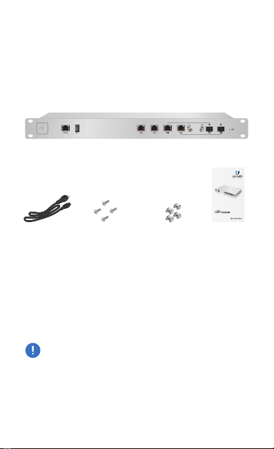
Package Contents
UniFi Security Gateway Pro
Enterprise Gateway Router
with 2 Combination
SFP/RJ45 Ports
Model: USG-PRO-4
Power Cord Mounting Screws
(Qty. 4)
UniFi Controller System Requirements
• Linux, MacOSX, or Microsoft Windows 7/8/10
• Java Runtime Environment 1.6 (or above)
• Web Browser: Google Chrome (Other browsers may have
limited functionality)
• UniFi Controller software v4.8 or higher (available at:
downloads.ubnt.com/unifi)
IMPORTANT: We strongly recommend using UPS backup
and power regulation to prevent equipment damage due
to stability issues with local AC power.
TERMS OF USE: All Ethernet cabling runs must use CAT5 (or above). It is the professional
installer’s responsibility to follow local country regulations and indoor cabling requirements.
Cage Nuts
(Qty. 4)
Quick Start
Guide
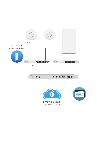
Network Requirement
(UniFi Controller)
Remote Access to
Remote Access to
UniFi Controller
A UniFi Cloud Key or management station running the UniFi
Controller software, located either on-site and connected to
the same Layer-2 network, or off-site in the cloud or NOC
UniFi Cloud Key
UAP-AC-PRO UAP-AC-LR
1G
UniFi Switch
UniFi Switch
LAN
USG-PRO-4
(DHCP Server)
WAN
Internet
Sample Network Diagram
All UniFi devices support off-site management controllers.
For setup details, see the User Guide on our website at:
www.ubnt.com/download/unifi
UAP-AC-M-PRO
UniFi Controller
25 22
597
0.9 116
7 0.94 1
200+0 700+0
msec Mbps
LATENCY THROUGHPUT
DOWNLOAD THROUGHPUT & LATENCY
250
200
150
100
50
Throughput [Mbps]
0
24 HRS 12 HRS NOW
UPLOAD THROUGHPUT & LATENCY
100
80
60
40
20
Throughput [Mbps]
0
24 HRS 12 HRS NOW
126
DEVICES
1G
CURRENT SITE
USERNAME
Default
admin
547
2 118
WAN
LAN WLAN
2290.2
7
118
0.01 413
ACTIVE DEVICE
ACTIVE DEVICES
ACTIVE DEVICES
2.33
Inacve 0
Inacve 0
Inacve 0
Pending
Pending
0
Pending 0
0
SPEED TEST
DEVICES ON 2.4 GHZ CHANNEL
10
Latency [msec]
8
6
1 2 3 4 5 6 7 8 9 10 11
4
2
DEVICES ON 5 GHZ CHANNEL
0
Avg/Max Throughput Latency
36 40 44 48 52 56 60 64
10
Latency [msec]
8
100 104 108 112 116 120 124 128
6
4
2
132 136 140 144 149 153 157 161 165
0
DEEP PACKET INSPECTIONCLIENTSDEVICES
258
582 GB
Motorola
Network Protocols
241
23.3 GB
Lenovo
Streaming Media
WLAN
118
220
22.7 GB
SamsungE
Web / Web 2.0
645 GB
1172
LAN
7
213
8.47 GB
Dell
File Transfer
TRAFFIC
CLIENTS
WAN
1
130
3.6 GB
Acer
Social Network
110
5.46 GB
Other
Other
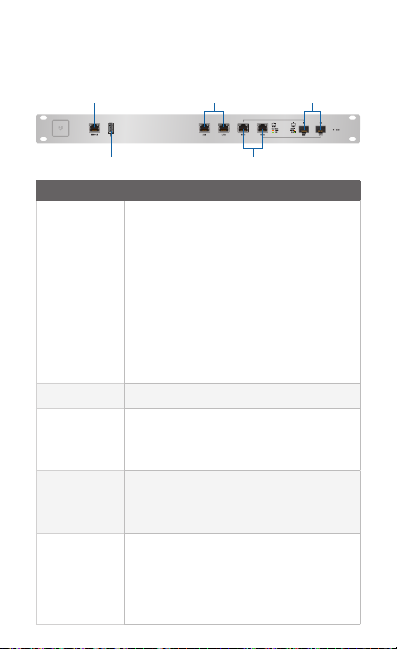
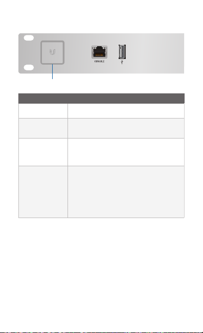
Hardware Overview
Front Panel Ports
Console
LAN
SFP
USB
Interface Description
RJ45 serial console port for Command
Line Interface (CLI) management. Use
an RJ45-to-DB9 serial console cable, also
known as a rollover cable, to connect
the Console port to your computer. Then
Console
configure the following settings as needed:
• Baud rate 115200
• Data bits 8
• Parity NONE
• Stop bits 1
• Flow control NONE
USB Reserved for future use.
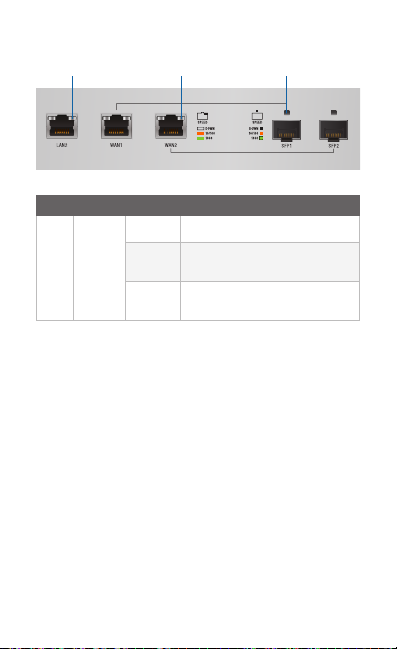
RJ45 ports support 10/100/1000 Ethernet
LAN
WAN
SFP
connections. By default, the LAN1 port is
set to DHCP Server, and its IP address is
192.168.1.1/24.
RJ45 ports support 10/100/1000 Ethernet
connections. A WAN por t is active only if
the corresponding SFP port is empty. By
default, the WAN1 port is set to DHCP Client.
SFP ports are hot-swappable and support
10/100/1000 fiber SFP modules. If an SFP
module is plugged in, then the SFP port is
active, and the corresponding WAN port is
deactivated. By default, the SFP1 port is set
to DHCP Client.
WAN
Front Panel System LED
System
State Status
White Factory defaults, waiting for adoption.
Blue
Alternating
White/Blue
Flashing Blue
Successfully adopted by a network and
working properly.
Device is busy; do not touch or unplug it.
This usually indicates that a process such
as a firmware upgrade is taking place.
This is used to locate a device.
When you click Locate in the UniFi
Controller software, the System LED
will flash blue. The software will also
display the location of the UniFi Security
Gateway Pro on the map.
Front Panel Port LEDs
LED State Status
Off No Link
Speed/
Amber
Link/
Act
LAN / WAN / SFP
Green
*640-00128-04*
SFP: Speed/Link/ActWAN: Speed/Link/ActLAN: Speed/Link/Act
Link Established at 10/100Mbps
Flashing Indicates Activity
Link Established at 1000Mbps
Flashing Indicates Activity
640-00128-04

Front Panel Button
Button Description
Reset
Resets to factory defaults. The UniFi
Security Gateway Pro should be running
after bootup is complete. Press and hold
the Reset button for about 10 seconds
until the right LED on the WAN2 port starts
flashing and then becomes solidly lit.
After a few seconds, the LED will turn off,
and the UniFi Security Gateway Pro will
automatically reboot.
Back Panel
Mounting Holes
Ventilation Holes
Note: There are additional ventilation holes on the sides
of the UniFi Security Gateway Pro.
Fans
Reset
Mounting Holes
Power

Installation Requirements
• Phillips screwdriver
• Standard-sized, 19" wide rack with a minimum of 1U height
available
• For indoor applications, use Category 5 (or above) UTP
cabling approved for indoor use.
• For outdoor applications, shielded Category 5 (or above)
cabling should be used for all wired Ethernet connections
and should be grounded through the AC ground of the
power supply.
We recommend that you protect your networks from
harmful outdoor environments and destructive ESD events
with industrial-grade, shielded Ethernet cable from Ubiquiti
Networks. For more details, visit:
www.ubnt.com/toughcable
WARNING: To reduce the risk of fire or electric shock,
do not expose this product to rain or moisture.
Note: Although the cabling can be located outdoors,
the UniFi Security Gateway Pro itself should be
housed inside a protective enclosure.
 Loading...