

Ubiquiti UAPAC User Manual
Enterprise WiFi System
Model: UAP-AC

Introduction
Introduction
Thank you for purchasing the Ubiquiti Networks™ UniFi Enterprise
WiFi System. The UniFi Enterprise WiFi System includes the UniFi
Controller software, which allows you to manage your wireless
network using your web browser.
This Quick Start Guide is for use with the UniFi AP-AC, model
UAP-AC. The UniFi Enterprise WiFi System also includes the
necessary hardware for mounting the unit on a wall or a ceiling.
The UniFi AP can be powered by the following:
• PoE GigE Adapter (included)
• 48V, 802.3af class 4 compliant switch
• 48V, 802.3at compliant switch
• Ubiquiti Networks TOUGHSwitch PRO, model TS-8-PRO
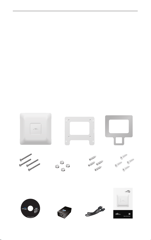
Package Contents
UniFi AP AC Mounting Bracket Ceiling Backing Plate
M3x50 Flat Head
Screws
(Qty. 4)
UniFi Controller
CD with User Guide
M3 Keps Nuts
(Qty. 4)
PoE GigE Adapter
(48V, 0.5A Gigabit)
M2.9x20 Screws
(Qty. 4)
Power Cord Quick Start Guide
M3x20 Screw
Anchors
(Qty. 4)
Enterprise WiFi System
Model: UAP-AC
1
UniFi™ AP-AC Quick Start Guide
System Requirements
• Microsoft Windows XP, Windows Vista, Windows 7, Windows 8,
or Mac OS X
• Java Runtime Environment 1.6 (or above)
• Web Browser: Mozilla Firefox, Google Chrome, or Microsoft
Internet Explorer 8 (or above)
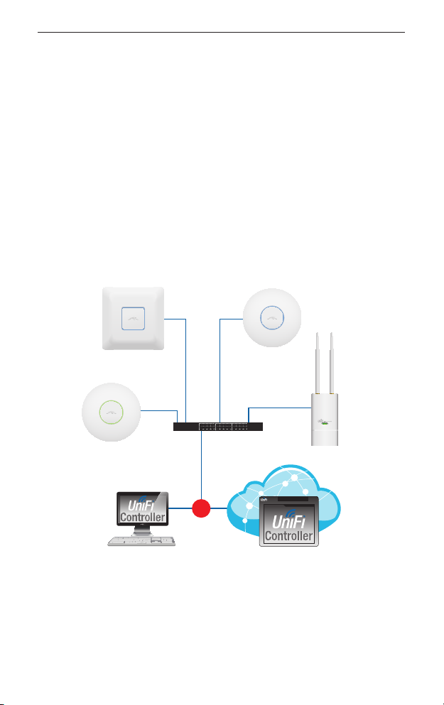
Network Topology Requirements
• A DHCP-enabled network (for the AP to obtain an IP address as
well as for the wireless clients after deployment)
• A management station computer running the UniFi Controller
software, located either onsite and connected to the same
Layer-2 network, or off-site in a cloud or NOC
UAP-AC
UAP/UAP-LR
or
On-Site
Management Station
Sample Network Diagram
UAP-PRO
Router
UAP-Outdoor
O-Site
Cloud/NOC
All UniFi APs support off-site management controllers. Refer to the
User Guide on the CD for setup details.
2
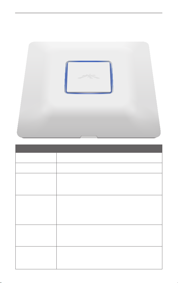
Hardware Overview
Hardware Overview
LED
LED Color Status
Flashing white Initializing.
Steady white Factory default, waiting to be integrated.
Alternating
white/blue
Quickly flashing
blue
Steady blue Indicates the device has been successfully
Steady blue
with occasional
flashing
Device is busy; do not touch or unplug it.
This usually indicates that a process such as a
firmware upgrade is taking place.
This is used to locate an AP.
When you click Locate in the UniFi Controller
software, the AP will flash. It will also display
the location of the AP on the map.
integrated into a network and is working
properly.
Indicates the device is in an isolated state (all
WLANs are brought down until an uplink is
found).
3
UniFi™ AP-AC Quick Start Guide
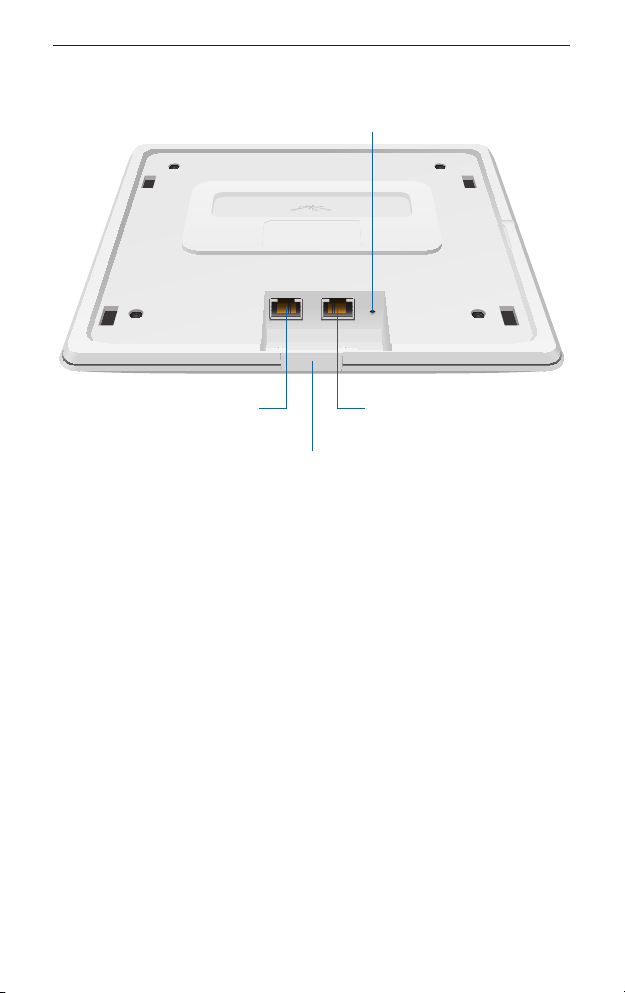
Ports
Reset Button
Main/48V Secondary
Main/48V Port
Cable Feed Plug
Reset
Secondary Port
Main/48V The Main/48V port is a Gigabit Ethernet port used
to connect the power and should be connected to the LAN and
DHCP server. Power can be provided by the following:
• PoE GigE Adapter (included)
• 48V, 802.3af class 4 compliant switch
• 48V, 802.3at compliant switch
• Ubiquiti Networks TOUGHSwitch PRO, model TS-8-PRO
Secondary The Secondary port is a Gigabit Ethernet port used for
bridging.
Reset The Reset button serves two functions:
• Restart It will restart the device when you press and release it
quickly.
• Restore Factory Defaults When you press and hold it for more
then 5 seconds, it will restore the device to the factory default
settings.
Cable Feed Plug If your Ethernet cable feeds along the mounting
surface, remove the Cable Feed Plug.
4
Installation Requirements
Installation Requirements
• CAT5/6 cable
• Drill and drill bit (6 mm for wall-mounting or 3 mm for
ceiling-mounting)
Hardware Installation
The UniFi AP can be mounted on the wall or ceiling. Perform the
steps for the appropriate installation:
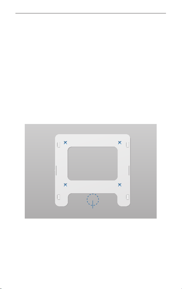
Wall Mount
1. Position the Mounting Bracket at the desired location on the
wall with the cable feed slot pointed towards the floor.
2. Use a pencil to mark the four holes on the wall. Use a 6 mm drill
bit to drill the holes.
Top
Optional 25 mm Hole for
Ethernet Cable Feed through Wall
3. Follow the instruction for your type of Ethernet cable feed:
- Feeds Through the Wall Cut or drill a circle approximately
25 mm in diameter, just below the bottom center of the
Mounting Bracket (as shown above). Then feed the CAT5/6
cable through the hole.
- Feeds Along the Mounting Surface Remove the Cable
Feed Plug on the side of the UniFi AP.
5
UniFi™ AP-AC Quick Start Guide
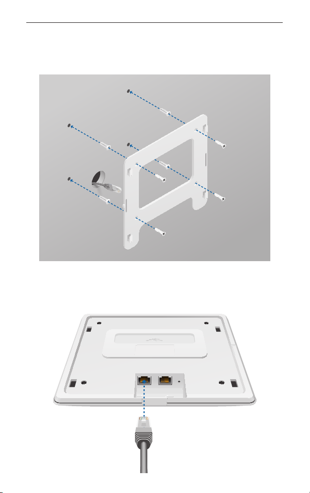
4. Insert the M3x20 Screw Anchors into the 6 mm holes. Secure the
Mounting Bracket to the wall by inserting the M2.9x20 Screws
into the anchors.
5. Connect one end of the Ethernet cable to the Main/48V port on
the UniFiAP. If the feed is along the mounting surface, feed the
cable through the Cable Feed of the UniFi AP.
6
Main/48V Secondary
Reset
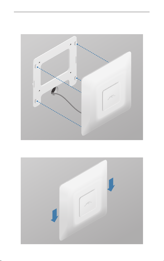
Hardware Installation
6. Align the slots on the UniFi AP with the tabs on the Mounting
Bracket.
7. Slide the UniFi AP down until it locks into place.
7
 Loading...