

Ubiquiti ES-10XP, ES-10X Quick Start Guide
8-Port Gigabit Switch with PoE
Passthrough and 2 SFP Ports
Model: ES-10X
Introduction
Thank you for purchasing the Ubiquiti Networks® EdgeSwitch®
10X. This Quick Start Guide is designed to guide you through
installation and also includes warranty terms.
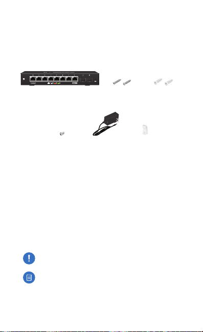
Package Contents
EdgeSwitch 10X Wall Mount
Ground Screw Power Adapter
Screws (Qty. 2)
(24V, 1A)
Anchors (Qty. 2)
Cable Clip
Wall Mount
Installation Requirements
• For indoor applications, use Category 5 (or above) UTP
cabling approved for indoor use.
• For outdoor applications, shielded Category 5 (or above)
cabling should be used for all wired Ethernet connections
and should be grounded through the AC ground of the
power supply.
We recommend that you protect your networks from
harmful outdoor environments and destructive ESD events
with industrial‑grade, shielded Ethernet cable from Ubiquiti
Networks. For more details, visit: www.ubnt.com/toughcable
WARNING: To reduce the risk of fire or electric shock,
do not expose the EdgeSwitch to rain or moisture.
Note: Although the cabling can be located outdoors,
the EdgeSwitch itself should be housed inside a
protective enclosure.
TERMS OF USE: All Ethernet cabling runs must use CAT5 (or above). It is the professional
installer’s responsibility to follow local country regulations, including operation within legal
frequency channels, output power, indoor cabling requirements, and Dynamic Frequency
Selection (DFS) requirements.
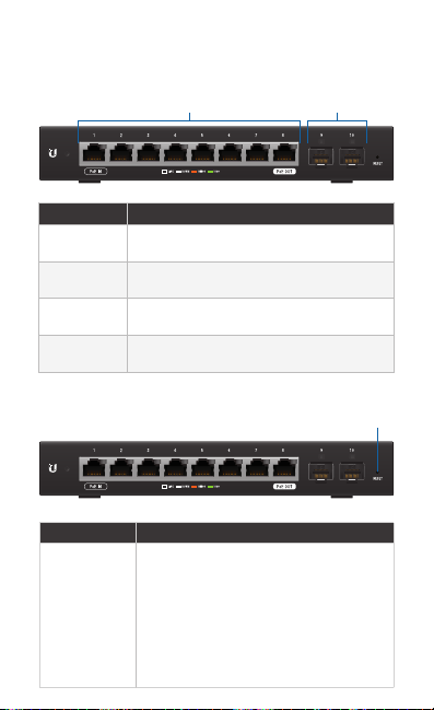
Hardware Overview
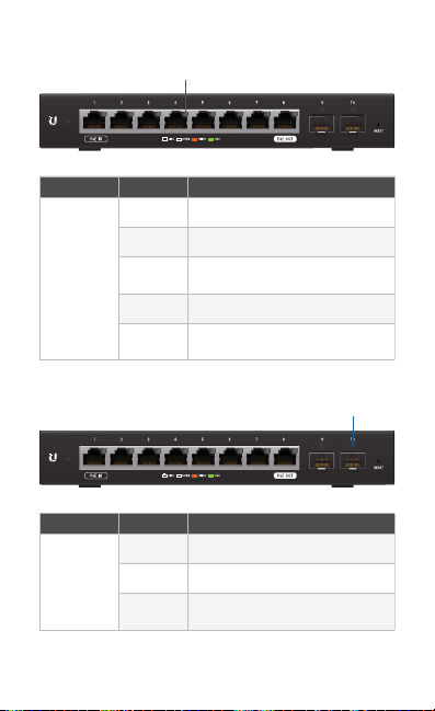
Front Panel Ports
RJ45 Ports 1-8
Interface Description
RJ45 1‑8 RJ45 por ts support 10/100/1000 Ethernet
PoE In
(Port 1)
PoE Out
(Port 8)
SFP 9‑10 Hot‑swappable SFP ports support 1 Gbps
connections.
Supports 24V Passive PoE input.
Supports 24V Passive PoE passthrough.
connections.
Front Panel Button
SFP Ports 9-10
Reset
Button Description
Reset
To reset to factory defaults:
1. Disconnect power from the EdgeSwitch.
2. Reconnect power while holding the
Reset button. The port LEDs will light
up in sequential order (this takes
approximately five seconds).
3. When the port 1 LED flashes again,
release the Reset button.
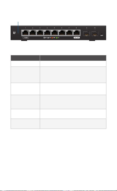
Front Panel LEDs
System
System LED
State Status
Flashing White Bootup in Progress
White
Blue
Steady Blue
with Occasional
Flashing
Quickly Flashing
Blue
Alternating
Blue/White
You can use the EdgeSwitch Configuration Interface or UNMS
to manage your device. UNMS lets you configure, monitor,
upgrade, and back up your devices using a singleapplication.
Get started at www.unms.com
Ready for Use
Not Connected to Ubiquiti® Network
Management System (UNMS™)
Ready for Use
Connected to UNMS
Ready for Use
Unable to Connect to UNMS
Used to Locate a Device in UNMS
Firmware Upgrade in Progress
RJ45 LEDs
Speed/Link/Activity
LED
Speed/
Link/
Activity
SFP LEDs
LED
Link/
Activity
State Status
Off No Link
Amber Link Established at 10/100 Mbps
Amber
Flashing
Link Activity at 10/100 Mbps
Green Link Established at 1000 Mbps
Green
Flashing
Link Activity at 1000 Mbps
Link/Activity
State Status
Off No Link
Green Link Established at 1 Gbps
Green
Flashing
Link Activity at 1 Gbps
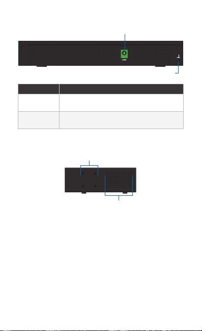
Back Panel
Power
Grounding Point
Interface Description
Power Connect the included Power Adapter to the
Grounding
Power port.
Ground bonding point for an optional
Point
ground wire.
Side Panel
Bracket Mounting
Holes
Ventilation
Holes
Hardware Installation
The EdgeSwitch can be placed on a horizontal surface,
mounted on a wall, or mounted in a rack (brackets not
included). The optional EdgeRouter™ Rackmount Kit, model
ER‑RMKIT, is sold separately.
Follow the Wall Mounting instructions to mount the
EdgeSwitch using the included screws and anchors.
WARNING: FAILURE TO PROVIDE PROPER VENTILATION
MAY CAUSE FIRE HAZARD. KEEP AT LEAST 20 MM OF
CLEARANCE NEXT TO THE VENTILATION HOLES FOR
ADEQUATE AIRFLOW.
WARNING: The EdgeSwitch ES‑10X must not be stacked.
Do not place it on top of another switch. Do not place
anything on top of the ES‑10X.
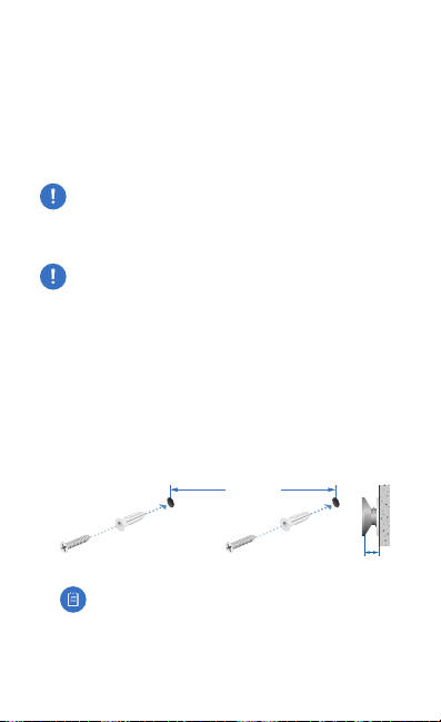
Wall Mounting
To mount the EdgeSwitch on a wall, you will need a drill, a
6mm drill bit, and a Phillips screwdriver.
1. Use a 6 mm drill bit to drill two holes 148 mm apart.
2. Insert the Wall Mount Anchors into the holes. Use a Phillips
screwdriver to secure a Wall Mount Screw to each anchor.
Leave a clearance of approximately 3 mm between each
screw head and its anchor.
148 mm
3 mm
Note: You can also mount the EdgeSwitch in a
vertical orientation.
 Loading...