


1. SPECIFICATIONS
ITEM |
|
|
TAS-12H |
TAS-15H |
TAS-18H |
TAS-24H |
|
|
|
|
|
|
|
|
|
Function |
|
|
|
Cooling & Heating |
|
||
|
|
|
|
|
|
|
|
Capacity |
|
BTU/H |
11,500 / 12,000 |
14,500 / 15,000 |
17,500 / 18,000 |
21,500 / 22,000 |
|
|
|
|
|
|
|
|
|
SEER |
|
|
10.0 |
10.0 |
10.0 |
10.0 |
|
|
|
|
|
|
|
|
|
H.S.P.F |
|
|
6.8 |
6.8 |
6.8 |
6.8 |
|
|
|
|
|
|
|
|
|
Dehuminication |
L/H |
1.5 |
1.8 |
2.5 |
3.0 |
||
|
|
|
|
|
|
|
|
Electrical Data |
|
|
|
|
|
||
|
|
|
|
|
|
|
|
|
|
Main Power |
|
|
AC 208/230V~ , 60Hz , 1 Ph |
|
|
|
|
|
|
|
|
|
|
|
|
Running Current |
A |
5.0/5.4 |
6.5/6.6 |
8.0/8.0 |
10.0/10.3 |
|
|
|
|
|
|
|
|
|
|
Watts |
W |
1,130 / 1,230 |
1,470 / 1,500 |
1,800 / 1,780 |
2,210 / 2,280 |
|
|
|
|
|
|
|
|
Refrigerant |
|
|
|
R-22 |
|
||
|
|
|
|
|
|
|
|
|
|
Quantity |
OZ |
38.8 (1100g) |
41.62 (1180g) |
43.39 (1230g) |
64.55 (1830g) |
|
|
|
|
|
|
|
|
|
|
Connection |
|
|
Flare |
|
|
|
|
|
|
|
|
|
|
|
|
Gas Side |
inch |
3/8" (9.52mm) |
1/2" (12.7mm) |
1/2" (12.7mm) |
5/8" (15.9mm) |
|
|
|
|
|
|
|
|
|
|
Liquid Side |
inch |
1/4" (6.35mm) |
1/4" (6.35mm) |
1/4" (6.35mm) |
3/8" (9.52mm) |
|
|
|
|
|
|
|
|
Compressor |
|
QK173KAB |
QJ222KCC |
48D185IU1EH |
QP325KBB |
||
|
|
|
|
|
|
|
|
|
|
O.L.P |
|
MRA 98996-12026 |
MRA 12074-12027 |
MRA12149-12007 |
Internal |
|
|
|
|
|
|
|
|
|
|
LRA |
A |
29 |
34 |
43 |
68 |
|
|
|
|
|
|
|
|
Motor |
|
Indoor |
|
FDA353DWA |
FDA353DWB |
FDA353DWC |
|
|
|
|
|
|
|
|
|
|
|
Outdoor |
|
YDK-50-6A1 |
YDK-50-A1 |
YDK-50-A1 |
A2929GS010 |
|
|
|
|
|
|
|
|
Capacitor Dual |
|
3/25µF 400VAC |
3/35µF 400VAC |
3/40µF 400VAC |
5/40µF 400VAC |
||
|
|
|
|
|
|
|
|
Dimension |
|
|
Unit conversion : 1 inch = 25.4 mm |
|
|||
|
|
|
|
|
|
|
|
Indoor |
|
W x H x D |
mm |
815x285x195 |
1035x322x205 |
1080x298x200 |
1080x298x200 |
|
|
|
|
|
|
|
|
|
|
Weight (net) |
lb |
20.3 (9.2kg) |
26.7 (12.1kg) |
32.4 (14.7kg) |
32.4 (14.7kg) |
|
|
|
|
|
|
|
|
Outdoor |
|
W x H x D |
mm |
800x615x320 |
800x615x320 |
800x615x320 |
872x675x325 |
|
|
|
|
|
|
|
|
|
|
Weight (net) |
lb |
110.3 (50kg) |
110.3 (50kg) |
110.3 (50kg) |
141.1 (64kg) |
|
|
|
|
|
|
|
|
The Ranges of Temperature And Humidity.
Indoor Temp |
Outdoor Temp |
Indoor Humidity |
|
|
|
65~90°F |
70~109°F |
Less than 80% |
|
|
|
(18~32°C) |
(21~43°C) |
|
|
|
|
Standard Rating Condition
Indoor |
|
Outdoor |
||
DB |
|
WB |
DB |
WB |
80°F |
|
67°F |
94°F |
75°F |
|
|
|
|
|
(26.7°C) |
|
(19.4°C) |
(35.0°C) |
(23.9°C) |
|
|
|
|
|
1
2. INSTALLATION
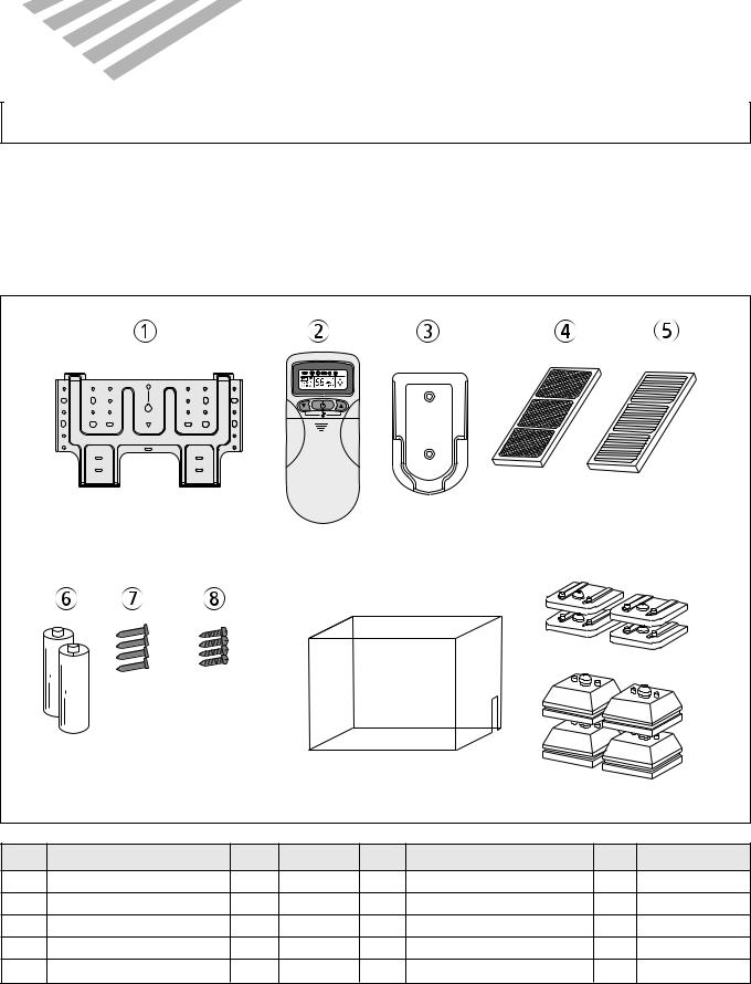
BASIC ACCESSORIES
This Installation section explains how and where to connect this new air conditioner. Please read make sure all accessories are included as shown below and read manual thoroughly. This Installation section is provided to assist the person knowledgeable in air conditioner installation and should not be installed by anybody who is not thoroughly familiar with this type of installation. Please contact a professional installer if necessary.
ACCESSORIES SUPPLIED WITH THE UNIT:
|
|
|
AUTO |
|
|
|
|
|
|
|
|
|
|
0 |
|
|
|
|
|
9 |
|
|
|
|
|
|
|
|
|
(24 Series Only) |
|
No |
Part Name |
Q'ty |
Remark |
No |
Part Name |
Q'ty |
Remark |
1 |
Installation Plate |
1 |
|
6 |
Battery |
2 |
|
2 |
Remote Controller |
1 |
|
7 |
Nail |
4 |
|
3 |
Remote Holder |
1 |
|
8 |
Screw |
4 |
|
4 |
Deodorizing Filter |
1 |
|
9 |
Outdoor Cover |
1 |
|
5 |
Electrostatic Filter |
1 |
|
10 |
Foot Cushion |
4 |
|
|
|
|
|
2 |
|
|
|
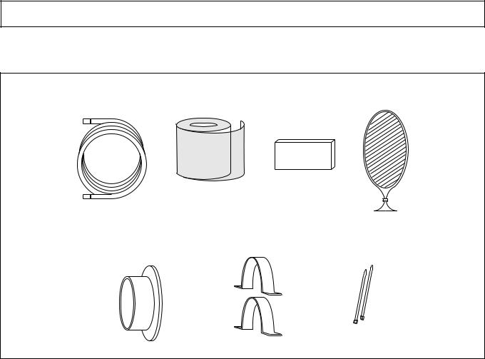
OPTIONAL ACCESSORIES
ACCESSORIES NOT SUPPLIED WITH THE UNIT:
1 |
2 |
3 |
4 |
5 |
6 |
7 |
No |
Part Name |
Q'ty |
Description |
Remark |
1 |
Drain Hose Extension |
1 |
PVC, 20mm x 2M |
|
|
|
|
|
|
2 |
Tape Finish |
1 |
PVC, W80mm x 25M |
|
|
|
|
|
|
3 |
Insulator Plate |
1 |
PE, T8.0 |
|
|
|
|
|
|
4 |
Putty |
1 |
Gray, 80g |
|
|
|
|
|
|
5 |
Wall Cap |
1 |
HIPS, |
|
|
|
|
|
|
6 |
Bracket Saddle |
2 |
SCT, T0.8 |
TAS-24H Only |
|
|
|
|
|
7 |
Cable Tie |
2 |
DACT-190A |
TAS-24H Only |
|
|
|
|
|
3
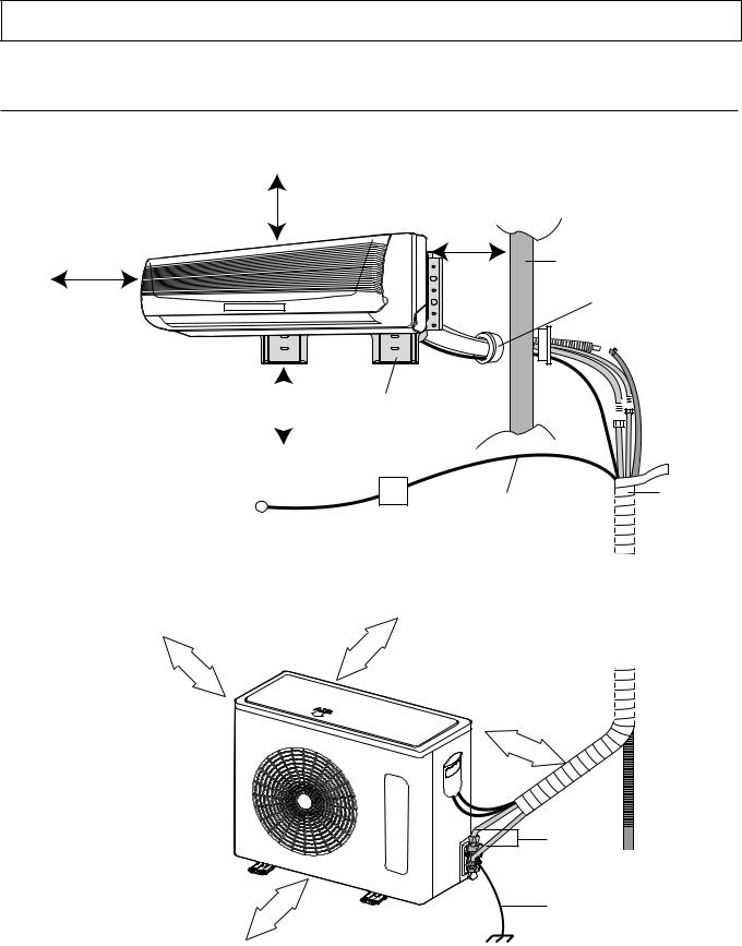
INSTRUCTION OF INSTALLATION
Below is an overview for the connection of the Indoor unit to the Outdoor unit.
OVERVIEW
This appliance must be installed according to national power supply acquirement.
10cm (3.95in)
from ceiling 30cm (11.8in) from side wall
10cm (3.95in) from |
Wall |
|
side wall |
||
|
Wall Cap
(Not Supplied)
At least 30cm |
Installation Plate |
|
|
|
|
(11.8in) from unit |
|
|
|
|
|
|
|
|
|
||
|
|
|
|
|
|
|
|
|
|
|
|
|
|
|
|
|
|
|
|
|
|
|
|
Power |
|
Power cable |
Wrap with |
|
|
Tape |
|||
Source |
Circuit Breaker |
|||
(Not Supplied) |
||||
(Not Supplied) |
||||
|
|
|
10 |
cm |
|
more than 4 inch
60 cm
more than
4 inch |
10 |
|
cm |
||
|
more than 24 inch
Maximum Height |
7M (21Ft) |
Maximum Length |
15M (49Ft) |
Standard Length: 25ft (7.6m)
Adding Refrigerant: 0.32 oz/ft (30g/m)
Adding additonal tubing will decrease efficiency.
more than 27 inch
70 |
cm |
Copper |
|
|
|
Drain |
|
|
|
||
|
|
|
||
|
|
|
||
Tubing |
|
|
|
|
|
|
|
Hose |
|
|
|
|
||
|
|
|
|
(Not Supplied) |
(Not Supplied) |
Ground Wire |
|
(Not Supplied) |
|
4
INSTALLATION
SELECTING A SITE:
INDOOR UNIT
•Do not install the unit in an area with direct sunlight, near heat sources (radiator, etc.), or an area where leakage of flammable gas may be expected.
•Select a position in the room, high on the wall, where the whole room can be uniformly cooled.
•Select a location that can hold the weight of the unit and where the copper tubing, drain hose and Indoor to Outdoor Wire have the shortest distance to the Outdoor unit.
•Make sure the Indoor unit is installed at least 10cm (3.95in) away from the top and left side wall and at least 30cm (11.8in) from AC outlet and right side wall.
OUTDOOR UNIT
•Do not install the unit in an area near heat sources, exhaust fans, or an area where leakage of flammable gas may be expected.
•Do not install the unit in a humid, damp or uneven location.
•Select a location that is well ventilated .
•Leave enough room around the unit for air intake, exhaust and possible maintenance.
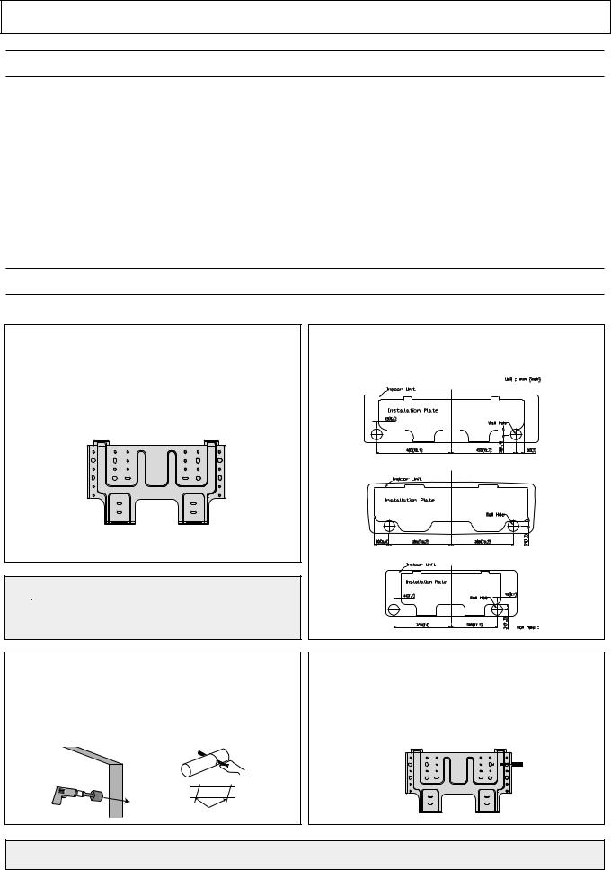
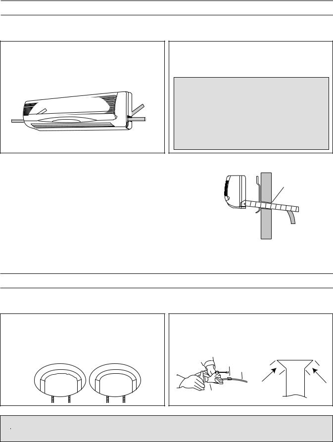
INSTALLING THE INSTALLATION PLATE
To install the wall bracket, follow the procedures below. One hole is required for the tubing and may be either on the left or right side.
1.Determine the type of wall (sheetrock, concrete, etc.) and make sure it is strong enough to hold indoor unit. Select an approximate position for the unit, taking the required distances away from walls/AC outlet into consideration.
 CAUTION
•Before making hole, make sure there are no studs, pipes, electrical wiring or conduit directly behind the area to be cut.
2.Determine if the hole is to be made at the left or right hole location.
••TASTAS-18,-18/2424H
• •TASTAS-15H-
• •TASTAS-12H-
70(2.75)
3.Using drill with hole-cutting attachment or equivalent, cut a hole 70mm (2.75") in diameter. The hole should be made at a slight downward slant to the outdoor side. Measure the thickness from the inside to outside edges and cut a PVC pipe at a slight angle 1/4" shorter than the thickness of the wall and insert pipe in wall.
4.For sheetrock, wooden or similar wall, measure down from the ceiling using a level or tape measure and attach the wall bracket to the wall using 4 screws. If you are not able to line up the holes with the beams, use toggle bolts. Make sure the wall bracket is even and flush against the wall.
Indoor Outdoor
Cut at slight angle
For Concrete, or similar type wall, make holes into the wall and insert concrete nails instead of screws.
5
MOUNTING THE INDOOR UNIT
The Indoor unit must be mounted before connecting the indoor/outdoor wire, drain hose and copper tubing. To mount, follow the procedures below:
1.The tubing can be extended in 4 directions as shown below. No cutting is necessary for left/rear and right/rear tubing connections. If using left or right tubing connections, remove the plastic area with a hacksaw so pipes can go through.
|
|
Right/Rear |
|
Left/Rear |
Tubing |
|
|
|
Left |
Tubing |
Right |
Tubing |
|
Tubing |
2.Make sure the drain hose and copper tubing are wrapped with the rubber insulation. Using the tape, wrap the indoor/outdoor wire, copper tubing and drain hose together.
 CAUTION:
•Make sure the Indoor unit’s AC cord is not connected to AC power when performing these procedures.
•Be sure to comply with local codes on running a wire from the indoor to the outdoor unit.
•DO NOT LET THE INDOOR/OUTDOOR WIRE COME IN DIRECT CONTACT WITH THE TUBING OR HOSE!
3. Shape the tubing so it can easily go through the hole |
|
|
|
|
Installation Plate |
|
|||
in the wall. Push the indoor/outdoor wire, copper tub- |
|
|||
|
|
|
|
|
|
|
|
|
|
ing and drain hose through the hole in the wall angling |
|
Insert Putty |
|
|
downward. Situate the indoor unit on the wall bracket |
|
|
|
|
by lifting the indoor unit slightly above the wall bracket |
|
|
|
|
and then down so it is securely locked in place. |
|
|
|
|
|
|
|
|
|
|
|
|
|
|
|
|
Drain Hose |
|
|
|
|
|
|
|
|
|
|
|
|
PREPARING THE COPPER TUBING (NOT INCLUDED)
A copper tubing extension (not included) may need to be cut. If this is the case, it will also have to be deburred and flared as shown below:
1. Cut the copper tube extension to the desired length |
2. Make a flare at the end of the copper tube with a flare |
|
with a tube cutter. It is highly recommended that 1 foot |
tool. |
|
is added to the requested length. After cutting, debur- |
Make sure the inside surface and edges are smooth |
|
ring may be necessary (see below diagram). Perform |
and the sides are uniform length. |
|
this with a tube reamer. |
|
|
BEFORE |
AFTER |
Flare nut |
|
|
|
|
|
Connection |
|
|
pipe |
Flare tool |
 CAUTION:
• When using the tube reamer, hold the tube downward and make sure no copper scraps fall into the tubing.
6

CONNECTING THE COPPER TUBES
To connect the copper tubes, follow the procedures below:
1.Remove the flare nut stoppers from the inside unit. Determine the location of the copper tubing and where the bends will be. Gently bend the copper tubing, making sure to use big angles so no crimping will occur. Try to do this on the first try as repeated bending may break or crimp the tubing.
2.Remove the plastic stoppers from the tubing. Connect the large and small copper tubing to the respective extension and rotate the flare nut with your finger until a smooth match is made. Make sure the copper extension has foam rubber (insulation) on it.
|
|
|
|
|
|
|
|
|
|
|
|
|
|
|
|
|
|
|
|
|
|
|
|
|
|
|
coupler |
Flare Nut |
|||||||
|
|
|
|
|
|
|
|
|
NOTE:
When removing the flare nut stopper from the inside unit, confirm “Ping”, sounds because the mixed gas is charged in the inside unit,
3.Once a smooth match is made, tighten the flare nut using a wrench. Be very careful not to strip the threads or flare nut. Repeat this process for the small and large tubing. When tightening the flare nut, use another wrench to securely hold the coupler from twisting and possibly damaging the tubing.
5.Perform a leak test on all copper tube connections. To prevent heat loss and damage to walls from condensation, the copper tube connections coming from the wall must be insulated. Do this by wrapping foam rubber or equivalent around the connection approximately 8mm thick so no copper tubing is exposed.
4.Remove the flare nut stoppers from the outdoor unit’s valves. Connect the larger copper tubing to the larger valve on the outdoor unit. Connect the smaller copper tubing to the smaller valve on the outdoor unit.
NOTES:
•As with all wiring and hookups on this unit, make sure the AC plug on the indoor unit is unplugged.
•Be very careful not to strip the threads or flare nut.
•When insulating the connections, use foam rubber or equivalent.
CONNECTING THE DRAIN HOSE
To connect the drain hose, follow the procedures below:
1.Connect the drain hose extension to the drain hose coming from the indoor unit by loosing the clamp on the extension using a phillips screwdriver, attaching the hoses together and then tightening the clamp.
2.Run the drain hose, slanted downward, outside. If the drain pipe is exposed
indoors, make sure it is thoroughly insulated so
condensation does not ruin walls or furniture or come in contact with the AC connection or extension. Also, do not crease or form a trap in the tubing.
7
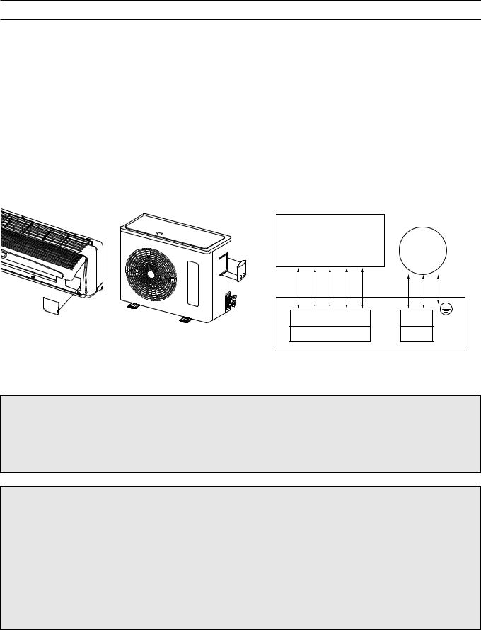
CONNECTING THE CABLES
One electric power cable must be connected to the outdoor unit. The indoor unit is connected to outdoor unit through the connection cable. To install the cables follow as below.
1.Open the connection cover on the indoor unit.
2.Open the SVC cover on the side of outdoor unit.
3.Connect the connection cable to terminal blocks of the indoor and outdoor unit as shown below.
-Must be connected with the same terminal number of indoor and outdoor unit.
-Be sure not to slip the cables out of terminal.
4.Connect the power cable and earth cable.
5.Reinstall the connection cover and the SVC cover.
6.Install the conduit kit. (The conduit kit is optional)
[Connetion Cable]
Indoor Unit
Terminal Block |
|
||||
|
|
|
|
|
Circuit breaker |
1 |
2 |
3 |
4 |
5 |
|
|
|
|
|
|
(Main Power) |
|
|
|
|
|
|
1  2
2  3
3  4
4  5
5
Terminal Block
L  N
N
T/B 2
Outdoor Unit
CAUTION
•The supply voltage must be the same as the rated voltage of air conditioner.
•Prepare the power source for exclusive use with the air conditioner.
•A circuit breaker must be installed between the power source and the unit.
•This air conditioner must be installed according to the national electric rules.
INFORMATION
• The information for the cables of this air conditioner is as below.
ITEM |
SPECIFICATIONS |
||
|
|
|
|
POWER CABLE |
12K~15K BTU/h |
3G AWG 14 SJT or SPT-3 |
|
|
|
||
18K~24K BTU/h |
3G AWG 12 SJT or SPT-3 |
||
|
|||
|
|
|
|
CONNECTION CABLE |
12K~24K BTU/h |
5G AWG 16~18 SJT |
|
3G AWG 18~20 SJT+2G AWG 16~18 SJT |
|||
|
|
||
|
|
|
|
CONDUIT SIZE |
0.875 inch (22.2mm) |
||
|
|
|
|
8
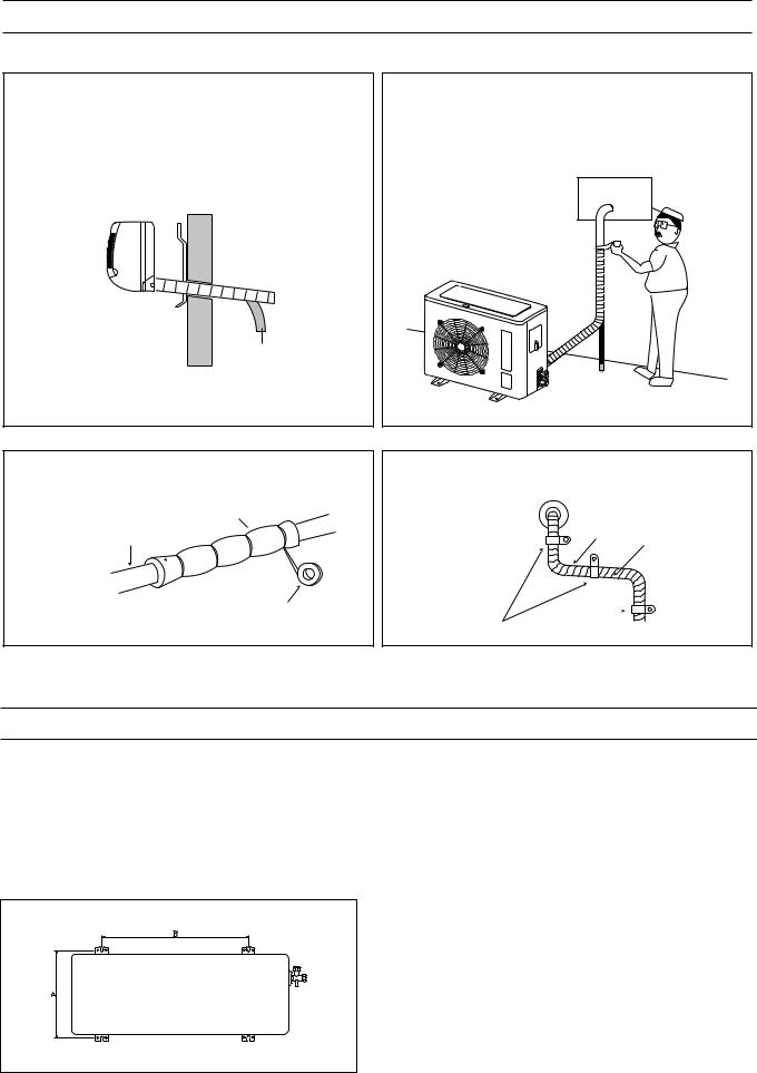
TAPING UP THE WIRE/TUBES/HOSE
After running the wire, hose and tubing outside, tape them up as shown below to insulate.
1.Tape the two copper tubes, drain hose (and the electrical wiring if local codes permit) together with the supplied tape. Make sure the electrical wiring does not come in direct contact with the copper tubing or drain hose. Approximately 1 foot outside the hole, let the drain hose out and separate from the copper tubing and wiring.
2.Begin wrapping from the point the tubing comes out of the outdoor unit and continue to the hole in the wall. Leave no gaps or breaks and cover the entire length of the tubing. As you wrap, overlap the previous turn by half the width of the tape.
Drain hose
3.Wrap the piping joints with the insulator plate and fas
ten it with vinyl tape.
Plate
pipe
vinyl tape
4.After wrapping the connection pipe with tape, fasten it to the outside wall with saddles, etc.
Wall cap
Pipe
Tape
Saddle (Not supplied)
MOUNTING OUTDOOR UNIT
1.After selection the appropriate site, position the outdoor unit and make sure the space around the outdoor unit. (See overview instruction of installation)
2.Mount the outdoor unit on appropriate base using anchor bolts.
3.Install the CUSHION RUBBER provided to prevent vibration and noise.
4.If the outdoor unit is expose to direct sunlight or strong wind, install shield around the outdoor units.
The outdoor unit must be installed on stable and rigid base.
(inch)
Model |
A |
B |
|
|
|
TAS-12/15/18H |
14.17 |
22.83 |
|
|
|
TAS-24H |
13.78 |
21.65 |
|
|
|
9
APPLYING PUTTY AND INSERTING THE WALL CAP
After running the wires and tubing outside, putty should be inserted around the opening on the outside to protect against rain, wind, etc. To apply putty, see below:
1.Apply the putty to any area on the outside hole that air or rain can get into.
Apply Putty
Here
Tubing
2. After applying putty, |
|
insert the wall Cap at |
Insert Putty |
Indoor side |
|
and Outdoor side. |
|
Wall Cap |
|
(For DS-110R) |
Drain Hose |
Indoor side Wall |
Outdoor side |
Indoor Unit |
|
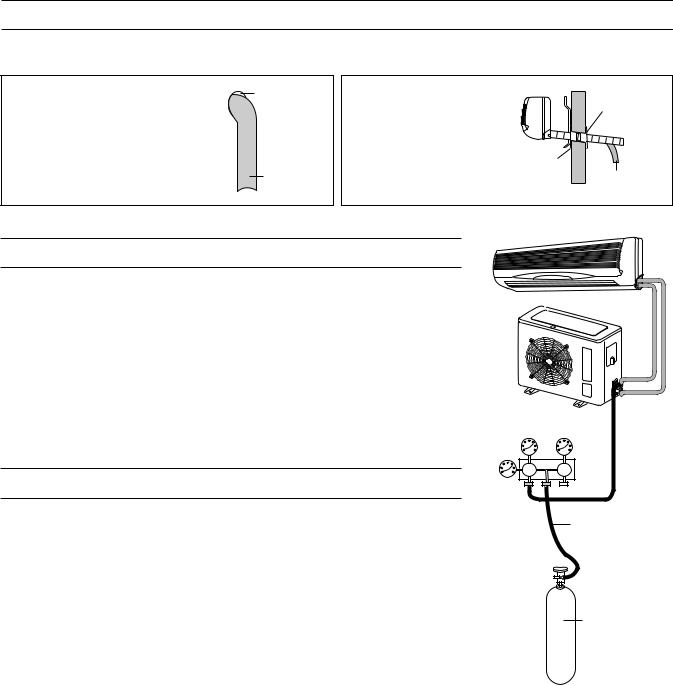
AIR PURGING
Air and moisture remaining in the refrigerant system may create adverse conditions as indicated below:
•pressure in the system rises
•operating current rises
•cooling efficiency drops
• moisture in the refrigerant circuit may freeze and block capillary tubing
• water may lead to corrosion of parts in the refrigerant system
Therefore, the indoor unit and tubing between the indoor and outdoor unit must be leak tested and evacuated to remove any noncondesables and moisture from the system.
Outdoor Unit
Manifold Valve
AIR PURGING WITH VACUUM PUMP (TEST RUN)
Pressure |
Lo |
Hi |
|
Gauge |
|||
|
|
Confirm each tube (narrow and wide tubes) between the indoor and outdoor units has been properly connected and all wiring for the test run has been completed. Remove the valve caps from the wide and narrow service valves on the outdoor unit. Note that both narrow and wide tube service valves on the outdoor unit are kept closed at this stage (shipping position).
Leak Test
1.With the service valves on the outdoor unit remaining closed, remove the threaded cover on the wide tube service port. (Save for reuse.)
2.Attach a manifold valve (with pressure gauge) and dry nitro gen gas cylinder to this service port with charge hoses.
Charge Hose
Nitrogen Gas Cylinder (Vertical Position)
CAUTION:
Be sure to use a manifold valve for air purging. If it is not avail able, use a stop valve for this purpose. The Hi knob of the manifold valve must always be kept closed.
3.Pressurize the system to no more than 150 P.S.I.G. with dry nitrogen gas and close the cylinder valve when the gauge reading reaches 150 P.S.I.G. Next, test for leaks with liquid soap.
CAUTION:
To avoid nitrogen entering the refrigerant system in a liquid
state, the top of the nitrogen gas cylinder must be higher than its bottom when you pressurize the system. Usually, the cylinder is used in a vertical standing position.
4.Do a leak test of all joints of the tubing (both indoor and outdoor) and both wide and narrow service valves. Bubbles indicate a leak. Be sure to wipe off the soap with a clean cloth.
5.After the system is found to be free of leaks, relieve the nitrogen pressure by loosening the charge hose connector at the nitrogen cylinder. When the system pressure is reduced to normal, disconnect the hose from the cylinder.
10
Evacuation
Indoor Unit
1.Attach the charge hose end described in the leak test area to a vacuum pump to evacuate the tubing and indoor unit. Confirm the Lo knob of the manifold valve is open. Then, run the vacuum pump. The operation time for evacuation varies with the tubing length and capacity of the pump. The following table shows the amount of time for evacuation:
Outdoor Unit
Required time for evacuation when 30 gal/h vacuum pump is used
If tubing length is less than |
If tubing length is longer than |
33 ft. (10 m) |
33 ft. (10 m) |
|
|
10 min. or more |
15 min. or more |
|
|
2.When the desired vacuum is reached, close the Lo knob of the manifold valve and stop the vacuum pump.
Manifold Valve
Finishing the job
1. With a hex wrench, turn the narrow tube service valve |
Pressure |
stem counter-clockwise to fully open the valve. |
Gauge |
2.Turn the wide tube service valve stem counter-clockwise to fully open the valve.
CAUTION:
To avoid gas from leaking when removing the charge hose, make sure the wide tube service valve is fully open and turned all the way out.
3.Loosen the charge hose connected to the wide tube service port slightly to release the pressure, then remove the hose.
4.Replace the threaded cover on the wide tube service port and fasten it securely. This process is very important to prevent gas from leaking from the system.
5.Replace the valve caps at both wide and narrow service valves and fasten them securely.
This completes air purging with a vacuum pump. The air conditioner is now ready to test run..
Lo  Hi
Hi
Charge Hose
Vacuum
Pump
11
TEST RUN
Check that all tubing and wiring have been completed correctly. Check again that the wide and narrow tube service valves are fully opened. Turn on the power and run the system.
Service Valve Construction
•Valve Position Closed
The valve systems of both the wide and narrow tubes are turned all the way in. The unit is shipped from the factory in this position and it is also used for Pump Down and Air Purging.
•Valve Position Fully Open
The valve stems of both the wide and narrow tubes are turned all the way out. This is normal operating and Test Run position.
•Valve Position Half Open
With the narrow tube valve stem is turned to the halfway-down position. This position is used for pressure measurement and gas charging.
CAUTION:
When opening or closing the service valve stem, be sure to use a hex wrench.
PUMP DOWN
Pump Down means collecting all refrigerant in the outdoor unit without loss in refrigerant gas. This is performed when the unit is to be relocated or the refrigerant circuit is serviced.
 CAUTION:
Be sure to perform Pump Down procedure with the unit cooling mode.
Pump Down Procedure
1.Connect a low-pressure gauge manifold hose to the charge port on the wide tube service valve.
2.Open the wide tube service valve halfway and purge the air from the manifold hose using the refrigerant gas.
3.Close the narrow tube service valve (all the way in).
4.Turn on the unit s operating switch and start the cooling operation.
5.When the low-pressure gauge reading becomes 1 to 0.5 kg/cm2 (14.2 to 7.1 psi), fully close the wide tube valve stem and then quickly turn off the unit. At that time, Pump Down has been completed and all refrigerant gas will have been collected in the outdoor unit.
12

3. REFRIGERANT CYCLE DIAGRAM
Pipe Size (Dimension-inch) |
|
Max. Piping length |
Max. Piping elevation |
||
|
|
|
|
||
Model No. |
Gas |
|
Liquid |
||
|
|
|
|||
|
|
|
|
|
|
TAS-12H |
3/8” |
|
1/4” |
|
|
|
|
|
|
|
|
TAS-15, 18H |
1/2” |
|
1/4” |
33~49 ft |
16.5~23 ft |
|
|
|
|
|
|
TAS-24H |
5/8” |
|
3/8” |
|
|
|
|
|
|
|
|
13

4.WIRING DIAGRAM
•Indoor Unit
TAS-12/18/24H |
TAS-15H |
• Outdoor Unit
TAS-12/15/18HO |
TAS-24HO |
14
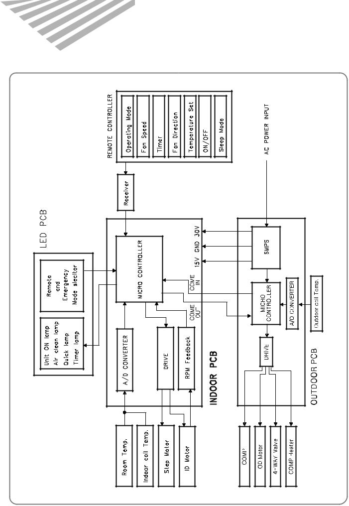
5. CONTROL BLOCK DIAGRAM
15
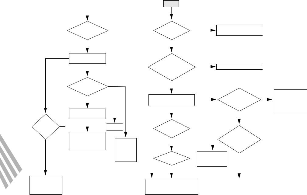
 6. TROUBLE SHOOTING
NO
Is the unit display mormal?
NO
YES
check the failure code according to the self-diagonostic
Trouble
|
|
|
|
|
|
|
|
|
|
|
|
|
|
|
|
|
|
|
Is the |
|
|
|
|
Is the power |
|
NO |
|
Check power supply mains |
|||||||||
unit display |
|
|
|
|
||||||||||||||
|
|
|
|
applied to the |
|
|
|
|
|
or interconnection wires |
||||||||
normal? |
|
|
|
|
|
|
|
|
|
|||||||||
|
|
|
|
unit |
|
|
|
|
|
|
|
|
|
|
||||
|
|
|
|
|
|
|
|
|
|
|
|
|
|
|
|
|||
|
|
|
|
|
YES |
|
|
|
|
|
|
|
|
|
|
|
|
|
YES |
|
|
|
|
|
|
|
|
|
|
|
|
|
|
|
|
|
|
|
|
|
|
|
|
|
|
|
|
|
|
|
|
|
|
|
|
|
Outdoor unit does |
|
|
|
|
Is the |
|
|
|
|
|
|
|
|
|
|
|||
not run? |
|
|
|
|
|
|
|
|
|
|
|
|
|
|
||||
|
|
|
|
power normal? |
NO |
|
|
|
|
|
||||||||
|
|
|
|
|
|
Check the wiring of indoor |
||||||||||||
|
|
|
|
|
||||||||||||||
YES |
|
|
|
|
check the voltage between |
|
|
|
|
|
||||||||
|
|
|
|
|
|
|
|
|
||||||||||
|
|
|
|
|
L & N of terminal |
|
|
|
|
|
|
|
|
|
|
|||
|
|
|
|
|
|
|
|
|
|
|
|
|
|
|
|
|||
|
|
|
|
|
|
block |
|
|
|
|
|
|
|
|
|
|
||
Does |
|
NO |
|
|
YES |
|
|
|
|
|
|
|
|
|
|
|
|
|
|
|
|
|
|
|
|
|
|
|
|
|
|
|
|
||||
the compressor run |
|
|
|
|
|
|
|
|
|
|
|
|
|
|
|
|||
|
|
|
|
|
|
|
|
|
|
|
|
|
|
|
|
|||
normally? |
|
|
|
|
|
|
|
|
|
|
|
|
Is the |
|
NO |
|||
|
|
|
|
|
|
|
|
|
|
|
|
|
||||||
|
|
|
|
|
|
|
|
|
|
|
|
|
|
|
||||
YES |
|
|
|
|
press the power ON/OFF |
|
|
|
|
|
switch position |
|
||||||
|
|
|
|
|
|
|
|
|
||||||||||
|
|
|
|
button on remote controller |
|
|
|
|
|
on switch pannel |
at |
|
|
|||||
|
|
NO |
|
|
YES |
|
|
|
|
|
|
|
"Remote" |
|
|
|
||
Indoor unit does |
|
|
|
|
|
|
|
|
|
|
|
|
||||||
|
|
|
|
|
|
|
|
|
|
|
|
|||||||
|
|
|
|
|
|
|
|
|
|
|
|
|
|
|||||
|
|
|
|
|
|
|
|
|
|
|
|
|
||||||
not run |
|
|
|
|
|
|
|
|
NO |
YES |
|
|
|
|
||||
|
|
|
|
|
|
|
|
|
|
|
||||||||
|
|
|
|
|
|
|
|
|
|
|
|
|
|
|
||||
YES |
|
Normal |
|
|
Does the |
|
|
|
|
|
|
|
|
|
|
|||
|
|
|
|
|
|
|
|
|
|
|
|
|
|
|||||
|
|
|
|
beeper beep two |
|
|
|
|
|
|
Does |
|
|
|
||||
|
|
|
|
|
|
|
|
|
|
|
|
|
|
|
||||
|
|
|
|
|
|
times? |
|
|
|
|
|
|
|
|
||||
Check the failure |
|
|
|
|
|
|
|
|
|
control PCB |
|
|
|
|||||
|
|
|
|
|
|
|
|
|
|
|
|
|
|
|
||||
code according to |
|
check the |
|
|
YES |
|
|
|
NO |
|
status LED repeat one |
|||||||
|
|
|
|
|
|
|
second "on and |
|
|
|
||||||||
the self diagnostic |
|
connecting |
|
|
|
|
|
|
|
|
|
|
|
|
|
|||
|
|
|
|
|
|
|
|
|
|
|
|
|
off"? |
|
|
|
||
|
|
|
point of |
|
|
|
|
|
|
|
|
|
|
|
|
|
||
|
|
|
|
|
|
|
|
|
|
|
|
|
|
|
|
|
|
|
|
|
|
magnetic |
NO |
|
Is the display |
|
• control PCB fault |
|
|
|
|
||||||
|
|
|
|
|
|
|
|
|
||||||||||
|
|
|
contactor |
|
|
|
|
|
|
|||||||||
|
|
|
|
|
|
• Micom or reset |
|
|
|
|
||||||||
|
|
|
|
|
|
|
|
|
|
|||||||||
|
|
|
|
|
|
all off? |
|
|
|
|
|
|||||||
|
|
|
|
|
|
|
IC fault |
YES |
|
|
|
|
||||||
|
|
|
|
|
|
|
|
|
|
|
|
|
|
|||||
|
|
|
|
|
|
YES |
|
|
|
|
|
|
|
|
|
|
|
|
|
|
|
|
|
|
|
|
|
|
|
|
|
|
|
|
|
||
|
|
|
|
• Check the connector on display |
|
|
|
|
|
|
|
|
|
|
||||
|
|
|
|
|
|
|
|
• Check the remote signal receiver |
||||||||||
|
|
|
|
PCB connected to control PCB |
|
|
• Check the connection between signal |
|||||||||||
|
|
|
|
• Check the display PCB itself |
|
|
|
|
|
receiver and control PCB |
||||||||
|
|
|
|
|
|
|
|
|
|
|
|
|
|
|
|
|
|
|
Place the switch position to the "Remote" and then Check it once more
16
Note 1)
1Neither indoor unit nor outdoor unit runs.
Check the following points first. (There are following case in normal operation)
a.Is the timer mode set the "timer ON".
b.Is the timer mode set the "timer-OFF" and the time had passed?
2Neither outdoor fan nor compressor runs while indoor fan runs.
Check following points first. (There are following cases in normal operation)
a.Is the temperature set point suitable?
b.Has the 3 minutes time guard for compressor operated?


 Self
Self
 -
-
 Diagnostic Function
1.Error Code I - ON LED blinking 3 times at Emergency Mode 1When the compressor do not run.
i)Check the voltage between L and Y of terminal block. (Indoor Unit, Outdoor Unit)
ii)Check connecting wire of indoor unit and outdoor unit. iii)Check relay RL1 on power P.C.B (outdoor PCB)
2Check fixing of indoor coil thermistor.
3Check the GAS LEAKAGE of the pipe.
2.Error Code 2 - ON LED blinking 1Check the sensor and its circuit.
2It occurs when sensor is open or short.
3.Error Code 3 – TIMER LED blinking 1Check the Indoor Fan Motor.
2Check the RPM feedback circuit.
3Indoor Fan Motor does not work for 5 seconds.
4.Error Code 4 – QUICK LED blinking
1Check the Communication system between Indoor unit and Outdoor unit.
17
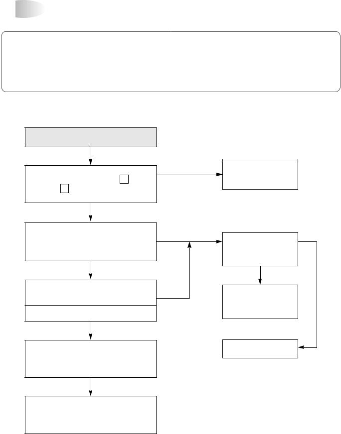


 Neither Indoor Unit nor Outdoor Unit Runs
Confirm following statement.
When the unit operate normally, Sometimes the outdoor unit and indoor unit cannot operate. 1Check the function select switch. Is it timer mode?
2The function select switch locate the sleep mode and is the setting time over? 3Is the setting mode DEHUMIDIFIER mode?
The power is applied to the unit
Check the voltge between L and Y of terminal block
Rating voltage
under 90%
Check the Breaker or Fuse
Rating voltage more than 90%
Check the indoor unit display is the display all off?
Yes
Press the ON/OFF switch of Remote Control
Is the indoor unit display all off?
Pull out the power plug and then insert the power plug
after 5 second
No |
No |
|
Self Diagnostic |
|
function is ON |
|
Yes |
No |
Check according to |
|
|
|
self Diagnostic function |
|
Control P.C.B defect |
Control P.C.B is normal Recheck from the beginning
18
 Loading...