

Page 1

TM
Using TargetPro
User’s Manual
Software documentation through 2.3
June 2004
Page 2

Copyright Notice
This software is copyrighted and licensed for use on one computer per copy.
Triton Elics International grants permission to the purchaser to make a limited
number of copies of the program for backup purposes. Additional reproduction of
the programs or this manual is a violation of the copyright law.
The licensee is bound by the terms and conditions set forth in the Software
License Agreement and Limited Warranty that accompanies this document.
Bathy Pro™, Isis
TriPort™, Q-MIPS™, VISTA™, TriCAS™, ROVFlight™, A-B™, and
Convert CD™, are trademarks of Triton Elics International, Inc.;
®
Isis
Sonar is a registered trademark of Triton Elics International, Inc.
The following are copyrights of their respective companies or organizations:
• WinRT Registry: BlueWater Systems
• HawkEye, Imagine 128: Number Nine Visual Technology Corp.
The following are trademarks and/or registered tradem arks of their respective
companies or organizations:
• EXB-8500, EXB-8505XLI, EXB-8500C, EXB-8205: EXABYTE
Corporation
• Windows, Windows NT, Windows 95, MS-DOS: Microsoft Corporation
• Pentium, MMX: Intel Corporation
• Adaptec AHA 1505 and AHA 2940: Adaptec, Inc.
• Klein 5000, Klein 2000, Klein 595: Klein Associates, Inc.
• DF-1000: EdgeTech
• Echoscan, Echotrac: Odom Hydrographic Systems, Inc.
• ADS-640, GSP-1086, EPC-9082: EPC Labs, Inc.
• Sentinel Scribe: Rainbow Technologies North America, Inc.
• mach64: ATI Technologies, Inc.
• HYPACK: Coastal Oceanographics, Inc.
• International Business Machines
• 1200C, DesignJet 650C: Hewlett-Packard
• 1086, 8300, 980x plotters: EPC
• TDU 1200, 850, 2000 plotters: Raytheon
• 195 (same as Dowty 195, Ultra 195 and Ultra 200): Waverley
• InstallShield: InstallShield Corporation
All other brand or product names mentioned in this manual are trademarks or
registered trademarks of their respective companies or organizations.
®
Sonar Pipeline, Delph Map®, Survey Office™, Hydro Suite™,
Page 3

p
Safety Precautions
When working with the overall system
1. Before handling components inside your computer system, exit all
applications and shut down the operating system in accordance with
procedures applicable to them.
2. Turn off the power to the computer and disconnect all cables that may be
feeding electrical power to the system you will be working on.
3. Wear a grounded, anti-static wrist-strap. This is especially important if
you are removing, replacing, or installing a printed circuit board of any
kind.
Failure to adhere to these and other safety precautions mentioned in the manual
could result in harm to property or personnel!
When working with magneto-optical cartridge disks
© 1991-2004 Triton Elics International, Inc. All rights reserved. Printed in the
Please adhere to the hardware and software
recautions mentioned below. In addition,
observe all safety precautions mentioned in this
manual.
• Please refer to the Appendix entitled “Mass Storage Options” for
important details covering the handling of M-O disks!
• Never boot your system with a writable M-O cartridge inserted
into the drive!
• Use magneto-optical media that has 512 bytes per sector, not
1024 bytes per sector, and use the AFDisk software utility to
format magneto-optical media. Never use Windows 95 to format
M-O media!
Triton Elics Internatonal
125 Westridge Drive
Watsonville, CA 95076
USA
U.S.A.
Page 4

SOFTWARE LICENSE AGREEMENT
By opening this package, you agree to be
bound by the terms of this Agreement,
which include the software license and the
limited warranty. This Agreement applies to
you and any subsequent licensee of this
software program. If you do not accept or
agree to the terms of this Agreement, do
not open this sealed package. Promptly
return the unopened package to TRITON
ELICS for a refund. However, no refund or
replacement will be given if the sealed
envelope containing the SOFTWARE
Sentinel and Manual has been opened or if
any of the components of the product
(including the software sentinel) are
missing. Grant of license for the software
product and full title and ownership of the
hardware product shall not transfer to the
Buyer until the purchase price, plus any
interest or fees resulting from late payments or pre-arranged terms, has been
received in full by the Seller.
1. GRANT OF LICENSE: TRITON
ELICS grants you the right to use the
enclosed TRITON ELICS software
product in the manner provided below.
YOU MAY:
• Use one copy of the TRITON ELICS
software products identified above on
a single computer.
• Make one (1) copy of the program in
machine-readable form solely for
backup purposes, provided that you
reproduce all proprietary notices.
• Transfer the SOFTWARE and user
documentation on a permanent basis
provided you retain no copies and the
recipient agrees to the terms of this
Agreement.
YOU MAY NOT:
1. Reverse engineer, decompile, modify or
disassemble the SOFTWARE except to the
extent such foregoing restriction is
expressly prohibited by applicable law.
Remove any proprietary notices, labels, or
marks on the program, documentation, or
program disk.
2. UPGRADES. SOFTWARE and
documentation upgrades are provided free
of charge for one year from the date of
shipment. If the SOFTWARE is an
upgrade, you may use or transfer the
SOFTWARE only in conjunction with
upgraded product. You may use that
upgraded product only in accordance with
this License.
3. COPYRIGHT. The SOFTWARE
(including any images, “applets,”
animations, video, audio, music, and text
incorporated into the SOFTWARE) is
owned by TRITON ELICS and is protected
by United States copyright laws and
international treaty provisions.
4. TECHNICAL SUPPORT. Technical
Support is available by phone, fax, modem,
Triton Elics bulletin board service or Internet free of charge during warranty period.
MARISAT charges are invoiced at cost
plus twenty percent.
5. EXPORT RESTRICTIONS. You agree
that neither you nor your customers
intends to or will, directly or indirectly,
export or transmit the SOFTWARE or
related documentation and technical data
to any country to which such export or
transmission is restricted by any applicable
U.S. regulation or statute, without the prior
written consent, if required, of the Bureau
of Export Administration of the U.S.
Department of Commerce, or such other
governmental entity as may have
jurisdiction over such export or
transmission.
Page 5

LIMITED WARRANTY
TRITON ELICS warrants that (a) the
SOFTWARE will perform substantially in
accordance with the accompanying written
materials for a period of one (1) year from
the date of shipment and (b) any hardware
accompanying the SOFTWARE will be free
from defects in materials and workmanship
under normal use and service for a period
of one (1) year from date of shipment.
CUSTOMER REMEDIES. TRITON
ELICS’s entire liability and your exclusive
remedy shall be, at TRITON ELICS’s
option, repair or replacement of the
SOFTWARE or hardware that does not
meet TRITON ELICS’s Limited Warranty.
Warranty service is F.O.B. TRITON
ELICS’s Watsonville facility. All shipping
and insurance costs are paid by buyer. Onsite Customer Service and Warranty
Repair (including travel hours,
transportation, lodging and meals) may be
provided by TRITON ELICS, at its own
discretion, to Buyer at cost plus twenty
percent. However, actual labor hours to
provide this service or repair will be free of
charge to Buyer. This Limited Warranty is
void if failure of the SOFTWARE or
hardware has resulted from accident,
abuse, or misapplication. Any replacement
SOFTWARE or hardware will be warranted
for the remainder of the original warranty
period or thirty (30) days, whichever is
longer.
NO OTHER WARRANTIES. Except for the
above express limited warranties, TRITON
ELICS makes no warranties, expressed,
implied, statutory, or in any communication
with you, and TRITON ELICS specifically
disclaims any implied warranty of
merchantability or fitness for a particular
purpose. TRITON ELICS does not warrant
that the operation of the program will be
uninterrupted or error free. Some
states/jurisdictions do not allow the
exclusion of implied warranties, so the
above exclusions may not apply to you.
This limited warranty gives you specific
legal rights. You may have others, which
vary from state/jurisdiction to
state/jurisdiction.
NO LIABILITY FOR CONSEQUENTIAL
DAMAGES. To the maximum extent
permitted by applicable law, in no event
shall TRITON ELICS be liable for any
damages whatsoever (including, without
limitation, damages for loss of business
profits, business interruption, loss of
business information, or any other
pecuniary loss) arising out of the use of or
inability to use this TRITON ELICS
product, even if TRITON ELICS has been
advised of the possibility of such damages.
Because some states/ jurisdictions do not
allow the exclusion or limitation of liability
for consequential or incidental damages,
the above limitation may not apply to you.
U.S. GOVERNMENT RESTRICTED
RIGHTS. The SOFTWARE and
documentation are provided with
RESTRICTED RIGHTS. Use, duplication,
or disclosure by the Government is subject
to restrictions as set forth in subparagraph
(c) (1) and (ii) of the Rights in Technical
Data and Computer Software clause at
DFARS 252.227-7013 or subparagraphs
(c) (1) and (2) of the Commercial Computer
Software—Restricted Rights at 48 CFR
52.227-19, as applicable. Manufacturer is
Triton Elics International, Inc., 125
Westridge Drive, Watsonville, CA 95076. If
you acquired this product in the United
States, this Agreement is governed by the
laws of California. If this product was
acquired outside the United States, then
local law may apply.
TRITON ELICS INTERNATIONAL
SOFTWARE LICENSE AGREEMENT
AND LIMITED WARRANTY
Page 6

Page 7

CHAPTER 1: OVERVIEW OF THE SOFTWARE
1.1 SOFTWARE ARCHITECTURE
1.1.1 What is TargetPro?
1.1.2 What File Types Can TargetPro Read?
1.1.3 What File Types Can TargetPro Write?
1.1.4 What Formats Are Best for Exporting?
1.2 SYSTEM REQUIREMENTS
1.3 SOFTWARE INSTALLATION
1.3.1 Installing a Hardware Dongle
1.3.2 Installing TargetPro
1.4 UPGRADING TO A NEW RELEASE OF SOFTWARE
CHAPTER 2: USING TARGETPRO
2.1 RUNNING TARGETPRO
2.2 OPENING A FILE
2.3 UNDERSTANDING TARGETPRO'S WINDOWS
2.3.1 Repositoning displayed child windows
2.4 ICONS ON THE TASKBAR
2.5 PAN AND DISPLAY ONLY PROPERTIES WINDOW
2.5.1 The Pan Window
2.5.2 The Display-Only Properties Window
CHAPTER 3: MEASURING A CONTACT
3.1 LENGTH
3.1.1 Length Adjust
3.1.2 Length Rotation
1
1
1
1
2
2
3
3
6
6
6
8
8
9
11
12
15
19
20
20
22
22
22
23
Page 8

3.1.3 Beam Width 24
3.1.4 Number of Pings
3.2 WIDTH
3.2.1 Width Adjust
3.2.2 Width Rotation
3.3 HEIGHT
3.4 GENERAL DIRECTIONS FOR OBJECT MENSURATION
3.4.1 Measure Distance
3.4.2 Measure Object Echo-Shadow (Tied)
3.4.3 Measure Object Length
3.4.4 Measure Object Echo
3.4.5 Measure Object Shadow
3.5 OBJECT DETECTION
3.5.1 Configuring Object Measurement
CHAPTER 4: OBJECT MODIFICATION AND CLASSIFICATION
4.1 THE ELECTRONIC LIGHT TABLE
4.1.1 The Histogram Window
4.1.2 The Statistics Area
4.1.3 The Rotation/Cropping Area
4.1.4 The Image Processing Area
4.1.5 The Color Processing Area
4.1.6 The Audit Trail Area
4.1.7 Apply to Large Image, Undu Large Image and Close
4.1.8 Annotate
4.2 CLASSIFYING A TARGET
4.3 GEOCORRECTING A CONTACT OR TARGET IMAGE
4.4 SETTING AND VIEWING TARGET IDENTIFICATION
24
25
25
25
26
27
28
28
29
30
30
31
32
33
33
34
35
35
36
38
39
39
40
40
43
47
Page 9

4.4.1 Setting a Contact Number 47
CHAPTER 5: TARGETPRO MENU
5.1 THE FILE MENU
5.2 THE EDIT MENU
5.3 THE TOOLS MENU
5.3.1 Configuring to Display Data
5.3.2 RAMP Support
5.3.3 Inspecting TAG 270 Information
5.4 THE WINDOW MENU
5.5 THE VIEW MENU
5.6 THE HELP MENU
49
49
54
54
55
59
60
63
63
64
CHAPTER 6: TROUBLESHOOTING
65
ADDENDUM: The Effect of Speed Correction on Images from TargetPro and
Target
68
Page 10

June 2004 TargetPro™ User's Manual
Chapter 1: Overview of the Software
1.1 Software Architecture
1.1.1 What is TargetPro?
TargetPro is a software module included with Isis sonar from Triton Elics
International, Inc. TargetPro is also sold as a separate, standalone utility.
If you have the Isis Sonar software (also from Triton Elics International), you
can use TargetPro to take snapshots of selective areas of your data imagery
that may be of interest to you. When TargetPro takes a snapshot of an
image, TargetPro also logs the quantitative data (geocoding, contact
mensuration) associated with the original data imagery from which the
image came.
You can then save these small images as files independent of the original
data imagery. Furthermore, you can then recall the image in Isis without
having to play back the entire data imagery that contained the selected
image – or you can have Isis play back the image in the larger context of
your data imagery, in case youwant to see the area surrounding the
selected image.
Even if you don’t have Isis, you can still use TargetPro to view and modify a
wide variety of images, including images that were created by someone else
who did have Isis. Finally, you can run TargetPro from DelphMap as a utility
for viewing and modifying files known to TargetPro.
1.1.2 What File Types Can TargetPro Read?
TargetPro can open (read) these file types:
• Contact (TEI proprietary *.CON files)
• Target (TEI proprietary *.TGT files)
• ESC image (*.TIF or *.TIFF files, with Tag 270 information in them)
• Pulse Code Modulation image (*.PCM, which are compressed ESC
image files)
• Joint Photographic Experts Group (*.JPEG and *.JPG files)
• Compuserve Portable Network Graphic (*.PNG files)
Chapter 1: Overview of the Software 1
Page 11

June 2004 TargetPro™ User's Manual
• Microsoft Windows Paint (*.PCX files, which support color as well as
black and white)
• Microsoft Windows Bitmap (*.BMP files)
• Microsoft Windows Metafile (*.WMF files)
• Enhanced Metafile (*.EMF files)
1.1.3 What File Types Can TargetPro Write?
TargetPro can write (save) files into many file fortmats:
LEAD (1,8,24); JPEG (8,12,16,24); CALS 1-bit; Cserve PNG (1,8,24);
DICOM DIC (8,16,24); FAX (raw); EPS; EXIF; FPX (8,24); GEM 1-bit; GIF
(1-8); IOCA; MODCA (Raw IOCA); Mac PICT (1,4,8,24); MacPaint 1-bit; MS
FAX (AWD); MS Paint; OS/2 BMP (1,4,8,24); PCX (1,4,8,24); PSD (1,8,24);
SUN Ras (1,4,8,24,32); TGA 8,16,24,32); TIF (1-8,12,16,24,32); Win BMP
(1,4,8,16,24,32); Winfax; WMF (8,24); EMF (8,24); WPG (1,4,8); Win lco
(1,4,8); Win Cur 1-bit.
In the preceding list, the numbers in parentheses are the number of bits
supported for the named formats. Note, however, that TargetPro cannot
save PCM images as PCM images; that format can only be saved in
TargetPro as a non-PCM format file, such as TIFF.
1.1.4 What Formats Are Best for Exporting?
If you’re going to export an image from TargetPro and then use that image
in another application, you may want to save your image in a format that
offers the most support in the application that will receive the imported
image. At present, the best formats for saving TargetPro images to be used
in other applications are (in alphabetical order):
• BMP (24-bit)
• GIF (8-bit, 89a non-interlaced)
• JPG (24-bit progressive)
• PCX (24-bit, version5)
• PSD (24-bit PhotoShop file)
• TIF (24-bit)
The 24-bit formats are the only ones to support exporting the image in color.
All formats other than 24-bit will be in gray scale.
Note: The 24-bit TIF and BMP file formats are lossless. This is desirable,
since lossless formats retain all information even if you later compress or
enlarge the image.
Chapter 1: Overview of the Software 2
Page 12

June 2004 TargetPro™ User's Manual
1.2 System Requirements
You need the following:
• A Pentium-class personal computer running Windows NT,
Windows 2000, or Windows XP.
• At least 32 MB of RAM.
• A software license from Triton Elics International to use the product. (The
license comes with TargetPro when you buy it.)
• A hardware dongle that has been programmed to recognize TargetPro.
• A computer monitor capable of displaying true 24-bit color images
(potentially 16,777,216 colors.) You could use a monitor that supports
fewer colors, but the results won’t be as good as they would be on a
monitor that can support 24-bit color images. Also, so that you can see
all of the application’s working area, your monitor must be set to at least:
1280 X 1024 pixels if you are using large fonts, or
1152 X 864 pixels if you are using small fonts
Before you can use TargetPro, you must install the TargetPro software using
InstallShield, and you must attach a properly configured dongle to your computer
to access the program.
1.3 Software Installation
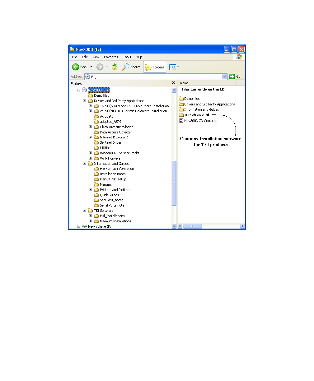
Typical software installation CD will contain folders like the ones depicted in the
Windows Explorer layout. (See the figure, “Typical listing of TEI software
installation folders’.)
Chapter 1: Overview of the Software 3
Page 13
June 2004 TargetPro™ User's Manual
Figure 1. Typical listing of TEI software installation folders.
TEI software is compatible with Windows NT 4.0, Windows 2000, and Windows
XP. The following notes will help you achieve a smooth installation of the
software.
• Please exit from all other applications before running any of the
installation programs.
• You will not be able to complete the installation on an NT4.0 or
Windows 2000 system if you do not have administrator’s rights. All Isis
“black boxes” ship with a user name Isis. In this case the Isis user
name has administrator’s rights and does not require a password.
Chapter 1: Overview of the Software 4
Page 14

June 2004 TargetPro™ User's Manual
• Each application is installed by browsing to the appropriate folder (for
example, Isis5.50 Install) on the CD and double-clicking on the
SETUP.EXE file found in that folder.
• TEI recommends that if you have more than one hard drive, you install
the software on the second (usually the D:) drive, using the default
folder names on the CD. You will be given the option to select any drive
during the setup process, select the Custom option and change the
drive letter.
• The first installation on an NT4.0 system requires a re-boot during the
installation; however, this only occurs for the first installation. Under
Windows 2000 and Windows XP, no rebooting is necessary
installation process. However, you
must reboot the system after
installing under Windows NT 4.0.
• For each application, a number of sample data files can be optionally
installed. These files will reside in a subfolder called Demo Files within
each application’s main folder. These special files can be played back
or processed by the relevant TEI applications without a TEI sentinel
being installed. If no sentinel (dongle) is attached, a message displays,
indicating either that a sentinel was not found or that the sentinel is
damaged. However, you can still play back the sample files that come
from the CD.
• In order to run the software in acquisition mode, or to play back or
process other files, you will need a TEI sentinel attached to the LPT1
printer port. Contact TEI if you need a sentinel.
• If the operating system is Windows NT 4.0 or Windows 2000, you will
need to install a sentinel driver. The driver is included on the CD in the
Sentinel folder; a text file, with installation instructions, is in that folder.
The driver is
not required under Windows 95 or Windows 98.
• In the case of Windows NT 4.0, Service Pack 5 (or higher) needs to be
installed. Service Pack 5 is on the CD.
• The TEI manuals that are installed with the software are in Adobe
Acrobat PDF format. Acrobat Reader software (required to read the
PDF files) is also on the CD.
• The CD has a number of other folders containing drivers and
applications that could be required; each folder has a text file with more
information.
• To remove the software, use the Add/Remove Programs utility in the
Windows Control Panel collection of utilities.
• The installations make two changes which are not restored when the
programs are removed using Add/Remove Programs. They are:
during the
Chapter 1: Overview of the Software 5
Page 15

June 2004 TargetPro™ User's Manual
The addition of a folder called [TEIdlls] in the Windows, Win95 or
WINNT folder, and
a modification to the PATH environment variable which adds the
[‘TEIdlls] folder to the PATH. The [TEIdlls] folder can be safely
deleted after all TEI software has been removed.
1.3.1 Installing a Hardware Dongle
A hardware dongle comes with TargetPro. The dongle permits TargetPro to
run after the software is installed.
To install the dongle, plug in the male end of the dongle to the female end of
a serial port on your computer.
1.3.2 Installing TargetPro
Triton Elics Int ships TargetPro with a utility used to install the product for
you. From the distribution medium made available to you from Triton Elics
Int, find the file called
install utility InstallShield. Respond to any InstallShield prompts, as may be
needed; let InstallShield guide you in the installation. When InstallShield
finished, the installation is complete, and TargetPro is ready to run.
setup.exe and double-click it. The system runs the
1.4 Upgrading to New Releases of Software
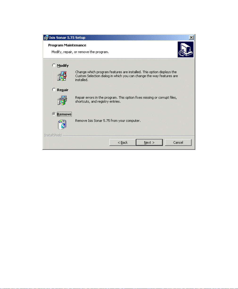
If you already have a version of the software that you wish to upgrade on your
system you will see a dialog box inviting you to modify, repair, or remove the
software you intend to install. See the figure, ‘Modify, Repair, Remove choices
during installation’ for an example of this kind of dialog box.
Chapter 1: Overview of the Software 6
Page 16
June 2004 TargetPro™ User's Manual
Figure 2. Modify, Repair, Remove choices during installation.
You will need to remove the old version of the software before you will be
permitted to install the new version. To do so, enable the Remove button in the
dialog box and click Next. You can then install the new version by rerunning
setup.exe As noted above, some items are deliberately not removed during the
uninstall process; doing so can cause problems. If necessary, manually delete
the \TEIdlls folder, but only do this if you are going to re-install all TEI
applications.
Important Note: The Windows Installer will fail to uninstall the software if
the operating system has been upgraded from (for example) Windows 98 to
Windows 2000 after the TEI applications were installed. If you want to
upgrade your operating system, uninstall the TEI programs first, and then
re-install the TEI programs after the upgrade.
Chapter 1: Overview of the Software 7
Page 17

June 2004 TargetPro™ User's Manual
Chapter 2: Using TargetPro
If you’ve installed the TargetPro software and have it running, you can use it to
open CON (contact) or TGT (target) fields, enhance them, and save the changed
files. This chapter explains how to do that.
You can then save these small images as files independent of the original data
imagery. You can then recall the image in Isis without having to playback the
entire data imagery that contained the selected image – or you can have Isis
playback the image in the larger context of your data imagery, in case you want
to see the area surrounding the selected image.
2.1 Running TargetPro
You can run TargetPro in a number of ways, shown next. Choose a convenient
method.
To run TargetPro, double-click on the TargetPro icon in the Triton group
(Microsoft Windows), or
• From Isis, configure for TargetPro availability (Tools → Target Setup…),
and then double-click the left trackball button while imagery is scrolling in an
Isis waterfall window to put a contact in the TargetPro working window.
TargetPro runs and displays its initial screen (Figure 3). Moreover, if you have
run TargetPro before, TargetPro remember the overall size and position of the
application window as it was when you last used it.
Chapter 2: Using TargetPro 8
Page 18
June 2004 TargetPro™ User's Manual
Figure 3. Initial screen (empty) after first running TargetPro.
Because you have not yet opened a file for TargetPro to display, the Main
Working Area of the initial TargetPro screen, as well as any smaller child
windows that may be present, are empty of information. See ‘Understanding
TargetPro’s Windows’ for an explanation of the various parts of the application’s
overall window.
2.2 Opening a File
As noted earlier, you can work with any file types in TargetPro:
• Contact (TEI proprietary *.CON files)
• Target (TEI proprietary *.TGT files)
• ESC Image (*.TIF or *.TIFF files, with Tag 270 information in them)
Chapter 2: Using TargetPro 9
Page 19

June 2004 TargetPro™ User's Manual
• PCM Image (*.PCM, which are compressed ESC image files)
• Joint Photographic Experts Group (*.JPEG and *.JPG files)
• CompuServe Portable Network Graphic (*.PNG files)
• Microsoft Windows Paint (*.PCX files, which support color as well as
black and white)
• Microsoft Windows Bitmap (*.BMP files)
• Microsoft Windows Metafile (*.WMF files)
• Enhanced Metafile (*.EMF files)
Those are the only file types that can be opened in TargetPro. If your contact
(CON) or target (TGT) files have been saved as digitized lines and/or polygons,
then TargetPro will display them that way.
To open a file TargetPro can recognize, do any of the following:
• From TargetPro’s main menu, choose File→Open,
• Press <CTRL>+<O>,
• Press [Insert],
or
or
or
• On the taskbar click the Open icon:
Any of those actions displays a standard Windows-based dialog box where you
can specify a file to pen. A typical file opened in TargetPro looks like the sample
shown in Figure 4.
Chapter 2: Using TargetPro 10
Page 20

June 2004 TargetPro™ User's Manual
Figure 4. Typical file opened in TargetPro
After a file has been opened, the original list of menu items (File, Edit, Tools,
View and Help) expands to include two additional menu choices: Object and
Window.
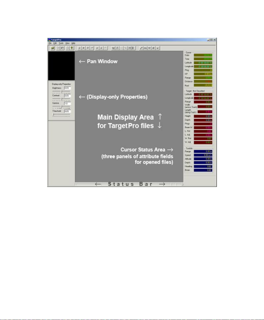
2.3 Understanding TargetPro’s Windows
Initially TargetPro displays these windows and working areas:
• the Pan window
• the Display-Only Properties window
• the main display area for viewing opened files
Chapter 2: Using TargetPro 11
Page 21

June 2004 TargetPro™ User's Manual
• the Cursor Status window
• taskbar icons
• Status Bar
In the taskbar area, all icons except for the Open icon and the About icon are
grayed out and unavailable until you open a file in TargetPro. All icons are
explained in “Icons on the Taskbar”.
If you double-click on any of the windows (except for the main display area), the
system displays the windows’ title bars and reveals their identities (Figure 3).
Note that the windows still lack information in them because you have not yet
opened a file in TargetPro. The two windows (Pan and Display-Only Properties
windows) are explained later on.
The Status Bar, where on-going and current status is displayed, is a narrow strip
at the bottom of the TargetPro window (Figure 3).
2.3.1 Repositioning displayed child windows
To reposition a displayed child window, double-click in the child window to
expose the windows title bar. Then, click in the title bar and drag the
window to the new position.
To return an undocked window to its original position, double-click in the
child window and the window moves back to its initial position.
All windows except the Main Display Area are child windows of TargetPro.
You can close or open the child windows from the View menu listed above
the Taskbar icons. The Main Display Area is not redockable (movable).
The individual windows are:
Pan Window. The black window near the upper left corner is a thumbnail
window for the currently active, opened TargetPro image, if any is present.
This window is known as the Pan Window. See ‘Pan and Display-Only
Properties Windows’ for more detailed information on this window.
Display-Only Properties Window. This child window contains four
independent controls for adjusting an image’s brightness, contrast, gamma,
Chapter 2: Using TargetPro 12
Page 22
June 2004 TargetPro™ User's Manual
and threshold. See ‘Pan and Display-Only Properties Windows’ for more
detailed information on this window.
Cursor Status Area. The rightmost area contains three panels of attribute
fields that may show information when you open a file in TargetPro,
depending on the type of navigation data and other attributes that may have
been present in the opened file prior to opening. Within the Cursor Status
Area, information is arranged in three panels:
• Cursor Panel
• Target-Debris Panel (or Target – Not Classified, if your opened file is not
a target or contact type of file)
• Towfish Panel
The fields in these three groups are explained in Table 1.
Status Bar. When you open a TargetPro file and that file has the active
focus, text identifying key properties of that file (such as file name, number
of pixels in the x and y axes, file size, zoom level, etc.) appear here.
TABLE 1. Table One: Fields in the Cursor Status window
Parent Panel
for Attributes
Cursor
Chapter 2: Using TargetPro 13
Attribute Field Name and Explanation
Date: This is the Julian date the data were recorded.
Time: This is the time (hh:mm:ss) the data were recorded.
Latitude: These are the degrees north or south of the equator
as measured from the point of the trackball pointer when the
contact was made. The heading of this field changes to
Northings if the data were recorded that way.
Longitude: These are the degrees east or west of the meridian
as measured from the point of the trackball pointer when the
contact was made. The heading of this field changes to
Eastings if the data were recorded that way.
Ping: The nth consecutive ping (shot) of the recorded data at
the point where the trackball pointer was placed when the
Target contact was created.
KP: Kilometers of Pipe or Kilometer Posting. Measure of
distance along a pipe or pipeline route.
Range: This is the range from the towfish to the current point,
either the cursor or the object being measured.
Page 23
June 2004 TargetPro™ User's Manual
Distance: This is the distance between the end-points of the
rubber-band line drawn from one contact to another.
Pixel: This displays the x (x-axis coordinate), y (y-axis
coordinate), and z data (intensity) of any pixel in the displayed
image.
Target –
Debris
(or Target – Not
Classified for
non-contact
files)
Latitude: Degrees north or south of the equator. This changes
to Northings if the data were recorded that way
Longitude: Degrees east or west of the meridian. This changes
to Eastings if the data were recorded that way.
Range: This is the range from the towfish to the current point,
either the cursor or the object being measured.
Width: Across-track distance of mensuration.
Length: Along-track distance of mensuration.
Height: Height is how far an object stands above the seabed.
Height computation uses the length (width in across-track) of
the shadow, distance of the object from the towfish, and the
towfish altitude.
Depth: This is the vertical distance the target is from the sea
surface.
Pings: Number of pings traversed by a drawn line. Also see
‘Number of Pings’.
Beam W.: Width of the beam at a specific range distance. This
parameter is updated with any length measurements. Also see
‘Beam Width’.
Target –
Debris
(or Target – Not
Classified for
non-contact
files,
cont’d)
L.Rot. (Length Rotation) Rotation angle of the length line
relative to a horizontal line. Angle is computed from a
horizontal line. Also see ‘Length Rotation’ on page 28.
L.Adj. (Length Adjust) is the difference between the length of a
line and its along-track length. In the case of a slanted line,
length is derived from the vertical component of the line, and
the L.Adj. measures the difference between the length of the
line and the along-track length. Also see ‘Length Adjust’.
W.Adj. (Width Adjust) is the difference between the length of
the line and the across-track width. Also see ‘Width Adjust’.
W.Rot. (Width Rotation) Rotation angle of the width line
relative to a horizontal line.
Chapter 2: Using TargetPro 14
Page 24
June 2004 TargetPro™ User's Manual
Towfish
Range: This is the range from the towfish to the current point,
either the cursor or the object being measured.
Speed: This is the towfish’s speed.
Altitude: This is the vertical distance the towfish is from the
seafloor at nadir.
Depth: This is the vertical distance the towfish is from the sea
surface.
Note: altitude + depth = total water column depth
Heading: With respect to standard compass bearings, this is
the direction, in decimal degrees, in which the towfish is
pointed.
Beam: This is the horizontal beam angle of the sidescan sonar.
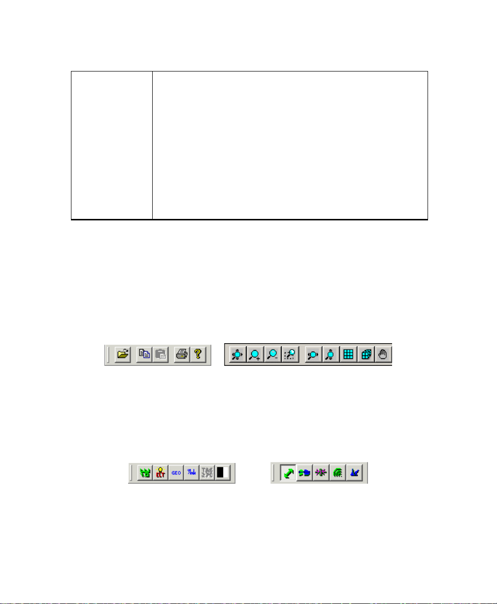
2.4 Icons on the Taskbar
Immediately underneath the menu list is the TargetPro taskbar of icons. They
are shown in Figures 5 and 6. Several of the icons have to do with operating the
cursor, or trackball pointer in the program. Additional icons are associated with
the Measurement Tool and the Zoom Tool. Tool Tips are attached to each icon,
and each icon has a menu equivalent in the Tools menu.
Group One Group Two
Standard Windows Zoom and Pan Windows
Figure 5. Groups One and Two of TargetPro’s taskbar icons
Group Three Group Four
Image Management Measurement Pointer Types
Figure 6. Groups Three and Four of TargetPro’s taskbar icons.
Chapter 2: Using TargetPro 15
Page 25
June 2004 TargetPro™ User's Manual
For space reasons, the icons appear in this book in two rows. In the TargetPro
program, the icons are laid out in a single row. Most icons are grayed out until a
contact image is opened. All icons become visible when an image is opened and
as long as the Cursor Tool icon remains clicked. (The Paste icon will be grayed
out if there is nothing in the Windows Clipboard.) All choices within an icon
group are mutually exclusive; you can perform only one function at a time from a
group. Icons in Groups Two, Three and Four are unique to TargetPro. All the
icons are explained in the next few tables.
TABLE 2. Group Two: Standard Icons
Open icon. Click this to get a dialog box where you can specify a file to
open from TargetPro’s combo box. This icon is equivalent to choosing
File →Open from the main menu. The equivalent keyboard shortcut is
<CTRL>+<O>
Copy icon. Click this to copy the currently displayed target contact to the
Windows Clipboard. Menu equivalent: Edit →Copy. The equivalent key-
board shortcut is <CTRL>+<C>
Paste icon. Click this to get a dialog box where you can choose a type of
image to paste: ESC (Electronic Still Camera images as TIFF files having
the Tag 270 attribute), Generic Image, Contact File, or Target. Menu
equivalent: Edit →Paste. The equivalent keyboard shortcut is
<CTRL>+<V>
Print icon. Click this to get the standard Windows Print dialog box from
which you can print the currently displayed image. Menu equivalent:
File→Print. The equivalent keyboard shortcut is <CTRL>+<P>
About icon. Click this to see the About TargetPro information box. The
box reveals the program’s name, version number, date compiled,
Copyright date, and the icon associated with the program. There is no
equivalent keyboard shortcut.
Chapter 2: Using TargetPro 16
Page 26

June 2004 TargetPro™ User's Manual
TABLE 3. Group Three: Zoom and Pan Icons
Fit to Window. Fills the current display area, out to the nearest border,
with the contents of the image. The aspect ratio of the image is
preserved.
Zoom In. Enlarges the size of the displayed image by some amount.
The aspect ratio of the image is preserved.
Zoom Out. Reduces the size of the displayed image by some amount.
The aspect ratio of the image is preserved.
Zoom Rectangle. Allows you to drag your pointer across and up (or
down) the image to define a rectangle which becomes an area to frame
the displayed image
Fit Width. The image enlarges until the left and right edges of the image
have reached the left and right edges of the current display area. The
aspect ratio of the image is preserved.
Fit Height. When this icon is clicked, the image enlarges until the top
and bottom edges of the image have reached the top and bottom edges
of the current display area. There is no menu equivalent. The aspect
ratio of the image is preserved.
Linear Zoom. Creates a new image by averaging adjacent pixels.
Cubic Zoom. Minimizes the raggedness by using interpolation which
estimates how the “missing pixels” should appear. Then fills them with
the appropriate color
Pan Image. Your pointer changes to the shape of a red hand. You can
move a contact image around in the main display area to visually
observe different areas of interest in the image. The image is not
zoomed. The menu equivalent is Tools →Pan Image.
Chapter 2: Using TargetPro 17
Page 27

June 2004 TargetPro™ User's Manual
TABLE 4. Group Four: Image Management Icons
Measurement Tool. When selected, this icon enables five more icons
specific to mensuration when you select Measurement Tool (see
Table 4, ‘Group Four: Measurement Pointer Icons,’ on page 24.)
Display ELT. Summons the Electronic Light Table dialog box where you
can modify (enhance) several aspects of the existing contact image.
Menu equivalent: Tools →ELT (see ‘The Electronic Light Table’ on page
37.
Geometrically Correct Image. This icon launches the Geometrical
Correction Parameters dialog box, a tool for correcting distortion caused
by the compression of images during a recording session. Menu
equivalent: Tools Geocorrect (see ‘Geocorrecting a Contact or Target
Image’).
Annotate. Clicking this icon (or choosing Tools Annotate from the main
menu) summons a dialog box where you can inspect text that may have
been typed at an earlier time. You can modify this text or type new text.
If you click OK, any text that may be present here will then be associated
as an annotation to the currently displayed con file. The annotation will
be available for the currently displayed con file whenever that file is
opened. The keyboard shortcut is <F2>.
TAG270. If you opened a TIFF file containing Tag 270 information, this
icon becomes available. Clicking it causes the TAG270 Information
dialog box to be displayed. This icon has no menu equivalent. For
images not containing Tag 270 TIFF information, this icon is grayed out
and unavailable
Reverse Palette. Inverts the order of the displayed colors (for example,
black becomes white and white becomes black, etc.)
Object Detection. Clicking this icon summons the Object Detection
dialog, where TargetPro will automatically detect objects using variations
in amplitude of the image.
Chapter 2: Using TargetPro 18
Page 28

June 2004 TargetPro™ User's Manual
TABLE 5. Group Five: Measurement Pointer Icons
Note: The Measurement Tool (see Table 3, ‘Group Three: Image Management
Icons’) must first be selected before you can choose a measurement type. Rightclicking in imagery reveals a menu of equivalents.
Measure Distance: When this measurement pointer type is selected,
you can draw a straight line in any direction across the image. The
length of that line is reported as a distance value in the Cursor Status
Panel
Object Echo-Shadow: Use this measurement pointer tool to find the
height of an object in the imagery.
Object Length: Use this measurement pointer tool to find the along-
track distance of an object in the imagery.
Object Echo: Use this measurement pointer tool to find the across-
track distance of an object in the imagery.
Object Shadow: Use this measurement pointer tool to find the
across-track distance of an object’s shadow in the imagery.
2.5 Pan and Display Only Properties Windows
The two leftmost child windows, the Pan window and the Display-Only Properties
window, control image panning and three basic image properties. You can move
these windows around and reposition them (“redocking” windows) to suit your
own needs – even outside the borders of the TargetPro application window, if
you so desire. See ‘Understanding TargetPro’s Windows’ for the repositioning
methods and sample screens.
Chapter 2: Using TargetPro 19
Page 29

June 2004 TargetPro™ User's Manual
2.5.1 The Pan Window
The small, redockable Pan window acts as a visual aid to show you what
part of the total image is being displayed in the larger main display window,
rather like being able to see the forest from the trees, as the saying goes.
Figure 3 shows an example of this. Initially, the area indicated in the Pan
window is the same as the area covered in the main display window, and
the Pan window has a thin red line around the Pan window. This is the
default for a newly opened TargetPro file.
To use the TargetPro Pan window, follow these steps:
1. Select the Pan Image tool. The trackball’s or mouse’s pointer changes
to the same shape as the icon (a hand)
2. Move the pointer over the image in the main display area.
3. Click and drag the image in a desired direction.
As you drag, the rectangle surrounding the Pan window moves to show
which parts of the image in the main display are actively displayed. Notice
that the size of the rectangle adjusts to reflect the change. The overall size
of the image in the Pan window remains the same, thereby showing the
contact’s context.
2.5.2 The Display-Only Properties Window
This redockable child window contains three independent controls for
adjusting an image’s brightness, contrast and gamma. These are controls
of convenience, not precision. If you slide any of these slider bars, you will
notice that there are no numerical values displayed. These slider bars are
there so that you can make some quick, temporary and rough changes to
the images to get an idea what the effects might be like. For precise
changes to your imagery, use the Electronic Light Table function (see ‘The
Electronic Light Table’).
• Brightness, which affects the brightness of the image. Sliding the
brightness indicator to the right along the bar increases brightness;
sliding it to the left decreases brightness. The midpoint position
represents no applied intensity, which is the default.
• Contrast, which affects the dynamic range of the dark and light parts of
an image. Sliding the contrast indicator to the right along the bar
increases the image’s contrast. This results in a larger standard
Chapter 2: Using TargetPro 20
Page 30

June 2004 TargetPro™ User's Manual
deviation between the dark and light parts of an image. Sliding the
contrast indicator to the left along the bar decreases the image’s
contrast. This results in a smaller standard deviation between dark and
light parts of an image. The midpoint position represents no applied
contrast, which is the default.
• Gamma, which is a way of logarithmically compensating for low intensity
pixels that may be present in some images. Only low intensity pixels
are affected. Sliding the bar to the right increases the gamma index for
the image; sliding it to the left decreases it. The midpoint of the scale
represents no gamma applied.
Threshold, which acts upon the current contrast setting, can be used to
adjust the level of contrast stretching. When the slider control is positioned
at the left side of the bar, no thresholding is applied. Maximum thresholding
of the contrast is applied when the slider control is at the far right side of the
bar.
Chapter 2: Using TargetPro 21
Page 31

June 2004 TargetPro™ User's Manual
Chapter 3: Measuring a Contact
You can measure, or mensurate, any part of a displayed contact. After a contact
is mensurated, you can read the values for measured distance in the Target –
Debris fields of the Cursor Status window.
Mensuration occurs in three dimensions: length, width and height. You use
TargetPro’s Measurement Tool icon on the toolbar (shown here at the side of the
page) to get a contact’s measurements. Additional, related icons become
available upon activating this icon.
3.1 Length
Length is the along-track ground distance between the
start and end points of a line drawn by the user, taking
into account the beam’s width (see ‘Beam Width’).
Four secondary aspects of contact measurement are associated with Length:
Length Adjust, Length Rotation, Beam Width and Number of Pings. Fields for
these secondary aspects are found in TargetPro’s Cursor Status Area.
The Measurement Tool’s Object Length function (shown
here at the side of the page) is used to draw the line.
3.1.1 Length Adjust
(L Adj.) is the difference between the length of the line and the along-track
length. Figure 7 shows the relationships.
Chapter 3: Measuring a Contact 22
Page 32

June 2004 TargetPro™ User's Manual
Figure 7. Length Adjust concept and relationship to length and line
3.1.2 Length Rotation
(L Rot.) is the rotation angle of the drawn line. This angle is relative to the
horizontal line of the across-track vector. As indicated in Figure 8, angles
above the imaginary horizontal line are positive (>0); angles below the
imaginary horizontal line are negative (<0). The angle’s value is not
computed in the bitmap space but is based on real ground distances (that is,
the angle value takes into account that the scale is different in the alongtrack and across-track direction).
Chapter 3: Measuring a Contact 23
Page 33

June 2004 TargetPro™ User's Manual
Figure 8. Length Rotation angle sign conventions
3.1.3 Beam Width
(Beam W.) is the width of the beam in ground distance at a specific
range. Figure 9 demonstrates the concept.
Figure 9. Top view of four beam widths at four arbitrary ranges
3.1.4 Number of Pings
(Pings) Number of pings in the Cursor Status Area) traversed by the drawn
line.
Chapter 3: Measuring a Contact 24
Page 34

June 2004 TargetPro™ User's Manual
3.2 Width
Width is the across-track ground distance between the start
and end points of a drawn line. The Measurement Tool’s
Object Echo function (shown here at the side of the page is
Two secondary aspects of contact measurement are associated with Width:
Width Adjust and Width Rotation. Fields for these secondary aspects are
found in TargetPro’s Cursor Status Area.
3.2.1 Width Adjust
(W. Adj) is the difference between the length of the line and the across-track
distance (see below).
sued to draw the line.
Figure 10. Width Adjust derived from line distance and width
3.2.2 Width Rotation
(W.Rot.) is the rotation angle of the width line relative to a horizontal line.
Chapter 3: Measuring a Contact 25
Page 35

June 2004 TargetPro™ User's Manual
3.3 Height
Height is the magnitude to which an object stands above
the seabed. The Measurement Tool’s Object Shadow
function (shown here at the side of the page) is used to
Such objects cast an acoustic shadow on the side facing away from the towfish.
The length (or across-track width) of this shadow can be used in combination
with the fish altitude and horizontal distance from the fish to derive height
information.
The computational method assumes that the target is a thin, vertical object. As
such, the height formula is:
draw a line in imagery.
Height = FishAlt * L1/(L1 + L2)
Figure 11. Height from fish altitude, shadow lengths and distances
Note: The shadow occurs on the left of the contact for a port channel and on the
right of the contact for a starboard channel.
A negative range in the Cursor Status window indicates a port-side i mage, and a
positive range indicates a starboard-side image. A separation of the shadow
from the contact indicates that the contact is moored (that is, not in contact with
the seabed).
Chapter 3: Measuring a Contact 26
Page 36

June 2004 TargetPro™ User's Manual
3.4 General Directions for Object Mensuration
1. Activate Measurement Tool (choose Tools→Measure from the main
menu or the Measurement Tool icon, pictured on Table 4, ‘Group Four:
Image Management Icons,’ from the taskbar of icons).
2. The system displays a set of mensuration icons on the taskbar, and your
pointer changes to a canted arrow with tick marks (hash marks) under it.
3. Choose a mensuration method either by selecting one of the
mensuration icons or by right-clicking in your imagery to reveal a menu
of mensuration choices as shown in Figure 12. (The left-to-right lineup of
mensuration icons corresponds to the top-to-bottom choices in the
submenu.)
4. Draw your line by traversing the desired distance or area to be
measured, releasing your pointer, and finally left-clicking again to
complete the line.
→
FIGURE 12. Measurement Tool menu choices (from Tools
A line representing the type of mensuration technique you performed is drawn in
your imagery. Reading from left to right in the set of mensuration icons, the color
schemes for each type of mensuration line is as follows:
• Measure Distance: red
• Object Echo-Shadow: green
• Object Length: purple (magenta)
• Object Echo: green
• Object Shadow: cyan
At the same time that your measured line appears in the imagery, the
metrics for that line appear in a related field of TargetPro’s Cursor panel.
The different ways of mensurating with the Measurement Tool are explained
next.
Chapter 3: Measuring a Contact 27
Measure)
Page 37

June 2004 TargetPro™ User's Manual
3.4.1 Measure Distance
Use this method to mensurate a distance in your imagery. A distance can
cover any part or all of your imagery in any direction and does not have to
start and stop at the boundaries of objects.
To measure distance in your imagery, do the following:
1. Activate the Measurement Tool (choose Tools→ Measure from the main
menu or the Measurement Tool icon from the taskbar of icons).
2. Choose the Measure Distance method of mensuration.
3. Starting from some visual point of interest, hold down the mouse or
trackball button and drag in some direction.
4. As you do, a red line is drawn.
5. Stop dragging and left-click the mouse or trackball again.
6. A red line is completed. The red line is completed. The length of this line
is the distance, and is reported in the Grid Dist. field of the Cursor Status
window.
3.4.2 Measure Object Echo-Shadow (Tied)
In this method of mensuration the initial ping selection is maintained (held
constant) during echo-shadow definition. Also, the end of the measured
echo automatically becomes the start of the shadow in this mode.
To measure an object’s echo and shadow together, do the following:
1. Activate the Measurement Tool (choose Tools→Measure from the main
menu or the Measurement Tool icon from the taskbar of icons).
2. Choose the Measure Object Echo-Shadow (Tied) method of
mensuration.
3. Starting from a point on the object closest to the survey vessel’ s vector,
drag your pointer along the object across-track; release your pointer
when the drawn line reaches the other side to be measured, where the
shadow begins.
4. The system displays a green line across the measured object’s echo
(width).
5. Continue dragging your pointer in the same direction as you were going
in step #3.
6. The system displays a blue line across the measured object’s shadow
(height).
Figure 13 shows an example of this.
Chapter 3: Measuring a Contact 28
Page 38

June 2004 TargetPro™ User's Manual
Figure 13. Measure Object Echo-Shadow (Tied) Example with Data
In the example, the green line is the object’s width (reported as 9.15m in the
Width field), and the blue line is the object’s shadow (4.42m in the Height
field).
3.4.3 Measure Object Length
Use this mensuration function to measure a contact’s length.
To measure an object’s length, do the following:
1. Activate the Measurement Tool (choose Tools→Measure from the main
menu or the Measurement Tool icon from the taskbar of icons).
2. Choose the Measure Object Length method of mensuration.
3. Drag your pointer over the contact in the along-track direction. The
system draws a magenta line.
4. When you have finished measuring, left-click once to end the line.
Chapter 3: Measuring a Contact 29
Page 39

June 2004 TargetPro™ User's Manual
A drawn, magenta line is completed. This is the object’s length. TargetPro
also quantitatively states the contact’s length in the Length field of the
Target-Debris fields of the Cursor Status window.
3.4.4 Measure Object Echo
Use this mensuration function to measure a contact’s width.
To measure a contact’s width, do the following:
1. Activate the Measurement Tool (choose Tools→Measure from the main
menu or the Measurement Tool icon from the taskbar of icons).
2. Choose the Measure Object Echo method of mensuration.
3. Drag your pointer over the contact in the across-track direction. The
system draws a green line.
4. When you have finished measuring, left-click once to end the line.
The line drawn is green when completed. TargetPro also quantitatively
states the contact’s width in the Width field of the Target-Debris portion of
the Cursor Status window.
3.4.5 Measure Object Shadow
Use this mensuration function to measure an object’s shadow or height.
To measure a contact’s shadow, do the following:
1. Drag across a contact’s shadow. The system draws a cyan line.
2. When you have finished measuring, left-click once to end the line.
The line drawn is cyan when completed. TargetPro also quantitatively
states the contact’s height in the Height field of the Target-Debris portion of
the Cursor Status window.
A fully mensurated contact might look like the sample shown in Figure 14.
The data for that mensurated sample are shown in Figure 14, to show you
typical values that can appear in Target-Debris fields of the Cursor Status
window.
Chapter 3: Measuring a Contact 30
Page 40

June 2004 TargetPro™ User's Manual
Figure 14. Mensuration lines on a contact image with data.
3.5 Object Detection
TargetPro can automatically measure and display objects that may be present in
a contact image. To TargetPro, anything with a definable shadow is an object.
Measured objects can be displayed but not saved. The automatic aspect of
target measurement and region growing is controlled through the Object
Measurement on Image Load area of the
(see ‘Configuring to Display Data’ for these options.) The manual aspect of target
measurement and region growing is controlled through the Object detection o n
the toolbar.
When you use the object detection from the toolbar, TargetPro finds objects
and/or main regions of measured objects one object at a time. Regions are
delineated with a box that TargetPro puts around them. Each boxed area is
known as a growing region. A growing region symbolically represents that part of
a measured object having the potentially densest mass, suggesting an area of
interest for the user or operator to explore further.
Chapter 3: Measuring a Contact 31
TargetPro Configuration dialog box.
Page 41

June 2004 TargetPro™ User's Manual
As part of the object/region growing measurement process, TargetPro can be
configured to control the degree of sensitivity that you wish TargetPro to use in
its search.
Finally, after objects have been measured (with or without growing regions), you
can have TargetPro display a list summarizing statistical data of the measured
objects. You can also use the choices in this menu to resize (fit) your TargetPro
image with respect to the main display area it occupies. Through View→Fit you
can fit the displayed image to fill the window size, to fill just the window’s height,
or to fill just the window’s width. These functions can also be achieved through
icons.
3.5.1 Configuring Object Measurement
Before you have TargetPro measure objects, you may want to control the
degree of sensitivity TargetPro uses for measuring objects, especially if you
anticipate your image will contain many objects. This helps reduce the
amount of clutter you may have to look at after objects have been
measured.
1. From the toolbar click on the object detection icon. The system displays
the Object Detection Window (Figure 15)
2. Make selections on the right according to these definitions:
Radius of Confidence. The maximum distance between an echo and
•
show. Thus, if the distance from an object to it’s corresponding
shadow exceeds the radius of confidence then the object will not be
detected.
Max Objects to Display. Sets the maximum number of object that
•
TargetPro to measure in a displayed file. The default setting is 3.
Shadow Threshold. The percentage of amplitude values below this
•
setting will define which areas are shadows.
Echo Threshold. The percentage of amplitude values below this setting
•
will define which areas of the image are echo returns.
Histogram Window. The distribution of amplitude values across the
•
image.
Chapter 3: Measuring a Contact 32
Page 42

June 2004 TargetPro™ User's Manual
Figure 15. Object Detection Window, settings and activation (Go).
Figure 16. Object Detection Window results and list of individual
object properties.
TargetPro displays all the objects at their locations in the contact image.
Objects are outlined in green, shadows are outlined in blue, and one or
Chapter 3: Measuring a Contact 33
Page 43

June 2004 TargetPro™ User's Manual
more red lines connect the centers of mass of the objects to their shadows.
Numbers in the image field indicate the ranking of the objects in the field
according to their coefficients of correlation for the measured objects — 1
being the item having the highest coefficient of correlation, and therefore the
most likely item in the field to be deemed an object. As the numbers get
bigger, the coefficients of correlation decrease. Figures 15 and 16 shows
examples of objects measured by TargetPro.
Chapter 3: Measuring a Contact 34
Page 44

June 2004 TargetPro™ User's Manual
Chapter 4: Object Modification and
Classification
4.1 The Electronic Light Table
TargetPro’s Electronic Light Table (ELT, for short) is a dialog box where you can
make a wide range of sophisticated modifications (enhancement s) to images.
Image enhancements can be in the form of:
• increasing or decreasing brightness, contrast, gamma and sharpness
• emphasizing or de-emphasizing content by applying unique “filters”
• applying vignette lighting corrections
• rotating the image clockwise or counterclockwise
You can preview your enhancements in ELT before applying your changes to
your contact image. TargetPro images benefit most from files that have Tag 270
information in them. However, if an image does not have Tag 270 information,
you still can put the image into the ELT – you just won’t be able to mensurate the
image.
1. Open a file in TargetPro: File→Open
2. From the main menu, choose Tools→ELT (or click the ELT icon
pictured in Table 4, ‘Group Four: Image Management Icons’).
TargetPro copies the image into the ELT working window as a thumbnail view of
the original image, where you can modify the copied image and preview the
results. You can then decide to accept or reject the enhancements by applying
or not applying the enhancements to the original image. A typical screen of this
kind is shown in Figure 15.
Note: Any changes you make here are temporary and will not affect the
underlying image you opened in TargetPro unless/ until you choose to click the
‘Apply to Large Image’ button in the ELT.
Chapter 4: Object Modification and Classification 33
Page 45

June 2004 TargetPro™ User's Manual
Figure 17. Typical contact copied into the Electronic Light Table.
4.1.1 The Histogram Window
The Histogram window (bottom left window shown in Figure 17) graphs the
dynamic range distribution of the image’s colors for the preview image
(enhanced or not). Thereafter, each instance of a modified image is
graphically superimposed as an information layer in the Histogram window.
Below the Histogram window are two rows labeled Original File and
Preview. The Original File row refers to those values that are present in the
original image before a copy was loaded into the ELT. The Preview row
refers to an image shown in the Image Preview window of the ELT. Such an
image is one that has been loaded into the ELT, down sampled, and then
displayed in the ELT.
Each row has a check box for indicating the presence or absence of red (R),
green (G), blue (B), or Gray colors in the previewed image and in the
original file. (Gray, when checked, identifies a monochromatic image and is
Chapter 4: Object Modification and Classification 34
Page 46

June 2004 TargetPro™ User's Manual
mutually exclusive from RGB, which indicates a non-monochromatic image.)
You can deselect or reselect the colors (or Gray) by clicking to put check
marks in the boxes, or you can click in a checked box to remove a check
mark. Your changes will be reflected in the Histogram window.
4.1.2 The Statistics Area
The ELT also keeps track of certain properties for the Preview image and
Original File. These appear in the Statistics area of the ELT. The tracked
properties are: Num Colors, Min Value, Max Value, and Bits.
• Num Colors – These are the number of unique pixel values in the image
• Min Value and Max Value – These are the lowest and highest pixel
values found in the image, respectively.
• Bits – These are the number of bits for all the data in the contact window,
logically ordered together and expressed hexadecimal notation, that
are present in the image. For example:
0x7FF8 = (0 1 1 1 1 1 1 1 1 1 1 1 1 0 0 0) binary
0x7F80 = (0 1 1 1 1 1 1 1 1 0 0 0 0 0 0 0) binary
The most-significant bit (the leftmost bit) is always zero because the data
will always be unsigned. Unused bits are marked with x’s and will normally
be set to zero. When you crop an area of interest in the TargetPro image to
work within the ELT, histograms pertain to just the cropped area.
4.1.3 The Rotation/Cropping Area
This area is at the top of the ELT, just to the right of the Image Preview
window. The Rotation/Cropping area has five slider bars and a check box
for manipulating the previewed image. Numerical values representing the
degree of rotation appear in the fields to the right of the slider bars. The
controls are:
• Rotation (slider bar): Use this to rotate the image in the thumbnail
window. Sliding the bar to the right rotates the image clockwise (0 to
180); sliding the bar left rotates it counterclockwise (-1 to -179).
• Left (slider bar): Crops the image p pixels at a time from the left; moving
the slider bar to the right increases the number of pixels to be cropped
from the image.
• Right (slider bar): Crops the image p pixels at a time from the right;
moving the slider bar to the right increases the number of pixels to be
cropped from the image.
Chapter 4: Object Modification and Classification 35
Page 47

June 2004 TargetPro™ User's Manual
• Top (slider bar): Crops the image p pixels at a time from the top; moving
the slider bar to the right increases the number of pixels to be cropped
from the image.
• Bottom (slider bar): Crops the image p pixels at a time from the bottom;
moving the slider bar to the right increases the number of pixels to be
cropped from the image.
• Resize with rotation (check box): If this is checked, you can combine
resizing an image at the same time you are rotating it.
4.1.4 The Image Processing Area
The slider bars and buttons in this area are used to enhance an image while
keeping colors constant. Numerical values representing the degree of
change (that is, the amount of the applied effect) appear in the fields to the
right of the slider bars.
The slider bars in this area are:
• Min (slider bar): This affects results in the Histogram window and in the
Image Preview window. If Min is set to, say, four percent, then the
bottom four percent of the pixel intensities (black to gray, maybe) are
set to black. Remaining intensities are linearly expanded to fill the
range of 0 to min. Range values can be between 0.10% and 100%.
• Max (slider bar): This affects results in the Histogram window and in the
Image Preview window. If Max is set to, say, four percent, then the top
four percent of the pixel intensities (almost white to total white) are set
to highest intensity (255 or 65535, depending on whether the image is
8 or 16 bit). Remaining intensities are linearly expanded to fill the range
of 0 to max. Range values can be between 0.10% and 100%.
• Average (slider bar): This control sets the number of pixels to average
around each output pixel, affecting the degree of image blur.
• Sharp (slider bar): Sliding the bar to the right increases sharpness. This
emphasizes fine edges in the image. The bar initially is at the left and
displays a value of 0, indicating no sharpness is being applied. The
range of possible values is -10% (least sharp) to 10% (sharpest). (The
units are just relative to the function and are not meant to suggest any
mathematically based values.)
All four slider bars in the TVG dialog box have a range of 0.0% to 100.0%.
The defaults are 50.0% for Brightness, 20.0% for Contrast, 5.0% for Window
Size, and 5.0% for Smoothing. This function only applies to black and white
images.
Chapter 4: Object Modification and Classification 36
Page 48

June 2004 TargetPro™ User's Manual
Below the slider bars in this area are five buttons. They are Vignette,
Adapt. Norm, Sliding Window, Despeckle, and Equalize, explained next.
• Vignette (button): Vignette lighting compensates for large variations of
light (or lack of light) in the background of the image. When vignette is
applied, points furthest from the center of the image are darkest, and
points closest to the center are lightest.
• Adapt. Norm (button): This stands for “Adaptive Normalization.” It
modifies the image such that within any range of pixels (chosen by
Window Size) the outputs of Brightness, Contrast, and Smoothing are
transformed into the values chosen. Figure 17 shows an example of
the TVG dialog box which displays when you click Adapt. Norm.
• Sliding Window (button): This subtracts the mean pixel intensity for the
entire image.
• Despeckle (button): Removes “noise” from the image. Noise is defined
as any pixel that exceeds the median kernel value as defined by a
median kernel cell size and a sensitivity value. The median kernel cell
size can have values of 3, 5 or 7. Sensitivity is the number used to
determine how different the center pixel in the image region must be
before the pixel is replaced by the region’s median value. During
despeckling, the image is examined in [Cell Size] X [Cell Size] regions.
The value in the center pixel is compared to the median value for that
region. If the difference between the center value and the median value
exceeds the value specified on the Despeckle bar, the center pixel is
replaced with the median value. Otherwise, the center pixel keeps its
original value. Every pixel in the image is analyzed in this way. An
image can be despeckled in seven ways as indicated by the choices in
the Despeckle combination box:
Lead Tools
Lee (linear model and estimation)
Enhanced Lee
Frost
Enhanced Frost
Gamma
Kaun (multiplicative model and linear estimation
After choosing a type of despeckling to perform, click the Despeckle button
above the combination box to generate the desire despeckling.
Equalize (button): This manipulates the dynamic range of the colors in
•
the image. An image can be equalized in five ways as indicated by the
choices in the Equalize combination box:
Chapter 4: Object Modification and Classification 37
Page 49

June 2004 TargetPro™ User's Manual
Bell: All values are distributed evenly around the center of the
scale. This produces a high-contrast image, but one with a
more limited dynamic range than an image enhanced by linear
equalization.
Exponential: Favors (skews) the values toward the high end of
the scale, effectively making the image lighter with less
contrast. As with Logarithmic, the dynamic range of the colors
is compressed.
Inverse Bell: The opposite of Bell equalization. Values are
distributed evenly around the edges of the scale, producing a
low-contrast image, but one with a wide dynamic range.
Linear: All values are distributed equally throughout the range.
This is the default for the Equalize type of enhancement.
Logarithmic: Favors (skews) the values toward the low end of
the scale, effectively making the image darker with greater
contrast. The dynamic range of the colors is compressed
(squashed).
After choosing a type of equalization to perform, click the Equalize button
above the combination box to generate the desired equalization.
4.1.5 The Color Processing Area
This area has controls for brightness, contrast, gamma, hue and saturation.
Definitions and effects of the controls are:
• Brightness (slider bar): Sliding the bar to the right brightens the image;
sliding it to the left darkens it. When the bar is at the midpoint (+0%),
the image has neutral brightness (no change in brightness). Range is
-100% (dimmest) to +100% (brightest).
• Contrast (slider bar): Sliding the bar to the right increases the image’s
contrast; sliding it to the left decreases it. When the bar is at the
midpoint (+0%), the image has neutral contrast (no change in contrast).
Range is -100% (least contrast) to +100% (most contrast).
• Gamma (slider bar): Gamma is a way of logarithmically compensating
for low intensity pixels that may be present in some images. Sliding the
bar to the right increases the gamma index for the image (maximum
gamma = +10); sliding it to the left decreases it (minimum gamma =
+0.10). The value +1.00 represents midpoint of the scale (no gamma).
• Hue (slider bar): Hue represents color such as red, blue, green, etc.
Sliding this bar left or right shifts the displayed colors. The range can
be from -180 to +180, covering the entire color palette. The midpoint (0)
Chapter 4: Object Modification and Classification 38
Page 50

June 2004 TargetPro™ User's Manual
is the neutral point, meaning the colors are not shifted one way or the
other from their values.
• Saturation (slider bar): Saturation affects how deep a given color is.
Sliding the bar to the right increases saturation; sliding it to the left
decreases saturation.
• Invert (button): When clicked, this button reverses the values of all
colors: White becomes black, black becomes white, etc.
4.1.6 The Audit Trail Area
This area displays a running list of all enhancements applied to the
previewed image. The most recent enhancement is at the top of the list, and
the least recent enhancement is at the bottom of the list. The Audit Trail
area has three control buttons: Undo Last, Redo Last, and Undo All.
• Undo Last: The system undoes the most recently applied enhancement
and removes the corresponding entry (the topmost entry) from the
Audit Trail list.
• Redo Last: The system reapplies the last enhancement that was undone
and reinserts the name of that enhancement into the top of the Audit
Trail list.
• Undo All: The system removes all enhancements done to the preview
image in this session. (Even so, you can restore changes to the
currently previewed image by clicking Redo Last. If you do, changes
are restored to the previewed image one enhancement at a time in a
last-in, first-out basis.)
4.1.7 Apply to Large Image, Undo Large Image and
Close
These three buttons have these effects:
• Apply to Large Image copies all currently displayed changes (as
visually indicated by image in Image Preview and by the Audit Trail list)
to the Original File image that was present when you accessed the ELT
dialog box in this session.
• Undo Large Image undoes any changes that may have been applied to
the large image outside of the ELT.
• Close closes the ELT dialog box regardless of what changes were or
were not applied to images. Should you decide to re-access the ELT
dialog box, any enhancements that you may have done earlier remain
in the Audit Trail list. Enhancements do not become a part of the
Chapter 4: Object Modification and Classification 39
Page 51

June 2004 TargetPro™ User's Manual
original file unless you save the file from TargetPro’s main menu using
File→Save As.
4.1.8 Annotate
This function can be accessed from Tools→Annotate, or from the Annotate
icon, as shown in Table 4, Group Four, Image Management Icons.
The annotate function summons a dialog box where you can inspect text
that may have been typed at an earlier time. An example is shown in Figure
18.
Figure 18. Annotate dialog box (from Tools
If text exists here, you can modify it. If you click OK, any text that may be
present here will then be associates as an annotation to the currently
displayed CON file. The annotation will be available for the currently
displayed CON file whenever that file is opened.
→
Annotate)
4.2 Classifying a Target
You can have TargetPro tag your contact (CON) or target (TGT) images
according to criteria you specify. Tagged contacts can then be grouped
according to their tags, making it easier to manage the collection of images. This
function is reserved for CON or TGT types of images; this classification scheme
is not available for other types of images, such as TIFF, BMP, GIF, etc.
Chapter 4: Object Modification and Classification 40
Page 52

June 2004 TargetPro™ User's Manual
1. From the main menu choose Tools→Classify. The system displays
a dialog box (Figure 17) where you can inspect, add, delete, change
or assign a classification to a contact.
2. For a new contact or target image, use the radio buttons to assign a
sub classification to the image. Ten ready-made subclasses (the
leftmost column) are initially available for you to use.
3. Optional: If you want to create a new sub classification or modify an
existing one, click Custom Classifications to display the Edit Custom
Classifications dialog box, revealing ten more fields where you can
specify a new classification. Figure 18 shows this dialog box where
a user has added the classification type “Airplane” in the first
available field. Figure 19 shows the effect of the change in the
Target Properties dialog box.
Note: if you change the rank prior to saving or resaving the image upon which
this rank classification is based, TargetPro warns you that you are about to save
the file in the format of the newly specified contact or target rank. If you accept
the change, TargetPro then changes the file’s extension to match the respecified
type of rank (that is, either to CON or TGT)
Figure 19. Edit Custom Classifications dialog box.
1. Click OK in the Edit Custom Classifications dialog box to update the
Target Properties dialog box.
Chapter 4: Object Modification and Classification 41
Page 53

June 2004 TargetPro™ User's Manual
Figure 20. New classification added to list of available classes.
2. Click Apply to associate the assignment to the image. (You can
always change the assignment to something else later, if you want.)
The currently displayed contact image is now classified according to your
criterion. The classification gets stored with the contact or target image when it’s
saved.
Chapter 4: Object Modification and Classification 42
Page 54

June 2004 TargetPro™ User's Manual
→
Figure 21. Classification dialog box (From Tools
As the Rank area of the dialog box shows, you can classify your image as a
Contact or Target. Normally, any feature that is logged is initially ranged as a
contact. When a positive identification is made, the Rank of the feature should
be changed to Target.
Classify)
4.3 Geocorrecting a Contact or Target Image
Because displayed contacts come from compressed data recorded during a
survey, the contacts are also compressed in their representation. Such
compression may distort the image in ways that misrepresent the true nature of
the contact or target.
Chapter 4: Object Modification and Classification 43
Page 55

June 2004 TargetPro™ User's Manual
TargetPro’s geocorrecting function can compensate for this distortion in contact
(CON) or target (TGT) files by adjusting the image. In addition, if you conducted
your data survey in a direction other than a northerly heading, you can force the
orientation of your contact to display in a northerly orientation, in keeping with the
convention of “north points up” for displaying charts and maps. (Of course, if you
reorient your image to point north, and your tracking vessel wasn’t heading north
during the survey, your imaginary along-track path no longer points north in the
geocorrected image — it now coincides with the line of travel taken during the
survey.) Any such changes you apply to a contact or target file are saved and
displayed as a TIFF file; the original CON or TGT file is not modified.
Using the tools described in ‘Measuring a Contact Image’, you can measure the
width and length of a geocorrected image.
To geocorrect a CON or TGT file, do the following:
1. From the main menu, choose Tools→Geocorrect. The system
displays the Geometrical Correction Parameters dialog box (Figure
22).
2. In the Geometrical Correction Parameters dialog box set your image
Orientation, your Overlap Method, the Filter size for a Median Gap
Fill Filter, and values for Navigation Filter Size and Heading Filter
Size.
Chapter 4: Object Modification and Classification 44
Page 56

June 2004 TargetPro™ User's Manual
Figure 22. Geometrical Correction Parameters dialog box
An explanation of the geocorrecting choices available to you in the Geometrical
Correction Parameters dialog box follows in Table 6.
TABLE 6. Geometrical correction parameters meanings
Parameter Group Parameters and Their Meanings
Image Orientation
Overlap Method
Gap Fill Filter
Misc. Filters
Ave.Heading Up: The image is displayed in the same
orientation as occurred during the survey, such that the
orientation of the displayed image conforms to the
tracking direction during the survey. This is the TargetPro
default. Your tracking line, relative to the displayed image,
is straight up and down.
North Up: The image is reoriented to display your image
such that north points up, in keeping with the longstanding convention of maps and charts, where north
traditionally points up.
Average: TargetPro uses the average value of all pixels
falling within a grid cell.
Minimum: TargetPro uses only the lowest value pixel of
all pixels falling within a grid cell.
Maximum: TargetPro uses only the highest value pixel of
all pixels falling within a grid cell.
Median: Even after all the samples in the grid have been
geocoded, there still may be a few holes in the grid. A
median gap filter is used to fill them. The default value is
3, and the range is 3-11.
Navigation Filter Size: The nav filter parameter (0-9) is
the number of iterations used in the filtering.
Heading Filter Size: This is a single digit in the range 1-9.
The higher the number the stronger the filtering (or
smoothing) of the heading data.
Chapter 4: Object Modification and Classification 45
Page 57

June 2004 TargetPro™ User's Manual
Figure 23. Example of a distorted image before geocorrection
In Figure 23, the image appears greatly squashed in the vertical domain (top to
bottom). As indicated by the Heading value in the Towfish portion of the Cursor
Status window, the direction of the survey proceeded in a southeasterly direction
(approximately 144 degrees). For the purposes of the displayed image, the
heading points straight up and down, so that the image runs vertically through
the window.
Chapter 4: Object Modification and Classification 46
Page 58

June 2004 TargetPro™ User's Manual
Figure 24. Example of a geocorrected image as a TIFF file
Figure 24 shows a geocorrected rendition of the CON image displayed in Figure
23. The image in Figure 24 has been re-oriented with the Geocorrecting function
so that north points up. Furthermore, note that the main object in the figure no
longer appears as squashed as it did in the first example; it is now less distorted
and more closely resembles the actual object on the seafloor. Finally, note that
the geocorrected image is a TIFF file. The CON file from which it was derived is
unchanged.
4.4 Setting and Viewing Target Identification
4.4.1 Setting a Contact Number
You can have TargetPro automatically increment your saved contacts at the
time they are saved, starting with a number you choose.
Chapter 4: Object Modification and Classification 47
Page 59

June 2004 TargetPro™ User's Manual
1. From the main menu choose Tools→Set Contact Number. The
system displays the Set Contact Number dialog box (Figure 25).
Figure 25. Set Contact Number dialog box
2. Type a number to use as the initial starting contact number and click
OK.
From this point on, all contacts that you save will begin with the number you
specified and increment thereafter by one integer for each saved contact. For
example, if you specified 10 as your starting number, the next saved contact will
be 10.CON, the one after that will be 11.CON, the next 12.CON, and so on.
Chapter 4: Object Modification and Classification 48
Page 60

June 2004 TargetPro™ User's Manual
Chapter 5: TargetPro Menu
5.1 The File Menu
The File menu consolidates all the basic functions of TargetPro. In addition,
TargetPro keeps track of the file names of previously opened files and appends
them to the bottom of the File menu. Figure 26 shows the File menu with a list of
some sample files appended.
Figure 26. File Menu choices and some previously opened files
Chapter 5: TargetPro Menu 49
Page 61

June 2004 TargetPro™ User's Manual
Table 7 explains these menu choices.
TABLE 7. File menu choices described
Task Choice Meaning or Action Performed
Set Working
Directory
Open
Find
Close
Close All
Use this to specify the directory in which TargetPro saves
contact and target files. TargetPro first looks in this directory
for saved contacts to recall. The definition of the specified
directory persists from session to session. The default is to
have the directory from which you load TargetPro be the
working directory.
Summons the standard Open dialog box available in
Windows, where you can specify a file to open. The keyboard
shortcut is <CTRL>+<O> or Insert.
This summons the Contact Search Criteria dialog box
(Figure 28). You use it to look for targets or contacts
according to their classification criteria specified in the Classify
function of TargetPro. See ‘Classifying a Target’ for the
classification procedure. The keyboard shortcut to this menu’s
function is <F5>.
Removes from the working window and RAM the contact or
target image that has the active focus. This does not affect
images that already have been saved to your storage
medium. The keyboard shortcut is <CTRL>+<F4>
Removes from the working window and RAM all contact or
target images currently open. This does not affect images that
already have been saved to your storage medium. There is no
keyboard shortcut (other than exiting TargetPro).
Save
Chapter 5: TargetPro Menu 50
This saves the currently displayed image. There is no
equivalent icon for the Save menu choice.
Page 62

June 2004 TargetPro™ User's Manual
Save As
Save As
(continued)
Instead of (or in addition to) saving your Target images as
CON or TGT files, you can save them in a wide range of
formats. For a complete list of file types, see ‘What File Types
Can TargetPro Write?’.
Note: When saving an image, the original image is saved
unaltered along with the audit trail of all operations that were
applied to the image the last time the image was saved.
There is no equivalent icon for the Save As menu choice.
Note: If you intend to save Target images as TIFF files, the
following files, or at least copies of them, must reside in the
same directory where you keep the targetpro.exe executable:
HIFFL32 DLL IFFBMP32 DLL
HILCNV32 DLL IFFGIF32 DLL
HILENH32 DLL IFFJPG32 DLL
HILIMG32 DLL IFFPCX32 DLL
HILXFM32 DLL IFFTIF32 DLL
Chapter 5: TargetPro Menu 51
Page 63

June 2004 TargetPro™ User's Manual
Figure 27. Print ASCII Report dialog box (File
Chapter 5: TargetPro Menu 52
→
Print ASCII Report)
Page 64

June 2004 TargetPro™ User's Manual
Figure 28. Contact Search Criteria dialog box (from File
The Contact Search Criteria dialog box is modeless, meaning you can perform
other tasks in TargetPro without needing to close this dialog box. Modeless
operation is advantageous for searching because you can then inspect, and
update if desired, the classification criteria currently in effect for the contacts
being searched. See ‘Classifying a Target’.
The Find area of the Contact Search Criteria dialog box has these functions:
• Reset: This causes the system to reset the search order to the first
contact file in the set of contact or target files currently open. The effect
Chapter 5: TargetPro Menu 53
→
Find)
Page 65

June 2004 TargetPro™ User's Manual
is internal to the system; the user gets no visual feedback when the
reset is performed.
• All: All contact or targets files that are currently open will be searched
according to the criteria shown in the Contact Search Criteria dialog
box.
• Find Next: Search the next contact or target that matches the specified
criteria.
5.2 The Edit Menu
The Edit menu has two functions in it: Copy and Paste. These functions are
explained in the section called ‘Icons on the Taskbar’ (starting on page 19). The
keyboard shortcuts are <CTRL>+<C> (for Copy) and <CTRL>+<V> (for Paste).
5.3 The Tools Menu
TargetPro’s Tools menu, accessible from the main menu, is a collection of basic
image manipulation functions (Figure 29). Many of these functions can be
accessed by icons on the taskbar.
Figure 29. Tools menu choices
The ELT function is explained in the section called ‘The Electronic Light Table’.
The Annotate function, explained in Table 4, ‘Group Four: Image Management
Icons,’ displays a text box where you can add a note to describe or otherwise
Chapter 5: TargetPro Menu 54
Page 66

June 2004 TargetPro™ User's Manual
identify a contact description. The Classify function, the Geocorrect function, the
Cursor, Pan Image, Zoom, and Measure functions were explained in the section
called ‘Icons on the Taskbar’. Set Contact Number is explained in ‘Setting a
Contact Number’.
The Tools menu also has these selectable items:
Cursor Symbol: Cross Hair, Bull’s-Eye, Gun Scope, or Dot. Your
•
pointer assumes the shape of the specified cursor.
Cursor Color: Red, Yellow, Black, or White. Your pointer assumes the
•
specified color.
5.3.1 Configuring to Display Data
Before opening a file, you may want the geo-information in your TargetPro
images to be reported in ways that are different from the way the navigation
data originally was saved. In TargetPro, you can do that in TargetPro’s
Configuration dialog box.
Note: If you’re going to use the Configuration function, you must do so
before you open the file(s) you wish to have the options apply to. Settings in
Configuration have no effect for files opened prior to selecting Configuration
in the current TargetPro session.
Also, any values (not just units) you specify in the TargetPro Configuration
will be used by TargetPro in position and size calculations instead of
whatever values were stored in the imagery data file when the data was
recorded.
To configure TargetPro for this session:
Choose Tools → Configuration… from the main menu. The system
displays the TargetPro configuration dialog box (Figure 30).
Any changes made here will be shown in the Cursor Status window
(Figure 31) for opened images. Also, with exception of the Automatic Audit
Trail setting, TargetPro keeps track of these settings from session to
session by updating a binary configuration file called targetpro.cfg. This is
not a user-editable file.
Chapter 5: TargetPro Menu 55
Page 67

June 2004 TargetPro™ User's Manual
FIGURE 30. TargetPro Configuration dialog box and default settings
Table 8 explains the available parameters in the TargetPro Configuration
dialog box.
TABLE 8. Tools→Configuration settings for displayed nav data
Parameter Block Meaning / Comments
Speed
(radio buttons)
Chapter 5: TargetPro Menu 56
This affects the way the recorded speed of the towfish or
survey vessel for the logged contact is reported in the
Cursor Status window. When Auto (the default) is selected,
the recorded speed is the displayed speed. If you choose
Manual, you are telling TargetPro to override the Auto
setting with the value you specify here.
Speed Corrected Display: When a check mark is in this
box, any logged contacts will be transferred to the Target
utility with rectilinear images based on the towfish speed.
Checking the box again turns it off (the default state).
Page 68

June 2004 TargetPro™ User's Manual
Layback
(radio buttons)
Horizontal
Beam Width
(radio buttons)
Local Variation
(text box)
Latitude/Longitude
Display
(radio buttons)
You can specify a layback of a recording towfish’s position
from a survey vessel in terms of an Auto setting (the
default) or a Manual setting you type here to override the
Auto setting.
You can specify a horizontal beam width used by the
recording sonar in terms of an Auto setting (the default) or
a Manual setting you type here. If you choose Manual, you
are telling TargetPro to override the Auto setting with your
value.
Local variation refers to magnetic variation present at the
contact’s position. The variation is the difference between
true north and magnetic north. You can specify a number
of degrees to be added to a magnetic reading for a given
area, thus compensating for the magnetic/local variation
and thereby obtaining the true reading. The default is 0.00 .
Any value entered in the Local Variation box will be used
as the towfish’s heading bias and added to the stored
heading of the towfish.
The Cursor Status window reports whether the displayed
image was recorded using latitude/longitude or
northings/eastings type of navigation positioning.
If latitude/longitude was used, then the units can be:
Degrees, Minutes, Seconds (the default), or
Degrees, Decimal Minutes, or
Decimal Degrees
Northing/Easting
Display
(radio buttons)
The Cursor Status window reports whether the displayed
image was recorded using latitude / longitude or northings /
eastings type of navigational positioning.
If northings and eastings were used, then the units can be
expressed in meters (the default), yards, or feet.
Range Display
Units
(radio buttons)
This is the speed of the surveying vessel or towfish for a
displayed image taken from the data. The speed is
expressed in meters (the default), feet, or milliseconds.
Chapter 5: TargetPro Menu 57
Page 69

June 2004 TargetPro™ User's Manual
A
Speed Display
Units
(radio buttons)
Object Detection on
Image Load
(radio buttons)
Serial Port
(check box)
Miscellaneous
(check box)
These are the different units you can specify for the speed
of survey vessel or towfish of a displayed image from the
data; speed is set as meters/sec (the default), kts (knots
per hour), or kph (kilometers per hour).
None: Object detection is done when images are opened
in TargetPro. None is the default.
Automatic Target Detection: TargetPro attempts to
detect objects in a file when the file is opened.
Also see ‘Configuring Object Measurement’.
Send saved contacts on Serial Port: This function enables
the user to send contact information over a serial port,
based on the serial port settings selected.
Automatic Audit Trail: This function, when checked,
reloads and reapplies all enhancements listed in the audit
trail information block of the Electronic Light Table when
the file was saved. This default is to have
utomatic Audit
Trail enabled (checked). When saving an image, the
original image is saved unaltered along with the audit trail
of all operations that were applied to the image the last
time the image was saved. If the image is recalled, all
operations listed in the audit trail are automatically applied
to the original image if this box is checked.
Import Saved Contact in DelphMap: TargetPro
automatically imports any saved contacts into the current
DelphMap project. Saved contacts are imported to
DelphMap on vector layer Contacts. There are several
options in the DelphMap 2D contacts settings for importing
the contacts; most important is the input geodesy. For
more information on setting up for 2D contacts in
DelphMap, refer to the DelphMap manual.
Chapter 5: TargetPro Menu 58
Page 70

June 2004 TargetPro™ User's Manual
5.3.2 RAMP Support
Support for RAMP (Rapid Access Mission Profile) is available from the
Tools menu for those customers who use RAMP. Figure 31 shows the
dialog box.
Figure 31. Ramp Support dialog box
In Tools→RAMP Support, you can specify the source platform for numeric
data. The source platform can originate From Registry or you can specify a
RAMP file, if you have one, from Select. You can also specify the start and
stop times.
Chapter 5: TargetPro Menu 59
Page 71

June 2004 TargetPro™ User's Manual
If you choose From Registry, the system registry is inspected to determine
the current location of the RAMP file, wherever it may be, and puts the
RAMP file name in the text box of the Ramp Support dialog box. Use Select
if you wish to select a file other than the current RAMP file.
5.3.3 Inspecting TAG 270 Information
Some TIFF images carry Tag 270 information. If your images contain
Tag 270 information, the TAG270 icon in TargetPro (shown in Table 4,
‘Group Four: Image Management Icons’) becomes available. There is no
menu equivalent. If your TIFF image doesn’t contain Tag 270 information,
the icon is grayed out.
Clicking on the icon displays the TAG270 Information dialog box shown in
Figure 32.
Chapter 5: TargetPro Menu 60
Page 72

June 2004 TargetPro™ User's Manual
Figure 32. Typical TAG270 Information dialog box
Chapter 5: TargetPro Menu 61
Page 73

June 2004 TargetPro™ User's Manual
All information that may be present in the Tag 270 will be populated in the
appropriate fields shown in Figure 30.
Moreover, you can manually edit the text information that appears in the Full
Contents of TAG270 at the bottom of the dialog box. (Figure 30 shows an
example of this; the modified area has been identified by a rectangle around
it.) However, manually editing this area does not modify the TAG270 file,
even if it’s resaved in TargetPro.
In addition, the TAG270 Information dialog box has an Audit Trail button for
displaying any enhancements to the image that may have been done in the
ELT in this or any other session.
As such, it’s a superset of all TargetPro enhancements ever done to the file
so long as:
• the file has Tag 270 information in it, and
• the Automatic Audit Trail box (Tools Configuration shown in the section
‘Configuring to Display Data’ (starting on page 62)) was enabled before
enhancements were performed.
Thus, the audit trail in the ELT may or may not correspond to the audit trail
information shown in the TAG270 Audit Trail information window. Figure 31
shows an example of the TAG270 Audit Trail information window.
Chapter 5: TargetPro Menu 62
Page 74

June 2004 TargetPro™ User's Manual
Figure 33. Example TAG270 Audit Trail information window.
5.4 The Window Menu
If you have more than one file open in TargetPro, you can use the Window menu
to position your TargetPro windows in ways you want. The Tile function arranges
your open files in non-overlapping windows, with the active window topmost. The
Cascade function stacks and overlaps your windows in staircase fashion, with
the active window foremost in the stack. If any files are currently open, their
names appear in a list at the bottom of this menu. If your windows are minimized
and randomly distributed around the main display area, Arrange Icons will line up
all your minimized windows along the bottom of the main display area.
5.5 The View Menu
You can use the View menu to determine which TargetPro objects in the
application’s window will be hidden or displayed while you work. You can hide or
display:
Chapter 5: TargetPro Menu 63
Page 75

June 2004 TargetPro™ User's Manual
Toolbar, Status Bar, Pan Window, Display Control (governing the display of the
Display-Only Properties window), and Cursor Status. By default, all of these
objects are initially displayed.
5.6 The Help Menu
From Help→About TargetPro, TargetPro displays the name of the program
(TargetPro), the version number, the date and time it was compiled, the copyright
date and the copyright holder (Triton Elics International, Inc.).
Chapter 5: TargetPro Menu 64
Page 76

June 2004 TargetPro™ User's Manual
Chapter 6: Troubleshooting
Problem: After about five minutes the installation does not complete and the
Windows desktop does not return.
Solution: Try again after using <CTRL>+<ALT>+<DEL> to shut the system
down and restart. The problem can be caused by applications
running in the background or not being shut down before running the
installation.
Problem: Under NT/98 the installation may fail after the first re-boot, with a
message that it cannot locate the file setup.exe.
Solution: This can occur if the CD ROM drive is slow getting started after the
first reboot. Just use Explorer to double-click on setup.exe again,
and the installation will proceed normally.
Problem: There is insufficient space on the C: drive, even though D: (or
another) drive has been chosen to install the programs.
Solution: Under Windows 95, 98 and NT, the Windows Installer needs to build
the complete Installer Engine and files on the C: drive. The file can
be as large as 250 MB for a full installation. Windows 2000 will
require much less space, since the operating system includes the
Installer Engine.
Problem: After the Installation completes, you see the message, “The dynamic
link library map.dll could not be found in the specified path” when the
program is started.
Solution: You MUST reboot the system after finishing the installation. This is
necessary so that changes to PATH environment variable can be
applied.
Problem: You may not be able to install all the options (demo files, manuals,
help files) unless you can free enough space on the C: drive.
Solution: Consider using the Minimum Installations option located on the CD
to install only the programs you need.
Problem: When first running Isis after installing a new version, you receive an
error message that says your Isis CFG configuration file is out of
date.
Chapter 6: Troubleshooting 65
Page 77

June 2004 TargetPro™ User's Manual
Solution: This message alerts you that CFG files created with versions of Isis
earlier than this version of Isis are incompatible. Click OK during
your current Isis session. In future Isis sessions, the incompatibility
message will no longer appear.
Problem: Your receive error messages such as ‘the procedure entry point
xxxxxxxxx could not be located in the dynamic link library yyyyyy.dll
when trying to start one of the TEI applications.
Solution: This error may occur on a system which has had earlier versions
(prior to Fall 2000) of TEI software installed. Use Windows Explorer
to search for the following files:
About.dll HydroNavCurve.dll mpx_mape.dl ShpLib.dll
ASRVAPI.dll HydroNavInfos.dll Navpntw.dll SinglePrc.dll
Attitool.dll HydroNavPlan.dll Navprcw.dll SpeckleFilter.dll
AuxDlfDll.dll HydroTools.dll Navtools.dll Speed.dll
Bathtool.dll ImpObj.dll ObjectDll.dll TEISplash.dll
Chrutlw.dll Importxt.dll ObjectToBdd.dll TeiGUIExt.dll
CMGBase.dll LinearFeature.dll Palette.dll TEImpxmap.dll
D24Param.dll lxtools.dll patchtst.dll Tide.dll
DdsErr.dll TEImap.dll PIPETRK.DLL TimeTag.dll
dxflib.dll mifutil.dll PitchYaw.dll TVGAuto.dll
Encode.dll MOSAIC.DLL Printer.dll VecPropDll.dll
EncodeS.dll Mpx_Country.dll profile.dll Vif2xyz.dll
Geometry.dll Mpx_line.dll qtclib.dll Volume.dll
geotiff.dll Mpx_main.dll SeisDemo.dll XtfTools.dll
HydroNavAtti.dll mpx_map.dll Serialdll.dll
The files must be unique on the system (that is, there must be only
one instance throughout your entire computer). The installer copies
the latest version to a folder {Windows Folder}\TEIdlls during the
installation process. If any files with the above names are found that
are not in {Windows Folder}\TEIdlls, then you should delete (or
rename) them.
Chapter 6: Troubleshooting 66
Page 78

June 2004 TargetPro™ User's Manual
Problem: You receive an error message during installation of TEI software.
For example, you may see this message:
Error – Unable to write to temporary location
Solution: You may see that message if you are running certain anti-virus
software, such as Norton (or other brands too). Check to see that
you have disabled your anti-virus software. The solution is to
temporarily turn off Norton Auto-Protect:
1. Right-click the Norton icon (or other anti-virus icon) on the Windows
taskbar.
2. Select Disable Auto-Protect when prompted.
3. Resume installing your TEI software.
4. When the installation completes, re-boot your PC.
5. When the system restarts, Norton Auto-Protect will be re-enabled by
default.
Chapter 6: Troubleshooting 67
Page 79

June 2004 TargetPro™ User’s Manual
The effect of speed correction on images from TargetPro
and Target.
By default, in both applications, speed correction is OFF. This results in a distorted
image, which is compressed in the along track direction.
To turn on speed correction in TargetPro
Right click in the Isis waterfall window and check the speed correct box in the Waterfall
Display dialog box:
To turn on speed correction in Target:
Click on Edit and check the “Speed correct” item:
Addendum: The Effect of Speed Correction on Images from TargetPro and Target
68
Page 80

June 2004 TargetPro™ User’s Manual
Sample images from Target Pro:
Not speed corrected (note the dimensions 256x256 pixels)
Speed corrected (note the dimensions 1922x1922 pixels!)
Addendum: The Effect of Speed Correction on Images from TargetPro and Target
69
Page 81

June 2004 TargetPro™ User’s Manual
Sample images from Target:
Not speed corrected. (256x256)
Speed corrected (256x256)
Addendum: The Effect of Speed Correction on Images from TargetPro and Target
70
Page 82

June 2004 TargetPro™ User’s Manual
All images are from a Klein 3000 sonar, High Frequency channel operating at range of
100m and are from Lake Champlain, recorded by Middlebury College VT.
Why is the TargetPro image so big?
Modern side-scan sonars have higher resolution than older types, in this example the
Klein 3000 is recording 3200 samples per channel, each channel is 100m which gives a
theoretical across track resolution of 100/3200 = .03125m, which in turn means that each
pixel in the across track direction is equal to .03125m on the seabed.
The object of speed correction is to obtain an undistorted image, meaning that the
proportions of the image must be equal, therefore if we choose a square image of
256pixels x 256pixels we have to have an equivalent distance, on the seabed, along track
(the vertical dimension of the image) and across track, (the horizontal dimension of the
image).
In the along track direction the resolution is much lower and depends on the sonar ping
interval and the vessel speed, the faster the vessel travels the fewer pings we get per
meter. Typical along track resolutions are around 0.25m
To get equal proportions we need 256 pings to keep the image proportions square:
To obtain a sonar range of 100m the ping interval is 133.3mS (0.1333secs).
256 pings at 0.1333secs is 34seconds of data in the along track direction.
The vessel speed was around 3.26Kts or 1.76meters/sec.
So in the along track direction we have 34x1.76 (about 60m) of data.
In the across track direction we have .03125m per pixel, therefore the image ends up
being 60m x 60m or 1920 pixels square.
In the example we have 1922x1922
Why is the Target image so “pixelly”
Target solves the problem the other way. It maintains the image proportions by fixing the
number of across track pixels at 256 and then figuring out what is required in the along
track direction to keep the image proportions correct, so we end up with an image that is
256x256 pixels at the across track resolution:
256/0.030125 = 8m
If we were to extract the centre 256x256 pixel (8m x 8m) “box” from the middle of the
TargetPro image it would look exactly like the Target image:
Addendum: The Effect of Speed Correction on Images from TargetPro and Target
71
Page 83

June 2004 TargetPro™ User’s Manual
TargetPro image saved as a .JPG file and edited in Paintshop Pro
Addendum: The Effect of Speed Correction on Images from TargetPro and Target
72
 Loading...