

Page 1
INSTALLERS PLEASE NOTE THESE INSTRUCTIONS ARE TO BE LEFT WITH THE USER
2180209H November 2004
Installation and
operating
instructions
T40i
booster pump
Page 2

T40i
CONTENTS Page
Important safety information 1
Introduction 2
Specifications 2
Key to main components 3
Site requirements – water 4
Site requirements – electrical 5
Fitting to the wall 6
Hose connections 7
Electrical connections 8
Replacing the cover and testing 9
Operating 10
Maintenance 10
Spare parts 11
Fault finding 12
Guarantee, service policy etc. rear cover
To ensure the product suitability for commercial and multiple
installations, please contact Triton’s specification advisory
service prior to installation.
Telephone: (024) 7632 5491
Facsimile: (024) 7632 4564
E mail: technical@triton.plc.uk
Page 3

1
T40i
1 GENERAL
1.1 Products manufactured by Triton are safe
and without risk provided they are
installed, used and maintained in good
working order in accordance with our
instructions and recommendations.
1.2 DO NOT operate the unit if it is frozen, or
suspected of being frozen. It must thaw out
before using.
1.3 Switch off the electrical supply at the mains
before removing the cover.
1.4 Read all of these instructions and retain
them for later use.
1.5 DO NOT connect to the mains water
supply.
1.6 Isolate electrical and water supplies BEFORE
proceeding with the installation.
1.7 DO NOT connect to modulating type
combination boilers, multi-point hot water
heaters, and unvented or thermal storage
systems.
1.8 Contact Customer Service (see back page),
if any of the following occur;
a) If water ceases to flow during use.
b) If the unit shows a distinct change in
performance.
c) If the pump is frozen.
d) If water has entered inside the unit
because of incorrectly fitted cover.
1.9 DO NOT restrict flow out of the pump by
placing the sprayhead in direct contact
with your body.
1.10This product is not suitable for mounting
into steam rooms or steam cubicles.
1.11DO NOT use excessive force when making
connections to the flexible hose or
sprayhead, finger tightness is sufficient.
1.12All hose connections MUST be completed
BEFORE making the electrical connections
2 ELECTRICAL
2.1 The installation must comply with BS 7671
‘Requirements for electrical installations’
(IEE wiring regulations) or any particular
regulations as specified by the local
Electrical Supply Company.
2.2 This appliance MUST be earthed.
2.3 In accordance with ‘The Plugs and Sockets
etc. (Safety) Regulations 1994’, this
appliance is intended to be permanently
connected to the fixed wiring of the
electrical mains system.
2.4 Make sure all electrical connections are
tight to prevent overheating.
2.5 Fuses do not give personal protection
against electric shock.
2.6 To enhance electrical safety a 30mA
residual current device (RCD) should be
installed in all UK electric and pumped
shower circuits. This may be part of the
consumer unit or a separate unit.
2.7 Switch off immediately at isolating switch if
water ceases to flow during use.
2.8 Other electrical equipment i.e. extractor
fans, pumps MUST NOT be connected to
the circuits within the unit.
PLEASE READ THIS IMPORTANT SAFETY INFORMATION
Page 4

2
T40i
INTRODUCTION
This book contains all the necessary fitting and
operating instructions for your T40i booster
pump. Please read them carefully.
The installation must be carried out by a suitably
qualified person and in the sequence of this
instruction book.
Care taken during the installation will ensure a
long, trouble-free life from your booster pump.
The T40i booster pump is designed to improve
the flow rate through an existing bath/tap mixer
valve. It is NOT designed to pressurise the water
supply but only to assist the flow.
IT MUST ONLY be fitted to new or existing
gravity fed shower mixer systems.
The unit is easy to install requiring no plumbing,
only simple screw-on hose connections and a
suitable power supply.
Note: It must NOT be used with instantaneous
water heaters.
This product is suitable for installation in a
bathroom.
DO NOT install the unit so close to the bath
that the supplied hose becomes twisted or
kinked and restricts the water flow.
SPECIFICATIONS
Electrical
Voltage: 240V
Pump motor rating: 73 Watt (nominal)
Water
Inlet connection – ½” BSP male thread.
Outlet connection – ½” BSP male thread.
Entry Points
Water – bottom.
Cable – top or rear.
Materials
Backplate, cover, controls – ABS.
Dimensions (in millimetres)
Height − 230
Width − 217
Depth − 80
Standards and Approvals
Complies with requirements of current British
and European safety standards for household
and similar electrical appliances.
Complies with requirements of the British
Electrotechnical Approvals Board (BEAB).
Meets with Compliance with European
Community Directives (CE).
This product is rated at 15 minutes on / 45
minutes off.
Page 5
3
T40i
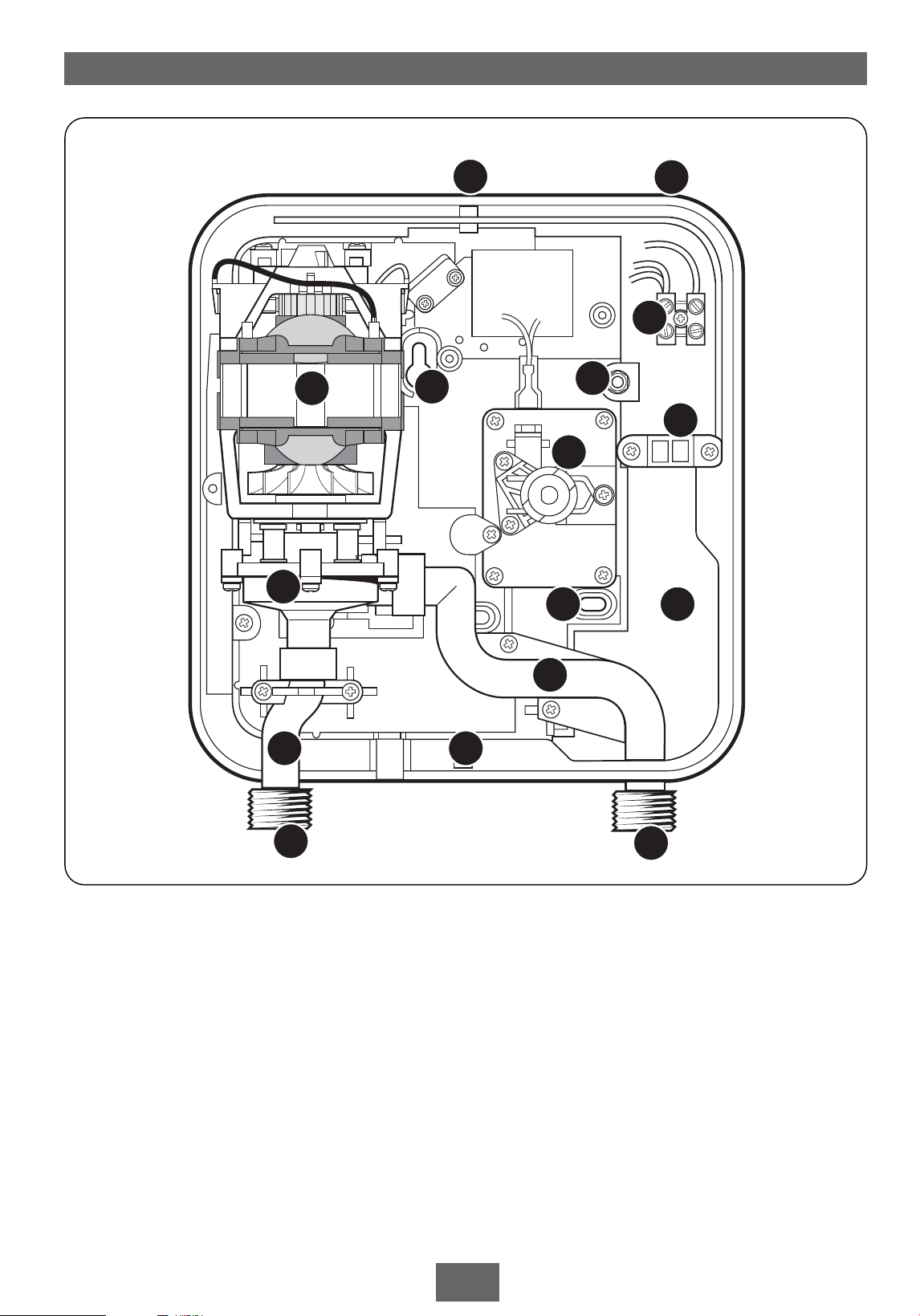
1 Top cable entry
2 Cover screw fixings
3 Terminal block
4 Cable clamp
5 Wall screw fixings
6 Rear cable entry
7 Switch assembly
8 Earth connection
9 Motor
10 Pump assembly
12
2
3
4
5
5 6
7
8
9
1 0
1 1
1 2
1 3
1 4
Fig.1
11 Inlet pipe
12 Outlet pipe
13 Inlet connection
14 Outlet connection
KEY TO MAIN COMPONENTS inside unit (fig.1)
Page 6

4
T40i
SITE REQUIREMENTS
Water
The installation must be in accordance with
Water Regulations/Byelaws.
To ensure correct operation, the T40i unit
must be connected to a gravity fed system of
hot and cold water of equal pressure (fig.2).
The T40i pump MUST NOT be connected
to the mains water supply.
The unit must be positioned BELOW the cold
water cistern and NOT placed in areas where it
will be subject to freezing conditions.
Position the unit where it will NOT be in direct
contact with water from the sprayhead.
Both hot and cold water supplies to the
existing bath/tap mixer valve MUST be direct
and separate from any other outlets or
connections.
DO NOT use jointing compound on any pipe
fittings for installation.
Note: The outlet of the T40i pump acts as a
vent and must not be connected to any form
of tap or fitting that is NOT recommended by
the manufacturer.
Generally there are four main types of hot and
cold water mixer systems to which the T40i
can be installed. These are shown in (fig.2)
through to (fig.5).
In each case, to ensure correct operation of
the booster pump, the top of the T40i unit
MUST be at least 230mm below the bottom of
the cold water cistern and the sprayhead must
be a minimum of 100mm below the water
level of the cold water cistern.
Note: Bath mixer valves incorporating a
diverter valve can have a high restriction to
water flow, so the expected improvement may
not be possible.
Water circuits supplying the T40i unit should
be installed so that the flow is not significantly
affected by other taps and appliances that are
being operated elsewhere on the premises.
Gate
valves
Gate
valve
Cold supply
Hot supply
Stop
valve
Cold
water
mains
supply
Hot water
cylinder
Isolating switch or
pull cord switch
(both fused at 3A)
Ring main
230mm min.
100mm
minimum
Water level
Outline of bath
or shower cubicle
Cold water
cistern
2' 6"
minimum
Fig.2 Typical gravity fed system with bath
tap/mixer valve arrangement
Whether the
mixer valve has
top or bottom
outlet, position
the T40i so the
hose is not
kinked or twisted
Fig.3 Mixer valve arrangement
Page 7

5
T40i
Fig.4 Push-on with blender/mixer valve
arrangement
Fig.5 Push-on type arrangement
SITE REQUIREMENTS
Electrical
THIS INSTALLATION MUST BE EARTHED.
This product must be permanently connected to
the electricity supply, via a double pole switch
with at least 3mm contact separation. This can
be a ceiling mounted pull cord switch, or a wall
mounted switch, both of which must be fused
at 3A. The switch must be readily accessible and
clearly identifiable, but out of reach of a person
using a fixed bath or shower, except for the
cord of a cord operated switch.
The installation and wiring must comply with
the current IEE regulations.
The supply cable and circuit protection must
conform with IEE wiring regulations and be
sufficient for the amperage required. In most
cases 1mm² twin and earth cable will be
adequate.
If in any doubt consult a qualified electrician or
contact Triton Customer Service for advice.
Page 8

6
T40i
FITTING TO THE WALL
Unscrew the top and bottom retaining screws
(fig.6) and lift the cover from the backplate.
Note: The control knob is an integral part of the
cover − DO NOT attempt to remove it.
Decide on the cable entry position, either top or
rear.
If top entry position is chosen, the cut-out in the
backplate must be removed (fig.7).
Loosely connect the flexible hose supplied to the
T40i inlet connection and the mixer valve outlet.
Using the backplate as a template, hold it
against the wall, making sure there is some slack
in the hose and mark the position of the fixing
holes (fig.8). Remove the flexible hose from the
T40i and mixer valve.
Drill and plug to suit the fixing screws supplied.
(The wallplugs provided are suitable for most brick
walls – use an appropriate masonry drill, but if the
wall is plasterboard or a soft building block, you
must use special wallplugs and an suitable drill
bit).
Screw the top fixing screw into position leaving
the base of the screw head protruding 6mm out
from the wall.
Hook the backplate over the top screw and fit
the bottom fixing screw into position.
The bottom fixing hole is elongated to allow for
out of square adjustment. Tighten both screws
when correctly positioned.
Fig. 6
Fig. 7
Fig. 8
Page 9

7
T40i
Existing
hose
Hose
supplied
Fig.9
HOSE CONNECTIONS
Fitting to:
Bath tap/mixer valve (fig.2)
Mixer valve (fig.3)
Push on with blender valve (fig.4)
Remove the existing sprayhead flexible hose
from bath tap/mixer valve/blender mixer
arrangement.
Screw one end of the flexible hose supplied, to
the T40i inlet connection using one of the
sealing washers to seal the joint. DO NOT
OVERTIGHTEN.
Screw the other end of the flexible hose to the
mixer outlet using the washer provided to seal
the joint. DO NOT OVERTIGHTEN.
Screw the sprayhead flexible hose to the outlet
of the T40i pump using the washer provided to
seal the joint. DO NOT OVERTIGHTEN.
DO NOT kink or twist the hoses.
Remove the sprayhead. Hold the end of the
hose to waste and turn the water on to flush the
system and to check for leaks. Turn off the
water. Replace the sprayhead and turn the
water on again. Leave running to waste until a
smooth (even if poor) flow of water is obtained.
Turn off the water.
Fitting to:
Push-on type connection (fig.5) and
(fig.9)
Unscrew the sprayhead from the existing hose
then connect the hose to the T40i inlet.
Note: This is only possible if the hose
terminates with a ½” BSP connection. Connect
the hose supplied to the T40i outlet using the
washer provided to seal the joint. DO NOT
OVERTIGHTEN.
Hold the end of the hose to waste and turn the
water on to flush the system and to check for
leaks. Turn off the water.
Connect the sprayhead to the supplied hose
using the washer provided.
Turn the water on again and leave running to
waste until a smooth (even if poor) flow of
water is obtained. Turn off the water.
Page 10

8
T40i
L
N
E
Terminal
block
Switch
Pump
Neon
indicator
Fig.10
Terminal
block
Cable
clamp
Fig.11
ELECTRICAL CONNECTIONS
Note: A double pole linked switch with a
minimum contact gap of 3mm in both poles
must be fitted in the circuit.
IMPORTANT: The T40i unit must be supplied
by fixed wiring. The supply cable must
conform to relevant tables in current IEE
regulations. The electrical rating of the T40i
is shown on the rating label within the unit.
Fig.10 shows a schematic wiring diagram.
SWITCH OFF THE ELECTRICITY SUPPLY AT THE
MAINS.
The cable entry points are shown in fig.1. The
cable can be surface clipped, hidden or via
20mm conduit.
Note: Conduit entry can only be from the rear.
Route the cable into the unit and connect to the
terminal block (fig.11) as follows:
Earth cable to terminal marked E
Neutral cable to terminal marked N
Live cable to terminal marked L
IMPORTANT: Fully tighten the terminal block
screws and make sure that no cable
insulation is trapped under the screws.
Note: The supply cable earth conductor must
be sleeved. The cable clamp (fig.10) is suitable
for up to 4mm² cable, but in most cases 1mm²
cable will be enough.
The earth continuity conductor of the electrical
installation must be effectively connected
electrically to all exposed metal parts of other
appliances and services in the room in which the
T40i is to be installed, to conform to current IEE
regulations.
The use of connections within the unit to supply
power to other equipment i.e. extractor fans,
pumps etc. will invalidate the guarantee.
DO NOT switch on the electricity supply
until the cover has been fitted.
WARNING!
This appliance must be earthed.
Page 11

9
T40i
'Dogs'
REPLACING THE COVER AND TESTING
Procedure
a) Make sure the switch spindle adaptor ‘dogs’
are positioned as shown (fig.12).
b) Position the control knob on the cover to
‘stop’ (fig.15).
c) Offer the cover to the unit and plug the
loose neon into the bracket that is located
inside the cover (fig.13).
Place the cover squarely over the backplate and
guide into position so that the extended ‘dogs’
of the spindle adaptor slot into the recess of the
control knob. Should any difficulty arise, recheck
the points above.
Secure the cover in position with the two
retaining screws. DO NOT OVERTIGHTEN.
Turn on the water supply at the mixer valve/tap
and adjust to a normal showering temperature.
Make sure the control knob is at the ‘stop’
position. Switch on the electricity supply at the
isolating switch.
Turn the control knob to the ‘start’ position
(fig.14). The pump will start and the neon will
illuminate. Check for an increase in water flow.
Turn the control knob to the ‘stop’ position
(fig.15). The water flow should decrease. Turn
off the water at the mixer valve/tap.
The installation should be checked for any leaks
from the hose connections.
Fig.13
Fig.12
Page 12

10
T40i
Fig.14
Fig.15
OPERATING
Ensure the electric isolating switch is on to the
T40i. Turn on the water supply at the mixer
valve/tap and adjust to a showering
temperature.
Switch the T40i control knob to ‘start’ (fig.14).
The pump will start and the neon will illuminate.
Adjust shower temperature as normal.
Note: With the push-on hose systems the T40i
pump should not be switched on until water
flows from the sprayhead.
When showering is completed, switch the T40i
control knob to ‘stop’ (fig.15).
Turn off the mixer valve or taps.
MAINTENANCE
It is recommended that the booster pump unit
and hoses be cleaned using a soft cloth and that
the use of abrasive or solvent cleaning fluids be
avoided.
Before cleaning, turn off the unit at the isolation
switch to avoid accidental switching on of the
booster pump.
IT IS MOST IMPORTANT TO KEEP THE EXISTING
SPRAYHEAD CLEAN IN ORDER TO MAINTAIN
THE PERFORMANCE OF THE SHOWER.
The hardness of water will determine the
frequency of cleaning. For example, if the
shower is used every day in a very hard water
area, it may be necessary to clean the sprayhead
on a weekly basis.
If the T40i pump is not used for lengthy periods,
it is recommended to turn on the water at the
mixer valve/tap then switch the pump on for
two or three minutes periodically to prevent the
motor shaft seals from seizing.
Do not run the T40i pump dry.
WARNING!
Do not use ‘powerful’ abrasive or solvent
cleaning fluids when cleaning the booster
pump as they may damage the plastic
fittings.
Page 13

11
T40i
3
5
4
2
1
1
6
7
Ref. Description Part No.
1 Pump & motor assembly 83100050
2 Microswitch 22003230
3 Terminal block & wires 82200380
4 Switch assembly 82500130
5 Cable clamp 70500820
6 Inlet pipe assembly 83304900
7 Outlet pipe assembly 83304910
− Cover assembly 80400010
− Flexible hose (chrome) 28100080
SPARE PARTS
Page 14

12
T40i
1 During use, the
water flow drops
to a reduced rate.
Pump stops
running.
2 During use, the
water flow ceases
but the pump
continues to run.
3 Water too hot or
too cold.
1.1 Interrupted power
supply.
1.2 Pump motor faulty.
2.1 Water starvation in
the system.
2.2 Air lock in pump.
3.1 Not product related
but problem with
existing water
heating system.
1.1.1 If the power neon is extinguished, check
consumer unit fuse or circuit breaker. If
blown, renew or reset as applicable. If it
fails again, consult a qualified electrician.
1.1.2 If the power neon is extinguished, check if
a general power cut. Check other
appliances and if necessary, contact local
Electricity Supply Company.
1.2.1 If the power neon is lit, have pump motor
checked by a qualified electrician or
contact Triton Customer Service.
2.1.1 Stop pump motor by switching to ‘stop’.
Check the cold water cistern is full. Ensure
water pipes are not blocked. Check there
is no simultaneous demand from the
cistern while showering.
2.2.1 Prime pump by running water through
unit without electricity switched on.
3.1.1 Consult qualified electrician or plumber.
FAULT FINDING
IMPORTANT: Switch OFF the electricity at the mains supply and remove the circuit fuse
before removing the cover from the T40i while attempting any fault finding inside the unit.
Problem/Symptom Cause Action/cure
It is advised all electrical maintenance/repairs to the T40i
should be carried out by a suitably qualified person.
Page 15

13
T40i
UKAS
QUALITY
M ANAGEMENT
003
Page 16

Service Policy
In the event of a complaint occurring, the
following procedure should be followed:
1 Telephone Customer Service on (024) 7637
2222 (08457 626591 in Scotland and in Northern
Ireland), having available the model number and
power rating of the product, together with the
date of purchase.
2 Triton Customer Service will be able to confirm
whether the fault can be rectified by either the
provision of a replacement part or a site visit from
a qualified Triton service engineer.
3 If a service call is required it will be booked and
the date of call confirmed. In order to expedite
your request, please have your postcode available
when booking a service call.
4 It is essential that you or an appointed
representative (who must be a person of 18 years
of age or more) is present during the service
engineer's visit and receipt of purchase is shown.
5 A charge will be made in the event of an
aborted service call by you but not by us, or
where a call under the terms of guarantee has
been booked and the failure is not product related
(i.e. scaling and furring, incorrect water pressure,
pressure relief device operation, electrical
installation faults).
6 If the product is no longer covered by the
guarantee, a charge will be made for the site visit
and for any parts supplied.
7 Service charges are based on the account being
settled when work is complete, the engineer will
then request payment for the invoice. If this is not
made to the service engineer or settled within ten
working days, an administration charge will be
added.
Replacement Parts Policy
Availability: It is the policy of Triton to maintain
availability of parts for the current range of
products for supply after the guarantee has
expired. Stocks of spare parts will be maintained
for the duration of the product’s manufacture and
for a period of five years thereafter.
In the event of a spare part not being available a
substitute part will be supplied.
Payment: The following payment methods can be
used to obtain spare parts:
1 By post, pre-payment of pro forma invoice by
cheque or money order.
2 By telephone, quoting credit card (MasterCard
or Visa) details.
3 By website order, www.tritonshowers.co.uk
TRITON STANDARD GUARANTEE
Triton Plc guarantee this product against all
mechanical and electrical defects arising from
faulty workmanship or materials for a period of
one year for domestic use only, from the date of
purchase, provided that it has been installed by a
competent person in full accordance with the
fitting instructions.
Any part found to be defective during this
guarantee period we undertake to repair or
replace at our option without charge so long as
it has been properly maintained and operated in
accordance with the operating instructions, and
has not been subject to misuse or damage.
This product must not be taken apart, modified
or repaired except by a person authorised by
Triton Plc. This guarantee applies only to
products installed within the United Kingdom
and does not apply to products used
commercially. This guarantee does not affect
your statutory rights.
What is not covered:
1 Breakdown due to: a) use other than
domestic use by you or your resident family;
b) wilful act or neglect; c) any malfunction
resulting from the incorrect use or quality of
electricity, gas or water or incorrect setting of
controls; d) faulty installation.
2 Repair costs for damage caused by foreign
objects or substances.
3 Total loss of the product due to nonavailability of parts.
4 Compensation for loss of use of the product
or consequential loss of any kind.
5 Call out charges where no fault has been
found with the appliance.
6 The cost of repair or replacement of pressure
relief devices, sprayheads, hoses, riser rails
and/or wall brackets, isolating switches, electrical
cable, fuses and/or circuit breakers or any other
accessories installed at the same time.
7 The cost of routine maintenance,
adjustments, overhaul modifications or loss or
damage arising therefrom, including the cost of
repairing damage, breakdown, malfunction
caused by corrosion, furring, pipe scaling,
limescale, system debris or frost.
Triton Plc
Shepperton Park
Caldwell Road
Nuneaton
Warwickshire CV11 4NR
Customer Service:
(024) 7637 2222
Scottish and Northern Ireland
Customer Service:
08457 626591
Trade Installer Hotline:
(024) 7632 5491
Fax: (024) 7632 4564
www.tritonshowers.co.uk
E mail: technical@triton.plc.uk
 Loading...