

Triton T300si Installation And Operating Instructions Manual
Installers please note these InstructIons are to be left wIth the user
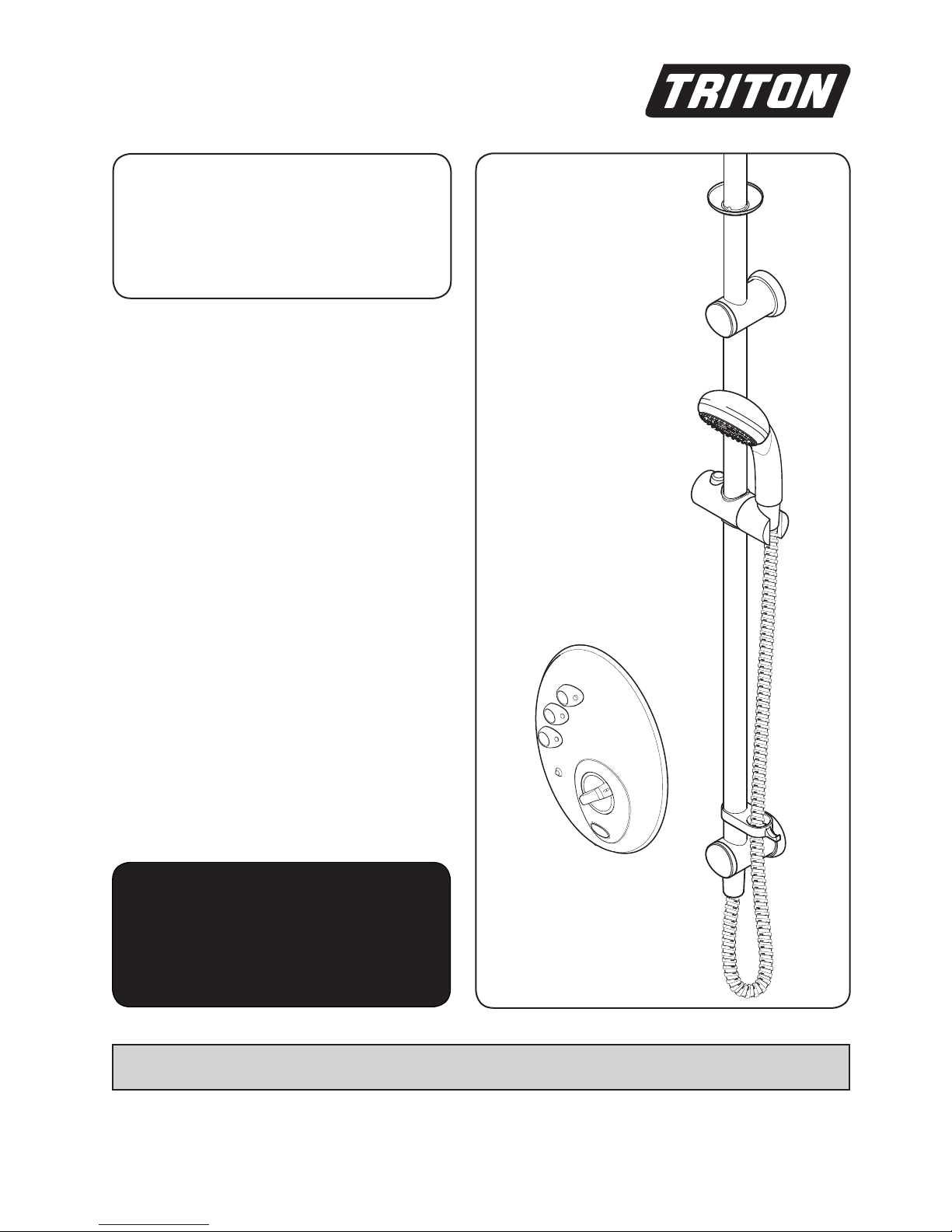
T300si wireless
remote
electric shower
2180520B June 2006
Installation and
operating
instructions

T300si wireless remote electric shower
CONTENTS Page
Important safety information 1
Introduction 2
Specifications 2
Advice to users 3
Key to main components 4 – 5
Electrical requirements 6 – 7
Battery safety guidelines 8 – 9
Water requirements 10
Installation options 11 – 12
Siting of the shower 13 – 14
Installation Option 1: Bulkhead fitting 15 – 23
Fitting the remote pack 15 – 16
Plumbing connections 17 – 19
Fitting the bulkhead 20 – 21
Fitting the riser rail 22 – 23
Fitting the hose and showerhead 23
Installation Option 2: Fitting through the ceiling 24 – 30
Fitting the ceiling riser rail 25 – 26
Fitting the remote pack 27 – 28
Plumbing connections 29 – 30
Electrical connections 31
Fitting the control panel bracket 32
Fitting the control panel 32
Fitting the remote pack cover 32
Associating the shower unit 33
Commissioning 34
Operating the shower 35 – 36
Operating functions 37 – 38
Continuous and timed operation 38
Battery life 38
Adjusting the showerhead 39
Cleaning 40
Instructions for installers and service engineers only 41
Spare parts 42 – 43
Fault finding 44 – 45
Guarantee, service policy, etc. rear cover

T300si wireless remote electric shower
Please Read This imPoRTanT safeTy infoRmaTion
Products manufactured by Triton are safe and without risk provided they are installed, used and
maintained in good working order in accordance with our instructions and recommendations.
WARNING: DO NOT operate shower if frozen, or suspected of being frozen. It must thaw
out before using.
DO NOT operate the unit if the showerhead or spray hose becomes damaged.
DO NOT restrict flow out of shower by placing showerhead in direct contact with your body.
DO NOT operate the shower if water ceases to flow during use or if water has entered inside
the unit because of an incorrectly fitted cover.
1 GENERAL
1.1 Isolate the electrical and water supplies before
removing the cover.
1.2 Read all of these instructions and retain them
for later use.
1.3 DO NOT take risks with plumbing or electrical
equipment.
1.4 Isolate electrical and water supplies BEFORE
proceeding with the installation.
1.5 The unit must be mounted onto the finished
wall surface (on top of the tiles). DO NOT tile
up to unit after fixing to wall.
1.6 Contact Customer Service (see back page), if
any of the following occur:
a) If it is intended to operate the shower at
pressures above the maximum or below the
minimum stated.
b) If the unit shows a distinct change in
performance.
c) If the shower is frozen.
1.7 If it is intended to operate the shower in areas
of hard water (above 200 ppm temporary
hardness), a scale inhibitor may have to be
fitted. For advice on the Triton Scale Inhibitor,
contact Triton Customer Service.
1.8 The showerhead must be cleaned regularly
with descalent to remove scale and debris,
otherwise restrictions to the flow on the outlet
of the unit will result in higher temperatures
and could also cause the Pressure Relief Device
in the unit to operate.
1.9 This product is not suitable for mounting into
steam rooms or steam cubicles.
2 PLUMBING
2.1 The plumbing installation must comply with
Water Regulations, Building Regulations or
any particular regulations as specified by Local
Water Company or Water Undertakers and
should be in accordance with BS 6700.
2.2 The supply pipe must be flushed to clear debris
before connecting to the shower unit.
2.3 DO NOT solder pipes or fittings within 300mm
of the shower unit, as heat can transfer along
the pipework and damage components.
2.4 DO NOT fit any form of outlet flow control as
the outlet acts as a vent for the heater can.
2.5 DO NOT use excessive force when making
connections to the flexible hose or
showerhead, finger tight is sufficient.
2.6 All plumbing connections MUST be completed
BEFORE making the electrical connections.
3 ELECTRICAL
3.1 The installation must comply with BS 7671
‘Requirements for electrical installations’ (IEE
wiring regulations), building regulations or any
particular regulations as specified by the local
Electrical Supply Company.
3.2 This appliance MUST be earthed.
3.3 In accordance with ‘The Plugs and Sockets etc.
(Safety) Regulations 1994’, this appliance is
intended to be permanently connected to the
fixed wiring of the electrical mains system.
3.4 Make sure all electrical connections are tight to
prevent overheating.
3.5 Fuses do not give personal protection against
electric shock.
3.6 To enhance electrical safety a 30mA residual
current device (RCD) should be installed in all
UK electric and pumped shower circuits. This
may be part of the consumer unit or a separate
unit.
3.7 Switch off immediately at isolating switch if
water ceases to flow during use.
3.8 Other electrical equipment i.e. extractor fans,
pumps must not be connected to the circuits
within the unit.
3.9 Switch off at isolating switch when not in use.
This is a safety procedure recommended with
all electrical appliances.
3.10 As with all electrical appliances it is
recommended to have the shower and
installation checked at least every two years by
a competent electrician to make sure there is
no deterioration due to age and usage.
1

T300si wireless remote electric shower
2
INTRODUCTION
This book contains all the necessary fitting and
operating instructions for your Triton T300si
wireless remote electric shower — please read
them carefully.
The shower installation must be carried out by a
suitably qualified person and in the sequence of
this instruction book.
Care taken during the installation will provide a
long, trouble-free life from your shower.
Replacement parts can be ordered from Triton
Customer Service. See ‘spare parts’ for details.
Due to continuous improvement and updating,
specification may be altered without prior notice.
SPECIFICATIONS
Electrical
Nominal power Nominal power
rating at 240V rating at 230V
9.5kW – (40A MCB rating) 8.7kW – (40A MCB rating)
10.5kW – (45A MCB rating) 9.6kW – (40A MCB rating)
Water
Inlet connection – 15mm diameter.
Outlet connection – ½” BSP male thread.
Entry Points (for remote pack)
Water – bottom or back.
Cable – top or back.
Materials
Backplate, cover, controls, showerhead – ABS.
Sprayplate – Acetal.
Elements – Minerally insulated corrosion resistant
metal sheathing.
Dimensions (in mm)
control panel remote pack
Height 235 338
Width 180 208
Depth 40 98
Standards and Approvals
Splashproof rating IPX4.
Complies with the requirements of current
British and European safety standards for
household and similar electrical appliances.
Complies with requirements of the British
Electrotechnical Approvals Board (BEAB).
Meets with Compliance with European New
Approach Directives (CE).
Complies with the requirements of the Radio
and Telecommunications Terminal Equipment
(RTTE) Directive 1999/5/EC.
To check the product suitability for
commercial and multiple installations, please
contact Triton’s specification advisory service
before installation.
Telephone: +44 (0) 24 7632 5491
Facsimile: +44 (0) 24 7632 4564
E mail: technical@triton.plc.uk

T300si wireless remote electric shower
3
ADVICE TO USERS
The following points will help you understand
how the shower operates:
a. The electric heating elements operate at a
constant rate at your chosen power setting. It is
the rate of the water passing through the heater
unit which determines the shower temperature
at a given setting. (The slower the flow the
hotter the water becomes, and the faster the
flow the cooler the water).
b. During the winter the cold water supply
will be cooler than in the summer months.
Therefore, the temperature of the water will
vary from season to season on any one setting
of the control buttons, e.g. if you have chosen
'Economy' power for your preferred shower
temperature in the summer, you will have
to select the 'High' setting and adjust the
temperature control during the winter months.
c. The stabiliser valve minimises variations in
shower temperature during mains water pressure
changes. If changes in shower temperature are
experienced during normal use, it will most
likely be caused by the water pressure falling
near to or below the minimum level. The drop
in pressure may be due to water being drawn
off at other points in the house whilst the
shower is in use. If pressure drops appreciably
below the minimum, the heating elements will
automatically cut out.
If ever the water becomes too hot and
you cannot obtain cooler water, first
check the showerhead has not become
blocked.
ELECTROMAGNETIC COMPATIBILITY
This product is intended for domestic
use.
This product may temporarily be affected
by electromagnetic disturbance near to
the installation that could cause temporary
operation of the low pressure indicator
together with switching to the cold power
selection. If problems persist, contact Triton
Customer Service (see rear page).
IMPORTANT: When first installed (or
following replacement of the PRD), the
unit will be empty. It is essential the
heater assembly contains water before
the elements are switched on. As this
unit has electronic control, it is vital that
the commissioning procedure is followed.
Failure to carry out this operation will
result in damage to the unit and will
invalidate the guarantee.
T300si wireless remote electric shower
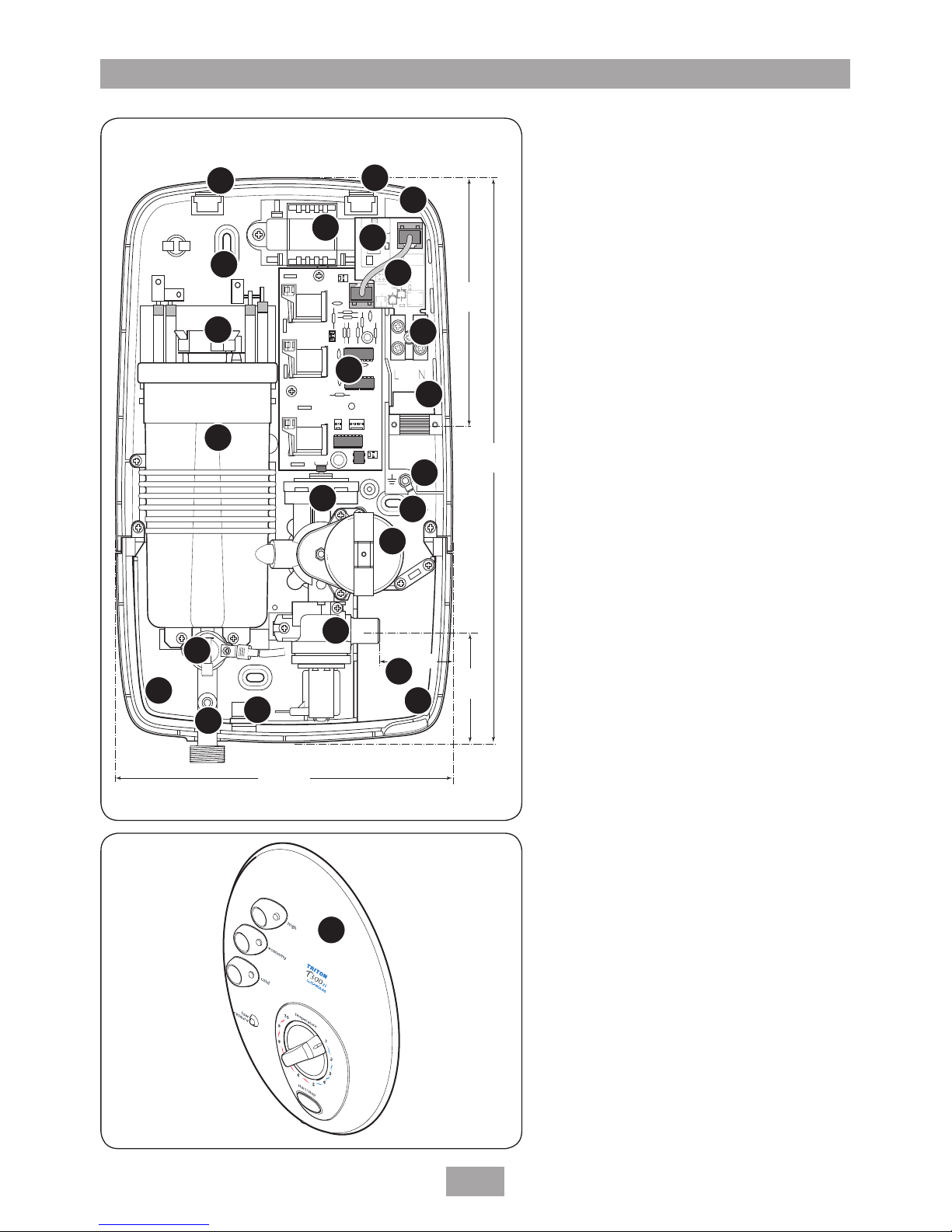
4
KEY TO MAIN COMPONENTS
Remote pack (Fig.1)
1. Top cable entry
2. Bottom pipe entry
3. Rear pipe entry area
4. Rear cable entry area
5. Wall screw fixing
6. Terminal block
7. Printed circuit board
8. RF module
9. RF Data cable
10. Stabilising valve
11. Solenoid valve
12. Guide pockets
13. Can and element assembly
14. Thermal safety cut-out (main)
15. Earth connection
16. Thermal cut-out (outlet)
17. Outlet pipe
18. Transformer
19. Stepper motor
20. Trimplate
Control panel (Fig.2)
21. Control panel
338
mm
68
mm
145
mm
208 mm
47 mm
NOTE: Not all wiring shown for reasons of clarity
Fig.2
Fig.1
1
2
3
4
5
5
6
7
8
10
11
12
12
12
13
14
15
16
17
18
19
20
21
9
T300si wireless remote electric shower
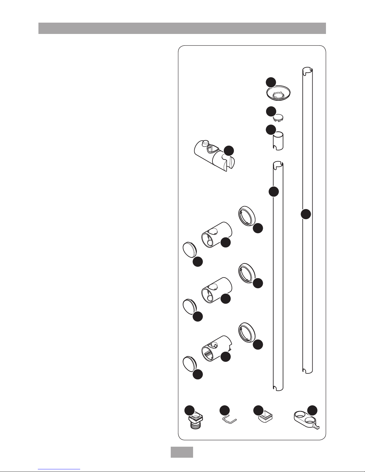
5
Fig.3
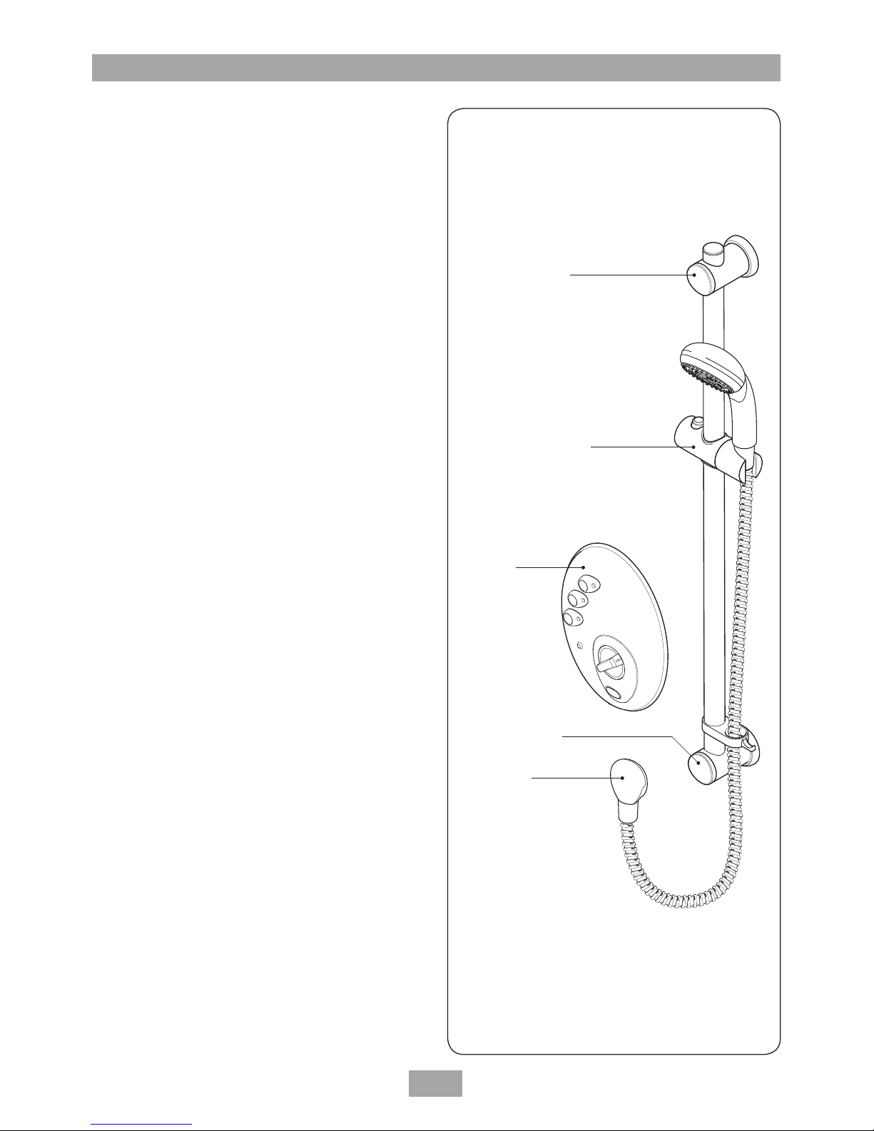
KEY TO MAIN COMPONENTS
Riser rail contents (Fig.3)
22. Showerhead holder
23. Bridging wall bracket (lug on inside)
24. Guide bracket (no lugs inside)
25. Bottom bracket
26. Bracket trim ring (3 off)
27. Bracket end trim (3 off)
28. Water outlet fitting retaining clip
29. Blanking plug
30. Heated water pipe hose connector
31. Ceiling trim
32. Riser rail end trim
33. Riser rail – 40mm
34. Riser rail – 700mm
35. Riser rail – 940mm
36. Hose retainer
37. Fixing screws and wall plugs
(not shown)
Pack contents
Control panel
Remote pack
Riser rail kit
Bulkhead
2m heated water tube (white)
3.3m heated water tube (white)
10mm push fit elbow
PRD tube (clear)
Flexible hose
Plumbing connection kit
Fixing kit
Instructions, guarantee, template etc.
22
23
24
25
26
27
28
29
30
31
32
33
34
35
36
26
26
27
27
T300si wireless remote electric shower
6
ELECTRICAL REQUIREMENTS
The installation, supply cable and circuit
protection must conform with BS7671 (IEE
wiring regulations) and be sufficient for the
amperage required.
The following notes are for guidance only:
1 The shower must only be connected to a
230 – 240V ac supply. If you are installing
a shower with a kilowatt rating above 9kW,
it is advisable to contact the local electricity
supply company.
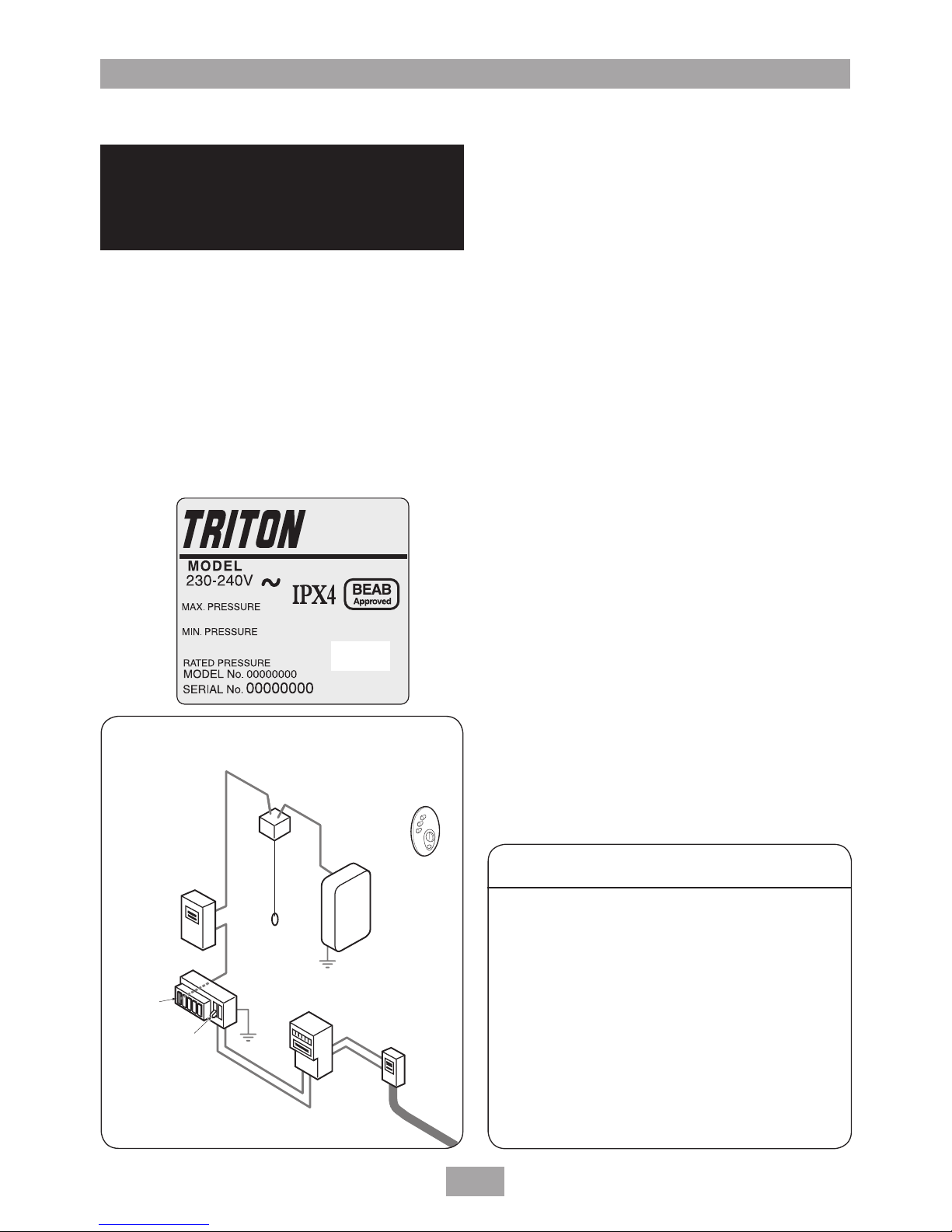
1.1 The electrical rating of the shower is shown
on the rating label (Fig.4) within the unit.
2 Before making any sort of electrical
connection within the installation, make
sure that no terminal is live. If in any
doubt, switch off the whole installation at
the consumer unit.
3 The shower must be connected to its own
independent electrical circuit. IT MUST
NOT be connected to a ring main, spur,
socket outlet, lighting circuit or cooker
circuit.
3.1 The electrical supply must be adequate for
the loading of the unit and existing circuits.
4 Check your consumer unit (main fuse box)
has a main switch rating of 80A or above
and that it has a spare fuse way which will
take the fuse or miniature circuit breaker
(MCB) necessary for the shower (Fig.5).
4.1 If your consumer unit has a rating below
80A or if there is no spare fuse way, then
the installation will not be straightforward
and may require a new consumer unit
serving the house or just the shower.
4.2 You will need to contact the local electricity
company. They will check the circuit and
carry out what is necessary. They will also
check the main bonding.
5 The earth continuity conductor of the
electrical installation must be effectively
connected electrically to all exposed metal
Shepperton Park,
Triton Road, Nuneaton,
Warwickshire, CV11 4NR
Meter
Incoming
supply
fuse
Meter
tails
Consumer
unit
Pull cord
isolating switch
Remote
pack
Control
panel
Fuse or
MCB
RCD
(can be part of
consumer unit)
80A or 100A
main switch
Fig.5 Diagrammatic view (not to scale)
Fig.4
WARNING!
THIS APPLIANCE MUST BE
EARTHED
Table A
CIRCUIT PROTECTION
unit cartridge
rating MCB fuse
7.0kW 30/32A 30A
7.5kW 32A 35A
8.0kW 40A 35A
8.5kW 40A 40A
9.0kW 40A 40A
9.5kW 40/45A 45A
10.5kW 45A 45A

T300si wireless remote electric shower
7
parts of other appliances and services
in the room in which the shower is to
be installed, to conform to current IEE
regulations.
5.1 All exposed metallic parts in the bathroom
must be bonded together using a cable of
at least 4mm2 cross sectional area. These
parts include metal baths, radiators, water
pipes, taps and waste fittings.
6 For close circuit protection DO NOT use a
rewireable fuse. Instead use a suitably rated
miniature circuit breaker or cartridge fuse
(see table A).
6.1 In the interest of electrical safety a 30mA
residual current device (RCD) should be
installed in all UK electric and pumped
shower circuits. This may be part of the
consumer unit or a separate unit.
7 A 45 amp double pole isolating switch with
a minimum contact gap of 3mm in both
poles must be incorporated in the circuit.
7.1 It must have a mechanical indicator
showing when the switch is in the
OFF position, and the wiring must be
connected to the switch without the use of
a plug or socket outlet.
7.2 The switch must be accessible and clearly
identifiable, but out of reach of a person
using a fixed bath or shower, except for
the cord of a cord operated switch, and
should be placed so that it is not possible
to touch the switch body while standing
in a bath or shower cubicle. It should be
readily accessible to switch off after using
the shower.
8 Where shower cubicles are located in any
rooms other than bathrooms, all socket
outlets in those rooms must be protected
by a 30mA RCD.
9 To obtain full advantage of the power
provided by the shower, use the shortest
cable route possible from the consumer
unit to the shower.
9.1 The current carrying capacity of the cable
must be at least that of the shower circuit
protection (see table B).
9.2 It is also necessary to satisfy the
disconnection time and thermal
constraints which mean that for any given
combination of current demand, voltage
drop and cable size, there is a maximum
permissible circuit length.
10 The shower circuit should be separated
from other circuits by at least twice the
diameter of the cable or conduit.
10.1 The current rating will be reduced if the
cabling is bunched with others, surrounded
by thermal loft or wall insulation or placed
in areas where the ambient temperature
is above 30°C. Under these conditions,
derating factors apply and it is necessary to
select a larger cable size.
10.2 In the majority of installations, the cable
will unavoidably be placed in one or more
of the above conditions. This being so, it is
strongly recommended to use a minimum
of 10mm² cabling throughout the shower
installation.
10.3 It is essential that individual site conditions
are assessed by a competent electrician
to determine correct cable size and
permissible circuit length.
Table B
Twin and earth PVC insulated cable
CURRENT CARRYING CAPACITY
installed in an
insulated wall
6mm²
32A
10mm²
43A
16mm²
57A
in conduit
trunking
6mm²
38A
10mm²
52A
16mm²
69A
clipped direct or
buried in a non-
insulated wall
6mm²
46A
10mm²
63A
16mm²
85A
Note: Cable selection is dependent on
derating factors

T300si wireless remote electric shower
8
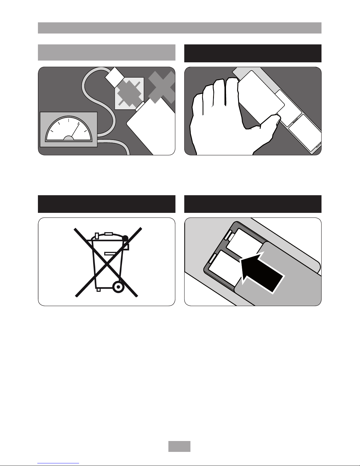
Store unused batteries in their packaging and
away from metal objects which may cause a
short-circuit.
Remove dead batteries from equipment and
all batteries from equipment you know you are
not going to use for a long time. Otherwise the
batteries may leak and cause damage.
Never dispose of batteries in fire as this may
cause them to explode.
BATTERY SAFETY GUIDELINES
Used correctly, domestic batteries are a safe
and dependable source of portable power.
Problems can occur if they are misused or abused
— resulting in leakage or, in extreme cases, fire
or explosion.
Here are some simple guidelines to safe battery
use designed to eliminate any such problems.
Take care to fit your batteries correctly, observing
the plus and minus marks on the battery and
appliance.
Replace the whole set of batteries at one time,
taking care not to mix old and new batteries or
batteries of different types.
ALWAYS
ALWAYS
ALWAYS
ALWAYS
NEVER
T300si wireless remote electric shower
9
Supervise children if they are replacing batteries
themselves in order to ensure these guidelines
are followed.
Make sure battery compartments are secure.
Never attempt to recharge ordinary batteries,
either in a charger or by applying heat to them.
There are special rechargeable batteries which
are marked as such.
Always dispose of batteries in an environmentally
friendly manner and in accordance with local
regulations.
PUBLISHED BY THE BRITISH BATTERY MANUFACTURERS ASSOCIATION
NEVER
ALWAYS
ALWAYS
+
-
ALWAYS
T300si wireless remote electric shower
10
WATER REQUIREMENTS
The installation must be in accordance with
Water Regulations/Bylaws. To ensure activation
of the heating elements, the shower must be
connected to a mains water supply with a
minimum running pressure of 100 kPa (1.0 bar)
at a minimum flow rate of nine litres per minute.
For the 10.5kW rated shower, the minimum
running pressure must be 150 kPa (1.5 bar) at a
minimum flow rate of eleven litres per minute.
For all units the maximum static pressure must
be 1000 kPa (10 bar).
If in any doubt, the pressure should be checked.
Note: If the stated flow rate is not available,
it may not be possible to achieve optimum
performance from the unit throughout the year.
The water supply can be taken from a cold water
storage cistern provided there is a minimum
head of ten metres (fifteen metres for the
10.5kW model). Minimum head is the vertical
distance from the base of the cistern to the
showerhead. It must be an independent supply
to the shower only.
If it is intended to operate the shower at
pressures above the maximum or below the
minimum stated, contact Customer Service for
advice.
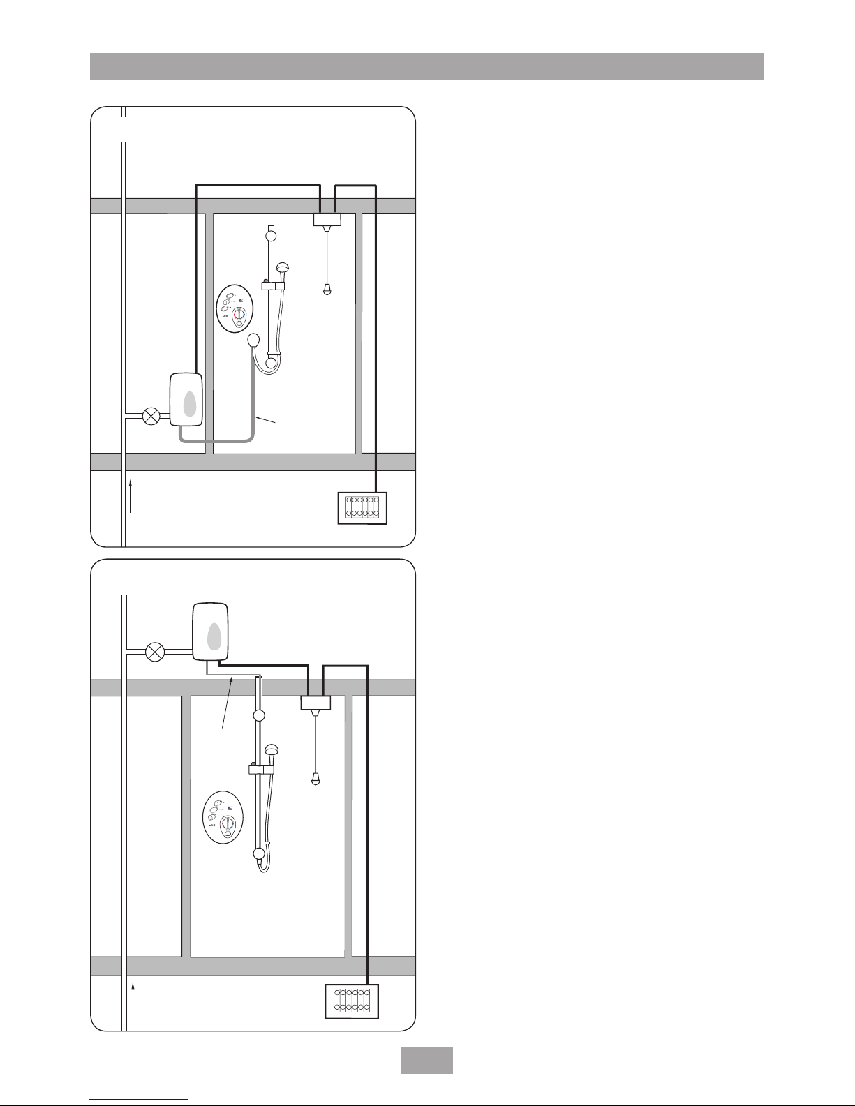
Fig.6 shows a typical system layout for bulkhead
and riser rail arrangement.
Fig.7 shows a typical system layout for the
through riser rail arrangement.
Isolating
stopvalve
Remote
pack
Double
pole
isolating
switch
Separate permanently
connected supply
from consumer unit
Mains
water
supply
Control
Panel
Heated
water pipe
Mains electric supply
(via double pole switch)
Fig.6 Diagrammatic view (not to scale)
Isolating
stopvalve
Remote
pack
Double
pole
isolating
switch
Mains
water
supply
Control
panel
Heated
water pipe
Mains electric supply
(via double pole switch)
Separate permanently
connected supply
from consumer unit
Fig.7 Diagrammatic view (not to scale)
T300si wireless remote electric shower
11
Bridging bracket
Showerhead holder
Control
panel
Bottom bracket
Bulkhead
Fig.8 Bulkhead fitting
INSTALLATION OPTIONS
Bulkhead fitting
The control panel is installed onto a tiled wall.
The remote pack is behind an adjoining wall with
heated water pipe running to bulkhead (Fig.8).
Stand-alone riser rail assembly.
Through the ceiling fitting
Here the remote pack is installed in the loft with
the heated water pipe running down the inside
of the riser rail. Water outlet at the bottom of
the riser rail. Fig.9 shows the short version using
two brackets, while Fig.10 shows the longer rail
option using all three brackets.
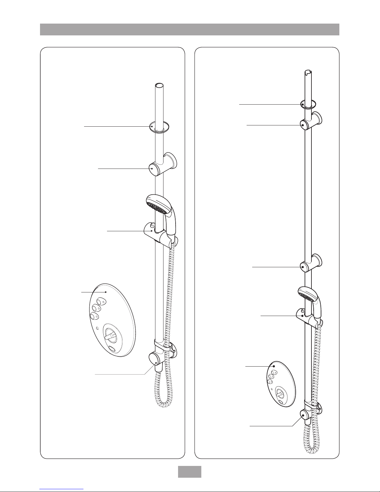
T300si wireless remote electric shower
12
Bridging bracket
Showerhead holder
Control panel
Bottom bracket
Ceiling trim
Guide bracket
Showerhead holder
Control panel
Bottom bracket
Bridging bracket
Ceiling trim
Fig.9 Through the ceiling fitting (short) Fig.10 Through the ceiling fitting (long)
T300si wireless remote electric shower
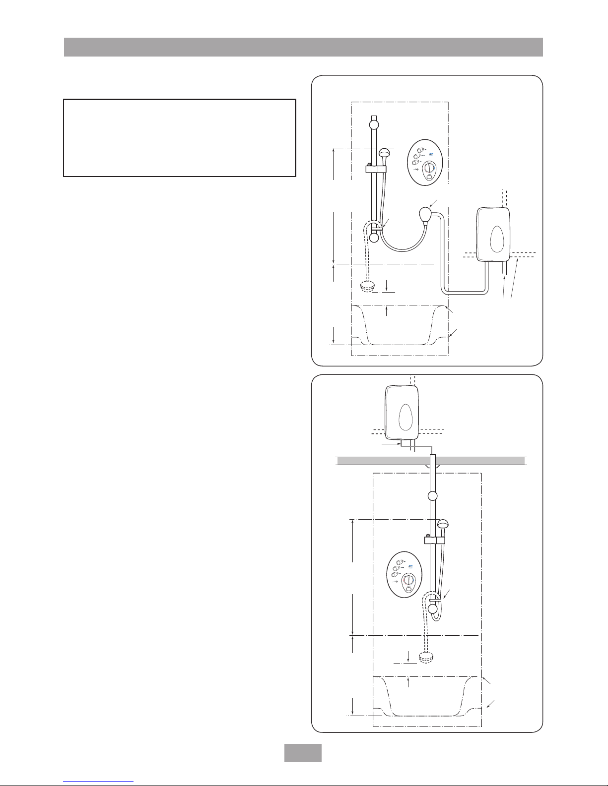
13
Outline of bath
or shower tray
25 mm minimum
Hose
retainer
Heated
water pipe
Mains cold water supply.
Bottom entry can be surface
mounted. All other entries
must be from rear.
Spillover
level
Height of
showerhead
to suit user's
requirement
Control
panel
must not
be within
1 metre
from base
SITING OF THE SHOWER
IMPORTANT: If installing onto a tiled wall
always mount the unit on the surface of the
tiles. NEVER tile up to the unit.
Refer to Fig.11 and Fig.12 for correct siting of
the shower.
Position the control panel where it will NOT
be in direct contact with water from the
showerhead. Position the remote pack vertically
and is accessible for maintenance purposes.
Note: Water Regulations requires that the
showerhead be ‘constrained by a fixed or sliding
attachment so that it can only discharge water at
a point not less than 25mm above the spill-over
level of the relevant bath, shower tray or other
fixed appliance’. The use of the supplied hose
retainer will usually meet this requirement, but
if the showerhead can be placed within a bath,
basin or shower tray, then a double check valve,
or a similar device, must be fitted in the supply
pipework to prevent back-flow.
Outline of bath
or shower tray
Bulkhead can
be mounted either
side of riser rail
25 mm minimum
Hose
retainer
Heated
water pipe
Mains cold
water supply.
Bottom entry
can be surface
mounted.
All other entries
must be from rear.
Spillover
level
Height of
sprayhead
to suit user's
requirement
Control
panel
must not
be within
1 metre
from base
Control
panel
Fig.11
WARNING!
The shower must not be positioned
where it will be subjected to freezing
conditions.
Fig.12
 Loading...