


Owner’s Manual
SmartOnline™ 3-Phase 10kVA Intelligent True On-Line UPS System (Tower)
Input (Voltage/Phase): 270 - 485V AC / Y, 3Ø4W
Output (Voltage/Phase): User-Selectable 220/230/240V AC / 1Ø2W
For all UPS system modules (power module and battery module) sold either separately or combined. Select UPS system modules may include separate instruction or warning sheets which should be used in conjunction with this manual.
Register on-line for a chance to win a FREE Tripp Lite product! www.tripplite.com/warranty
|
|
|
|
|
|
|
|
|
|
|
|
|
|
|
|
|
|
|
|
Important |
2 |
|||
|
|
|||
|
|
|||
Control Panel |
3 |
|||
|
|
|||
|
|
|||
Rear Panels |
4 |
|||
|
|
|||
|
|
|
|
|
Installation |
5 |
|||
|
|
|||
|
|
|||
Operation (Normal Conditions) |
8 |
|||
|
|
|||
|
|
|||
Operation (Special Conditions) |
10 |
|||
|
|
|||
|
|
|||
Communications |
12 |
|||
|
|
|||
|
|
|
|
|
Service |
14 |
|||
|
|
|||
|
|
|||
Warranty |
14 |
|||
|
|
|||
|
|
|||
Specifications |
15 |
|||
|
|
|
|
|
|
|
|
|
|
Español / Français / Deutsche / Русский |
16/31/46/61 |
|||
|
|
|
|
|
1111 W. 35th Street • Chicago, IL 60609 USA
(773) 869-1234 • www.tripplite.com
Copyright ©2004 Tripp Lite. All rights reserved. SmartOnline™ is a trademark of Tripp Lite.

Important Safety Warnings
SAVE THESE INSTRUCTIONS. This manual contains important instructions and warnings that should be followed during the installation and maintenance of all Tripp Lite SmartOnline 3-Phase UPS Systems and their batteries.
UPS Location Warnings
•Install your UPS indoors, away from heat, direct sunlight, dust, and excess moisture or other conductive contaminants.
•Install your UPS in a structurally sound area. Your UPS is extremely heavy; take care when moving and lifting the unit.
•Only operate your UPS at indoor temperatures between 32° F and 104° F (between 0° C and 40° C). For best results, keep indoor temperatures between 62° F and 84° F (between 17° C and 29° C).
•Leave adequate space around all sides of the UPS for proper ventilation: 12 in. (30 cm.) clearance at the rear; 4 in. (10 cm.) at sides and on top.
•Do not install the UPS near magnetic storage media, as this may result in data corruption.
UPS Connection Warnings
•The power supply for this unit must be three phase rated in accordance with the equipment nameplate. It also must be suitably grounded according to all applicable local electrical wiring regulations.
Equipment Connection Warnings
•Do not use Tripp Lite UPS Systems in life support applications in which a malfunction or failure of a Tripp Lite UPS System could cause failure or significantly alter the performance of a life support device.
•Connect your UPS's Grounding Terminal to a grounding electrode conductor.
•The UPS system contains its own energy source (battery). The output terminals may be live even when the UPS is not connected to an AC supply.
Battery Warnings
•Your UPS does not require routine maintenance. Do not open your UPS for any reason. There are no user-serviceable parts inside.
•The batteries in your battery module are recyclable. Refer to local codes for disposal requirements, or if in the USA call 1-800-SAV-LEAD (1-800-728-5323)for complete recycling information. CAUTION: Do not dispose of the batteries in a fire, as this could cause the battery to explode.
•Because the batteries present a risk of electrical shock and burn from high short-circuit current, batteries should be changed only by trained service personnel observing proper precautions. Consult your battery module manual before proceeding. Remove watches, rings, and other metal objects. Use tools with insulated handles. Wear rubber gloves and boots. Do not lay tools or metal parts on top of the batteries. Do not short or bridge the battery terminals with any object. Disconnect the charging source prior to connecting or disconnecting battery terminals. Determine if the batteries are inadvertently grounded. If inadvertently grounded, remove the source of the ground. Contact with any part of a grounded battery can result in electrical shock. The likelihood of such shock will be reduced if such grounds are removed during installation and maintenance.
•Connect only Tripp Lite battery packs to your UPS's external battery connectors.
•Do not operate your UPS without batteries.
•Fuses should be replaced only by factory authorized personnel. Blown fuses should be replaced only with fuses of the same number and type.
•Potentially lethal voltages exist within this unit as long as the battery supply is connected. Service and repair should be done only by trained personnel. During any service work, the UPS should be turned off or put into manual bypass.
•During "hot-swap" battery replacement (when the UPS is on manual bypass and connected equipment is turned ON) your UPS will be unable to provide battery backup in the event of a blackout.
•Do not connect or disconnect the battery modules while the UPS is operating from the battery supply or when the unit is not in bypass mode.
2
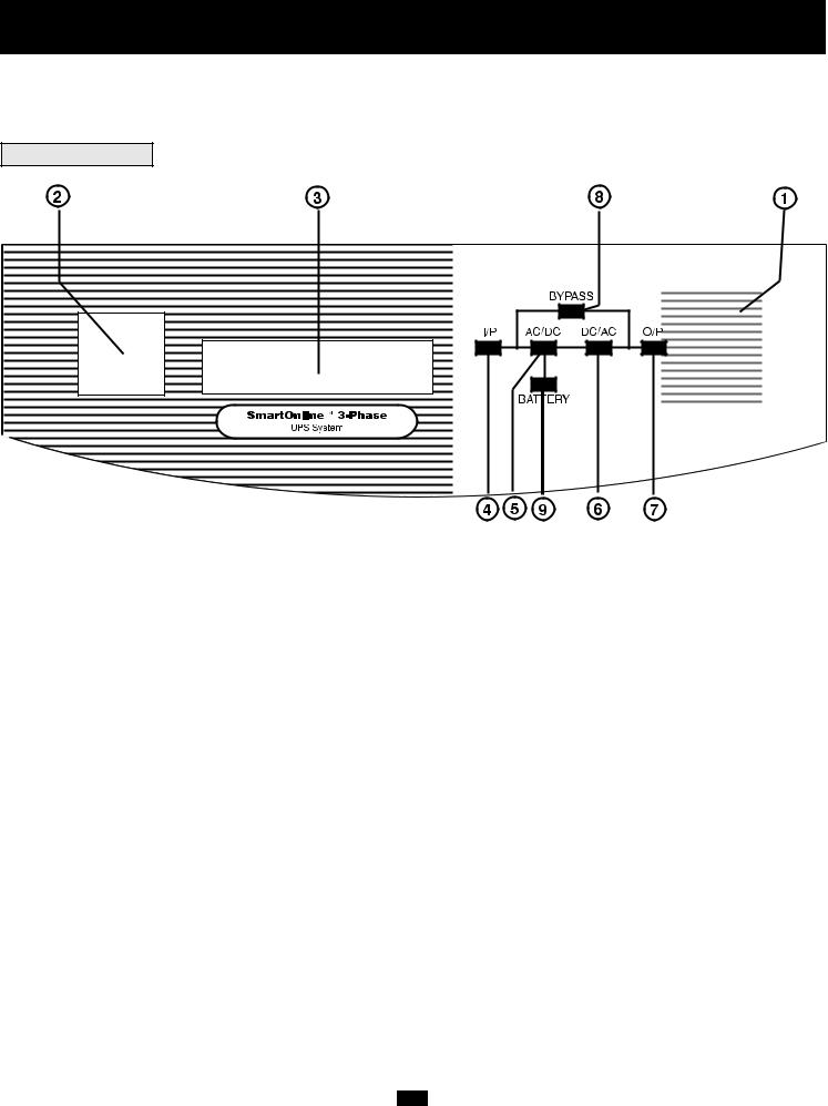
Control Panel
There are two separate UPS system modules: a power module and a battery module. Familiarize yourself with the location and function of the features on each module before installing and operating your UPS system. The power module is the only module which includes front panel features.
FRONT PANEL
SELECT |
ON |
|
|
|
OFF |
1."ON/OFF" Switch: This momentary rocker switch turns the UPS System's inverter ON and OFF.
2."SELECT" Button: This button performs two functions: it allows you to browse through different power readings on the LCD Display by momentarily pressing the button; it also allows you to silence the UPS alarm by pressing and holding the button for 3 seconds.
3.LCD Display: This backlit (16x2 character) dot matrix display indicates a wide range of UPS operating conditions and diagnostic data. It will illuminate after you have properly completed installation and start-up and after the "ON/OFF" Switch is turned ON.
4."I/P" (Input) LED: This green light will illuminate constantly to indicate an AC input supply is present.
5."AC/DC" (Converter) LED: This green light will illuminate constantly to indicate the UPS's AC/DC converter is activated.
6."DC/AC" (Inverter) LED: This green light will illuminate constantly to indicate the UPS's DC/AC inverter is activated.
7."O/P" (Output) LED: This green light will illuminate constantly to indicate your UPS is supplying AC power to connected equipment.
8."BYPASS" LED: This green light will illuminate when the UPS is providing filtered mains power without engaging its converter or inverter. Connected equipment will not receive battery power in the event of a blackout.
9."BATTERY" LED: This red light will illuminate when the UPS is discharging the battery to provide connected equipment with AC power. An alarm will sound which can be cancelled by pressing and holding the "SELECT" switch for 3 seconds. The alarm will be cancelled, but the LED will remain illuminated.
3

Rear Panels
18
17
19
Battery Module Rear Panel
7
6
8
13
15
4
12
2
REFER TO USER'S MANUAL FOR TORQUING
SPECIFICATIONS, USE COPPER CONDUCTORS ONLY.
UTILISER SEULEMENT LES CONDUCTEURS DE CUIVRE.
Power Module Rear Panel
14
9
10
5
11
1
3
16
1. Manual Bypass Switch: This switch is used in one putting the UPS in "MANUAL BYPASS” mode, which must be done before performing any maintenance on the UPS with the connected load supported. [See “Operation (Special Conditions)” for step-by-step instructions for going into "MANUAL BYPASS."] While this switch is on "MANUAL BYPASS," connected equipment will receive filtered AC mains power, but will not receive battery power in the event of a blackout.
2. Input Terminal Block: Use these terminals to connect |
UPS to the AC main power input. Unscrew and remove terminal block plate |
for access. |
|
3. Output Terminal Block: Use these terminals to connect |
UPS to equipment. A plate covering the terminal block must be unscrewed |
and removed for access. |
|
4. External Battery Connector: Use this to connect a Tripp Lite battery module to the power module. Remove the cover for access. The power module will not start without a connection to a charged battery module. Refer to the battery module owner 's manual for connection instructions and safety warnings.
5.Exhaust Fan: This cools and ventilates the inside of
6.AS-400 Interface Port: This female DB9 port connects ed. It uses AS-400 communications to report UPS status cally save open files and shut down its operating system
7.“Smart” RS-232 Interface Port: This female DB9
to report UPS and power conditions. It is used with Tripp power and to automatically save open files and shut down
8. Dry Contact Interface Port: This female DB9 port “Communications,” for details.
UPS.
UPS to an IBM AS-400 computer interface via the AS-400 Cable includpower conditions. Using this port, an IBM AS-400 computer can automati-
a blackout. See “Communications” for details.
connects your UPS to a workstation or server. It uses RS-232 communications software and the included RS-232 Cable to monitor and manage network
during a blackout. See “Communications” for details.
contact-closure signals to indicate line-fail and low-battery status. See
9. Accessory Slot: Remove the small cover panel and Lite Customer Support for more information and a list
accessories to remotely control and monitor your UPS. Contact Tripp SNMP, network management and connectivity products.
4
Rear Panels (continued)
10.“Battery Start” Switch: This momentary rocker switch allows you to “cold-start” your UPS and use it as a stand-alone power source when utility-supplied AC power is not present. The switch enables the UPS’s DC/AC Inverter. Before “cold-starting” your UPS, make sure your power module and external battery module(s) are properly installed. Press and hold the “Battery Start” Switch and then press the “ON/OFF” switch to turn your UPS ON. To turn it OFF after “cold-start,” press the “ON/OFF” Switch.
11.AC Input Breaker: Controls input power to the UPS during normal operation.
12.Bypass AC Input Breaker: Controls input power to the UPS during “BYPASS” operation.
13.Remote “Emergency Power OFF” (EPO) Connector: This modular jack allows remote emergency shutdown. See “Communications” for details.
14.Inverter Operation DIP Switches: Behind this removable panel are four DIP Switches that should be set to match your input voltage and input frequency. Your input voltage and frequency DIP switch settings MUST match your input. Your UPS WILL NOT CONVERT the voltage or frequency.
15.Grounding Terminal: This terminal connects to a grounding electrode conductor. IT IS NOT SAFE TO OPERATE YOUR UPS WITHOUT CONNECTING IT. The recommended conductor size is 6 AWG based on the UL 1778 standard. Follow all applicable local electrical wiring regulations.
16.Stabilizers: These supports extend to keep your UPS from rolling or tipping.
17.Battery Module Input Connector: Use this connector to daisy-chain additional battery modules to the first. Remove the cover panel for access. Refer to the battery module's owner's manual for connection instructions and safety warnings.
18.Battery Module Output Cable: Use this cable to connect the battery module to the power module (or to another battery module when using more than one). The power module will not start without a connection to a charged battery module. Refer to the battery module owner's manual for connection instructions and safety warnings.
19.Tower Mounting: For additional stability during tower mounting of BP240V10RT3U External Battery Module, you can order Tripp Lite base stands (model #: 2-9USTAND) sold separately.
Installation
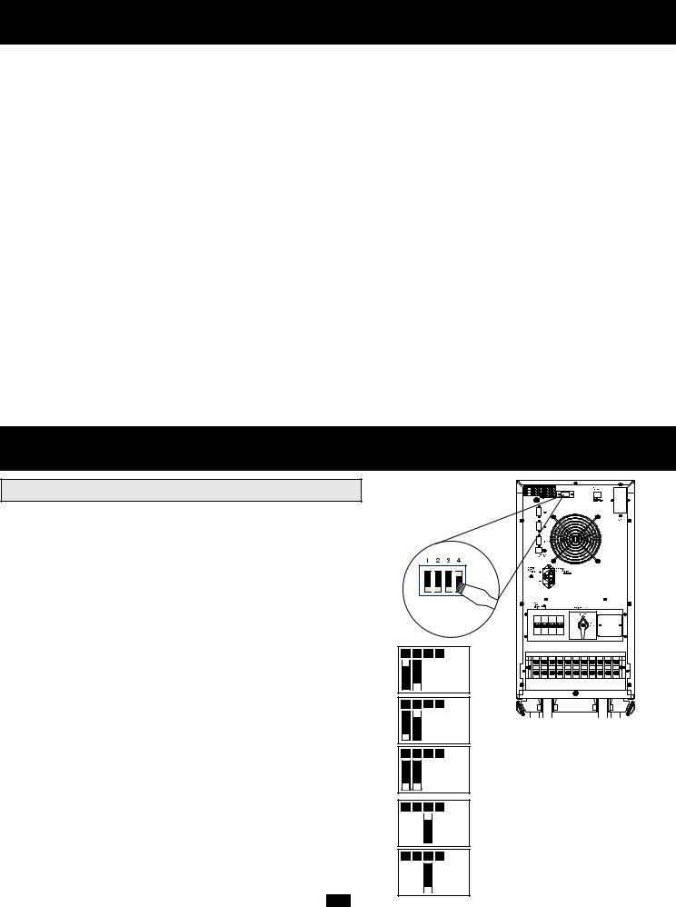
INVERTER OPERATION DIP SWITCH SETTINGS
Using a small tool, set the four Inverter Operation DIP Switches (located on the rear panel of your UPS) to match your input voltage, input frequency and desired operational mode.
Input Voltage Selection
(DIP Switches #1 & #2)
These DIP switches must be set to match your input voltage. Your UPS WILL NOT CONVERT the voltage.
Input Voltage |
DIP Switch Position |
|
|
220V |
#1 UP & #2 DOWN |
|
|
230V |
#1 DOWN & #2 UP |
|
|
240V |
#1 DOWN & #2 DOWN |
|
|
Input Frequency Selection
(DIP Switch #3)
Your Input Frequency setting MUST match your input frequency. Your UPS WILL NOT CONVERT the frequency.
Input Frequency |
DIP Switch Position |
|
|
50 Hz |
#3 UP |
|
|
60 Hz |
#3 DOWN |
|
|
1 |
2 |
3 |
4 |
|
|
|
220V |
1 |
2 |
3 |
4 |
230V
1 2 3 4
240V
1 2 3 4
50 Hz
1 2 3 4
60 Hz
REFER TO USER'S MANUAL FOR TORQUING SPECIFICATIONS, USE COPPER CONDUCTORS ONLY. UTILISER SEULEMENT LES CONDUCTEURS DE CUIVRE.
5

Installation (continued)
Operational Mode Selection
(DIP Switch #4)
The "On-Line" Mode provides on-line operation with zero transfer time. The "Economy" Mode provides line-interactive operation for increased efficiency when on-line protection is unnecessary, thus reducing operating costs without affecting your UPS's output reliability during a power outage.
|
|
|
1 |
|
2 |
|
3 |
|
4 |
|
|
||
|
|
|
|
|
|
|
|
|
|
|
|
|
|
Operational Mode |
DIP Switch Position |
|
|
|
|
|
|
|
|
|
|
|
|
|
|
|
|
|
|
|
|
|
|
|
|
On-Line |
|
On-Line |
#4 UP |
|
|
|
|
|
|
|
|
|
|
||
|
|
|
|
|
|
|
|
|
|||||
|
|
|
|
|
|
|
|
|
|
|
|||
|
|
|
|
1 |
|
2 |
|
3 |
|
4 |
|
|
|
Economy |
#4 DOWN |
Economy |
|||||||||||
|
|
|
|
|
|
|
|
|
|
||||
|
|
|
|
|
|
|
|
|
|
||||
|
|
|
|
|
|
|
|
|
|
|
|
||
|
|
|
|
|
|
|
|
|
|
|
|
||
|
|
|
|
|
|
|
|
|
|
|
|
||
UPS LOCATION
Move your UPS over short distances using its wheels. Stabilize the UPS by releasing the stabilizers on each side of the unit. NOTE: Do not stack the UPS System power module or external battery modules.
INPUT AND OUTPUT CONNECTION
WIRING SELECTION
Choose appropriate cabling (cabling should have a temperature rating of 70° C and 6 AWG size) to connect your UPS to an AC power supply and your equipment to your UPS.
WIRING CONNECTIONS
Connect your wiring to the input and output terminal blocks located on the lower rear panel of your UPS (see figure below).
CAUTION!
Qualified personnel should follow all procedures prescribed by N.E.C. and other local codes for hardwiring devices to a utility source. Ensure that cables are fitted with cable sleeves and are secured by connector clamps. Tighten connections with a torque of not less than 35 inch-pounds.
NOTE: when shipped from the factory, bypass input and main R phase terminals are shorted together.
CAUTION: Observe the appropriate cable connection regulations [e.g. National Electrical Code (NEC) in the U.S.] at all times. Using cables of improper size may damage your equipment and cause fire hazards. Ground the UPS and the load equipment as shown in the figure.
6

Installation (continued)
EXTERNAL BATTERY MODULE CONNECTION (required)
Connect the battery module to the power module. Consult the owner's manual that came with your battery module. Fully insert the connector on the end of the battery module's cable into the connector on the rear panel of the power module. Small sparks may occur; this is normal. NOTE: the power module does not contain internal batteries and will not start until a battery module is connected. The battery modules are fully charged prior to shipping. However, before expecting full backup capability (particularly if the battery module has been stored for an extended period) after the UPS system is connected to a utility power source, allow the battery module to recharge for 12 hours. Once the UPS system is in use, it will charge the batteries and maintain the charge level automatically. If needed, connect additional battery modules in a daisy-chain with each module's cable inserted into the previous module's connector.
REFER TO USER'S MANUAL FOR TORQUING
SPECIFICATIONS, USE COPPER CONDUCTORS ONLY.
UTILISER SEULEMENT LES CONDUCTEURS DE CUIVRE.
Battery Module |
Power Module |
Rear Panel |
Rear Panel |
BATTERY CONDITION VERIFICATION
When the UPS is operating from battery power, the alarm and LCD Display will both alert you to the UPS battery’s charge condition.
Battery Charge Condition |
Alarm |
LCD Display |
|
|
|
FULL |
Short Beep (every 2 seconds) |
ON BATTERY |
|
|
BATT = XXV XX% |
|
|
|
LOW |
Short Beep (every 1/2 second) |
BATTERY LOW |
|
|
BATT = XXV XX% |
|
|
|
UNDER |
Continuous Beep |
BATTERY UNDER |
|
|
SHUT DOWN |
|
|
|
7

Operation (Normal Conditions)
TURNING THE UPS ON
•Make sure the UPS is properly installed (see Installation section) and the Manual Bypass Key is set to NORMAL.
•Turn the AC Input and Bypass AC Input Circuit Breakers ON.
•If your AC input is providing power normally within your selected range (see Input Voltage Selection, and Specifications), your connected load will energize. However, the UPS's inverter is not yet on. Press the front "ON/OFF" switch ON to begin inverter operation.
•If your AC input is not providing power normally, you have the option of starting from battery. (Your battery must be at least partially charged for this operation to succeed.) Press and hold both the "Battery Start" switch and the "ON/OFF" switch for three seconds to start your UPS in "ON BATTERY" mode. Note that some electronic equipment may draw more amps during startup; when starting from battery, consider reducing the initial load on the UPS.
•The UPS will perform a brief self-test and show the results on the LCD Display. (See Self-Test section, for display sequence.) After a successful self-test, the UPS will provide AC power from the inverter to your load.
TURNING THE UPS OFF
•Press the front “ON/OFF” Switch OFF. Your load will still be energized. The inverter is now off, but your UPS is not fully deactivated. The LCD Display will show “ON BYPASS."
•Turn the AC Input and Bypass AC Input Circuit Breakers OFF. Your load will no longer be energized, and the LCD display will be dark.
8
Operation (Normal Conditions) (continued)
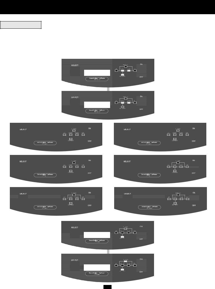
SELF-TESTING
When you turn the UPS ON, it will perform a brief (about 25 second) self-test. See figure below for display sequence.*
*Note: If starting from battery, the BATTERY LED will be lit and the I/P and BYPASS LEDs will not. The final LCD display in the diagram below appears when the UPS is operating normally under utility-supplied AC input power.
FREQ OUT = XXHz
AC INPUT OK!
|
|
|
|
|
|
|
|
|
|
|
|
|
|
|
|
|
|
|
|
|
|
|
|
|
|
|
|
|
|
|
|
|
|
|
|
|
|
|
|
|
|
|
|
|
|
|
|
|
|
|
|
|
|
|
|
|
|
|
|
|
|
|
|
|
|
|
|
|
|
|
|
|
|
|
|
|
|
|
|
|
|
|
|
|
|
|
|
|
|
|
|
|
|
|
|
|
|
|
|
|
|
|
|
|
|
|
|
|
|
|
|
|
|
|
|
|
|
|
|
|
|
|
|
|
|
|
|
|
|
|
|
|
|
|
|
|
|
|
|
|
|
|
|
|
|
|
|
|
|
|
|
|
|
|
|
|
|
|
|
|
|
|
|
|
|
|
|
|
|
|
|
|
|
|
|
|
|
|
|
|
|
|
|
|
|
|
|
|
|
|
|
|
|
|
|
|
|
|
|
|
|
|
|
|
|
|
|
|
|
|
|
|
|
|
|
|
|
|
|
|
|
|
|
|
|
|
|
|
|
|
|
|
|
|
|
|
|
|
|
|
|
|
|
|
|
|
|
|
|
|
|
|
|
|
|
|
|
|
|
|
|
|
|
|
|
|
|
|
|
|
|
|
|
|
|
|
|
|
|
|
|
|
|
|
|
|
|
|
|
|
|
|
|
|
|
|
|
|
|
|
|
|
|
|
|
|
|
|
|
|
|
|
|
|
|
|
|
|
|
|
|
|
|
|
|
|
|
|
|
|
|
|
|
|
|
|
|
|
|
|
|
|
|
|
|
|
|
|
|
|
|
|
|
|
|
|
|
|
|
|
|
|
|
|
|
|
|
|
|
|
|
|
|
|
|
|
|
|
|
|
|
|
|
|
|
|
|
|
|
|
|
|
|
|
|
|
|
|
|
|
|
|
|
|
|
|
|
|
|
|
|
|
|
|
|
|
|
|
|
|
|
|
|
|
|
|
|
|
|
|
|
|
|
|
|
|
|
|
|
|
|
|
|
|
|
|
|
|
|
|
|
|
|
|
|
|
|
|
|
|
|
|
|
|
|
|
|
|
|
|
|
|
|
|
|
|
|
|
|
|
|
|
|
|
|
|
|
|
|
|
|
|
|
|
|
|
|
|
|
|
|
|
|
|
|
|
|
|
|
|
|
|
|
|
|
|
|
|
|
|
|
|
|
|
|
|
|
|
|
|
|
|
|
|
|
|
|
|
|
|
|
|
|
|
|
|
|
|
|
|
|
|
|
|
|
|
|
|
|
|
|
|
|
|
|
|
|
|
|
|
|
|
|
|
|
|
|
|
|
|
|
|
|
|
|
|
|
|
|
|
|
|
|
|
|
|
|
|
|
|
|
|
|
|
|
|
OR |
|
|
|
|
|
|
|
|
|
|
|
|
|
|
|
|
|
|
|
|
|
|
|
|
|
|||
|
|
|
|
|
|
|
|
|
|
|
|
|
|
|
|
|
|
|
|
|
|
|
|
|
|
|
|
|
|
|
|
|
|
|
|
|
|
|
|
|
|
|
|
|
|
|
|
|||||
|
|
|
|
|
|
|
|
|
|
|
|
|
|
|
|
|
|
|
|
|
|
|
|
|
|
|
|
|
|
|
|
|
|
|||||||||||||||||||
|
|
|
|
|
|
|
|
|
|
|
|
|
|
|
|
|
|
|
|
|
|
|
|
|
|
|
|
|
|
|
|
|
|
|
|
|
|
|
|
|
|
|||||||||||
|
|
|
BATTERY OK! |
|
|
|
|
|
|
|
|
|
|
|
|
|
|
|
|
|
|
|
|
|
|
|
|
|
|
|
|
|
BATTERY FAILURE! |
|
|
|
|
|
|
|
|
|
|
|
|
|
|
|||||
|
|
|
|
|
|
|
|
|
|
|
|
|
|
|
|
|
|
|
|
|
|
|
|
|
|
|
|
|
|
|
|
|
|
|
|
|
|
|
|
|
|
|
|
|
|
|||||||
|
|
|
|
|
|
|
|
|
|
|
|
|
|
|
|
|
|
|
|
|
|
|
|
|
|
|
|
|
|
|
|
|
|
|
|
|
|
|
|
|
|
|
|
|
|
|
|
|
|
|
|
|
|
|
|
|
|
|
|
|
|
|
|
|
|
|
|
|
|
|
|
|
|
|
|
|
|
|
|
|
|
|
|
|
|
|
|
|
|
|
|
|
|
|
|
|
|
|
|
|
|
|
|
|
|
|
|
|
|
|
|
|
|
|
|
|
|
|
|
|
|
|
|
|
|
|
|
|
|
|
|
|
|
|
|
|
|
|
|
|
|
|
|
|
|
|
|
|
|
|
|
|
|
|
|
|
|
|
|
|
|
|
|
|
|
|
|
|
|
|
|
|
|
|
|
|
|
|
|
|
|
|
|
|
|
|
|
|
|
|
|
|
|
|
|
|
|
|
|
|
|
|
|
|
|
|
|
|
|
|
|
|
|
|
|
|
|
|
|
|
|
|
|
|
|
|
|
|
|
|
|
|
|
|
|
|
|
|
|
|
|
|
|
|
|
|
|
|
|
|
|
|
|
|
|
|
|
|
|
|
|
|
|
|
|
|
|
|
|
|
|
|
|
|
|
|
|
|
|
|
|
|
|
|
|
|
|
|
|
|
|
|
|
|
|
|
|
|
|
|
|
|
|
|
|
|
|
|
|
|
|
|
|
|
|
|
|
|
|
|
|
|
|
|
|
|
|
|
|
|
|
|
|
|
|
|
|
|
|
|
|
|
|
|
|
|
|
|
|
|
|
|
|
|
|
|
|
|
|
|
|
|
|
|
|
|
|
|
|
|
|
|
|
|
|
|
|
|
|
|
|
|
|
|
|
|
|
|
|
|
|
|
|
|
|
|
|
|
|
|
|
|
|
|
|
|
|
|
|
|
|
|
|
|
|
|
|
|
|
|
|
|
|
|
|
|
|
|
|
|
|
|
|
|
|
|
|
|
|
|
|
|
|
|
|
|
|
|
|
|
|
|
|
|
|
|
|
|
|
|
|
|
|
|
|
|
|
|
|
|
|
|
|
|
|
|
|
|
|
|
|
|
|
|
|
|
|
|
|
|
|
|
|
|
|
|
|
|
|
|
|
|
|
|
|
|
|
|
|
|
|
|
|
|
|
|
|
|
|
|
|
|
|
|
|
|
|
|
|
|
|
|
|
|
|
|
|
|
|
|
|
|
|
|
|
|
|
|
|
|
|
|
|
|
|
|
|
|
|
|
|
|
|
|
|
|
|
|
|
|
|
|
|
|
|
|
|
|
|
|
|
|
|
|
|
|
|
|
|
|
|
|
|
|
|
|
|
|
|
|
|
|
|
|
|
|
|
|
|
|
|
|
|
|
|
|
|
|
|
|
|
|
|
|
|
|
|
|
|
|
|
|
|
|
|
|
|
|
|
|
|
|
|
|
|
|
|
|
|
|
|
|
|
|
|
|
|
|
|
|
|
|
|
|
|
|
|
|
|
|
|
|
|
|
|
|
|
|
|
|
|
|
|
|
|
|
|
|
|
|
|
|
|
|
|
|
|
|
|
|
|
|
|
|
|
|
|
|
|
|
|
|
|
|
|
|
|
|
|
|
|
|
|
|
|
|
|
|
|
|
|
|
|
|
|
|
|
|
|
|
|
|
|
|
|
|
|
|
|
|
|
|
|
|
|
|
|
|
|
|
|
|
|
|
|
|
|
|
|
|
|
|
|
|
|
|
|
|
|
|
|
|
|
|
|
|
|
|
|
|
|
|
|
|
|
|
|
|
|
|
|
|
|
|
|
|
|
|
|
|
|
|
|
|
|
|
|
|
|
|
|
|
|
|
|
|
|
|
|
|
|
|
|
|
|
|
|
|
|
|
|
|
|
|
|
|
|
|
|
|
|
|
|
|
|
|
|
|
|
|
|
|
|
|
|
|
|
|
|
|
|
|
|
|
|
|
|
|
|
|
|
|
|
|
|
|
|
|
|
|
|
|
|
|
|
|
|
|
|
|
|
|
|
|
|
|
|
|
|
|
|
|
|
|
|
|
|
|
|
|
|
|
|
|
|
|
|
|
|
|
|
|
|
|
|
|
|
|
|
|
|
|
|
|
|
|
|
|
|
|
|
|
|
|
|
|
|
|
|
|
|
|
|
|
|
|
|
|
|
|
|
|
|
|
|
|
|
|
|
|
|
|
|
|
|
|
|
|
|
|
|
|
|
|
|
|
|
|
|
|
|
|
|
|
|
|
|
|
|
|
|
|
|
|
|
|
|
|
|
|
|
|
|
|
|
|
|
|
|
|
|
|
|
|
|
|
|
|
|
|
|
|
|
|
|
|
|
|
|
|
|
|
|
|
|
|
|
|
|
|
|
|
|
|
|
|
|
|
|
|
|
|
|
|
|
|
|
|
|
|
|
|
|
|
|
|
|
|
|
|
|
|
|
|
|
|
|
|
|
|
|
|
|
|
|
|
|
|
|
|
|
|
|
|
|
|
|
|
|
|
|
|
|
|
|
|
|
|
|
|
|
|
|
|
|
|
|
|
|
|
|
|
|
|
|
|
|
|
|
|
|
|
|
|
|
|
|
|
|
|
|
|
|
|
|
|
|
|
|
|
|
|
|
|
|
|
|
|
|
|
|
|
|
|
|
OR |
|
|
|
|
|
|
|
|
|
|
|
|
|
|
|
|
|
|
|
||
|
|
|
|
|
|
|
|
|
|
|
|
|
|
|
|
|
|
|
|
|
|
|
|
|
|
|
|
|
|
|
|
|
|
|
|
|
|
|
|||
|
|
|
|
|
|
|
|
|
|
|
|
|
|
|
|
|
|
|
|
|
|
|
|
|
|
|
|
|
|
|
|
|
|
|
|
|
|
||||
|
|
|
CHARGER OK! |
|
|
|
|
|
|
|
|
|
|
|
|
|
|
|
|
|
|
|
|
|
CHARGER FAILURE! |
|
|
|
|
|
|
|
|
|
|
|
|
||||
|
|
|
|
|
|
|
|
|
|
|
|
|
|
|
|
|
|
|
|
|
|
|
|
|
|
|
|
|
|
|
|
|
|
|
|
||||||
|
|
|
|
|
|
|
|
|
|
|
|
|
|
|
|
|
|
|
|
|
|
|
|
|
|
|
|
|
|
|
|
|
|
|
|
|
|
|
|
|
|
|
|
|
|
|
|
|
|
|
|
|
|
|
|
|
|
|
|
|
|
|
|
|
|
|
|
|
|
|
|
|
|
|
|
|
|
|
|
|
|
|
|
|
|
|
|
|
|
|
|
|
|
|
|
|
|
|
|
|
|
|
|
|
|
|
|
|
|
|
|
|
|
|
|
|
|
|
|
|
|
|
|
|
|
|
|
|
|
|
|
|
|
|
|
|
|
|
|
|
|
|
|
|
|
|
|
|
|
|
|
|
|
|
|
|
|
|
|
|
|
|
|
|
|
|
|
|
|
|
|
|
|
|
|
|
|
|
|
|
|
|
|
|
|
|
|
|
|
|
|
|
|
|
|
|
|
|
|
|
|
|
|
|
|
|
|
|
|
|
|
|
|
|
|
|
|
|
|
|
|
|
|
|
|
|
|
|
|
|
|
|
|
|
|
|
|
|
|
|
|
|
|
|
|
|
|
|
|
|
|
|
|
|
|
|
|
|
|
|
|
|
|
|
|
|
|
|
|
|
|
|
|
|
|
|
|
|
|
|
|
|
|
|
|
|
|
|
|
|
|
|
|
|
|
|
|
|
|
|
|
|
|
|
|
|
|
|
|
|
|
|
|
|
|
|
|
|
|
|
|
|
|
|
|
|
|
|
|
|
|
|
|
|
|
|
|
|
|
|
|
|
|
|
|
|
|
|
|
|
|
|
|
|
|
|
|
|
|
|
|
|
|
|
|
|
|
|
|
|
|
|
|
|
|
|
|
|
|
|
|
|
|
|
|
|
|
|
|
|
|
|
|
|
|
|
|
|
|
|
|
|
|
|
|
|
|
|
|
|
|
|
|
|
|
|
|
|
|
|
|
|
|
|
|
|
|
|
|
|
|
|
|
|
|
|
|
|
|
|
|
|
|
|
|
|
|
|
|
|
|
|
|
|
|
|
|
|
|
|
|
|
|
|
|
|
|
|
|
|
|
|
|
|
|
|
|
|
|
|
|
|
|
|
|
|
|
|
|
|
|
|
|
|
|
|
|
|
|
|
|
|
|
|
|
|
|
|
|
|
|
|
|
|
|
|
|
|
|
|
|
|
|
|
|
|
|
|
|
|
|
|
|
|
|
|
|
|
|
|
|
|
|
|
|
|
|
|
|
|
|
|
|
|
|
|
|
|
|
|
|
|
|
|
|
|
|
|
|
|
|
|
|
|
|
|
|
|
|
|
|
|
|
|
|
|
|
|
|
|
|
|
|
|
|
|
|
|
|
|
|
|
|
|
|
|
|
|
|
|
|
|
|
|
|
|
|
|
|
|
|
|
|
|
|
|
|
|
|
|
|
|
|
|
|
|
|
|
|
|
|
|
|
|
|
|
|
|
|
|
|
|
|
|
|
|
|
|
|
|
|
|
|
|
|
|
|
|
|
|
|
|
|
|
|
|
|
|
|
|
|
|
|
|
|
|
|
|
|
|
|
|
|
|
|
|
|
|
|
|
|
|
|
|
|
|
|
|
|
|
|
|
|
|
|
|
|
|
|
|
|
|
|
|
|
|
|
|
|
|
|
|
|
|
|
|
|
|
|
|
|
|
|
|
|
|
|
|
|
|
|
|
|
|
|
|
|
|
|
|
|
|
|
|
|
|
|
|
|
|
|
|
|
|
|
|
|
|
|
|
|
|
|
|
|
|
|
|
|
|
|
|
|
|
|
|
|
|
|
|
|
|
|
|
|
|
|
|
|
|
|
|
|
|
|
|
|
|
|
|
|
|
|
|
|
|
|
|
|
|
|
|
|
|
|
|
|
|
|
|
|
|
|
|
|
|
|
|
|
|
|
|
|
|
|
|
|
|
|
|
|
|
|
|
|
|
|
|
|
|
|
|
|
|
|
|
|
|
|
|
|
|
|
|
|
|
|
|
|
|
|
|
|
|
|
|
|
|
|
|
|
|
|
|
|
|
|
|
|
|
|
|
|
|
|
|
|
|
|
|
|
|
|
OR
|
|
|
AC/DC OK! |
|
|
|
|
|
|
|
|
|
|
|
|
|
|
|
|
|
|
|
|
|
|
AC/DC FAILURE! |
|
|
|
|
|
|
|
|
|
|
|||||
|
|
|
|
|
|
|
|
|
|
|
|
|
|
|
|
|
|
|
|
|
|
|
|
|
|
|
|
|
|
|
|
|
|
|
|||||||
|
|
|
|
|
|
|
|
|
|
|
|
|
|
|
|
|
|
|
|
|
|
|
|
|
|
|
|
|
|||||||||||||
|
|
|
|
|
|
|
|
|
|
|
|
|
|
|
|
|
|
|
|
|
|
|
|
|
|
|
|
|
|
|
|
|
|
|
|
|
|
|
|
|
|
|
|
|
|
|
|
|
|
|
|
|
|
|
|
|
|
|
|
|
|
|
|
|
|
|
|
|
|
|
|
|
|
|
|
|
|
|
|
|
|
|
|
|
|
|
|
|
|
|
|
|
|
|
|
|
|
|
|
|
|
|
|
|
|
|
|
|
|
|
|
|
|
|
|
|
|
|
|
|
|
|
|
|
|
|
|
|
|
|
|
|
|
|
|
|
|
|
|
|
|
|
|
|
|
|
|
|
|
|
|
|
|
|
|
|
|
|
|
|
|
|
|
|
|
|
|
|
|
|
|
|
|
|
|
|
|
|
|
|
|
|
|
|
|
|
|
|
|
|
|
|
|
|
|
|
|
|
|
|
|
|
|
|
|
|
|
|
|
|
|
|
|
|
|
|
|
|
|
|
|
|
|
|
|
|
|
|
|
|
|
|
|
|
|
|
|
|
|
|
|
|
|
|
|
|
|
|
|
|
|
|
|
|
|
|
|
|
|
|
|
|
|
|
|
|
|
|
|
|
|
|
|
|
|
|
|
|
|
|
|
|
|
|
|
|
|
|
|
|
|
|
|
|
|
|
|
|
|
|
|
|
|
|
|
|
|
|
|
|
|
|
|
|
|
|
|
|
|
|
|
|
|
|
|
|
|
|
|
|
|
|
|
|
|
|
|
|
|
|
|
|
|
|
|
|
|
|
|
|
|
|
|
|
|
|
|
|
|
|
|
|
|
|
|
|
|
|
|
|
|
|
|
|
|
|
|
|
|
|
|
|
|
|
|
|
|
|
|
|
|
|
|
|
|
|
|
|
|
|
|
|
|
|
|
|
|
|
|
|
|
|
|
|
|
|
|
|
|
|
|
|
|
|
|
|
|
|
|
|
|
|
|
|
|
|
|
|
|
|
|
|
|
|
|
|
|
|
|
|
|
|
|
|
|
|
|
|
|
|
|
|
|
|
|
|
|
|
|
|
|
|
|
|
|
|
|
|
|
|
|
|
|
|
|
|
|
|
|
|
|
|
|
|
|
|
|
|
|
|
|
|
|
|
|
|
|
|
|
|
|
|
|
|
|
|
|
|
|
|
|
|
|
|
|
|
|
|
|
|
|
|
|
|
|
|
|
|
|
|
|
|
|
|
|
|
|
|
|
|
|
|
|
|
|
|
|
|
|
|
|
|
|
|
|
|
|
|
|
|
|
|
|
|
|
|
|
|
|
|
|
|
|
|
|
|
|
|
|
|
|
|
|
|
|
|
|
|
|
|
|
|
|
|
|
|
|
|
|
|
|
|
|
|
|
|
|
|
|
|
|
|
|
|
|
|
|
|
|
|
|
|
|
|
|
|
|
|
|
|
|
|
|
|
|
|
|
|
|
|
|
|
|
|
|
|
|
|
|
|
|
|
|
|
|
|
|
|
|
|
|
|
|
|
|
|
|
|
|
|
|
|
|
|
|
|
|
|
|
|
|
|
|
|
|
|
|
|
|
|
|
|
|
|
|
|
|
|
|
|
|
|
|
|
|
|
|
|
|
|
|
|
|
|
|
|
|
|
|
|
|
|
|
|
|
|
|
|
|
|
|
|
|
|
|
|
|
|
|
|
|
|
|
|
|
 WAIT!
WAIT!
TESTING INVERTER
 ON INVERTER
 LOAD = XXX% X.XXKW
9

Operation (Normal Conditions) (continued)
LCD DISPLAY SELECT SWITCH
Momentarily press the “SELECT” switch on the front panel to browse through different power readings on the LCD Display. The LCD Display will show which one of four operational modes your UPS is currently in: Normal, Economy, On-Battery, or Bypass. Also, as you press the “SELECT” switch, the LCD Display will browse through load, input, bypass, output and battery conditions.
"NORMAL" MODE OPERATION |
"ON-BATTERY" MODE OPERATION |
||||||||
|
|
|
|
|
|
|
|
|
|
|
|
|
|
|
|
|
|
|
|
|
|
|
|
|
|
|
|
|
|
|
|
ON INVERTER |
|
|
|
ON BATTERY |
|
||
|
|
LOAD = XXX% X.XXKW |
|
|
|
LOAD = XXX% X.XXKW |
|
||
|
|
|
|
|
|
|
|
|
|
|
|
|
PRESS SELECT KEY |
|
|
|
PRESS SELECT KEY |
||
|
|
|
|
|
|
|
|
|
|
|
|
ON INVERTER |
|
|
|
ON BATTERY |
|
||
|
|
IN R = XXXV XX.XHz |
|
|
|
IN R = XXXV XX.XHz |
|
||
|
|
|
|
|
|
|
|
|
|
|
|
|
PRESS SELECT KEY |
|
|
|
PRESS SELECT KEY |
||
|
|
|
|
|
|
|
|
||
|
|
ON INVERTER |
|
|
|
ON BATTERY |
|
||
|
|
IN S = XXXV T=XXXV |
|
|
|
IN S = XXXV T=XXXV |
|
||
|
|
|
|
|
|
|
|
|
|
|
|
|
PRESS SELECT KEY |
|
|
|
PRESS SELECT KEY |
||
|
|
|
|
|
|
|
|
|
|
|
|
ON INVERTER |
|
|
|
ON BATTERY |
|
||
|
|
OUT = XXXV XX.XHz |
|
|
|
OUT = XXXV XX.XHz |
|
||
|
|
|
|
|
|
|
|
|
|
|
|
|
PRESS SELECT KEY |
|
|
|
PRESS SELECT KEY |
||
|
|
|
|
|
|
|
|
|
|
|
|
ON INVERTER |
|
|
|
ON BATTERY |
|
||
|
|
BATT = XXXV XXX% |
|
|
|
BATT = XXXV XXX% |
|
||
|
|
|
|
|
|
|
|
|
|
|
|
|
PRESS SELECT KEY |
|
|
|
PRESS SELECT KEY |
||
|
|
|
|
|
|
||||
|
|
|
|
|
|
|
|
|
|
|
|
|
|
|
|
|
|
|
|
"ECONOMY" MODE OPERATION |
"ON BYPASS" MODE OPERATION |
||||||||
|
|
|
|
|
|
||||
|
|
|
|
|
|
|
|
|
|
|
|
|
|
|
|
|
|
|
|
|
|
ECONOMY MODE |
|
|
|
ON BYPASS |
|
||
|
|
LOAD = XXX% X.XXKW |
|
|
|
LOAD = XXX% X.XXKW |
|
||
|
|
|
|
|
|
|
|
|
|
|
|
|
PRESS SELECT KEY |
|
|
|
PRESS SELECT KEY |
||
|
|
ECONOMY MODE |
|
|
|
ON BYPASS |
|
||
|
|
IN R = XXXV XX.XHz |
|
|
|
BYPS = XXXV XX.XHz |
|
||
|
|
|
|
|
|
|
|
|
|
|
|
|
PRESS SELECT KEY |
|
|
|
PRESS SELECT KEY |
||
|
|
|
|
|
|
||||
|
|
ECONOMY MODE |
|
|
|
ON BYPASS |
|
||
|
|
IN S = XXXV T=XXXV |
|
|
|
OUT = XXXV XXX% |
|
||
|
|
|
|
|
|
|
|
|
|
|
|
|
PRESS SELECT KEY |
|
|
|
PRESS SELECT KEY |
||
|
|
|
|
|
|
|
|
|
|
|
|
ECONOMY MODE |
|
|
|
|
|
|
|
|
|
OUT = XXXV XX.XHz |
|
|
|
|
|
|
|
|
|
|
|
|
|
|
|
|
|
|
|
|
PRESS SELECT KEY |
|
|
|
|
|
|
|
|
|
|
|
|
|
|
|
|
|
|
ECONOMY MODE |
|
|
|
|
|
|
|
|
|
BATT = XXXV XXX% |
|
|
|
|
|
|
|
|
|
|
|
|
|
|
|
|
|
|
|
|
PRESS SELECT KEY |
|
|
|
|
|
|
|
|
|
|
|
|
|
|
||
|
|
|
|
|
|
|
|
|
|
Operation (Special Conditions)
OPERATION ON BYPASS—VOLTAGE OUT OF RANGE
While in Bypass Mode, the UPS monitors the input voltage, which on Bypass equals the output voltage. If the output voltage passes out of an acceptable range (between 15% higher and 20% lower than nominal), the UPS displays the condition on its LCD and stops supplying output power to its load. If power levels return to an acceptable level, the UPS resumes supplying power to the load, and its LCD reports that output voltage was too high or too low at one time, but has returned to nominal.
Bypass Voltage Condition |
LCD Display Message |
|
|
>15% Higher than Nominal |
BYPASS HI NO O/P |
|
|
>20% Lower than Nominal |
BYPASS LO NO O/P |
|
|
Was Too High, Now Nominal |
BYPASS WAS HI |
|
|
Was Too Low, Now Nominal |
BYPASS WAS LO |
|
|
10
Operation (Special Conditions) (continued)
OPERATION ON OVERLOAD
When the UPS detects an output overload, it will commence a countdown (the length of time depending on the severity of the overload). If the UPS is still overloaded at the end of the countdown, the UPS will automatically shut down and go into Bypass Mode.
Overload Condition |
LCD Display Message |
Countdown to Shutdown |
|
|
|
102% - 125% |
OVERLOAD 102% |
1 minute |
|
LOAD=XXX% X.XXKW |
|
|
|
|
125% - 150% |
OVERLOAD 125% |
30 seconds |
|
LOAD=XXX% X.XXKW |
|
|
|
|
>150% |
OVERLOAD 150% |
2 seconds |
|
LOAD=XXX% X.XXKW |
|
|
|
|
BATTERY CHARGE WARNINGS
Since your UPS can provide battery backup only for as long as the batteries remain charged, these warnings should be acted on immediately.
Battery Charge Warning |
LCD Display Message |
|
|
Battery charge nearly depleted |
BATTERY LOW |
|
|
Low battery shutdown |
LOW BATTERY! SHUT DOWN… |
|
|
OPERATION UNDER SHUTDOWN
Your UPS will shut down and the LCD will display a message if it detects one of the following conditions. Note: For all conditions, the “Input,” “Output” and “Bypass” LEDs will be illuminated.
Condition |
LCD Display Message |
|
|
Extended Overload (>150%) |
OVERLOAD XX% |
|
SHUT DOWN… |
|
|
Output Short Circuit |
SHORT CIRCUIT! |
|
SHUT DOWN… |
|
|
Remote Shutdown Command |
REMOTE |
(from DB9 interface) |
SHUT DOWN… |
|
|
Remote Shutdown Command |
EMERGENCY STOP! |
(from RJ11 interface) |
SHUT DOWN… |
|
|
Internal Faults |
INVERTER TOO LO |
|
SHUT DOWN… |
|
|
|
INVERTER TOO HI |
|
SHUT DOWN… |
|
|
|
DC BUS +/- HIGH/LOW |
|
SHUT DOWN… |
|
|
|
OVER TEMPERATURE |
|
SHUT DOWN… |
|
|
11

Operation (Special Conditions) (continued)
OPERATION OF MANUAL BYPASS SWITCH
Turn this switch to “BYPASS” before performing any maintenance on the UPS with the connected load supported. Connected equipment will receive filtered AC mains power, but will not receive battery power in the event of a blackout.
SWITCHING UPS TO “BYPASS” MODE
•Turn the “ON/OFF” Switch OFF. (LCD will read "ON BYPASS.")
•Turn the “Manual Bypass” Switch clockwise from NORMAL to BYPASS.
•Turn the AC Input Circuit Breaker OFF.
SWITCHING UPS TO “NORMAL” MODE
•Turn the AC Input Circuit Breaker ON.
•Turn the “Manual Bypass” Switch counterclockwise from BYPASS back to NORMAL.
•Turn the “ON/OFF” Switch ON.
Communications
RS-232 INTERFACE
This female DB9 port connects your UPS via an RS-232 cable to a workstation or server equipped with Tripp Lite software. The port uses RS-232 communications to report UPS status and power conditions. Using this port, Tripp Lite software can monitor and manage network power and automatically save open files and shut down equipment during a blackout. Contact Tripp Lite Customer Support at (773) 8691234 for information on available SNMP, network management and connectivity software and products.
RS-232 signals and operations include: load level, battery status, battery level, operation mode, AC input voltage, AC output voltage, AC input frequency, temperature inside unit, set shut-down delay time, enable/disable alarm and remote shutdown.
Hardware: |
|
Baud Rate: |
2400 BPS |
Data Length: |
8 bits |
Stop Bit: |
1 bit |
Parity: |
NONE |
Pin assignment:
Pin 2: TXD (Transmit Data)
Pin 3: RXD (Receive Data)
Pin 5: GND (Signal Ground)
12

Communications (continued)
AS-400 INTERFACE
This female DB9 port connects your UPS to an IBM AS-400 computer via the included AS-400 cable. The port uses AS-400 communications to report UPS status. It can be used to allow an AS-400 to automatically save open files and shut down its operating system during a blackout. AS-400 protocol includes: operation on inverter, operation on AC power supply, operation on battery and low battery alarm.
Pin assignment: |
|
|
|
|
|
|
||
Pin 5: |
Common |
|
|
|
|
|
|
|
Pin 6: |
Operation on AC power supply |
|
|
|
|
|||
|
|
|
|
|||||
Pin 7: Low battery alarm |
|
|
|
|
|
|
||
Pin 8: Operation on inverter |
|
|
|
|
||||
Pin 9: Operation on battery |
|
|
|
|
||||
AS-400 INTERFACE TABLE |
|
|
|
|
||||
|
|
|
|
|
|
|
|
|
|
|
|
Pin 6,5 |
|
Pin 7,5 |
Pin 8,5 |
Pin 9,5 |
|
|
|
|
|
|
|
|
|
|
Battery |
|
|
OFF |
|
* |
ON |
ON |
|
|
|
|
|
|
|
|
||
Low Battery |
|
OFF |
|
ON |
ON |
ON |
||
|
|
|
|
|
|
|
||
Direct Mains Supply |
|
ON |
|
OFF |
OFF |
OFF |
||
|
|
|
|
|
|
|
|
|
Inverter |
|
|
OFF |
|
* |
ON |
* |
|
|
|
|
|
|
|
|
|
|
* Inactive: may be in either state.
DRY CONTACT INTERFACE
This female DB9 contact-closure port allows your UPS to |
Pin assignment: |
||
send contact-closure signals to indicate that it is on battery |
|
||
back-up mode and if its batteries are running low. The port |
|
||
can also receive a remote shutdown signal. |
|
||
DRY CONTACT INTERFACE TABLE |
|
||
UPS Operating |
Pin 8,3 |
Pin 1,3 |
|
Mode |
|
|
|
Normal |
OPEN |
OPEN |
+- 3 V |
Back Up |
CLOSE |
* |
|
Low Battery |
CLOSE |
CLOSE |
|
* Inactive: may be in either state.
13

Communications (continued)
REMOTE EMERGENCY POWER OFF (EPO)
This optional feature is only for those applications which require connection to a facility's Emergency Power Off (EPO)circuit. When the power module is connected to this circuit, it enables emergency shutdown of the output. Using the included cable, connect the power module's EPO port to a user-supplied remote switch. The pin assignments for the EPO port are shown in the following diagram. Note: if there is a short between pins 2 and 3, 2 and 5, 4 and 5, or 3 and 4, the UPS system will power off.
Pin assignment:
Service
Your SmartOnline UPS is covered by the 2-year limited warranty period described below. A variety of service contracts is also available from Tripp Lite, including start-up service contracts and 3- to 5-year SafeSure on-site service contracts. For more information, call Tripp Lite Customer Service at (773) 869-1234.
Warranty
2-Year Limited Warranty
TRIPP LITE warrants its products including batteries to be free from defects in materials and workmanship for a period of two years from the date of initial purchase. After 90 days from the date of purchase, TRIPP LITE’s obligation under this warranty is limited to replacing parts on such defective products. To obtain service under this warranty, you must call TRIPP LITE or an authorized TRIPP LITE service center. Products must be returned to TRIPP LITE or an authorized TRIPP LITE service center with transportation charges prepaid and must be accompanied by a brief description of the problem encountered and proof of date and place of purchase. This warranty does not apply to equipment which has been damaged by accident, negligence or misapplication or has been altered or modified in any way. This warranty applies only to the original purchaser who must have properly registered the product within 10 days of purchase.
The warranties of all TRIPP LITE surge suppressors are null and void if they have been connected to the output of any UPS system. The warranties of all TRIPP LITE UPS Systems are null and void if a surge suppressor has been connected to its output receptacles.
EXCEPT AS PROVIDED HEREIN, TRIPP LITE MAKES NO WARRANTIES, EXPRESS OR IMPLIED, INCLUDING WARRANTIES OF MERCHANTABILITY AND FITNESS FOR A PARTICULAR PURPOSE. Some states do not permit limitation or exclusion of implied warranties; therefore, the aforesaid limitation(s) or exclusion(s) may not apply to the purchaser.
EXCEPT AS PROVIDED ABOVE, IN NO EVENT WILL TRIPP LITE BE LIABLE FOR DIRECT, INDIRECT, SPECIAL, INCIDENTAL OR CONSEQUENTIAL DAMAGES ARISING OUT OF THE USE OF THIS PRODUCT, EVEN IF ADVISED OF THE POSSIBILITY OF SUCH DAMAGE. Specifically, TRIPP LITE is not liable for any costs, such as lost profits or revenue, loss of equipment, loss of use of equipment, loss of software, loss of data, costs of substitutes, claims by third parties, or otherwise.
The policy of TRIPP LITE is one of continuous improvement. Specifications are subject to change without notice.
14

Specifications
The specifications listed below are for Tripp Lite model SU10K3/1X which includes two modules: a power module and a battery module. The two modules are also sold separately with their own individual model numbers: power module (individual model #: SU10K3/1INTPM) and battery module (individual model #: BP240V10RT3U).
Model: SU10K3/1X |
|
Includes: • Power Module |
• Battery Module |
Model: SU10K3/1INTPM |
Model: BP240V10RT3U |
Series: AGPS4984 |
Series: AGBP240V7RT3U |
|
|
Input |
|
Input Voltage |
270-485V, Y, 3Ø4W |
Input Frequency |
50/60 Hz ± 3 Hz (selectable) |
Input Current |
15A |
Inrush Current |
<200A |
Power Factor (Full Load) |
>0.95 |
Efficiency (Full Load/On-Line) |
>90% |
Circuit Breakers |
32A 3 pole (AC Input Breaker), 63A 1 pole (Bypass AC Input Breaker) |
|
|
Output |
|
VA |
10000 |
Watts (Power Factor: 0.8) |
8000 |
Waveform (On-Line) |
Sinewave |
Waveform (On-Battery) |
Sinewave |
Output Voltage (RMS) |
220/230/240V AC 1Ø2W |
Output Frequency |
50/60 Hz (± 0.2 Hz on battery) |
Voltage Regulation |
±2% |
Max. Harmonic Distortion (Non-Linear Full Load) |
<3% |
Overload Capabilities |
<102% (continuous), 102%~125% (1 min.), 125%~150% (30 sec.), >150% (2 sec.) |
Short Circuit Capability |
>160A |
Crest Factor |
3:1 |
|
|
Battery |
|
Battery Type |
12V/9 AH |
Battery Quantity |
20 |
Protection |
2x 30A/600V fuse |
Typical Backup Time (Full Load) |
6+ min. |
Typical Backup Time (Half Load) |
18+ min. |
|
|
Operation |
|
On-Line Transfer Time (Line to Battery, Battery to Line) |
0 ms |
Audible Noise (Full Load @ 1 meter) |
<55 dBA |
|
|
Indicators |
|
|
|
Includes an LCD Display and LEDs (AC Line In, AC to DC, DC to AC, AC Output, Battery Back-Up, Bypass).
Communications
Includes an RS-232 DB9 female connector, an AS-400 DB9 female connector, a dry contact DB9 female connector and an accessory slot.
Connections
Input Terminal Block |
60A |
Output Terminal Block |
60A |
|
|
Physical Specifications |
|
Power Module Dimensions (H x W x D): |
56.5 x 28 x 63 cm (22.2 x 11 x 24.8 in) |
Power Module Shipping Weight: |
46 kg (101.3 lb) |
Battery Module Dimensions (H x W x D): |
44.5 x 13.3 x 57.2 cm (17.5 x 5.25 x 22.5 in) |
Battery Module Shipping Weight: |
86 kg (189.6 lb) |
+ Backup times are expandable with additional Battery Modules (model: BP240V10RT3U) sold separately. The policy of Tripp Lite is one of continuous improvement. Specifications are subject to change without notice.
15

Manual del Usuario
SmartOnline™ Sistema de UPS (Torre) de Tres Fases 10kVA Inteligente Verdadero En-Línea
Entrada (Voltaje / fase): 270 - 485V C.A. / Y, 3Ø4W
Salida (Voltage/ fase): Seleccionable por el usuario 220/230/240V C.A. / 1Ø2W
Para todos los sistemas de módulos UPS (módulos de corriente eléctrica y módulos de batería) vendidos por separado o de forma combinada. Ciertos modelos selectos de sistemas de módulos UPS podrían incluir páginas de instrucciones o precauciones adicionales que deberán usarse junto con las de este manual.
|
|
|
|
|
|
|
|
|
|
|
|
|
|
|
|
|
|
|
|
Instrucciones |
17 |
|||
|
|
|||
|
|
|||
Paneles de Control |
18 |
|||
|
|
|||
|
|
|||
Paneles Posteriores |
19 |
|||
|
|
|||
|
|
|
|
|
Instalación |
20 |
|||
|
|
|||
|
|
|||
Operación (Condiciones Normales) |
23 |
|||
|
|
|||
|
|
|||
Operación (Condiciones Especiales) |
25 |
|||
|
|
|||
|
|
|||
Comunicaciones |
27 |
|||
|
|
|||
|
|
|
|
|
Servicio |
29 |
|||
|
|
|||
|
|
|||
Garantía |
29 |
|||
|
|
|||
|
|
|||
Especificaciones |
30 |
|||
|
|
|
|
|
|
|
|
|
|
English / Français / Deutsche / Русский |
1/31/46/61 |
|||
|
|
|
|
|
1111 W. 35th Street • Chicago, IL 60609 USA
(773) 869-1234 • www.tripplite.com
Copyright ©2004 Tripp Lite. Todos los derechos reservados. SmartOnline™ es una marca registrada de Tripp Lite.

Instrucciones de Seguridad Importantes
GUARDE ESTAS INSTRUCCIONES. Este manual contiene instrucciones y precauciones importantes que deberán ser seguidas durante la instalación y mantenimiento de todos los sistemas de Tres Fases UPS Tripp Lite SmartOnline y sus baterías.
Advertencias sobre el lugar de ubicación de su UPS
•Instale su UPS en el interior y lejos del calor, polvo, la luz solar directa, los sitios húmedos y otros contaminantes conductivos.
•Instale su UPS en una zona estructuralmente segura. Su UPS es extremadamente pesado, tenga cuidado cuando mueva o levante el equipo.
•Solamente opere su UPS con temperaturas interiores entre los 32° F y los 104° F (entre los 0° C y los 40° C) Se obtendrán los mejores resultados cuando se mantegan las temperaturas interiores entre los 62° F y los 84° F (entre los 17° C y los 29° C)
•Deje un espacio adecuado alrededor de cada costado de su UPS para asegurar su buena ventilación: un mínimo de 12 pulgadas (30 cm.) de distancia en la parte posterior y al menos 4 pulgadas (10 cm.) por los costados y en la parte superior.
•No instale su UPS cerca de instalaciones que contengan campos magnéticos ya que ello podría resultar en la corrupción de datos.
Advertencias sobre la conexión de su UPS
•La alimentación eléctrica para esta unidad debe ser de tres fases, clasificada de acuerdo con las especificaciones de la placa del fabricante del equipo. Asimismo deberá estar adecuadamente unida a tierra y deberá cumplir con todas las regulaciones locales requeridas para el cableado eléctrico.
Advertencias sobre la Conexión de su Equipo
•No utilice los sistemas Tripp Lite UPS para conectar sistemas de respiración artificial ya que un fallo o mal funcionamiento del sistema UPS Tripp Lite podría causar el fallo o alterar el buen funcionamiento de este tipo de aparatos.
•Conecte el terminal de tierra de su UPS a un conductor de tierra.
•El sistema UPS cuenta con su propia fuente de energía (batería) Los terminales de salidas pueden estar activos incluso cuando el UPS no esté conectado a una toma eléctrica de corriente alterna (C.A.)
Advertencias sobre la Batería
•Su UPS no requiere mantenimiento rutinario. No abra su UPS por ningún motivo. No existen elementos que deban ser mantenidos en su interior.
•Las baterías que contiene el módulo de baterías son reciclables. Refiérase a las regulaciones locales para su desecho o si se encuentra en los Estados Unidos llame al 1-800-SAV-LEAD (1-800-728-5323) para recibir información completa sobre el reciclaje. ADVERTENCIA: No bote las baterías en el fuego, el hacerlo podría causar que las baterías explotaran.
•Debido a que las baterías presentan el riesgo de choque o descarga eléctrica y operan a través de corriente de cortocircuito de alta tensión, las baterías deberán ser reemplazadas solamente por personal de servicio autorizado y observando las debidas precauciones. Consulte el manual del modulo de batería antes de proceder. Remueva relojes, anillos y demás objetos metálicos. Utilice herramientas con manillas protegidas de material aislante. Lleve guantes y botas de hule. No ponga herramientas o materiales metálicos encima de las baterías. No establezca un cortocircuito o paso sobre los terminales de las baterías con ningún objeto. Desconecte la fuente de carga antes de conectar o desconectar los terminales de las baterías. Determine si las baterías están accidentalmente unidas a tierra. Si lo están, remueva la fuente de conexión a tierra. El contacto con cualquier parte de la batería con unión a tierra puede resultar en choque o descarga eléctrica. La posibilidad de esta descarga o choque sería reducida si las uniones a tierra son eliminadas durante la instalación y mantenimiento.
•Conecte solamente cargas de batería Tripp Lite a los conectadores de batería externos de su UPS.
•No opere su UPS sin baterías.
•Los fusibles deberán ser reemplazados solamente por personal autorizado por la factoría. Los fusibles dañados deberán ser reemplazados con fusibles del mismo tipo y número.
•Siempre y cuando esta unidad esté conectada a las baterías existirá la posibilidad de voltaje con descarga mortal. La reparación y mantenimiento deberán ser realizados sólo por personal experto. Cuando se efectúe cualquier operación de reparación o mantenimiento el UPS deberá ser desconectado o fuera de servicio con derivación manual (Manual Bypass)
•Durante el recambio de baterías "en caliente" (cuando su UPS esté en derivación manual y el equipo conectado sea encendido) su UPS no proveerá corriente de respaldo proveniente de las baterías en el caso de un apagón.
•No conecte o desconecte los módulos de baterías cuando el UPS esté operando a través de baterías o cuando la unidad no esté operando con derivación manual.
17

Panel de Control
Hay dos sistemas de módulos UPS: un modulo de corriente electrica y un modulo de batería. Usted debe familiarizarse con la ubicación y funcionamiento de los distintos elementos en cada modulo antes de instalar y operar su sistema UPS. El modulo de corriente eléctrica es el único que incluye elementos con un Panel de Control frontal.
PANEL FRONTAL
SELECT |
ON |
|
|
|
OFF |
1."ON/OFF" Switch (Interruptor): Este interruptor de tecla basculante apaga y enciende el ondulador.
2."SELECT" Button (Botón de Selección): Este botón tiene dos funciones: le permite navegar a través de distintos indicadores eléctricos en el visualizador pulsando el botón de forma momentánea; tambien le permite silenciar la alarma del UPS pulsando el botón y sosteniéndolo así durante 3 segundos.
3.LCD Display (Visualizador): Este visualizador de matricial de agujas iluminado (16 x 2 caracteres) indica una amplia gama de las condiciones de operacion y datos de diagnostico del UPS. Se iluminará una vez que haya completado la instalación adecuadamente y comenzará una vez que haya encendido el interruptor.
4."I/P" (Input) LED(Detector de Entrada): Esta luz verde se iluminará de manera constante para indicar que existe un suministro constante de corriente alterna.
5."AC/DC" (Converter) LED (Convertidor de corriente C.A./C.C.): Esta luz verde se iluminará de forma constante para indicar que el convertidor de corriente alterna y continua (C.A./C.C) se encuentra activado.
6."DC/AC" (Inverter) LED (Inversor C.C./C.A.): Esta luz verde se iluminará de forma constante para indicar que el inversor C.C./C.A. del UPS se encuentra activado.
7."O/P" (Output) LED (Detector de Salida): Esta luz verde se iluminará de forma constante para indicar que su UPS está proporcionando corriente alterna (C.A.) al equipo conectado.
8."BYPASS" LED (Derivación): Esta luz verde se iluminará cuando el UPS está suministrando alimentación eléctrica filtrada sin activar su convertidor o inversor. El equipo conectado no recibiría energía por batería en el caso de un apagón.
9."BATTERY" LED (Batería): Esta luz roja se iluminará cuando el UPS esté descargando la batería para proveer corriente C.A. al equipo conectado. LA alarma sonará pero puede ser cancelada apretando y sosteniendo el botón de "SELECT" durante 3 segundos. La alarma quedará cancelada pero el indicador permanecerá iluminado.
18

Paneles Posteriores
|
7 |
|
6 |
|
8 |
|
13 |
|
15 |
|
4 |
|
18 |
17 |
12 |
|
|
|
2 |
 19
19
REFER TO USER'S MANUAL FOR TORQUING SPECIFICATIONS, USE COPPER CONDUCTORS ONLY. UTILISER SEULEMENT LES CONDUCTEURS DE CUIVRE.
14
9
10
5
11
1
3
16
Modulo de Batería Panel Posterior |
Modulo Eléctrico Panel Posterior |
1.Manual Bypass Switch (Interruptor de Desviación Manual): Este disco rojo y amarillo se usa durante el proceso de colocacion del UPS en "BYPASS", que debe de efectuarse antes de realizar cualquier tipo de mantenimiento en el UPS con el apoyo de la potencia conectada. [Véase "Operación (Condiciones Especiales)" para instrucciones paso a paso para entrar a la modalidad de "BYPASS".] Cuando el interruptor esté en "BYPASS" el equipo conectado recibirá alimentación eléctrica filtrada C.A. pero no recibiría energía por batería en el caso de un apagón.
2.Input Terminal Block (Placa de Terminales de Salida): Use estos terminales para conectar su UPS a la toma de corriente C.A. principal de entrada. Destornille y remueva la placa que los cubre para acceder a ellos.
3.Output Terminal Block (Placa de Terminales de Entrada): Use estos terminales para conectar su UPS al equipo. La placa que cubre los terminales debe ser destornillada y removida para acceder a ellos.
4.External Battery Connector (Conector de Batería Externa): Uselo para conectar el módulo de batería Tripp Lite al módulo eléctrico. Remueva la cubierta para acceder al mismo. El módulo eléctrico no funcionará sin una conexión al módulo cargado por baterías.
Refiérase al manual de usuario para módulos de baterías |
las instrucciones de conexión y advertencias de seguridad. |
5. Exhaust Fan (ventilador): Enfría y ventila el interior |
UPS. |
6. AS-400 Interface Port (Puerto Interfase AS-400): puerto DB9 hembra conecta su UPS a una una computadora interfase IBM AS400 via cable AS-400 que está incluido. Utiliza comunicaciones AS-400 para reportar el estado del UPS y las condiciones de su energía. Mediante este Puerto, una computadora IBM AS-400 puede archivos abiertos automáticamente y cerrar el sistema operativo durante un apagón. Véase "Comunicaciones" para más detalles.
7. "Smart" RS-232 Interface Port (Puerto Interfase Inteligente RS-232): Este puerto DB9 hembra conecta su UPS a una terminal de trabajo o servidor. Utiliza comunicaciones RS-232 para reportar el UPS y las condiciones de energía. Se usa con el software de Tripp Lite
y el cable RS-232 incluido para monitorear y administrar |
corriente de la terminal de trabajo y para guardar archivos abiertos de forma |
automática y cerrar el equipo durante un apagón. Véase |
para más detalles. |
8. Dry Contact Interface Port (Puerto Interfase de Contacto en Seco): Este puerto DB9 hembra envía señales para el cierre que indican el fallo de la línea y el estado bajo de la batería. Vease para más detalles.
9. Accessory Slot (Ranura para Accesorios): Retire el remoto de su UPS. Pónganse en contacto con el Servicio ductos disponibles de SNMP, administración de redes y
panel para instalar los accesorios opcionales para el monitoreo y control Atención al Cliente de Tripp Lite para más información y una lista de los pro-
.
19
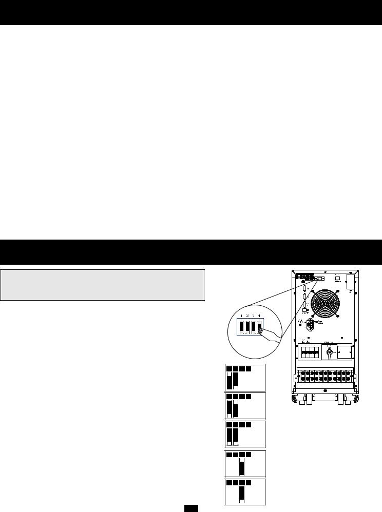
Modulo Eléctrico Panel Posterior (continuado)
10."Battery Start" Switch (Interruptor de Encendido de Baterías): Este interruptor de tecla basculante le permite encender su UPS en frío y usarlo como una fuente de energía independiente cuando no existe corriente C.A. El interruptor activa el inversor del UPS C.C./C.A. Antes del encendido en frío de su UPS, asegúrese que el módulo de corriente y los modulos de baterías externas estén instalados adecuadamente. Apriete y sostenga el interruptor "Battery Start" y después apriete el interruptor de ON/OFF para encender su UPS. Para apagar después del encendido en frío, apriete el interruptor ON/OFF.
11.AC Input Breaker (Interruptor de Entrada C.A.): Controla la entrada de corriente al UPS durante su operacion normal.
12.Bypass AC Input Breaker (Interruptor de Derivacion de Entrada C.A.): Controla la entrada de corriente al UPS durante la operacion de "BYPASS".
13.Remote "Emergency Power OFF" (EPO) Connector (Conector Remoto de Apagado de Emergencia OFF (EPO): Este jack modular permite el apagado de emergencia remoto. Véase "Comunicaciones" para más detalles.
14.Inverter Operación DIP Switches (Operación del Inversor Interruptores de luces bajas): Detrás del panel removible hay cuatro Interruptores DIP que deberan ser ajustados para que correspondan con el voltaje y frecuencia de entrada. Los parámetros de ajuste del interruptor DIP para el voltaje y frecuencia de entrada deberán corresponder a su entrada. SU UPS NO CONVERTIRA el voltaje o la frecuencia.
15.Grounding Terminal (Terminal a Tierra): Este terminal conecta a un conductor de tierra. ES PELIGROSO OPERAR SU UPS SIN CONECTARLO. El tamaño recomendado del conductor es 8 AWG basado en el estándar UL 1778. Siga todas las regulaciones locales necesarias para el cableado eléctrico.
16.Stabilizers( Estabilizadores): Estos apoyos se extienden para prevenir que su UPS ruede o se voltee.
17.Battery Module Input Connector (Conector de Entrada del Modulo de Batería): Utilice este conector para conectar en serie módulos adicionales de baterias al primero. Retire el panel de cubierta para acceder a él. Refiérase al manual de usuario para módulos de baterías para las instrucciones de conexión y precauciones.
18.Battery Module Output Cable (Cable de Salida del Modulo de Batería): Utilice este cable para conectar el módulo de batería al módulo de corriente (o a otro módulo de batería si está utilizando más de uno). El módulo de corriente no arrancará sin estar conectado a un módulo con carga de batería. Refiérase al manual del usuario del módulo de baterías para las instrucciones de conexión y advertencias de seguridad.
19.Tower Mounting (Montaje de la Torre): Para más estabilidad durante la instalacion de la torre, puede ordenar bases de apoyo (# de modelo: 2-9 USTAND) que se venden por separado.
Instalación
OPERACION DEL INVERSOR OPERACION DE LOS PARAMETROS DE AJUSTE DE LOS INTERRUPTORES DE LUCES BAJAS
Con la ayuda de una pequeña herramienta, ajuste los cuatro interruptores de luces bajas para la operación del inversor (ubicados en el panel posterior de su UPS) para que correspondan con su voltaje de entrada, frecuencia de entrada y modo de operación deseado.
Selección del Voltaje de Entrada
(Interruptores de luz baja, DIP Switches #1 y #2)
Estos interruptores de luz baja deberán ser ajustados para que correspondan con el voltaje de entrada. Su UPS NO CONVERTIRA el voltaje.
Voltaje de Entrada |
Posición del Interruptor DIP |
|
|
220V |
#1 ARRIBA Y #2 ABAJO |
|
|
230V |
#1 ABAJO Y #2 ARRIBA |
240V |
#1 ABAJO Y #2 ABAJO |
Selección de Frecuencia de Entrada
(Interruptor DIP #3)
Los parámetros de frecuencia de entrada deberán corresponder con la frecuencia de entrada. Su UPS NO CONVERTIRA la frecuencia.
Frecuencia de Entrada |
Posición del Interruptor DIP |
|
|
50 Hz |
#3 ARRIBA |
60 Hz |
#3 ABAJO |
|
|
1 |
2 |
3 |
4 |
|
|
|
220V |
1 |
2 |
3 |
4 |
230V
1 2 3 4
240V
1 2 3 4
50 Hz
1 2 3 4
60 Hz
REFER TO USER'S MANUAL FOR TORQUING SPECIFICATIONS, USE COPPER CONDUCTORS ONLY. UTILISER SEULEMENT LES CONDUCTEURS DE CUIVRE.
20
Instalación (continuado)
Selección de la modalidad operativa
(Interruptor DIP #4)
La modalidad operativa "On-Line" proporciona una operación en línea con cero tiempo de transferencia. La modalidad de "Economía" proporciona operación en línea interactiva para mayor eficiencia cuando la protección en línea es innecesaria, reduciendo así los costos de operación sin afectar la fiabilidad energética del UPS durante una falla eléctrica.
Modalidad Operativa |
Posición del Interruptor DIP |
|
|
En línea |
#4 ARRIBA |
|
|
Economía |
#4 ABAJO |
|
|
UBICACION DEL UPS
1 2 3 4
En línea
1 2 3 4

 Economía
Si necesita mover su UPS a cortas distancias utilice sus ruedas. Estabilice el UPS soltando los estabilizadores a cada lado de la unidad. NOTA: No apile el módulo de corriente del sistema UPS o los módulos de las baterías externas.
CONEXION DE ENTRADA Y SALIDA
SELECCION DE CABLEADO
Escoja el cableado apropiado (deberá tener una capacidad de temperatura de 70° C y tamaño 6 AWG) para conectar su UPS a la toma de corriente C.A. y su equipo a su UPS.
CONEXIONES DE CABLEADO
Conecte sus cables a los bloques de terminales ubicados en los paneles posteriores de su UPS (véase el diagrama debajo).
¡PRECAUCION!
El personal cualificado deberá seguir todos los procedimientos requeridos por N.E.C. y todas las regulaciones locales requeridas para la adecuada instalación de aparatos con cableado permanente conectados a una fuente de energía. Asegúrese que los cables están provistos de manguitos y asegurados por conectores con grapas. Ajuste las conexiones con un par de no menos de 35 pulgadas-libra.
Salida |
|
|
|
|
Entrada |
||||||
|
|
|
|
|
|
|
|
|
|
|
|
|
|
|
|
|
|
|
|
|
|
|
|
Entrada |
Fase |
Fase |
Fase |
"Bypass" |
Principal R |
Principal S |
Principal T |
NOTA: La salida "BYPASS" y los terminales de Fase Principal R tienen hecho un cortocircuito de fabrica.
PRECAUCION: Observe las regulaciones requeridas para la conexión de cables, [como por ejemplo el Código Nacional de Electricidad (NEC) en los Estados Unidos] en todo momento. El uso de cables de tamaño inadecuado puede dañar su equipo y causar riesgo de incendio. Una a tierra el UPS y el equipo que vaya a conectar como se muestra en el diagrama.
CONEXION A |
UPS |
TIERRA |
|
HACIA LA CONEXION
A TIERRA DEL
EDIFICIO
CARGA 1 |
CARGA 2 |
CARGA 3 |
21

Instalación (continuación)
CONEXION DEL MODULO DE BATERIA EXTERNA (requerido)
Conecte el modulo de batería al módulo de corriente. Consulte el manual del usuario que vino junto a su módulo de batería. Inserte de forma completa el conector al extremo del cable del módulo de batería en el conector que se encuentra en el panel posterior del módulo de corriente. Puede que salten chispas, esto es normal. NOTA: El modulo de corriente no tiene baterías internas y no funcionará hasta que el módulo de baterías esté conectado. Los módulos de baterías están cargados de manera completa durante su fabricación. Sin embargo, no espere una total capacidad de respaldo, especialmente si el módulo de batería ha permanecido almacenado durante mucho tiempo. Una vez que el sistema UPS sea conectado a la toma eléctrica principal, permita que el módulo de baterías se recargue durante 12 horas. Una vez que el sistema UPS esté en uso, cargará las baterías y mantendrá la carga de forma automática. Si lo necesita, podrá conectar mas módulos de batería en serie insertando cada cable en el conector del módulo previo.
REFER TO USER'S MANUAL FOR TORQUING SPECIFICATIONS, USE COPPER CONDUCTORS ONLY. UTILISER SEULEMENT LES CONDUCTEURS DE CUIVRE.
Módulo de Batería |
Modulo eléctrico |
Panel posterior |
Panel posterior |
VERIFICACION DE LA CONDICION DE LA BATERIA
Cuando el UPS opere a través de baterías, la alarma y el visualizador le alertarán sobre el nivel de carga de batería en su UPS.
Nivel de Carga de la Batería |
Alarma |
Visualizador LCD |
|
|
|
|
|
|
|
LLENA |
Beep Corto (cada 2 segundos) |
ON BATTERY |
(OPERANDO CON BATERIAS |
|
|
|
BATT = XXV XX% |
BATERIA = XXV XX%) |
|
|
|
|
|
|
BAJA |
Beep corto (cada ½ segundo) |
BATTERY LOW |
(BATERIA CON CARGA BAJA |
|
|
|
BATT = XXV XX% |
BATERIA = XXV XX%) |
|
|
|
|
|
|
POR DEBAJO |
Beep Continuo |
BATTERY UNDER |
(BATERIA DESCARGADA |
|
|
|
SHUT DOWN |
CIERRE) |
|
|
|
|
|
|
22

Operación (Condiciones Normales)
ENCENDIDO DEL UPS
•Asegúrese que el UPS este instalado adecuadamente (vea la sección de instalación) y que la llave manual del "bypass" (derivación) esté colocada en NORMAL.
•Encienda los interruptores de entrada (Input) C.A. y Bypass (derivación) C.A. ON.
•Si la entrada de C.A. le da corriente de forma normal dentro de los parámetros seleccionados (véase Selección del Voltaje de Entrada y Especificaciones) su carga conectada se energizará. Sin embargo, el inversor del UPS aún no esta encendido. Apriete el interruptor frontal "ON/OFF" para que el inversor comience a operar.
•Si la entrada de corriente C.A. no está proporcionando energía normalmente, usted tiene la opción comenzar la batería. (su batería deberá estar cargada por lo menos parcialmente para que esta operación tenga éxito.) Presione y aguante el interruptor de encendido de batería (Battery Start) y el interruptor "ON/OFF" por tres segundos para encender su UPS en la modalidad de BATERÍA ("ON BATTERY") Observe que algunos equipos electrónicos pueden utilizar más amperios durante el arranque; cuando encienda desde la batería, considere reducir la carga inicial del UPS.
•El UPS realizará una breve autoprueba y mostrará los resultados en el visualizador LCD. (Véase la sección de autoprueba, para la secuencia del visualizador.) Después de una autoprueba con éxito, el UPS proporcionará corriente ALTERNA desde el inversor a su carga.
APAGADO DEL UPS
•Apague el interruptor frontal ON/OFF (Colóquelo en OFF). Su carga todavía estará energizada. El inversor está ahora apagado, pero su UPS no se desactiva completamente. El visualizador LCD mostrará "BYPASS".
•Apague los interruptores de entrada C.A. y bypass de entrada C.A. (OFF) Su carga no estará energizada y el visualizador del LCD estará oscuro.
23
 Loading...