


ProgrammableMultibandAmplifier
TMB 10A, TMB 10B, TMB 10C, TMB 10S
|
|
|
|
|
Model |
Item no. |
|
|
TMB 10A, TMB 10B, TMB 10C, TMB 10S |
324575/76/77/78 |
|
|
|
|
triax.com |
|
Version |
EN |

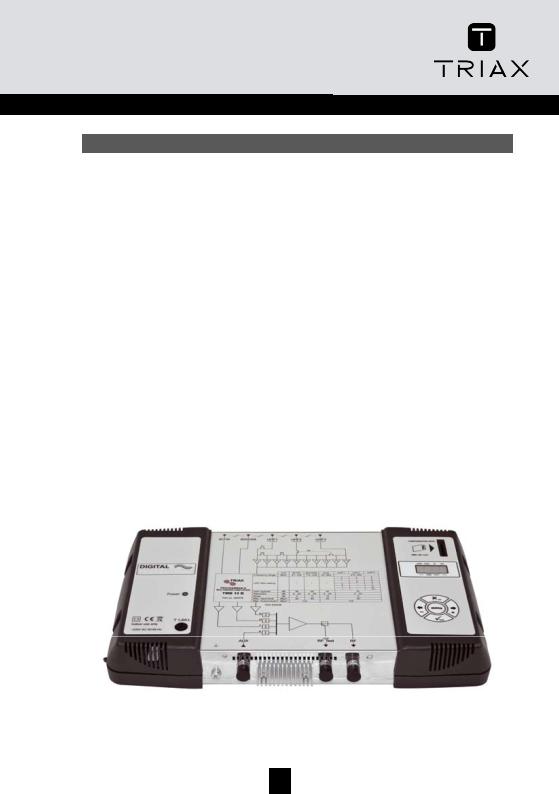
TMB Programmable Multiband Amplifier
TMB 10A • TMB 10B • TMB 10C • TMB 10S
GB
General information .............................................................................................................................. |
2 |
Safety Instructions ................................................................................................................................ |
3 |
Installing the unit................................................................................................................................... |
4 |
Connecting the unit ............................................................................................................................. |
4 |
Programming the unit ........................................................................................................................... |
5 |
Factory reset ....................................................................................................................................... |
5 |
Date of manufacture............................................................................................................................ |
5 |
Configuring the unit............................................................................................................................. |
6 |
Operrratttiiingprrriiinciiipllle.......................................................................................................................... |
6 |
Menus ..................................................................................................................................................... |
6 |
CHAN.......................................................................................................................................... |
6 |
LEVEL ........................................................................................................................................ |
6 |
CHANMenu.................................................................................................................................... |
7 |
DiiistttrrriiibutttiiionofffUHFfffiiilllttterrrs................................................................................................................ |
7 |
UHFfffiiilllttterrrwiiidttth(((CHANmenu)))........................................................................................................ |
9 |
Fiiinetttuniiing .................................................................................................................................... |
10 |
Confffiiigurrriiingtttheattttttenuatttorrrs(((LEVELmenu))).................................................................................. |
11 |
AutttomatttiiicUHFgaiiincontttrrrolllAutttomenu ....................................................................................... |
12 |
CARDMenu.................................................................................................................................. |
13 |
SATMenu ..................................................................................................................................... |
18 |
Diagrams .............................................................................................................................................. |
19 |
Technical Specifications..................................................................................................................... |
23 |
Notes..................................................................................................................................................... |
25 |
2
GB
General information
The processing units in the TMB10 range are used to selectively filter analogue and digital UHF channels. These units also couple and amplify VHF programmes according to the satellite band model (IF).
TMB10 units have one amplified wide band coupling input; 10 UHF filters, distributed over 3 inputs with programmable bandwidth from 1 to 7 channels (8 to 56 MHz), making it suitable for most situations.
An individual setting for each filter or frequency band, and automatic control of the UHF output level, for aligning service plan levels.
TMB-10A – Ref.: 324575 |
TMB-10B – Ref.: 324576 |
5 inputs: BI - FM, BIII - DAB, AUX, UHF1, UHF2 |
6 inputs: BI - FM, BIII - DAB, AUX, UHF1, UHF2, UHF3 |
UHF Gain = 55 dB |
UHF Gain = 55 dB |
BI - BIII Gain = 48 dB |
BI - BIII Gain = 48 dB |
AUX Gain = 39 dB |
AUX Gain = 39 dB |
UHF output level = 124 dBµV (DIN 45004B) |
UHF output level = 124 dBµV (DIN 45004B) |
|
|
TMB-10C – Ref.: 324578 |
TMB-10S – Ref.: 324577 |
6 inputs: BI - FM, BIII - DAB, AUX, UHF1, UHF2, UHF3 |
8 inputs: BI - FM, BIII - DAB, AUX, UHF1, UHF2, UHF3, 2 |
UHF Gain = 45 dB |
x SAT |
BI - BIII Gain = 45 dB |
SAT Gain = 40 dB |
AUX Gain = 40 dB |
UHF Gain = 48 dB |
UHF output level = 124 dBµV (DIN 45004B) |
BI - BIII Gain = 43 dB |
|
AUX Gain = 33 dB |
|
UHF output level = 120 dBµV (DIN 45004B) |
|
SAT output level = 120 dBµV (EN 50083-3) |
|
|
3

TMB Programmable Multiband Amplifier
TMB 10A • TMB 10B • TMB 10C • TMB 10S
GB
Safety Instructions
Important: The unit should only be opened by a qualified technician.
•Disconnect the unit before carrying out any work on it, as some powered components are dangerous (risk of electrical shock).
•To maintain the temperature of the unit within its normal operating range, ensure the free circulation of air around the unit (avoid placing it in enclosed spaces). The ventilation grids must be free of any obstruction.
•Ensure that no liquids can penetrate inside the unit (splashes and/or run off).
•Do not install the unit in a damp place. If there are traces of condensation on the unit, do not use it until it has dried completely.
•The mains power cable and the HF connection cables must be in good condition and free to move (neither crushed nor obstructed).
•The mains plug, easily accessible for the technician, must be out of reach of children.
Earthing the unit
•Your aerial installation must comply with the requirements specified by the European provisions EN 50083 (conformity of collective installations) and EN 60065 (standards in force for electrical protection).
Replacing fuses
•Only a qualified technician can replace defective fuses.
Electromagnetic compatibility (EMC)
•Ensure that the screws on the box are properly tightened.
•Cables and connection terminals should show no signs of rust.
4

GB
Installing the unit
We recommend you install the unit in a sufficiently ventilated place. Natural ventilation must be able to occur through the ventilation grids; leave a minimum space of 15 cm around the unit to ensure maximum ventilation.
When installing or cabling the unit, we recommend you disconnect the mains power cable.
Connecting the unit
Note: UHF inputs are remotely supplied and protected against short circuits. The power available is 12 or 24V, 50mA max. The preamplifier is detected automatically; only the remote power voltage can be programmed.
|
Unit |
BI-FM |
BIII-DAB |
AUX |
UHF1 |
UHF2 |
UHF3 |
SAT |
|
Frequency range |
MHz |
47÷108 |
174÷230 |
47÷862 |
|
|
470÷862 |
|
950÷2150 |
|
|
|
|
|
3 |
|
5 |
2 |
|
|
|
|
|
|
1 |
|
7 |
2 |
|
UHF lter setting |
|
/ |
/ |
/ |
– |
|
8 |
2 |
/ |
|
3 |
|
– |
7 |
|||||
|
|
|
|
|
|
|
|||
|
|
|
|
|
1 |
|
– |
9 |
|
|
|
|
|
|
– |
|
– |
10 |
|
Gain (typical) |
dB |
43 |
43 |
33 |
|
|
48 |
|
40 |
Attenuator |
dB |
0…20 |
0…20 |
0…20 |
|
|
0…20 |
|
0…20 |
Noise |
dB |
5 |
5 |
10 |
|
|
9 |
|
6 |
Max. Input level |
dBµV |
80 |
80 |
80 |
|
|
80 |
|
79 |
Max. Output level* |
dBµV |
|
116 |
|
|
120 |
|
|
|
*DIN 45004B |
|
|
|
|
|
|
|
|
|
5
TMB Programmable Multiband Amplifier
TMB 10A • TMB 10B • TMB 10C • TMB 10S
GB
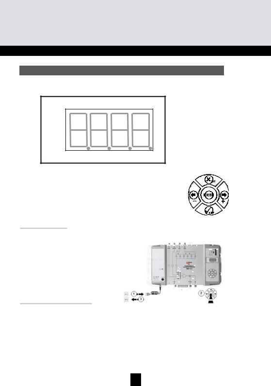
Programming the unit
A 4-digit display and a keypad are all you need to programme the unit. Follow the procedure below for configuring the various parameters.
CHAN LEVEL IN SAT
Digit 1 Digit 2 Digit 3 Digit 4
____ CARD AUTO ____
When the unit is powered on:
• |
the programme mode is in standby: |
|||
• |
by default, the system is configured as follows: |
|||
|
o |
UHF1 |
Î |
3 UHF filters |
|
o |
UHF2 |
Î |
0 UHF filters |
|
o |
UHF3 |
Î |
7 UHF filters |
• all the UHF filters are deactivated (display "- -"),
• the attenuators are at zero.
Factory reset
If necessary, to revert to factory settings, follow the procedure below:
1.Disconnect the power cable
2.Press the esc button and hold it
3.Connect the power cable
The unit erases all the programming parameters, including the PIN code, and switches to standby mode.
•You can release the esc button when the display shows “8888”
Date of manufacture
If necessary, to consult the unit’s date of manufacture and version, press the button - & +. For 2 seconds, the unit displays the date of manufacture in the format; A-SS with A being the last digit of the year of manufacture, SS the week of manufacture.
6

GB
Configuring the unit
On powering on, the unit is in standby mode, a light segments flashes across the display:
Operating principle
To access the configuration menus, press the menu button until the light segment is under the menu to open and press enter.
To summarize:
•To scroll through the menus, use the menu button.
•To enter a menu, press enter.
•To exit a menu, press the menu button.
Note:
If the button is not pressed for one minute, the unit switches to standby mode.
Menus
CHAN
Configuration of UHF filters:
•Channel
•Bandwidth (1 to 7 channels; 8 to 56 MHz)
LEVEL
Configuring of attenuators.
IN
Configuration of filter distribution on UHF1, 2 and 3 inputs.
Selection of remote power supply (12 or 24 VDC).
AUTO
Use of the AGC.
Automatic alignment of UHF programmes.
CARD
Reading and saving of configurations
Activation and configuration of the PIN code.
SAT
Configuring of IF attenuators. 9 dB equalization ON/OFF
Selection of remote power supply (0, 13 or 17 VDC). Selection 22 kHz (ON/OFF).
7

TMB Programmable Multiband Amplifier
TMB 10A • TMB 10B • TMB 10C • TMB 10S
GB
CHAN Menu
TMB units have 6 or 10 configurable UHF filters. The UHF filters are distributed over the three inputs UHF1, UHF2, UHF3 as shown below.
TMB 10A
Input |
UHF1 |
UHF2 |
UHF3 |
Number of filters per |
4 |
2 |
- |
3 |
3 |
- |
|
UHF input |
1 |
5 |
- |
|
- |
6 |
- |
TMB 10B, C & S
Input |
UHF1 |
UHF2 |
UHF3 |
|
3 |
5 |
2 |
Number of filters per |
1 |
7 |
2 |
- |
8 |
2 |
|
UHF input |
3 |
- |
7 |
|
1 |
- |
9 |
|
- |
- |
10 |
Each UHF filter can be configured for a bandwidth of 8 to 56 MHz (1 to 7 channels).
Distribution of UHF filters
Go to the menu IN by placing the light segment under the IN mark and press enter.
•Press enter again to change the configuration of the UHF inputs (part of the display flashes)
•Press the buttons + or - to select the distribution of the filters over the UHF inputs.
Notes:
Each UHF filter can be deactivated. Just configure the filter in question to the value – in the "CHAN" menu.
8
 Loading...