

Page 1
TRENDnet User’s Guide
Cover Page
Page 2

TRENDnet User’s Guide
Table of Contents
i
Contents
Product Overview ................................................................................. 1
Package Contents ............................................................................................................................................ 1
Features .......................................................................................................................................................... 1
Product Hardware Features ............................................................................................................................ 2
Wall Mount Installation ................................................................................................................................... 3
Installation, Using the AutoRun Wizard ................................................. 3
Option A, Connect camera to your network using a network cable ................................................................ 5
Option B, Connect Camera to your wireless network using WPS (Wi-Fi Protected Setup) button .................. 8
Option C, Connect Camera to your Wireless Network Manually ................................................................... 11
Starting the TRENDnet Cloud Service ................................................... 15
Cloud Mode 1: ............................................................................................................................................... 17
Cloud Mode 2: ............................................................................................................................................... 17
Cloud Mode 3: ............................................................................................................................................... 18
Cloud Service Interface and configuration .................................................................................................... 18
Admin ...................................................................................................................... 34
Time and Date ......................................................................................................... 36
Network ........................................................................................................................................................ 37
LAN Settings ............................................................................................................ 37
Wireless Setup ........................................................................................................ 39
Dynamic DNS ........................................................................................................... 40
Cloud Setting ........................................................................................................... 41
Cloud Status ............................................................................................................ 42
Audio/Video Setting ...................................................................................................................................... 42
Image Setup ............................................................................................................ 44
Action ............................................................................................................................................................ 45
Recording ................................................................................................................ 45
Video Clip ................................................................................................................ 49
Snapshot ................................................................................................................. 50
Preset Position ........................................................................................................ 52
Mobile Apps........................................................................................ 23
Patrol Position ......................................................................................................... 52
Find the IP address of your camera(s) .................................................. 25
Web Browser Management ................................................................. 25
Main Web User Interface .............................................................................................................................. 30
Camera Toolbar ............................................................................................................................................. 30
Setup ............................................................................................................................................................. 31
Wizard ........................................................................................................................................................... 31
Step 1: LAN Settings ................................................................................................ 31
Step 2: Internet Settings.......................................................................................... 32
Step 3: DDNS Settings ............................................................................................. 32
Step 4: Camera Name Settings ................................................................................ 33
SD Management...................................................................................................... 52
Motion Detection .......................................................................................................................................... 53
Sound Detection ............................................................................................................................................ 54
Tools .............................................................................................................................................................. 55
System ..................................................................................................................... 55
Firmware Upgrade .................................................................................................. 56
Advanced ...................................................................................................................................................... 56
TRENDnetVIEW Pro Software .............................................................. 58
Troubleshooting ................................................................................. 59
Step 5: Time Settings ............................................................................................... 33
Step 6: Setup Complete ........................................................................................... 34
System ........................................................................................................................................................... 34
© Copyright 2016 TRENDnet. All Rights Reserved.
Page 3

1
TRENDnet User’s Guide
TV-IP862IC
Product Overview
TV-IP862IC
Package Contents
In addition to your camera, the package includes:
Multi-Language Quick Installation Guide
CD-ROM (Utility & User’s Guide)
Network cable (1.8m / 6ft)
Power adapter (12V DC, 1A) (1.5m / 5ft)
If any package contents are missing or damaged, please contact the retail store, online
retailer, or reseller/distributor that the item was purchased from.
Features
TV-IP862IC
The TV-IP862IC records at 1280 x 720 pixels (720P HD), 30 FPS (frames per second). You
can manage up to 32 TRENDnet cameras with the included complimentary camera
management software. The TV-IP862IC also includes adjustable motion detection
recording areas, email alerts, scheduled recording sessions, Pan/Tilt auto-patrol, dateand-time overlays, two-way audio, an adjustable lens, and four times digital zoom. A
wall/ceiling mounting kit is included and the camera’s off white housing blends into
most environments.
Easy Installation
The TV-IP862IC includes a CD-ROM with a setup wizard that guides you through the
installation process.
Wide Platform Support
The TV-IP862IC supports TCP/IP networking, HTTP, and other Internet related protocols.
The TV-IP862IC can be integrated easily into other Internet/Intranet applications
because of its standards-based features.
10/100 Ethernet Support
The TV-IP862IC supports 10/100 Ethernet.
Web Configuration
Once setup is complete, administrators can use a standard web browser to access
images and video, configure the camera over an intranet or over the Internet.
Administration via web browser over the Internet means the IP camera can be accessed
and administered from anywhere in the world.
Broad Range of Applications
With today’s high-speed Internet connections, many scenarios for the application of
your network camera exist, including industrial and public monitoring of properties such
as homes, offices, banks, hospitals, child-care centers and amusement parks.
Pan & Tilt
The TV-IP862IC can pan side to side at a remarkable 330 degrees and tilt 115 degrees.
Recording Quality
The TV-IP862IC can record 1280x720 (720p HD) video resolution.
© Copyright 2016 TRENDnet. All Rights Reserved.
Page 4
2
TRENDnet User’s Guide
TV-IP862IC
IR LED
Line Out
Ethernet Port
Light Sensor
Microphone
Camera Lens
Power/Link LED
Antenna
WPS Button
Reset Button
Rear Air
Micro SD Slot
Focus Ring
WPS Indicator Light
Power Port
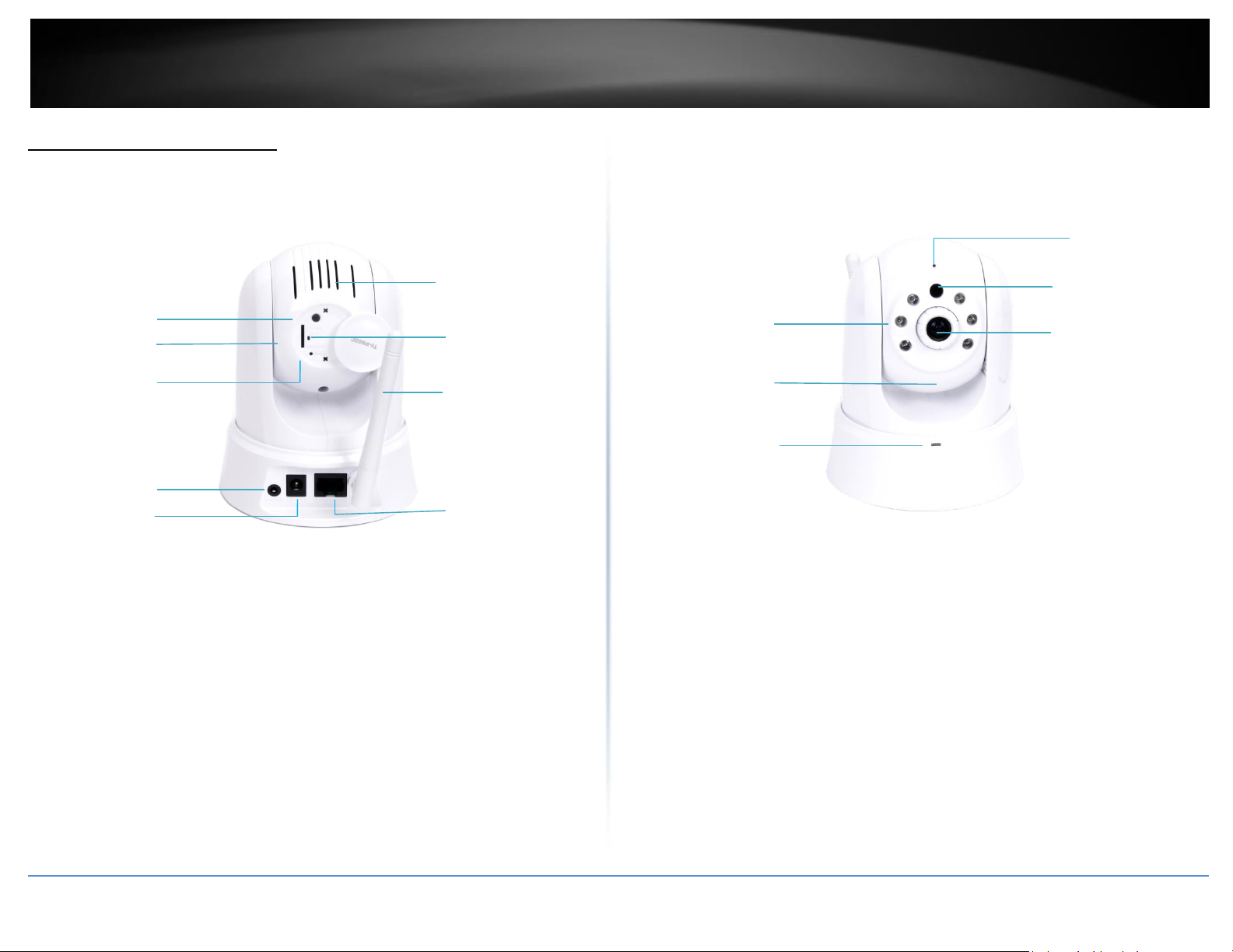
Product Hardware Features
Rear Panel View
Front Panel View
Ethernet Port – Connect Ethernet cables to your wired network devices.
Power Port – Connect the included power adapter from your camera to an
available power outlet.
Note: Use only the adapter that came with your camera.
Reset Button – Use an item such as a paperclip to push and hold this button for
5 seconds and release to reset your camera to its factory defaults.
WPS (Wi-Fi Protected Setup) – Push and hold this button for 5 seconds to
activate WPS. The button LED is blinking green when WPS is activated.
Antenna – 2dBi detachable antenna.
Line Out – Connects an external active speaker
Micro SD Slot – Insert a micro SD card into this slot to store video/image data.
Rear Air Vent – This is to cool theTV-IP862IC and dissipate heat.
IR LED – Built-in 6 IR LED, 850nm, for night vision uses. (for TV-IP862IC)
Light Sensor – Detects the light source to turn IR on or off.
Focus Ring – Turn to adjust the focus of the camera.
Microphone – Built-in microphone for audio can be turned on or off.
Power – This LED indicator is solid blue when your camera is powered on.
Otherwise, if this LED indicator is off, there is no power to your camera.
Link – This LED indicator is blinking green when there is connection/data to
your camera.
Camera Lens – Focal Length: 4.6 mm, F2.0; Focal Depth: 20 cm – infinity
© Copyright 2016 TRENDnet. All Rights Reserved.
Page 5
3
TRENDnet User’s Guide
TV-IP862IC
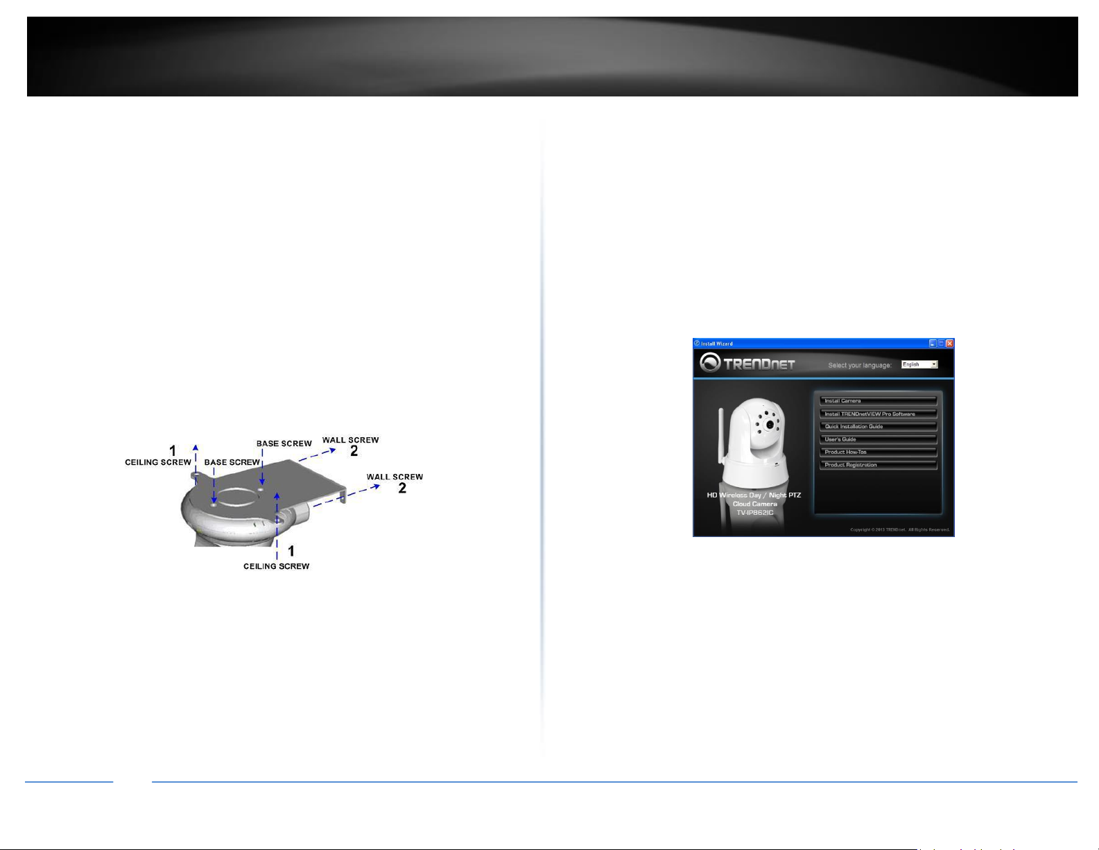
Wall Mount Installation
Please do not mount the camera until after you complete the installation steps from the
CD-ROM. Temporarily place the camera next to your computer.
To attach the metal plates, carry out the following:
Remove the two rubber pads under the base of the Camera.
Slide the metal plate onto the base of the camera, making sure that the two
holes on the base of the camera align with the two screw holes on the base of
the camera.
Secure the metal plate to the base of the Camera with the two screws
provided.
The camera can now be mounted to the ceiling or a wall. See the diagram
below for more information.
Installation, Using the AutoRun Wizard
Insert the included CD-ROM into your CD/DVD drive. The Install Wizard program will
run automatically.
Note: If the Install Wizard does not run, you may have autorun disabled on your
machine. In this case, browse to the CD drive and run InstallWizard.exe to begin the
installation wizard.
Begin by selecting a language from the drop-down list. There is a choice of five
languages – English, French, German, Spanish, and Russian.
Next, click Install Camera and follow the on-screen steps to continue the installation.
© Copyright 2016 TRENDnet. All Rights Reserved.
Page 6
4
TRENDnet User’s Guide
TV-IP862IC
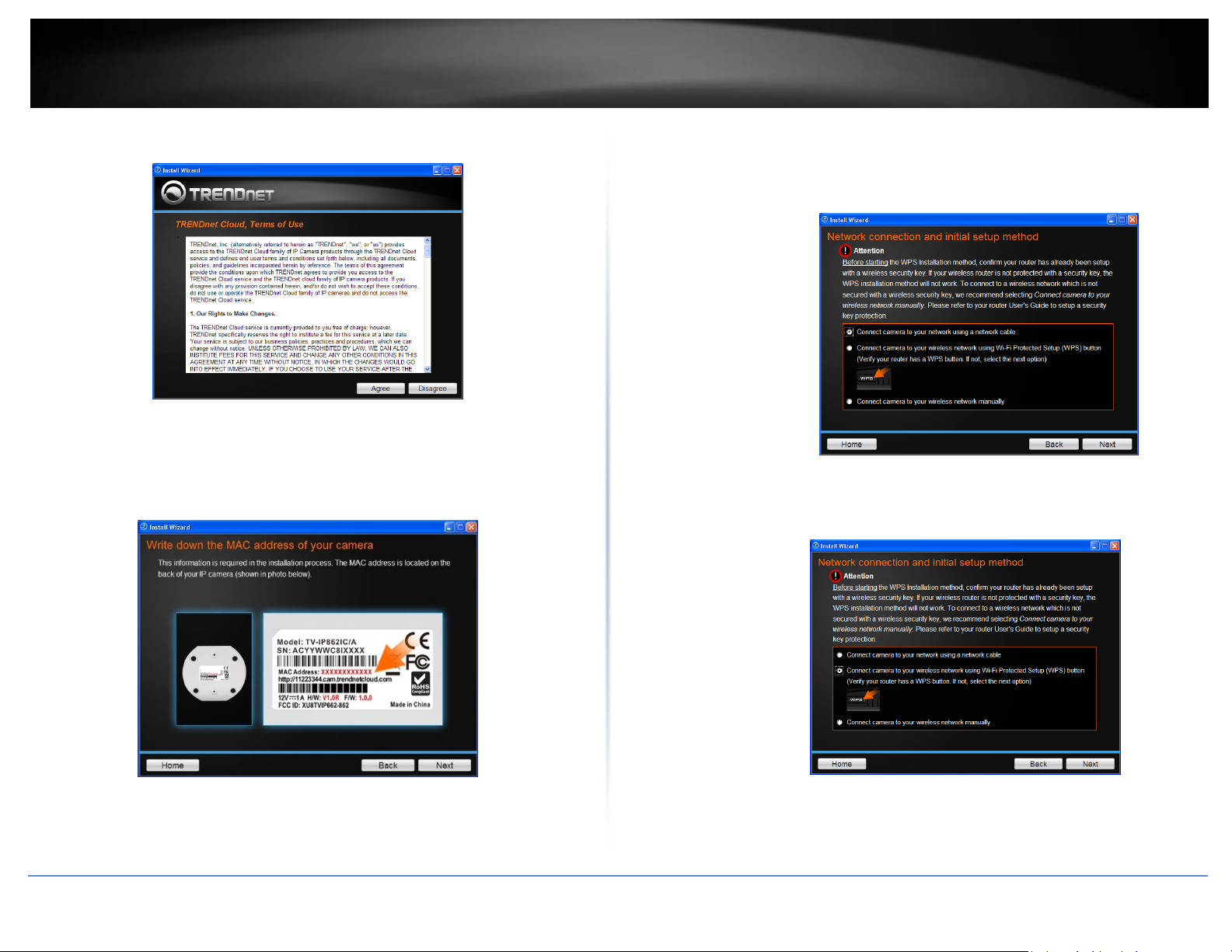
1. This is TRENDnet’s Terms of Use. Click Agree to continue.
2. The next step references information on the camera itself. Go to your camera
and check the details at the bottom of the device. Click Next to continue, Back
to go to the previous screen or Home to return to the Main Menu. Also
enclosed, is a sticker with the same details attached.
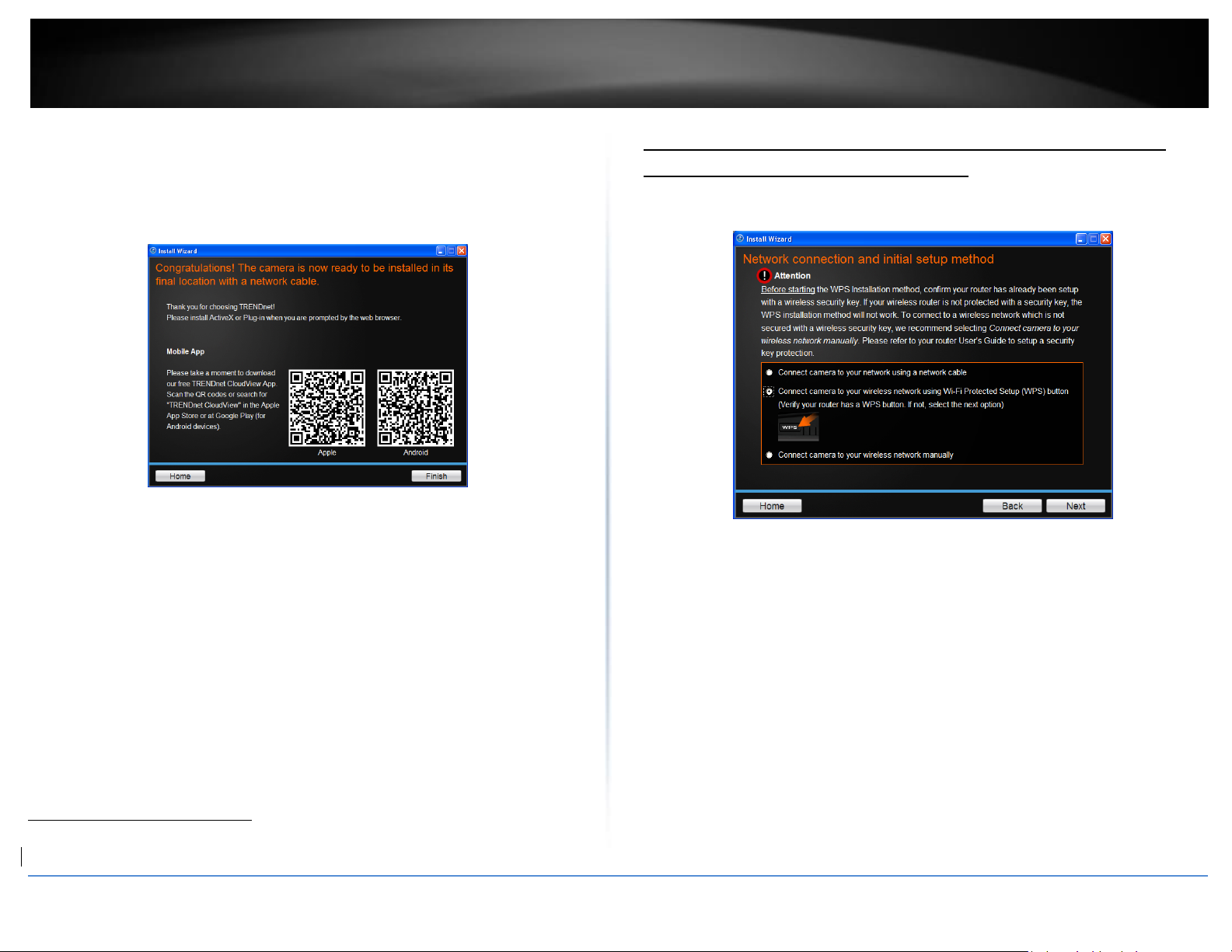
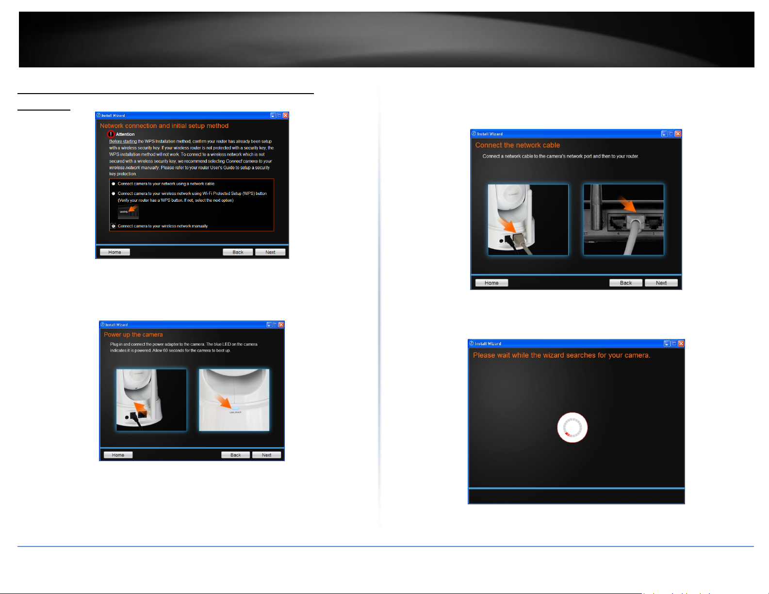
3. The most important part of the setup process is the network connection type.
There are three options:
a. Connect camera to your network using a network cable
b. Connect camera to your wireless network using Wi-Fi Protected Setup
(WPS) button (Verify your router has a WPS button. If not, select the
next option).
© Copyright 2016 TRENDnet. All Rights Reserved.
Page 7

5
TRENDnet User’s Guide
TV-IP862IC
c. Connect camera to your wireless network manually.
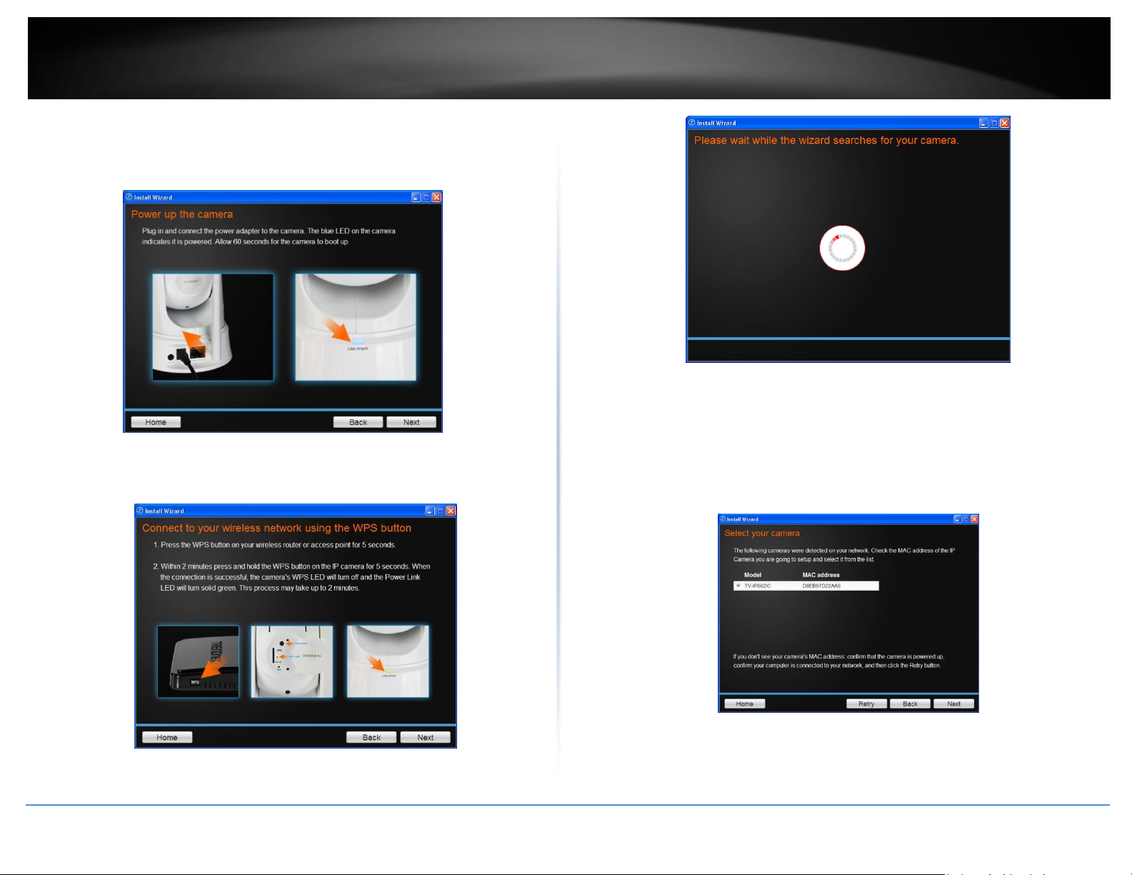
2. Follow the instructions in the next screen to Power up the Camera. Connect one end
of the power adapter to the camera and watch the LED flicker. Click Next to continue,
Back to go to the previous screen or Home to return to the Main Menu.
Option A, Connect camera to your network using a network cable
1. The basic connection type is “A” using a network cable. Let’s begin the installation
process using the network cable connection first. Click this radio button and click Next
to continue, Back to go to the previous screen or Home to return to the Main Menu.
© Copyright 2016 TRENDnet. All Rights Reserved.
3. Connect one end of the network cable to your camera and the other end to your
router. Click Next to continue, Back to go to the previous screen or Home to return to
the Main Menu.
Page 8
6
TRENDnet User’s Guide
TV-IP862IC
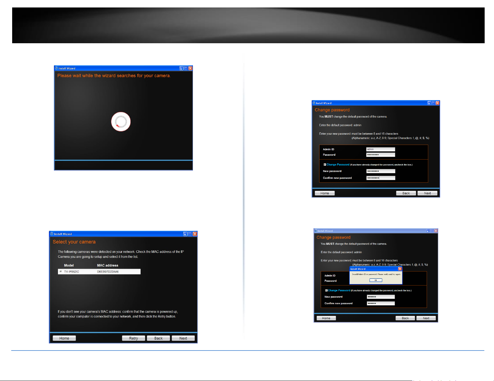
4. The wizard searches the network for your camera.
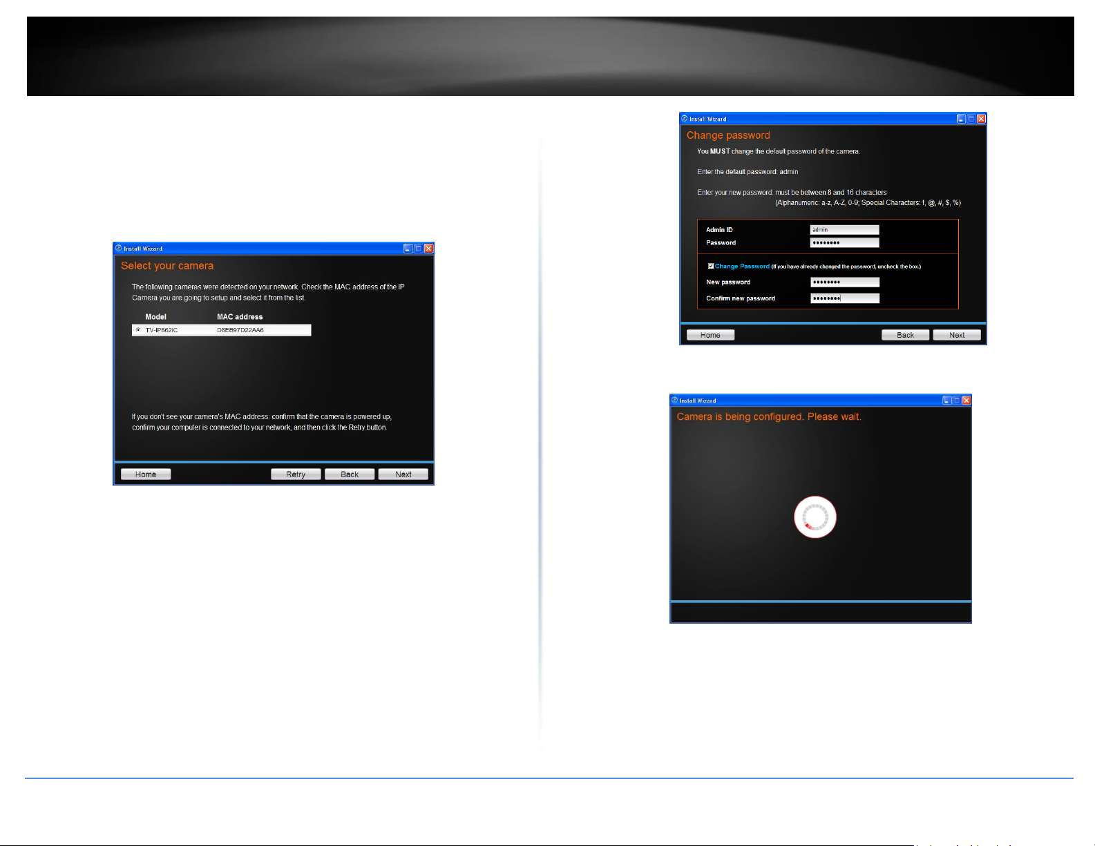
5. If you only have one camera on your network, the wizard will automatically
select it (as shown below). Otherwise, if you have more than one camera, it
provides several options from the list. The wizard provides the Model Name
and MAC Address of the camera. If you do not see any of your camera(s) in the
wizard, click Retry to scan for the camera again. Click Next to continue, Back to
go to the previous screen or Home to return to the Main Menu.
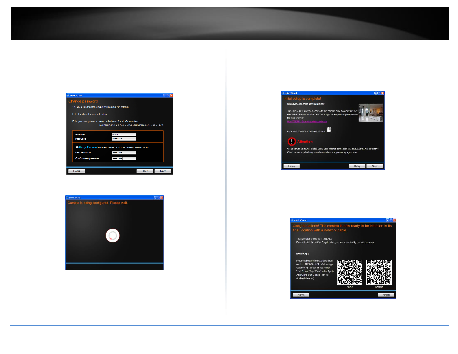
6. Password Settings. Follow the instructions on the screen. The default
username and password is admin. Tick the Change Password checkbox to enter
the new password details. The password should be between 8 and 16
characters. Click Next to continue, Back to go to the previous screen or Home
to return to the Main Menu.
If you have entered the incorrect admin details, you are prompted to change the
configuration, as shown below.
© Copyright 2016 TRENDnet. All Rights Reserved.
Page 9
7
TRENDnet User’s Guide
TV-IP862IC
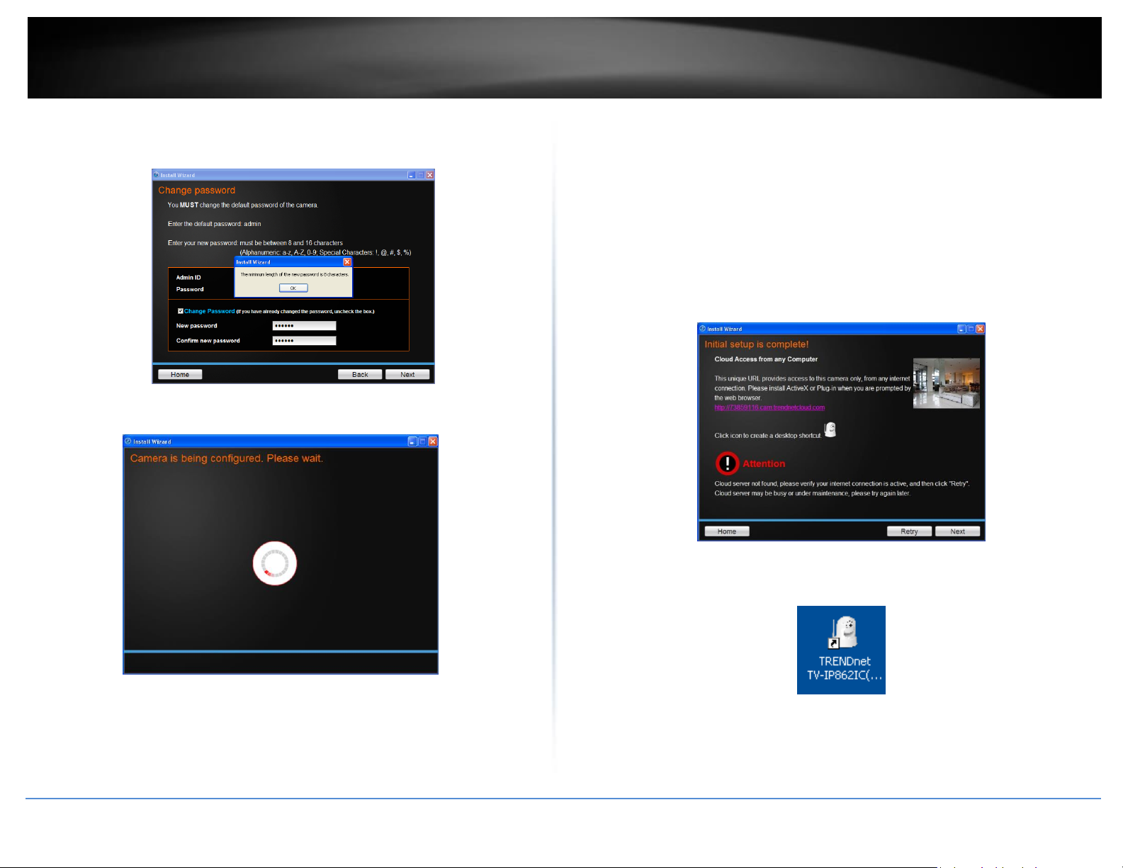
If the password length is less than 8 characters, you are also prompted to alter the
configuration, as shown below.
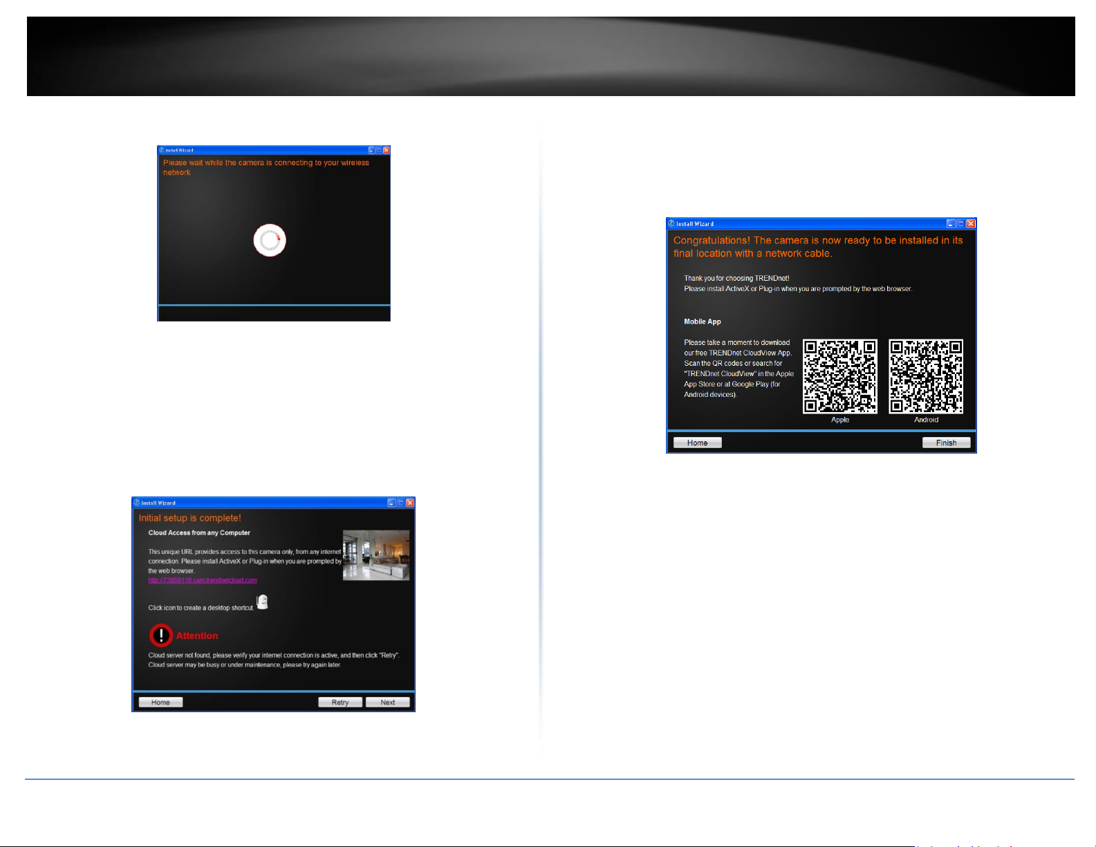
7. The wizard configures your parameters.
8. The initial setup is complete. The main feature is the Cloud Access accessibility
feature. Click the link(s) or icon below to create a shortcut on your desktop.
Also, below the icon is a warning. This warning is only shown when the Internet
connection is inactive or the Cloud server cannot be found. Make sure the
Internet connection is active, click Retry. If the Cloud server isn’t found, the
server may be busy or under maintenance. Under these circumstances, click
Retry later again. If there is no warning, click Next.
Please refer to Starting the TRENDnet Cloud Services section for additional
Cloud service information.
Click on the product image to create a shortcut on the desktop. A shortcut will
be created.
© Copyright 2016 TRENDnet. All Rights Reserved.
Click the link provided to browse the settings in the browser.
Page 10
8
TRENDnet User’s Guide
TV-IP862IC
1
2
9. Scan the barcode to download the TRENDnet CloudView App for Apple iOS or
Android™1 . The app can also be found by searching TRENDnet from the Apple
App Store or Google Play™2.
Please refer to Mobile Apps section for additional app features information.
You are now ready to use your camera. Click Finish to exit.
Option B, Connect Camera to your wireless network using WPS (Wi-Fi Protected Setup) button
Tick the WPS option
Please consider these points before using WPS.
Android is a trademark of Google Inc.
Google Play is a trademark of Google Inc.
© Copyright 2016 TRENDnet. All Rights Reserved.
Find the access point (AP) or wireless router you wish to connect to from the
Available AP drop down menu.
In most cases you should leave the Channel set to Auto as the AP will
determine the channel of operation.
Select the type of authentication and encryption required by the access point
and enter the Key required to connect.
Click Next to continue, Back to go to the previous screen or Home to return to the Main
Menu.
Please read the next steps carefully as it pertains to the WPS feature on your router and
camera.
Page 11
9
TRENDnet User’s Guide
TV-IP862IC
1. Follow the instructions on the screen to Power up the Camera. Click Next to
continue, Back to go to the previous screen or Home to return to the Main
Menu.
3. If you only have one camera on your network, the wizard will automatically
select it (as shown below). Otherwise, if you have more than one camera, it
Follow the instructions and click Next to continue. If you wish to go to the previous
screen, click Back or Home to return to the main menu.
provides several options from the list. The wizard provides the Model Name
and MAC Address of the camera. If you do not see any of your camera(s) in the
wizard, click Retry to scan for the camera again. Click Next to continue, Back to
go to the previous screen or Home to return to the Main Menu.
2. The wizard will now search for your camera.
© Copyright 2016 TRENDnet. All Rights Reserved.
Page 12
10
TRENDnet User’s Guide
TV-IP862IC
4. Password Settings. Follow the instructions on the screen. The default
username and password is admin. Click the Change Password checkbox to
enter the new password details. The password should be between 8 and 16
characters. Click Next to continue, Back to go to the previous screen or Home
to return to the Main Menu.
found, the server may be busy or under maintenance. Under these
circumstances, click Retry later again. If there is no warning, click Next.
Please refer to Starting the TRENDnet Cloud Services section for additional
Cloud service information.
5. The wizard will now configure your parameters.
6. The initial setup has been completed. The main feature is the Cloud Access
accessibility feature. Click the link(s) or icon below to create a shortcut on your
desktop. Also, below the icon is a warning. This warning is only shown when
the Internet connection is inactive or the Cloud server cannot be found. Make
sure the Internet connection is active, click Retry. If the Cloud server isn’t
© Copyright 2016 TRENDnet. All Rights Reserved.
7. Scan the barcode to download the TRENDnet CloudView App for Apple iOS or
Android™ . The app can also be found by searching TRENDnet from the Apple
App Store or Google Play™.
Please refer to Mobile Apps section for additional app features information.
You are now ready to use your camera. Click Finish to exit.
Page 13
11
TRENDnet User’s Guide
TV-IP862IC
Option C, Connect Camera to your Wireless Network Manually
1. Follow the instructions in the next screen to Power up the Camera. Click Next
to continue, Back to go to the previous screen or Home to return to the Main
Menu.
2. Connect one end of the network cable to your camera and the other end to
your router. Click Next to continue, Back to go to the previous screen or Home
to return to the Main Menu.
3. The wizard will now search the network for your camera.
© Copyright 2016 TRENDnet. All Rights Reserved.
Page 14
12
TRENDnet User’s Guide
TV-IP862IC
4. If you only have one camera on your network, the wizard will automatically
select it (as shown below). Otherwise, if you have more than one camera, it
provides several options from the list. The wizard provides the Model Name
and MAC Address of the camera. If you do not see any of your camera(s) in the
wizard, click Retry to scan for the camera again. Click Next to continue, Back to
go to the previous screen or Home to return to the Main Menu.
6. The wizard will now configure your parameters.
5. Password Settings. Follow the instructions on the screen. The default
username and password is admin. Click the Change Password checkbox to
enter the new password details. The password should be between 8 and 16
characters. Click Next to continue, Back to go to the previous screen or Home
to return to the Main Menu.
© Copyright 2016 TRENDnet. All Rights Reserved.
Page 15
13
TRENDnet User’s Guide
TV-IP862IC
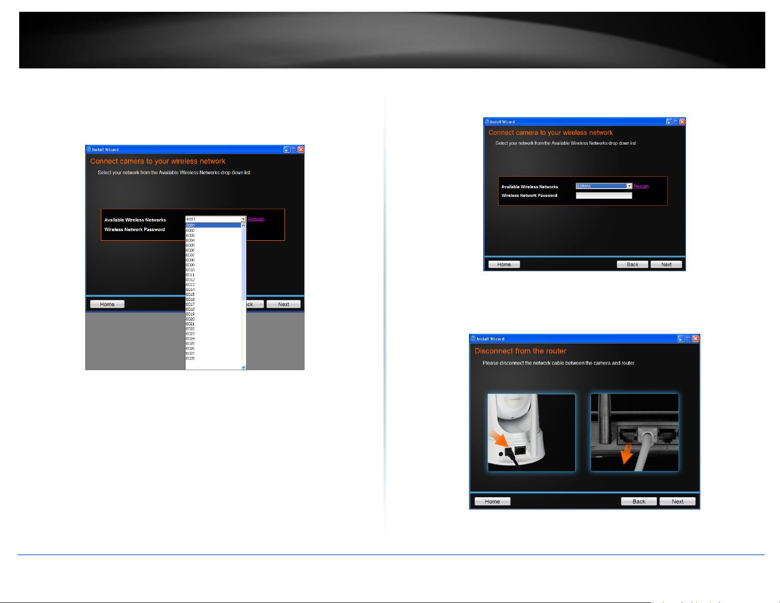
7. Once your wireless network has been discovered, the wizard will provide you
with an option to select the Available Wireless Network and also to provide a
Wireless Network Password. If you do not see your wireless network details,
click the Rescan link to scan the network again.
Once the wizard finds the wireless AP you are looking for, select it and enter the
wireless network password of the AP. Click Next to continue.
8. Next, you will be prompted to disconnect your network cable from the
camera/router. Click Next to continue, Back to go to the previous screen or
Home to return to the Main Menu.
The wizard will search for wireless Access Points. Click the Rescan button if you do not
find your AP.
© Copyright 2016 TRENDnet. All Rights Reserved.
Page 16
14
TRENDnet User’s Guide
TV-IP862IC
9. The camera will connect to the wireless network.
10. The initial setup has been completed. The main feature is the Cloud Access
accessibility feature. Click the link(s) or icon below to create a shortcut on your
desktop. Also, below the icon is a warning message. This warning message is
only shown when the internet connection is inactive or the cloud server cannot
be found. Make sure the internet connection is active, click Retry. If the Cloud
server isn’t found, the server may be busy or under maintenance. Under these
circumstances, click Retry again. If there is no warning, click Next.
Please refer to Starting the TRENDnet Cloud Services section for additional
Cloud service information.
11. Scan the barcode to download the TRENDnet CloudView App for Apple iOS or
Android™ . The app can also be found by searching TRENDnet from the Apple
App Store or Google Play™.
Please refer to Mobile Apps section for additional Cloud service information.
You are now ready to use your camera. Click Finish to exit.
© Copyright 2016 TRENDnet. All Rights Reserved.
Page 17
15
TRENDnet User’s Guide
TV-IP862IC
Starting the TRENDnet Cloud Service
When you first purchase the TV-IP862IC, it’s already configured to run on the internet
out of the box. To do this, you will need the following:
The TV-IP862IC must be connected to the network with internet
A DHCP router, with WPS enabled (optional), or the camera connected to a LAN
connection by a network cable.
Before starting the TRENDnet Cloud Service, please properly install the camera through
the installation steps on the Quick Installation Guide.
To access the cloud service, follow the steps below
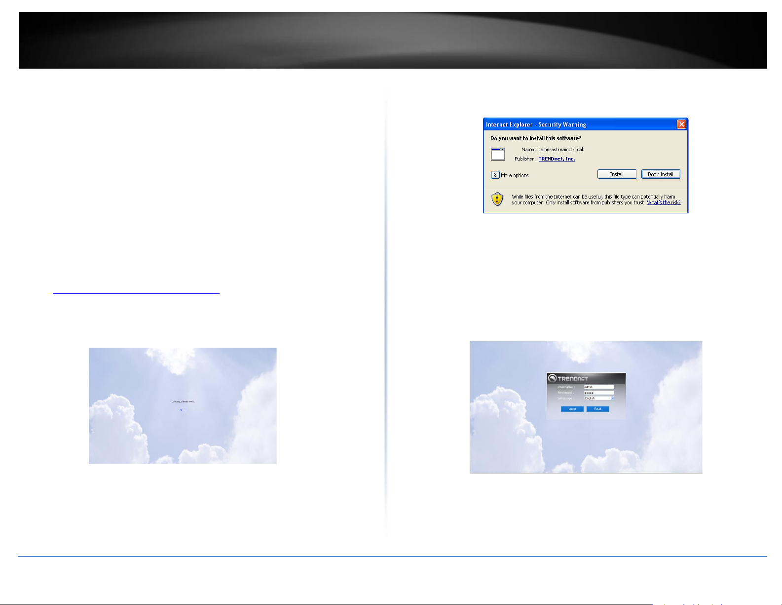
1. Open a web browser and type in the URL (eg:
http://73859116.cam.trendnetcloud.com) listed on the label located at bottom
of the camera. Write it down
2. You will reach the cloud service site
3. You will be prompted to install the plug-in needed for TRENDnet access. Click
Install.
4. The log-in screen will appear. Enter the default username (admin) and the
default password, admin, at the first time login without running installation
steps on CD-ROM ahead or soon after the camera reset. If you have done
installation via CD-ROM previously, please enter the password you have setup,
and click Login. If you don’t want to use the information that you just entered,
click Reset and reenter your data.
© Copyright 2016 TRENDnet. All Rights Reserved.
Page 18
16
TRENDnet User’s Guide
TV-IP862IC
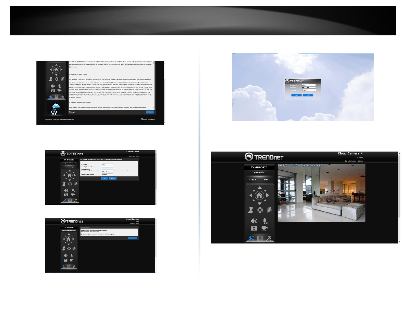
Note: For first time login, the site will prompt the Terms of Use and password change
windows as below. If you’ve configured the cameras previously, skip to Step 5.
5. Now, login with the new username and password and click Login.
The next is to change the username and password. Enter a username and the existing
password. Enter a new password and re-type it to confirm it. Click OK to complete.
The next screen will verify that your settings have been successfully changed. Click Login.
The camera will now display the Cloud view via the TRENDnet cloud service.
Depending on the network environment, you will be connecting to the cloud services
in one of the three modes. If you look under the Live View icon, you will notice Mode
1, 2, or 3. This indicates the connection mode currently in use.
© Copyright 2016 TRENDnet. All Rights Reserved.
Page 19
17
TRENDnet User’s Guide
TV-IP862IC
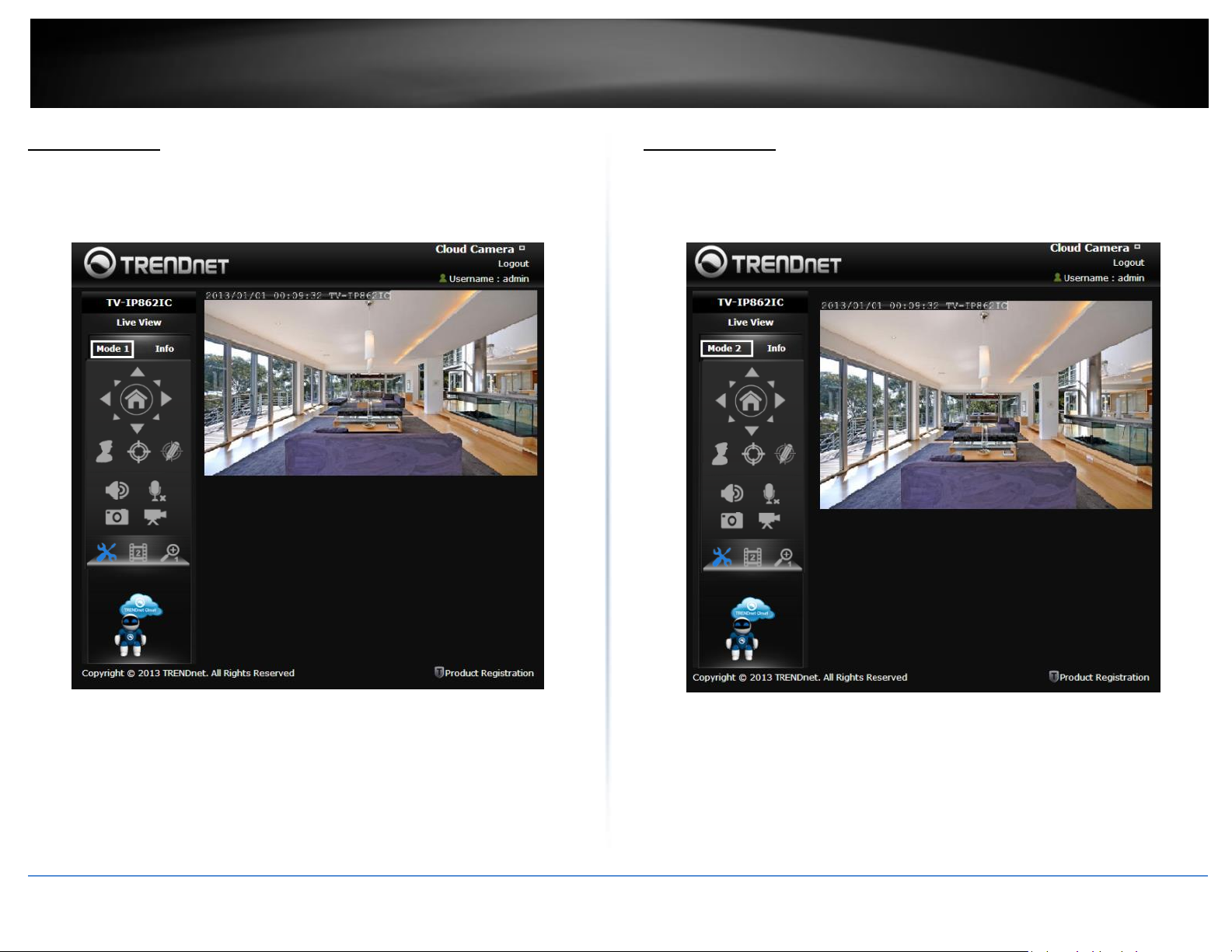
Cloud Mode 1:
Mode 1 indicates the camera is connecting directly to the Internet or local network. This
mode offers configuration and management options, together with an Advance
Configuration mode.
Cloud Mode 2:
Mode 2 indicates the camera is connecting to media in a peer-to-peer fashion to the
Internet or local network. This mode offers configuration and management options but
not an Advanced Configuration mode.
© Copyright 2016 TRENDnet. All Rights Reserved.
Page 20

18
TRENDnet User’s Guide
TV-IP862IC
Cloud Mode 3:
Mode 3 indicates the camera is connecting to the Internet or local network through a
firewall, or limited by your current network environment. This mode offers
configuration and management options but without Advanced configuration – just live
streaming for 5 minutes (the last 60 seconds is in countdown format). The firewall
settings limits live streaming for each user. The “red” notification at the bottom of the
viewing area warns users of the limited time. Refresh this screen continuously if you
wish to view your camera’s live stream.
Cloud Service Interface and configuration
After you login, you will see the main Cloud Service screen. Please properly install the
camera prior to cloud service login. The cloud service provides mostly use but not full
configuration settings. For full configuration settings, please refer to the Configuration
section.
What’s on the interface?
© Copyright 2016 TRENDnet. All Rights Reserved.
Page 21

19
TRENDnet User’s Guide
TV-IP862IC
1. The camera model name.
2. Live View mode.
3. Mode type
4. Notifications (Info on camera)
5. Pan/Tilt Control (Camera directional remote control)
6. Preset List (the list of your Preset Positions.)
7. Edit a Preset Name and Preset Position.
8. Speaker on your PC. Click this button to toggle between Sound and Mute.
9. Microphone on your PC. Toggle between On/Off.
10. Snapshot – take a snapshot
11. Start recording. Toggle between Start/Stop live view recording into your
TV-IP862IC folder, under the “My Document” folder, on your PC.
12. Configure settings in the cloud service.
13. Profiles (Select the camera profile).
14. Aspect Ratio (Zoom in and zoom out.)
15. Click to logout
16. Username
17. Camera Image
18. Fit to screen
19. Product Registration
20. Patrol once continuously at selected pre-set positions (Please refer to the
“Patrol Position”, under the “Configuration”, for details.)
© Copyright 2016 TRENDnet. All Rights Reserved.
Under Configure settings in the cloud service, there are various options you can
reference to configure. Go through the different options to toggle cloud settings.
For Video Configuration
1. Profile: Select a Profile from the drop-down list.
2. Encoding Type: Select your video encoding type from the drop-down list.
3. Resolution: Select the video resolution size from the drop-down menu.
4. Frame Rate: Select the frame rate speed from the drop-down menu.
5. Encoding Method: Select an encoding method from the drop-down menu.
6. Bit Rate: Select the camera bitrate from the drop-down menu.
Click OK to put the changes into effect.
Page 22

20
TRENDnet User’s Guide
TV-IP862IC
For Audio Configuration
1. Click to enable the speaker.
2. Adjust the volume.
3. Click to enable the microphone.
4. Adjust the microphone volume.
Click OK to complete these settings.
For Image Configuration
1. Brightness: Use the slider to adjust the brightness.
2. Contrast: Use the slider to adjust the contrast.
3. Saturation: Use the slider to adjust the saturation.
4. Hue: Use the slider to adjust the hue.
5. Mirror: Click the checkbox to mirror the image.
6. Flip: Click the checkbox to flip the image.
7. Black and White: Click the checkbox to change the image to black and white.
Click OK to complete these settings.
© Copyright 2016 TRENDnet. All Rights Reserved.
Page 23

21
TRENDnet User’s Guide
TV-IP862IC
For System Configuration
1. Username: Only change the Admin username here.
2. Existing Password: Enter the existing Admin Password.
3. New Password: Enter the new password.
4. Confirm the Password: Enter the new password again.
Click OK to complete the settings.
For User Configuration
1. Manual Recording and Snapshot/Set Folder Storage – Click the button to Select
the directory you want to save your recordings and images. Once you have
highlighted the folder you wish to use, click OK.
Locate the folder/directory where you want to store your data, select it and click OK.
© Copyright 2016 TRENDnet. All Rights Reserved.
Page 24

22
TRENDnet User’s Guide
TV-IP862IC
For Advanced Configuration (Please Note: Only Admin user can operate this option in
Mode 1)
1. Advanced Camera Settings: Click the Settings button to be redirected your IP
camera. This configuration method is similar to the one you already have
locally if you use your local IP address.
During this process you are redirected to your external IP address which is the camera’s
webpage.
Profiles: - Camera View: The current cloud-based system allows you to set 4 Profiles for
each camera you setup. Select which video settings you want to view and create a
profile.
Zoom in and zoom out: Click this icon to zoom in and zoom out. Each camera selection
appears as you select a viewing option or view the aspect ratio using this icon.
Logout: Use this link to logout
Username: View the current user connected to the cloud.
: This is a Fit-to-Screen icon.
This is a Fit-to-Normal icon
Click this area to resize the screen back to normal view.
© Copyright 2016 TRENDnet. All Rights Reserved.
Page 25

23
TRENDnet User’s Guide
TV-IP862IC
3
Camera: This is the camera view
Mobile Apps
Using your mobile3 device, in this example it is an Android phone, touch the Bar Code
scanning app on your mobile device. Hold your mobile device up to the QR Code on the
wizard that reads “Android” and scan the image. The Bar Code app will read the QR
Code and record it.
The app will copy the QR link and provide a HTML link to the TRENDnet app. Click on the
link.
© Copyright 2016 TRENDnet. All Rights Reserved.
Please refer to the TRENDnet CloudVIEW Quick Installation Guide for features
supported in the CloudView application.
Page 26

24
TRENDnet User’s Guide
TV-IP862IC
You will be directed to the Google Play™ to download the app.
Download the app, install it and use the app on your mobile device to view the
TRENDnet camera.
Apple iOS version
Scan the QR Code using one of IOS’s QR Code apps. The app will automatically create an
HTML link to the iTunes App Store. Click the link.
You will be immediately directed to the iTunes App Store. Click the link to download.
© Copyright 2016 TRENDnet. All Rights Reserved.
Page 27

25
TRENDnet User’s Guide
TV-IP862IC
Find the IP address of your camera(s)
Please install the Setup Wizard utility software (for Windows only) from the setup
wizard folder on the CD by double clicking the setup file, to locate the IP address of your
camera(s) on the same network with your PC.
Web Browser Management
After completing the Autorun Wizard from the CD, you are ready to use your camera.
The camera’s built-in Web configuration utility is designed to allow you to easily access
and configure your TV-IP862IC camera. Open a web browser such as Internet Explorer®
and enter the IP address of your camera (through the setup wizard utility software on
the CD). To log in, type the Username admin and the password you created in the
Autorun Wizard. If you did not create a password or you just press the reset button for
reset, the default password is admin. After entering your password, click OK.
These initial steps are shown using Internet Explorer.
When you log in for the first time or camera reset, the TRENDnet Cloud Terms of Use
will appear. Click the Accept check box and click Next.
© Copyright 2016 TRENDnet. All Rights Reserved.
Page 28

26
TRENDnet User’s Guide
TV-IP862IC
The camera will save the information you have entered and restart in 10 seconds.
The Change Your Account page will appear. Under Admin User Name, leave it as
“admin” or change it accordingly. Enter the Old Password, enter the New Password, and
then re-enter the New Password to confirm it. Click OK to continue. Click Cancel if you
wish to discontinue.
The Congratulations page will appear. Click Login to go to the Login page again. To log
in, enter the Username admin and the newly created password. This page only appears
the first time log in.
© Copyright 2016 TRENDnet. All Rights Reserved.
Page 29

27
TRENDnet User’s Guide
TV-IP862IC
The home page for the TV-IP862IC will appear. Now enter the new username and
password you just created and click Log In.
PLEASE NOTE: Depending on the browser you are using, download the plugin needed
to view and access the camera feed.
After you have logged in, you will need to install the plug-in required. Click the link
below the camera view finder to install the plug-in.
The plug-in will be saved to your Downloads Folder. Click it to begin the installation.
Click Run to start the process.
Click Next to continue.
© Copyright 2016 TRENDnet. All Rights Reserved.
Page 30

28
TRENDnet User’s Guide
TV-IP862IC
The Camera stream control application will be installed.
Make sure all browsers are closed.
Click the “Close All” button to close all browser windows. Click the “Retry” button to
attempt it again or click the Cancel button to exit the plug-in installer.
Refresh your browser. The live camera image will be displayed.
This is the Microsoft Internet Explorer plug-in installation. Login to the camera again
after refresh the browser.
© Copyright 2016 TRENDnet. All Rights Reserved.
Page 31

29
TRENDnet User’s Guide
TV-IP862IC
At the top of the browser there will be a pop-up which will prompt you to add the
TRENDnet add-on.
Click the ActiveX pop-up to install it.
Another pop-up will appear to warn you that you’re installing an add-on. Accept the
add-on and click the Install button.
Once the add-on is installed, Internet Explorer will now display the streaming image.
The image below is displayed in both Internet Explorer and Chrome.
© Copyright 2016 TRENDnet. All Rights Reserved.
Page 32

30
TRENDnet User’s Guide
TV-IP862IC
COMPONENT
DESCRIPTION
Passive Profile
This profile, in grey, means the camera is
deselected.
Active Profile
This profile, in yellow, means the camera
is selected.
Full Screen Mode
The viewable screen is expanded to full
screen mode.
Snapshot
Click this button to take a snapshot of
image in the viewfinder.
Storage Folder
Select this icon to select the folder where
you want to store video feeds.
Audio
Click this button to toggle between sound
and mute.
Microphone
Click this button to use the microphone on
the camera and listen to incoming audio.
IR LED
Click this button to toggle the on/off IR
LED Day/Night mode.
Zoom In/Zoom Out
There are different zoom options under
Main Web User Interface
1. Live View – view the live image.
2. Setup – Configure the camera settings.
3. Registration – Register your device with TRENDnet.
4. Record button – Click this button to enable recording.
5. Sound/Motion Trigger – Click this button to activate sound and motion.
6. Directional Controller – Control the direction of the camera.
7. Pan Button – Click this button to pan the camera.
8. Patrol Button – Click this button for the camera to patrol once continuously at
the selected pre-set positions.
9. Stop – Click this button to stop al Pan/ Tilt/Patrol.
10. Go To – Select a preset position from the drop-down menu.
11. Pan Speed – Select a Pan speed from the drop-down menu.
12. Tilt Speed – Select a Tilt speed from the drop-down menu.
13. Language – Select a language from the drop-down menu.
14. Displays the timestamp.
15. Displays the live image.
16. Product name and Model number.
Camera Toolbar
© Copyright 2016 TRENDnet. All Rights Reserved.
Page 33

31
TRENDnet User’s Guide
TV-IP862IC
Zoom In/Zoom Out. The viewing angle can
be zoomed in from 1 times, 2 times, and 4
times.
Mode Level
There are four modes available: Mode 1,
2, 3, 4.
Wizard
The first screen in the Setup panel displays a Welcome to Internet Connection Setup
Wizard. Click Next to continue.
Setup
View camera settings:
1. Login to the camera
2. Click Setup. The main configurable screen appears.
From the menu on the left side of the screen, select an option.
Step 1: LAN Settings
Under LAN Settings you are provided with two choices, IPv4 Settings and IPv6 Settings.
Select DHCP for the router to choose your IP address. Click Next.
© Copyright 2016 TRENDnet. All Rights Reserved.
Page 34

32
TRENDnet User’s Guide
TV-IP862IC
For Static options, click Static IP Address.
In the Static IP address field, type in the IPv4 IP Address, the Subnet Mask, Default
Gateway, Primary DNS and/or Secondary DNS servers. There is also an option to include
a Search Domain if you have one.
When you configure static IP settings, click the radio button next to IPv6 Static IP
Address. The field now extends to further options. Type in the IPv6 IP Address in the
field provided. Then enter the Default Gateway details, a Primary DNS, and a secondary
DNS.
Step 2: Internet Settings
If your ISP requires a username and password, now is the time to complete the empty
fields. Click the Enable checkbox. Enter a Username and Password, and click the Next
button.
Step 3: DDNS Settings
Under DDNS Settings, click the checkbox to enable this feature. In Server Address, select
one of the domains from the drop-down menu. The field to the left of the drop-down
menu will automatically populate. Under Host Name enter the name the DDNS service
provided. Enter a Username and Password, repeat the password and finally enter the
Timeout. Timeout states the time DDNS is updated. Click Next to continue.
Click the Next button to continue.
© Copyright 2016 TRENDnet. All Rights Reserved.
Page 35

33
TRENDnet User’s Guide
TV-IP862IC
Step 5: Time Settings
From the drop-down menu, select a Time Zone. Click the checkbox to enable daylight
saving. To edit further options, either select Auto Daylight Saving or Set DST manually.
Auto Daylight will set the Daylight Savings time for you automatically. If you select DST
manually, you can offset the time within 1-2 hours. Then select a start time and an end
time from the drop-down menus provided. You can also click the “Keep current date
and time” which maintains the current time and date of the camera. Other options
include, “Synchronize with Network Time Protocol server”. Ask your administrator if you
have a server like this. The last option, “Setup a Date and Time manually”, allows you to
manually configure the date and time from the drop-down menus provided.
Alternatively, you can also click “Sync with Computer Time”. This uses the current time
settings on the computer you are using to sync with the camera’s time. Click Next to
continue.
Step 4: Camera Name Settings
Enter a name for the camera. This feature is helpful when you have more than one
camera setup. When complete, click Next.
© Copyright 2016 TRENDnet. All Rights Reserved.
Page 36

34
TRENDnet User’s Guide
TV-IP862IC
Step 6: Setup Complete
This is the final screen of the wizard. It shows the configuration options you selected.
Click Apply to make the changes. After you click through, a notice will appear to mention
that the camera will restart in 60 seconds and that it’s saving the settings. After the
camera restarts, you will be directed back to the start of the wizard.
© Copyright 2016 TRENDnet. All Rights Reserved.
System
Admin
Password Settings
In this section there are two configuration parts – Admin and Time and Date. These
settings can be configured using the Setup Wizard but if you have already done the
wizard and want to return to these settings, this is the place to do it.
1. Enter the Old Password (30 characters is the maximum length)
2. Enter the New Password (30 characters is the maximum length)
3. Confirm New Password – Repeat the password you have just entered.
4. Click Save.
Please Note the password can only contain: Alphanumeric: A-Z, a-z, 0-9, and Special
Characters: !, @, #, $, %
Add User Account
1. User Name – enter a new username in this field.
2. New Password – enter a password for the user in this field.
3. Confirm New Password – Repeat the password you have just entered.
4. Click Add to continue.
User List
The User List is now populated with the name(s) of the user(s) you have added to the
above configuration. If you wish to delete a user, select the user from the drop-down list
and click Delete.
Authentication
1. RTSP Authentication – click the checkbox if you wish to enable the authentication of
Real-time Transport Streaming Protocol
2. HTTP Authentication – click the checkbox if you wish to enable HTTP authentication.
3. Snapshot URL Authentication – click the checkbox if you wish to enable snapshot
authentication of the current video stream using the hyperlink next to it.
4. Click Save to continue.
Page 37

35
TRENDnet User’s Guide
TV-IP862IC
Device Settings
1. Camera Name – In this field enter a name for the camera.
2. OSD – Click the OSD checkbox if you wish to have an On-screen display.
3. Label – If you have clicked the OSD previously, enter a name under the Label field
to make the name visible. Also, click the Time Stamp checkbox if you wish to add a
timestamp to the image. Click Save to continue.
4. LED Light – From the drop-down list, you have the option to select Power/Link, Off,
or Blinking. These options allow you to adjust the LED settings according to your
requirements.
5. Calibrate the Device – Click the Calibrate the Device button to do exactly what it
says. The camera will now pan and tilt to get the system into calibration mode.
© Copyright 2016 TRENDnet. All Rights Reserved.
Page 38

36
TRENDnet User’s Guide
TV-IP862IC
Time and Date
Under Time Zone, select your region from the drop-down list
If you need to setup Daylight Saving time, click the Enable Daylight Saving
checkbox.
The two options available are Auto Daylight Saving and Set DST Manually. Click
Auto Daylight Saving to allow the camera to automatically adjust Daylight
savings time.
Select Set DST Manually if you wish to set the Daylight Savings time yourself. A
configurable drop-down menu appears allowing you to set the Daylight time
according to your requirements. Select an Offset time and from the drop-down
list (Month, Week, Day, Hour, and Minute) select a Start Time and an End
Time.
© Copyright 2016 TRENDnet. All Rights Reserved.
Automatic Time Configuration
Click the Synchronize with NTP Server checkbox to enable this feature. An NTP Server
field will open to prompt you to enter the server details.
Enter the server details, otherwise, consult your administrator for server details
Page 39

37
TRENDnet User’s Guide
TV-IP862IC
Set Date and Time Manually
Click the Setup Date and Time Manually checkbox to enable this feature. Here you will
have the option to select a Year, Month, Day, Hour, Minute, and Second or just click
Copy Your Computer’s Time button. Click Apply to continue.
Network
In this section there are five configuration parts – Network, Wireless Setup, Dynamic
DNS, Cloud Setting, and Cloud Status. These settings can be configured using the Setup
Wizard but if you have already done the wizard and want to return to these settings,
this is the place to do it
LAN Settings
There are wired LAN settings and wireless settings. For LAN settings follow these
instructions:
1. Select the radio button next to DHCP Connection under LAN Settings
2. Set the HTTP Port or leave the default at 80.
3. Set the RTSP Port or leave the default at 554.
4. Under UPnP, check the UPnP checkbox if you wish to use UPnP and the same
goes for UPnP Port Forward.
5. If you use Bonjour for Mac’s, click the Bonjour checkbox under Apple.
© Copyright 2016 TRENDnet. All Rights Reserved.
Page 40

38
TRENDnet User’s Guide
TV-IP862IC
For Static IP Address issues follow these steps (Best suited for experienced users):
1. Select the radio button next to Static IP Address under LAN Settings
2. Enter the IPv4 IP address in the field provided.
3. Set the Subnet Mask.
4. Set the Default Gateway IP settings from your router
5. Lastly, set the optional Primary and Secondary DNS fields.
6. Click Apply to complete the configuration.
If you are connecting the camera directly to a PPPoE network, the camera also has
configuration options for that.
1. Click the PPPoE checkbox. The viewable window will scroll down to reveal more
options.
2. Enter the User Name and Password/Confirm Password details. The Status should
indicate a Success or Failure (if you have a failure please consult your network
administrator or your internet provider)
3. Set the Port Settings, HTTP Port and RTSP Port.
4. Set the UPnP settings, UPnP and UPnP Port Forward.
5. Lastly, set the Apple, Bonjour settings.
6. Click Apply to complete the configuration.
© Copyright 2016 TRENDnet. All Rights Reserved.
Page 41

39
TRENDnet User’s Guide
TV-IP862IC
Wireless Setup
Click the Enable Wireless button to start using this wireless function. This function takes
a while to restart the camera
After the camera has restarted, the wireless configuration options become available.
1. Check the Wireless checkbox. The camera will automatically begin scanning
your wireless area.
2. Enter a name in the Network Name field manually, or select a wireless network
router from the drop-down list under Site Survey.
3. Under Wireless Mode select between Infrastructure and Ad-hoc mode.
Infrastructure Mode - An 802.11 networking framework in which devices communicate
with each other by first going through an Access Point (AP). In infrastructure mode,
wireless devices can communicate with each other or can communicate with a wired
network.
Ad-Hoc - An 802.11 networking framework in which devices or stations communicate
directly with each other, without the use of an access point (AP).
Under Security Mode, select among None, WEP, WPA-PSK, or WPA2-PSK.
None – means no security
WEP - a security protocol for wireless local area networks (WLANs) defined in the
802.11b standard. WEP is designed to provide the same level of security as that of a
wired LAN. LANs are inherently more secure than WLANs because LANs are somewhat
protected by the physicalities of their structure, having some or all part of the network
inside a building that can be protected from unauthorized access. WLANs, which are
over radio waves, do not have the same physical structure and therefore are more
vulnerable to tampering. WEP aims to provide security by encrypting data over radio
waves so that it is protected as it is transmitted from one end point to another.
WPA-PSK - uses a pass-phrase, which is between 8 and 63 characters long. This pass-
phrase is created and entered by the user into any client station’s configuration utility,
as well as into the AP. (A recommendation: do not pick a password already in use within
the network, and do not use a variation of your office address.) Generally, when
creating or setting up a wireless LAN, the first thing to be configured is the AP, which is
then followed by the configuration of client stations. Configuring an AP depends largely
upon the manufacturer’s instructions; client station configuration is where the real
choices about security come into play.
WPA2-PSK - it is a method of securing your network using WPA2 with the use of the
optional Pre-Shared Key (PSK) authentication, which was designed for home users
without an enterprise authentication server. To encrypt a network with WPA2-PSK you
provide your router not with an encryption key, but rather with a plain-English
passphrase between 8 and 63 characters long.
Depending on what Security Mode you are using, enter the Key in the key field next to
Key. Click the Show Hidden Key if you wish to see what you are typing.
© Copyright 2016 TRENDnet. All Rights Reserved.
Page 42

40
TRENDnet User’s Guide
TV-IP862IC
Click Apply to continue
© Copyright 2016 TRENDnet. All Rights Reserved.
Dynamic DNS
Dynamic DNS is a method of keeping a domain name linked to a changing IP address as
not all computers use static IP addresses. Typically, when a user connects to the
Internet, the user’s ISP assigns an unused IP address from a pool of IP addresses, and
this address is used only for the duration of that specific connection. This method of
dynamically assigning addresses extends the usable pool of available IP addresses. A
dynamic DNS service provider uses a special program that runs on the user’s computer,
contacting the DNS service each time the IP address provided by the ISP changes and
subsequently updating the DNS database to reflect the change in IP address.
1. Click the DDNS checkbox to enable DDNS settings.
2. Select the DDNS Server from the drop-down list.
3. Enter the Host Name you setup on this online server.
4. Enter a User Name in the field provided.
5. Enter a Password and confirm the Password.
6. Enter a Timeout, in hours, for the length you want the connection to stay
active.
7. Click Apply. The Status should change if you have configured the online DNS
settings correctly.
Page 43

41
TRENDnet User’s Guide
TV-IP862IC
Cloud Setting
This section covers connecting to the cloud. What is a cloud? Cloud computing is being
able to connect to your TV-IP862IC from any location. You can access and control the
device via the internet. To do this, click the radio button next to the Enable button. Click
Apply. Your selection is saved but there will not be any notification.
© Copyright 2016 TRENDnet. All Rights Reserved.
Page 44

42
TRENDnet User’s Guide
TV-IP862IC
Cloud Status
This section shows you the hyperlink to your cloud connection. Once you click the link,
your browser opens to the cloud interface. Click Refresh to update the image.
Audio/Video Setting
In this section there are two configuration parts – Audio and Video and Image Setup.
These settings can be configured using the Setup Wizard but if you have already done
the wizard and want to return to these settings, this is the place to do it.
Audio and Video – Video Profile
Encode Method: Is your Constant Bit Rate.
bps: Is the transmission speed of your data (4Mbps-64Kbps).
RTSP URL: is the RTSP URL where video streaming is accessed.
Each Profile offers different specifications. Select the specifications that best suite you.
Audio and Video - Video Profile 1:
Encode Type – H.264 & MPEG4
Resolution – 1280x720/640X352/320X176/160X80
FPS – 30/15/10/6/5/3/2/1
Encode Method – Two options available: CBR/Quality. CBR and Quality can be defined
as such. When users choose the CBR encode method, the camera selects the bitrate as
the first priority. The TV-IP862IC will adjust the image quality to fit the bitrate. When the
user chooses the Quality encode method, the camera select the bitrate to fit the quality
bps:
4Mbps/3Mbps/2Mbps/1.5Mbps/1Mbps/768Kbps/512Kbps/384Kbps/256Kbps/128Kbps
/64Kbps
Quality – Low/Fair/Standard/Good/Excellent
RTSP URL – play1.sdp
Under each profile settings there are six main functions, Encoder Type, Resolution,
Frames per Second, Encode Method, bps, and RTSP URL settings.
Encode Type: This sets the file format and file quality.
Resolution: This is the size of your image.
Frames Per Second: This is the speed at which each frame is captured.
© Copyright 2016 TRENDnet. All Rights Reserved.
Audio and Video – Video Profile 2
Encode Type – H.264 & MPEG4
Resolution –640X352/320X176/160X80
FPS – 30/15/10/6/5/3/2/1
Encode Method – CBR/Quality
Page 45

43
TRENDnet User’s Guide
TV-IP862IC
bps –
4Mbps/3Mbps/2Mbps/1.5Mbps/1Mbps/768Kbps/512Kbps/384Kbps/256Kbps/128Kbps
/64Kbps
Quality – Low/Fair/Standard/Good/Excellent
RTSP URL – play2.sdp
Encode Method – CBR/Quality
Bps –
4Mbps/3Mbps/2Mbps/1.5Mbps/1Mbps/768Kbps/512Kbps/384Kbps/256Kbps/128Kbps
/64Kbps
Quality – Low/Fair/Standard/Good/Excellent
RTSP URL – 3gpp
Audio and Video – Video Profile 3
Encode Type – JPEG
Resolution –1280x720/640X352/320X176/160X80
FPS – 30/15/10/6/5/3/2/1
Encode Method –Quality
Quality – Low/Fair/Standard/Good/Excellent
RTSP URL – play3.sdp
Video Profile Four for Mobile Devices Only - Options:
Encode Type – H.264 & MPEG4
Resolution – 1280x720/640X352/320X176/160X80
FPS – 30/15/10/6/5/3/2/1
© Copyright 2016 TRENDnet. All Rights Reserved.
Day/Night Mode
The TV-IP862IC allows users to record data in day and night mode. The TV-IP862IC has
LED’s for night mode. This section provides day and night options. You can select it to
run automatically, manually, in constant day mode or constant night mode.
Toggle this switch On/Off
Day/Night Settings
When you select "Day" mode, the viewing image is in normal "color" mode. However,
when you use "Night" mode, the viewing image turns black and white. The reason for
this is to create a clearer and smoother image. When you select "Auto" mode, the
Day/Night function is concealed.
Please Note: This allows you to set the camera to switch automatically from day to night
mode (default) or to permanently set the color and Black/White operations. Also note,
Page 46

44
TRENDnet User’s Guide
TV-IP862IC
even when the camera is set to color mode, it will switch to Black/White night vision if
there is no longer enough ambient light to support the color saturation.
Auto Mode - The camera automatically removes the filter by gauging the amount of
ambient light entering the lens.
Day Mode - In Day Mode, the camera switches on the IR cut filter to block infrared light
from reaching the sensor so colors aren't distorted.
Night Mode - In Night Mode, the camera switches off the IR cut filter so the sensor can
accept infrared light, helping to improve low light sensitivity.
Audio Setup
The TV-IP862IC allows users to record and broadcast audio. Click the Speaker checkbox
to change the volume settings on the camera’s speaker. Click the Microphone checkbox
and select your preference from the volume drop-down list. Click Apply to continue.
Image Setup
Just like any camera, you are able to make changes to the image settings. With the TVIP862IC, you can change the Brightness, Contrast, color scheme to Black/White, Flip the
image, change the Frequency, Shutter Speed, Saturation, Hue, Mirror, Auto Exposure
and White Balancing. The settings can be viewed “live” through the LIVE VIDEO display
in the forefront image
If you wish to discard the changes you made click the Reset to Default button.
© Copyright 2016 TRENDnet. All Rights Reserved.
Page 47

45
TRENDnet User’s Guide
TV-IP862IC
Action
Recording
In this section there are five configuration parts – Recording, Video Clip, Snapshot,
Preset Position, and SD Management.
This option allows you to record constantly. If you select Always bear in mind that the
Recording Type should be Video and that the source usually comes from Profiles 1, 2 or
4 under Source. Make sure the Micro SD Card settings are setup to accommodate the
huge storage space required for Always connections. Click Apply to complete the
configuration.
Trigger By – Schedule
This option allows you to record according to the schedule you setup. If you select
Schedule a calendar of the days of the week appear. Here you can select from each
day’s checkbox which days you want to setup and you can create a start and end time.
Click Apply to complete the configuration.
© Copyright 2016 TRENDnet. All Rights Reserved.
Page 48

46
TRENDnet User’s Guide
TV-IP862IC
Trigger By – Motion
This option allows you to record according to the motion parameters you setup. If you
select Motion, click the Schedule during checkbox. Then a calendar of the days of the
week will appear. Here you can click one of the day’s checkboxes and you can create a
start and end time. The Recording Type changes to pre-event or pre-event settings. This
means the camera will start recording before the motion event is observed and after the
motion event is inactive. These times can only be set in seconds. Click Apply to complete
the configuration.
Trigger By: Sound
This option allows you to record according to the audio parameters you setup. If you
select Sound, click the Schedule checkbox. You can now configure this by clicking the
checkbox of the days of the week. You can edit the Start and End times. Under
Recording Type, edit the Pre-event recording and Post-event recording times. Decide
whether you want to take a Snapshot or Video. Select the source, File Format, and
Recording Time duration (in minutes).
© Copyright 2016 TRENDnet. All Rights Reserved.
Recording Type
The two main sections here are Snapshot and Video. Snapshot takes a picture from your
recorded data and only works with Profile 3. Video captures source data from Profiles 1,
2, and 4 which is configurable in Video/Audio settings. Recording data can be recorded
in increments of 1-6 minutes.
Page 49

47
TRENDnet User’s Guide
TV-IP862IC
Target – Micro SD Card
Keep Free Space is used to set the capacity of your Micro SD card, preventing the
system from becoming unstable.
Recycle Click here to recycle the material on your Micro SD card. When the Micro SD
card is full all previous data is removed or recorded over thereby freeing up space.
These settings depend on the size of your SD card. The larger your SD card the more
storage space you have to record data. Recording data can be recorded in increments of
1-6 minutes. Cyclic settings can also be checked.
Target - Samba Network Device
The Samba Network Device requires a NAS server or a Linux server to operate. Under
Server, enter the server address. Click the Anonymous radio button to allow
anonymous users to send files to the Samba server. Then enter the Share Folder, Sub
Folder (if needed) and enter the Disk Space needed. Lastly, click the Recycle checkbox if
you want to recycle data in the Share Folder. This is useful when you don’t need to keep
all the recorded material.
If you click the Account radio button, then enter a Username and Password. This will
authenticate the user every time they log on to the samba server. Then enter the Share
Folder, Sub Folder (if needed) and enter the Keep Disk Space needed. Lastly, click the
Recycle checkbox if you want to recycle data in the Share Folder. This is useful when you
don’t need to keep all the recorded material. Remember to click the Apply button
whenever you want to save your changes.
Anonymous View
Account View
© Copyright 2016 TRENDnet. All Rights Reserved.
Page 50

48
TRENDnet User’s Guide
TV-IP862IC
Function
Recording
Video Clip
Snapshot
Note
Trigger
Type
Always Y Y
Y
Motion Y Y
Y
Motion
with
Schedule
Y Y Y
Schedule Y Y
Y
Sound Y Y
Y
Sound
with
Schedule
Y Y Y
Video profile
Options
Profile
1/2/4
supported
Profile
1/2/4
supported
Profile 3
supported
* For recording and
video clip, the
available video profile
options are 1/2/4.
* For snapshot, the
default video profile
option is profile 3.
Target
E-Mail N Y
Y
FTP N Y
Y
SD
Y N N
card
Samba Y N
N
Recording
Type
PreEvent
Y Y Y
* It's only supported
when trigger by
Motion/Sound is
activated.
* Snapshot, it’s
activated using 6
snapshots only.
Post Event
Y N Y
* It's only supported
when trigger by
Motion/Sound is
activated.
* Snapshot, it's
activated using 6
snapshots only.
Real
Time
Y
Y
Y
Recording features:
© Copyright 2016 TRENDnet. All Rights Reserved.
Page 51

49
TRENDnet User’s Guide
TV-IP862IC
Video Clip
Click the Video Clip checkbox to activate video recording events. There are three main
sections:
Trigger By: Always, Motion, Schedule, and Sound
Video Clip Type: Configure the recording options
Target: The targets available are FTP and E-mail. If you want to record data to an FTP
server, click FTP. If you want to record data to an E-mail account click E-mail.
The Trigger by and Video Clip settings are similar to the options under Recording Type.
Please see the above description for details.
Video Clip - Target
Target offers two variables, FTP or Email. You cannot select both. If you select FTP enter
the details as laid out in the FTP field.
FTP Server – this is your FTP server address
Port – this is the default FTP Port (21) address
Username – the username your FTP administrator provided
Password – the password your FTP administrator assigned you
Path – the directory
Filename Prefix – the filename you are using to access the data or save the data to
Interval – The interval range is set between 60 and 86400. The default interval is 300
seconds. The interval determines the time between two video clips, and is only used
when you trigger, Always and Schedule.
Send next FTP after – The range is 0 to 86400. The default setting is 10 seconds. This
determines the interval to send the next video clip once the previous video clip has
finished uploading from the FTP server. This is only available when trigger by Motion
and Sound is applied.
© Copyright 2016 TRENDnet. All Rights Reserved.
Passive Mode – It’s used as Server/client initiation access to bypass any proxies.
Click the Test button if you wish to verify your FTP server information. Click Apply to
confirm the configuration settings.
For Email
Recipient E-mail Address – the email address you want to send information to
SMTP Mail Server – the mail server domain details
Port - the default Port number (465)
Username – the username settings provided by your email administrator
Password - the password settings provided by your email administrator
Sender Email Address – the email address of the sender
Interval – The interval range is 60 to 86400. The default interval is 600 seconds. This
determines the time between two video clips, and is only used when you trigger by
Always and Schedule.
Send next email after – This determines the interval to send the next video clip after the
previous video clip is completed via E-mail. This is only available when you trigger by
Motion and Sound.
Page 52

50
TRENDnet User’s Guide
TV-IP862IC
Send next email after – the alert email interval times
Use SSL-TLS – this is a secure method (please consult your administrator before using
this setting). There are three options available: None, SSL-TLS or STARTTLS.
Click the Test button to proceed with a test. This will authenticate the email details with
your email server.
If the authentication is positive the test will be complete. If the test is a failure, the
result will not be successful. Click Apply to confirm the configuration settings.
Snapshot
These settings control SNAPSHOT settings for your camera. The Trigger by settings are
similar to settings above, so please view the settings above. The Snapshot Type provides
for a Single snapshot or 6 snapshots at 1-2 second intervals. The Target FTP and Email
settings are similar to settings explained above. Please read the configuration in the
above explanation. Click Apply to confirm the configuration settings.
Snapshot - Target
Target offers two variables, FTP or Email. You cannot select both. If you select FTP enter
© Copyright 2016 TRENDnet. All Rights Reserved.
the details as laid out in the FTP field. Click Apply to confirm the configuration settings.
FTP Server – this is your FTP server address
Port – this is the default FTP Port (21) address
Username – the username your FTP administrator provided
Password – the password your FTP administrator assigned you
Path – the directory
Filename Prefix – the filename you are using to access the data or save the data to
Page 53

51
TRENDnet User’s Guide
TV-IP862IC
Interval – The interval range is set between 60 and 86400. The default interval is 300
seconds. The interval determines the time between two video clips, and is only used
when you trigger, Always and Schedule.
Send next FTP after – The range is 0 to 86400. The default setting is 10 seconds. This
determines the interval to send the next video clip once the previous video clip has
finished uploading from the FTP server. This is only available when trigger by Motion
and Sound is applied.
Passive Mode – It’s used as Server/client initiation access to bypass any proxies.
Click the Test button if you wish to verify your FTP server information. Click Apply to
confirm the configuration settings.
Password - the password settings provided by your email administrator.
Sender Email Address – the email address of the sender.
Interval – The interval range is 60 to 86400. The default interval is 600 seconds. This
determines the time between two video clips, and is only used when you trigger by
Always and Schedule.
Send next email after – This determines the interval to send the next video clip after the
previous video clip is completed via E-mail. This is only available when you trigger by
Motion and Sound.
Send next email after – the alert email interval times
Use SSL-TLS – this is a secure method (please consult your administrator before using
this setting). There are three options available, None, SSL-TLS or STARTTLS.
Click the Test button to proceed with a test. This will authenticate the email details with
your email server.
If the authentication is positive the test will be complete. If the test is a failure, the
result will not be successful. Click Apply to confirm the configuration settings.
For Email
Recipient E-mail Address – the email address you want to send information to
SMTP Mail Server – the mail server domain details
Port - the default Port number (465)
Username – the username settings provided by your email administrator.
© Copyright 2016 TRENDnet. All Rights Reserved.
Page 54

52
TRENDnet User’s Guide
TV-IP862IC
Preset Position
This screen shows the software Pan/Tilt functions. You can set preset positions for fast
authentication. Most of the screen is taken up by the camera image. On the right of the
main screen is the Pan/Tilt dial.
Preset Position
1. Preset Name – Enter a name in the field provided to give the position a name.
2. Click Add.
3. To set a new Preset Position – Use the Pan & Tilt dial to select your Pan & Tilt speeds
and select the position.
4. Use the Set As Home button to choose it as your home screen.
5. Click the Default Home button if you wish to use this configuration as your default
home viewing area.
6. Preset Locations –Is a list of presets you can setup under Preset Position. This list is
populated with different camera views and angles.
Preset Locations
The Preset Locations is a list of presets you have setup under Preset Position. This list is
populated with different camera views and angles.
Patrol Position
This area is where you setup the movement of the Pan/Tilt during a particular time
frame. This Patrol Position can be setup with different Pan/Patrol Speeds and Dwelling
time(s) in seconds. The Dwelling Time is the duration the camera takes to span a
particular area.
1. Setup the Preset Position – Once you have setup the Preset in the previous
configuration list, select it from the Preset Locations.
2. Click the Select button to transfer this preset to the Patrol Position.
3. Set the position of your Preset. This depends on the priority of Patrol Position –
which item you want to make your priority.
4. For each Patrol Position you can adjust the Dwelling Time (in seconds). This indicates
the time needed to span each Preset while Patrolling.
5. Click Save to continue and finish the process.
SD Management
SD Card
The TV-IP862IC has a tiny Micro SD card slots at the back of the camera. Micro SD cards
are smaller than normal SD cards and require an adapter to work properly in a Micro SD
slot. Here you can format the SD card, select how many files you want to display on a
page, delete a page and also delete a file. When inserting a Micro SD card for the first
time, make sure you don’t have any important data stored on the card because once
you format the drive that data is lost.
1. Format the SD Card
2. Select how many files you want to display per page.
3. Setup recording by going to Action, Recording.
4. Designate space for the recording and click Apply.
5. To delete a file. Select the file from the list, click the Delete checkbox and click
Apply.
© Copyright 2016 TRENDnet. All Rights Reserved.
Page 55

53
TRENDnet User’s Guide
TV-IP862IC
Motion Detection
In this section there are five configuration parts – Video Motion, Sensitivity, and
Drawing Mode. Each of these components derives its feature set from a live video
stream.
Motion Detection – Live Video
Video Motion Settings
1. Draw a red rectangle around the area on the viewable screen you wish to monitor.
2. Click the Enable Video Motion checkbox
3. Under Sensitivity, enter a percentage of how sensitive you want the motion
detection to be. 1% is low and 100% is the most sensitive.
4. Click Apply to enforce your configuration.
Editing Video Motion Settings
1. Under Drawing Mode, click Erase motion area to erase the red rectangle from the
screen and motion field. Or, click the Clear button to remove the video motion field.
2. Click Apply to accept your configuration changes.
© Copyright 2016 TRENDnet. All Rights Reserved.
Page 56

54
TRENDnet User’s Guide
TV-IP862IC
Sound Detection
Sound detection allows the camera to pick up audio from the TV-IP862IC. When you
enable sound detection, the camera listens for sounds based on the sensitivity level you
created. The lower the sensitivity level the easier it is for the camera to detect sounds,
thereby activating the camera to start recording.
Click the checkbox to enable it. Then, in the drop-down list, next to Detection Sensitivity
Level, choose the level you want to use. It ranges from 50-90. Click Apply when you are
finished.
Tools
In this section there are two configuration parts – System, and Firmware Upgrade.
Tools – System
The first configurable option is: Backup Configuration File. Click the Backup button to
save this file to your local hard drive. Then click Save to save it.
© Copyright 2016 TRENDnet. All Rights Reserved.
Page 57

55
TRENDnet User’s Guide
TV-IP862IC
Reset to Factory Defaults
Click the Reset button to restore the TV-IP862IC to its original state.
Tools
System
Restore Configuration
This feature allows you to restore the file you just saved above, and restore the system
to the configuration it was previously at. Click the Browse button to locate the file. Once
you have found the file, click Restore. This puts the file back in the system and you are
able to click the Restore button to activate it.
Reboot Camera
Click the Reboot button to reboot the TV-IP862IC. If the camera should freeze for some
reason or if you need to reload software, or restart it when using the Micro SD card click
the Reboot button.
© Copyright 2016 TRENDnet. All Rights Reserved.
Page 58

56
TRENDnet User’s Guide
TV-IP862IC
Firmware Upgrade
This window shows all the details of your current firmware. It shows your Current
Firmware Version number and your Current Firmware Build Number. When you want to
upgrade to the latest firmware, go to the TRENDnet website, download the latest
firmware, save it to a folder on your computer.
1. Click the Browse button to locate the firmware on your computer.
2. Select the file, click Open.
3. Click OK to continue.
4. A warning message appears at the top of the screen asking you not to turn anything
off.
Advanced
Advanced – Device Info
In this section there are two configuration parts – Device Info and Log.
Advanced – Device Info – Information
The Device Information highlights everything about the TV-IP862IC camera. All
information refer to the primary software functions on the TV-IP862IC. The list includes
the following:
Camera Name – the name of the camera – TV-IP862IC.
Time and Date – the current time and date on the camera.
Firmware Version – the latest firmware running on the camera.
Firmware Build Number – the software factory build number.
Agent Version – This is the agent number.
MAC Address – This is the MAC address assigned to the device.
IPv4 Address – the current IP address.
IPv4 Subnet Mask – the current Subnet Mask.
IPv4 Default Gateway – the gateway of your router.
IPv4 Primary DNS – the primary DNS assigned by your router.
IPv4 Secondary DNS – the secondary DNS assigned by your router.
Search Domain – This refers to the domain you use in public.
IPv6 Address/Prefix Length – This is the current IPv6 address and prefix length.
IPv6Default Gateway – This is the IPv6 gateway.
IPv6 Primary DNS – This is the IPv6 Primary DNS.
IPv6 Secondary DNS – This is the IPv6 secondary DNS.
PPPoE Status – if you are using PPPoE will show success otherwise if you are not using
it, it will show a failure
DDNS Status – this will be disabled if you are not using DDNS.
© Copyright 2016 TRENDnet. All Rights Reserved.
Page 59

57
TRENDnet User’s Guide
TV-IP862IC
Registration
Click the Registration tab to redirect you to the TRENDnet website.
Advanced – Log
These settings display the Current Log of the device. Click the Clear button to reset the
log or click the Download button to download a file in txt format
When you click the Registration button, you are redirected to the TRENDnet registration
website.
© Copyright 2016 TRENDnet. All Rights Reserved.
Page 60

58
TRENDnet User’s Guide
TV-IP862IC
TRENDnetVIEW Pro Software
Click Autorun.
Click on the link, Install TRENDnetVIEW Pro Software, to install it.
Running the Software
When the wizard starts, you have the option to select a language. The default is English.
Alternatively, there are 13 other languages to choose from. Select the one that best
suits your needs.
The next screen displays the Welcome screen. Click Next to continue. Follow the screen
to finish the installation.
Using the proprietary-based configuration interface
This section describes the how to setup a camera using the TRENDnetVIEW Pro camera
monitoring software. To install TRENDnetVIEW Pro on a system running Windows,
launch the TRENDnetVIEW Pro installation software on the installation CD-ROM and
follow the setup instructions. Once the software is installed, the TRENDnetVIEW Pro
camera monitoring utility is ready for use. Add up to 32 network cameras to monitor
using the software. Additional software, TRENDnetVIEW Pro Player software is also
installed. The TRENDnetVIEW Pro Player is used for playing recorded video from
cameras that have been configured to save recorded files.
© Copyright 2016 TRENDnet. All Rights Reserved.
Please view the TRENDnetVIEW Pro User Guide for more details on the software.
Page 61

59
TRENDnet User’s Guide
TV-IP862IC
Troubleshooting
1. The Power LED and Ethernet Activity LED do not light up.
The power supply or camera might be faulty. Check that the connection to both
the power source and the terminal on the back of the camera are secure and
that you are using the provided power supply. If the camera is otherwise
functioning correctly, the LEDs might have been disabled in the configuration.
See the section of this guide on Configuration of System settings.
2. The camera can’t be accessed or access is slow
There might be a problem with the network cable. To confirm that the cables
are working, ping the address of a known device on the network. If the cabling
is OK and your network is reachable, you should receive a reply similar to the
following (…bytes = 32 time = 2 ms).
Another possible problem may be that the network device such as a hub or
switch utilized by the Network Camera is not functioning properly. Please
confirm the power for the devices are well connected and functioning properly.
3. The camera can be accessed locally but not remotely
This might be caused by a firewall. Check the Internet firewall with your system
administrator. The firewall may need to have some settings changed in order
for the Network Camera to be accessible outside your local LAN. For more
information, please refer to the section about installing your camera behind a
router.
Make sure that the Network Camera isn’t conflicting with any Web server you
may have running on your network.
The default router setting might be a possible reason. Check that the
configuration of the router settings allow the Network Camera to be accessed
outside your local LAN.
4. White vertical lines appear on the image from the camera
It could be that the CMOS sensor (a square panel situated behind the lens
that measures the light signals and changes it into a digital format so your
computer can present it into an image that you are familiar with) has become
overloaded when it has been exposed to bright lights such as direct exposure
to sunlight or halogen lights. Reposition the Network Camera into a more
shaded area immediately as prolonged exposure to bright lights will damage
the CMOS sensor.
5. The camera images are ‘noisy’
Often if the camera is in a low-light environment, the images can contain a lot
of noise. Try enabling Night mode and see if that improves the image quality.
Otherwise, try to use the camera in a location where there is a bit more light.
6. The camera images are of poor quality.
Make sure that your computer’s display properties are set to at least 16-bit
color. Using 16 or 256 colors on your computer will produce dithering artifacts
in the image, making the image look as if it is of poor quality.
Try also adjusting the brightness, contrast, saturation, light frequency and antiflicker controls on the Video Settings under the Configuration menu. You may
also consider adjusting the resolution of the camera and the compression rate
to improve the image.
7. Video can’t be viewed through the web browser interface.
ActiveX might be disabled. If you are viewing the images from Internet Explorer
make sure ActiveX has been enabled in the Internet Options menu. You may also
need to change the security settings on your browser to allow the ActiveX plugin to be installed.
If you are using Internet Explorer with a version number lower than 6, then you
will need to upgrade your Web browser software in order to view the
streaming video transmitted by the Network Camera. Try also viewing the
video using Java. Ensure that you have the latest version of Java installed
before you do. Go to www.java.com for more information.
© Copyright 2016 TRENDnet. All Rights Reserved.
Page 62

TRENDnet User’s Guide
TV-IP862IC
60
Federal Communication Commission Interference Statement
This equipment has been tested and found to comply with the limits for a Class B digital
device, pursuant to Part 15 of the FCC Rules. These limits are designed to provide reasonable
protection against harmful interference in a residential installation.
This equipment generates, uses and can radiate radio frequency energy and, if not installed
and used in accordance with the instructions, may cause harmful interference to radio
communications. However, there is no guarantee that interference will not occur in a
particular installation. If this equipment does cause harmful interference to radio or
television reception, which can be determined by turning the equipment off and on, the user
is encouraged to try to correct the interference by one of the following measures:
Reorient or relocate the receiving antenna.
Increase the separation between the equipment and receiver.
Connect the equipment into an outlet on a circuit different from that to which the
receiver is connected.
Consult the dealer or an experienced radio/TV technician for help.
FCC Caution: To assure continued compliance, any changes or modifications not expressly
approved by the party responsible for compliance could void the user's authority to operate
this equipment. (Example - use only shielded interface cables when connecting to computer
or peripheral devices).
This device complies with Part 15 of the FCC Rules. Operation is subject to the following two
conditions: (1) This device may not cause harmful interference, and (2) this device must
accept any interference received, including interference that may cause undesired operation
FCC Radiation Exposure Statement
This equipment complies with FCC RF radiation exposure limits set forth for an uncontrolled
environment. This equipment should be installed and operated with a minimum distance of
20 centimeters between the radiator and your body.
This transmitter must not be co-located or operating in conjunction with any other antenna
or transmitter.
The antennas used for this transmitter must be installed to provide a separation distance of
at least 20 cm from all persons and must not be co-located or operating in conjunction with
any other antenna or transmitter.
RoHS
This product is RoHS compliant.
Europe – EU Declaration of Conformity
TRENDnet hereby declare that the product is in compliance with the essential requirements
and other relevant provisions under our sole responsibility.
Safety
EN 60950-1: 2006 + A11: 2009 + A1: 2010 + A12: 2011 + A2: 2013
EMC
EN 301 489-1 V1.9.2: 09-2011
EN 301 489-17 V2.2.1: 09-2012
Radio Spectrum & Health
EN 300 328 V1.9.1: 02-2015
EN 62311: 2008
Energy Efficiency
Regulation (EC) No. 1275/2008, No. 278/2009
This product is herewith confirmed to comply with the Directives.
Directives
Low Voltage Directive 2006/95/EC and 2014/35/EU
EMC Directive 2014/30/EU
R&TTE Directive 2014/53/EU and RED Directive 2014/53/EU
EMF Directive 1999/519/EC
Ecodesign Directive 2009/125/EC
RoHS Directive 2011/65/EU
REACH Regulation (EC) No. 1907/2006
© Copyright 2016 TRENDnet. All Rights Reserved.
Page 63

TRENDnet User’s Guide
TV-IP862IC
61
This device is a 2.4GHz Wideband transmission system (transceiver), intended for use in
all EU member state and EFTA countries, except in France and Italy where restrictive use
applies.
In Italy the end-user should apply for a license at the national spectrum authorities in
order to obtain authorization to use the device for setting up outdoor radio links and/or
for supplying public access to telecommunications and/or network services.
This device may not be used for setting up outdoor radio links in France and in some
areas the RF output power may be limited to 10 mW EIRP in the frequency range of
2454 – 2483.5 MHz. For detailed information the end-user should contact the national
spectrum authority in France.
This device is designed to provide uninterrupted monitoring and/or recording. This
device does not offer power management functionality such as Off mode or Standby
mode or network standby mode.
IMPORTANT NOTE:
NCC AND FCC Warning Statement
FOR COUNTRY CODE SELECTION USAGE (WLAN DEVICES)
Note: This country code selection is for non-US models only and is not available to all US
models. Per FCC regulation, all WiFi products marketed in the US must be fixed to US
operation channels only.
以下警語適用台灣地區
Industry Canada Statement
This device complies with Industry Canada license-exempt RSS standard(s). Operation is
subject to the following two conditions: (1) this device may not cause interference, and (2)
this device must accept any interference, including interference that may cause undesired
operation of the device.
Le présent appareil est conforme aux CNR d'Industrie Canada applicables aux appareils radio
exempts de licence. L'exploitation est autorisée aux deux conditions suivantes : (1) l'appareil
ne doit pas produire de brouillage, et (2) l'utilisateur de l'appareil doit accepter tout
brouillage radioélectrique subi, même si le brouillage est susceptible d'en compromettre le
fonctionnement.
Radiation Exposure Statement:
This equipment complies with IC radiation exposure limits set forth for an uncontrolled
environment. This equipment should be installed and operated with minimum distance
20cm between the radiator & your body.
Déclaration d'exposition aux radiations:
Cet équipement est conforme aux limites d'exposition aux rayonnements IC établies pour un
environnement non contrôlé. Cet équipement doit être installé et utilisé avec un minimum
de 20 cm de distance entre la source de rayonnement et votre corps.
經型式認證合格之低功率射頻電機,非經許可,公司、商號或使用者均不得擅自變
更頻率、加大功率或變更原設計之特性及功能。
低功率射頻電機之使用不得影響飛航安全及干擾合法通信;經發現有干擾
現象時,應立即停用,並改善至無干擾時方得繼續使用。前項合法通信,
指依電信法規定作業之無線電通信。低功率射頻電機須忍受合法通信或工
業、科學及醫療用電波輻射性電機設備之干擾。
© Copyright 2016 TRENDnet. All Rights Reserved.
Page 64

TRENDnet User’s Guide
Limited Warranty
62
Limited Warranty
TRENDnet warrants only to the original purchaser of this product from a TRENDnet
authorized reseller or distributor that this product will be free from defects in material
and workmanship under normal use and service. This limited warranty is non-
transferable and does not apply to any purchaser who bought the product from a
reseller or distributor not authorized by TRENDnet, including but not limited to
purchases from Internet auction sites.
Limited Warranty
TRENDnet warrants its products against defects in material and workmanship, under
normal use and service. Specific warranty periods are listed on each of the respective
product pages on the TRENDnet website.
AC/DC Power Adapter, Cooling Fan, and Power Supply carry a one-year
warranty.
Limited Lifetime Warranty
TRENDnet offers a limited lifetime warranty for all of its metal-enclosed network
switches that have been purchased in the United States/Canada on or after 1/1/2015.
Cooling fan and internal power supply carry a one-year warranty
To obtain an RMA, the ORIGINAL PURCHASER must show Proof of Purchase and return
the unit to the address provided. The customer is responsible for any shipping-related
costs that may occur. Replacement goods will be shipped back to the customer at
TRENDnet’s expense.
Upon receiving the RMA unit, TRENDnet may repair the unit using refurbished parts. In
the event that the RMA unit needs to be replaced, TRENDnet may replace it with a
refurbished product of the same or comparable model.
In the event that, after evaluation, TRENDnet cannot replace the defective product or
there is no comparable model available, we will refund the depreciated value of the
product.
If a product does not operate as warranted during the applicable warranty period,
TRENDnet shall reserve the right, at its expense, to repair or replace the defective
product or part and deliver an equivalent product or part to the customer. The
repair/replacement unit's warranty continues from the original date of purchase. All
products that are replaced become the property of TRENDnet. Replacement products
may be new or reconditioned. TRENDnet does not issue refunds or credit. Please
contact the point-of-purchase for their return policies.
TRENDnet shall not be responsible for any software, firmware, information, or memory
data of customer contained in, stored on, or integrated with any products returned to
TRENDnet pursuant to any warranty.
There are no user serviceable parts inside the product. Do not remove or attempt to
service the product by any unauthorized service center. This warranty is voided if (i) the
product has been modified or repaired by any unauthorized service center, (ii) the
product was subject to accident, abuse, or improper use, or (iii) the product was subject
to conditions more severe than those specified in the manual.
Warranty service may be obtained by contacting TRENDnet within the applicable
warranty period and providing a copy of the dated proof of the purchase. Upon proper
submission of required documentation, a Return Material Authorization (RMA) number
will be issued. An RMA number is required in order to initiate warranty service support
for all TRENDnet products. Products that are sent to TRENDnet for RMA service must
have the RMA number marked on the outside of return packages and sent to TRENDnet
prepaid, insured and packaged appropriately for safe shipment. International customers
© Copyright 2016 TRENDnet. All Rights Reserved.
Page 65

TRENDnet User’s Guide
Limited Warranty
63
shipping from outside of the USA and Canada are responsible for any return shipping
and/or customs charges, including but not limited to, duty, tax, and other fees.
Refurbished product: Refurbished products carry a 90-day warranty after date of
purchase. Please retain the dated sales receipt with purchase price clearly visible as
evidence of the original purchaser's date of purchase. Replacement products may be
refurbished or contain refurbished materials. If TRENDnet, by its sole determination, is
unable to replace the defective product, we will offer a refund for the depreciated value
of the product.
WARRANTIES EXCLUSIVE: IF THE TRENDNET PRODUCT DOES NOT OPERATE AS
WARRANTED ABOVE, THE CUSTOMER'S SOLE REMEDY SHALL BE, AT TRENDNET'S
OPTION, REPAIR OR REPLACE. THE FOREGOING WARRANTIES AND REMEDIES ARE
EXCLUSIVE AND ARE IN LIEU OF ALL OTHER WARRANTIES, EXPRESSED OR IMPLIED,
EITHER IN FACT OR BY OPERATION OF LAW, STATUTORY OR OTHERWISE, INCLUDING
WARRANTIES OF MERCHANTABILITY AND FITNESS FOR A PARTICULAR PURPOSE.
TRENDNET NEITHER ASSUMES NOR AUTHORIZES ANY OTHER PERSON TO ASSUME FOR
IT ANY OTHER LIABILITY IN CONNECTION WITH THE SALE, INSTALLATION,
MAINTENANCE, OR USE OF TRENDNET'S PRODUCTS.
TRENDNET SHALL NOT BE LIABLE UNDER THIS WARRANTY IF ITS TESTING AND
EXAMINATION DISCLOSE THAT THE ALLEGED DEFECT IN THE PRODUCT DOES NOT EXIST
OR WAS CAUSED BY CUSTOMER'S OR ANY THIRD PERSON'S MISUSE, NEGLECT,
IMPROPER INSTALLATION OR TESTING, UNAUTHORIZED ATTEMPTS TO REPAIR OR
MODIFY, OR ANY OTHER CAUSE BEYOND THE RANGE OF THE INTENDED USE, OR BY
ACCIDENT, FIRE, LIGHTNING, OR OTHER HAZARD.
CONTRACT OR TORT (INCLUDING NEGLIGENCE), FOR INCIDENTAL, CONSEQUENTIAL,
INDIRECT, SPECIAL, OR PUNITIVE DAMAGES OF ANY KIND, OR FOR LOSS OF REVENUE OR
PROFITS, LOSS OF BUSINESS, LOSS OF INFORMATION OR DATE, OR OTHER FINANCIAL
LOSS ARISING OUT OF OR IN CONNECTION WITH THE SALE, INSTALLATION,
MAINTENANCE, USE, PERFORMANCE, FAILURE, OR INTERRUPTION OF THE POSSIBILITY
OF SUCH DAMAGES, AND LIMITS ITS LIABILITY TO REPAIR, REPLACEMENT, OR REFUND
OF THE PURCHASE PRICE PAID, AT TRENDNET'S OPTION. THIS DISCLAIMER OF LIABILITY
FOR DAMAGES WILL NOT BE AFFECTED IF ANY REMEDY PROVIDED HEREIN SHALL FAIL
OF ITS ESSENTIAL PURPOSE.
Governing Law: This Limited Warranty shall be governed by the laws of the state of
California.
Some TRENDnet products include software code written by third party developers.
These codes are subject to the GNU General Public License ("GPL") or GNU Lesser
General Public License ("LGPL").
Visit http://www.trendnet.com/gpl or the support section on
http://www.trendnet.com and search for the desired TRENDnet product to access to
the GPL Code or LGPL Code. These codes are distributed WITHOUT WARRANTY and are
subject to the copyrights of the developers. TRENDnet does not provide technical
support for these codes. Please visit http://www.gnu.org/licenses/gpl.txt or
http://www.gnu.org/licenses/lgpl.txt for specific terms of each license.
PWP07172015v3 2016/05/25
LIMITATION OF LIABILITY: TO THE FULL EXTENT ALLOWED BY LAW, TRENDNET ALSO
EXCLUDES FOR ITSELF AND ITS SUPPLIERS ANY LIABILITY, WHETHER BASED IN
© Copyright 2016 TRENDnet. All Rights Reserved.
Page 66

 Loading...