

Trane VUVE Vertical Classroom Catalogue
Product Catalog
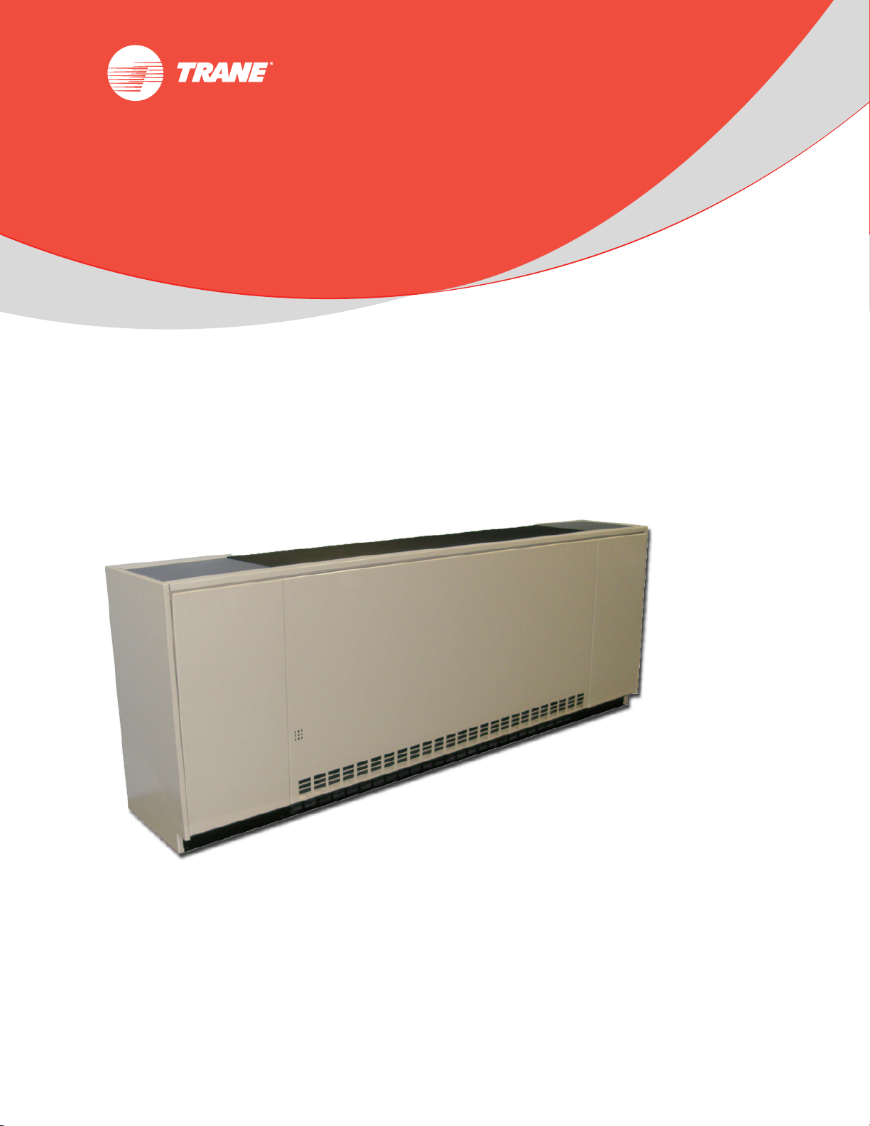
Vertical Classroom Unit Ventilator
750 cfm to 1500 cfm
June 2013 UV-PRC003-EN
Introduction
Roomy end-pockets for
install-ability and
system customization
Maintenance-free
EC motor with
direct-drive fans
Blow-through design provides
freeze protection, sound
attenuation, and safety
Hassle-free
piping
Auxiliary drain
pan option
Sealed coil, but quickly
accessed for cleaning
and visual inspection
Larger fans for
lower sound levels
Off-the-shelf
filter sizing
Linkage-free
outside air damper
The Trane Classroom Unit Ventilator
Academic performance of U.S. students depends, in part, on the ability to create a comfortable
learn-friendly surrounding. Being too hot or too cold could hinder a students ability to achieve
academic excellence.
Seasonal changes, mechanical/building disrepair, and even class attendance provide real
challenges to HVAC mechanical systems. The only thing consistent about today’s classroom is its
ability to constantly change. With this in mind, Trane introduces a NEW classroom unit ventilator
design to support today’s changing environment.
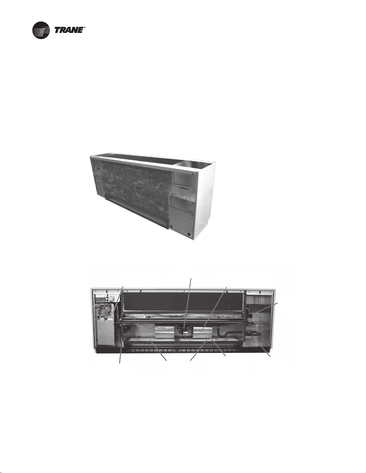
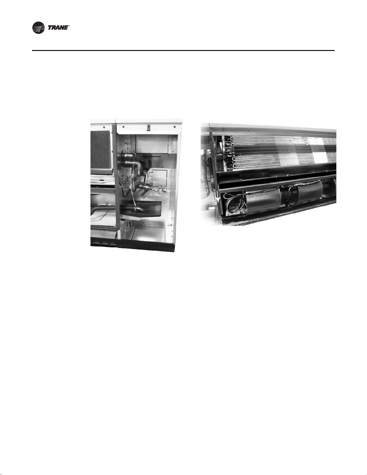
Figure 1. Back view of unit ventilator
Figure 2. Vertical classroom unit ventilator
© 2013 Trane All rights reserved UV-PRC003-EN
Introduction
Trademarks
EarthWise, Integrated Comfort, Rover, Trane, the Trane logo, TOPSS, Tracer, and Tracer Summit are
trademarks or registered trademarks of Trane in the United States and other countries. All
trademarks referenced in this document are the trademarks of their respective owners.
BACnet is a registered trademark of American Society of Heating, Refrigerating and AirConditioning Engineers (ASHRAE); Echelon, L
trademarks of Echelon Corporation.
ONMARK, LonTalk, and LONWORKS are registered
UV-PRC003-EN 3

Table of Contents
Features and Benefits . . . . . . . . . . . . . . . . . . . . . . . . . . . . . . . . . . . . . . . . . . . . . . . . . . . 5
Fit and Finish . . . . . . . . . . . . . . . . . . . . . . . . . . . . . . . . . . . . . . . . . . . . . . . . . . . . . . 5
Install-ability, Service-ability and Maintain-ability . . . . . . . . . . . . . . . . . . . . . . 5
IAQ Features . . . . . . . . . . . . . . . . . . . . . . . . . . . . . . . . . . . . . . . . . . . . . . . . . . . . . . 7
Acoustics . . . . . . . . . . . . . . . . . . . . . . . . . . . . . . . . . . . . . . . . . . . . . . . . . . . . . . . . . 8
Application Considerations . . . . . . . . . . . . . . . . . . . . . . . . . . . . . . . . . . . . . . . . . . . . . 10
A Choice in System Design . . . . . . . . . . . . . . . . . . . . . . . . . . . . . . . . . . . . . . . . . 10
Selection Procedure . . . . . . . . . . . . . . . . . . . . . . . . . . . . . . . . . . . . . . . . . . . . . . . . . . . 21
Model Number Descriptions . . . . . . . . . . . . . . . . . . . . . . . . . . . . . . . . . . . . . . . . . . . . 23
General Data . . . . . . . . . . . . . . . . . . . . . . . . . . . . . . . . . . . . . . . . . . . . . . . . . . . . . . . . . . 25
Performance Data . . . . . . . . . . . . . . . . . . . . . . . . . . . . . . . . . . . . . . . . . . . . . . . . . . . . . 28
Controls . . . . . . . . . . . . . . . . . . . . . . . . . . . . . . . . . . . . . . . . . . . . . . . . . . . . . . . . . . . . . . 64
Fan Speed Switch . . . . . . . . . . . . . . . . . . . . . . . . . . . . . . . . . . . . . . . . . . . . . . . . . 66
Customer Supplied Terminal Interface (CSTI) . . . . . . . . . . . . . . . . . . . . . . . . . 68
Tracer ZN520 Zone Controller . . . . . . . . . . . . . . . . . . . . . . . . . . . . . . . . . . . . . . 69
Tracer UC400 . . . . . . . . . . . . . . . . . . . . . . . . . . . . . . . . . . . . . . . . . . . . . . . . . . . . . 72
Zone Sensors . . . . . . . . . . . . . . . . . . . . . . . . . . . . . . . . . . . . . . . . . . . . . . . . . . . . 74
Valves/Piping Package . . . . . . . . . . . . . . . . . . . . . . . . . . . . . . . . . . . . . . . . . . . . . 76
Jobsite Connections . . . . . . . . . . . . . . . . . . . . . . . . . . . . . . . . . . . . . . . . . . . . . . . . . . . 81
Dimensional Data . . . . . . . . . . . . . . . . . . . . . . . . . . . . . . . . . . . . . . . . . . . . . . . . . . . . . . 82
Mechanical Specifications . . . . . . . . . . . . . . . . . . . . . . . . . . . . . . . . . . . . . . . . . . . . . . 87
4 UV-PRC003-EN
Features and Benefits
Fit and Finish
Equipment Size
The vertical unit ventilator delivers from 750 cfm to 1500 cfm. It is physically sized to fit the
replacement or new construction application.
Cabinet Finish
The unit cabinetry is made of a durable industrial grade metal to withstand even the most rigorous
classrooms. A smooth/glossy, appliance grade paint treatment increases the aesthetics of the
equipment while making it durable and easy to maintain.
Access
A three panel front access of the unit ventilator is ergonomically safe for lifting/removal, and allows
speedy set up during field commissioning. This design allows for the end pocket of the unit
ventilator to be open while the fan (airside) section stays closed. The panel design supports a clean
fit and finish while providing effortless access for filter change-out.
Top access to the unit mounted fan speed/sensor option was developed with the teacher or
administrative staff in mind. Access to the sensor may be made through a lock/key, or through an
easy open door.
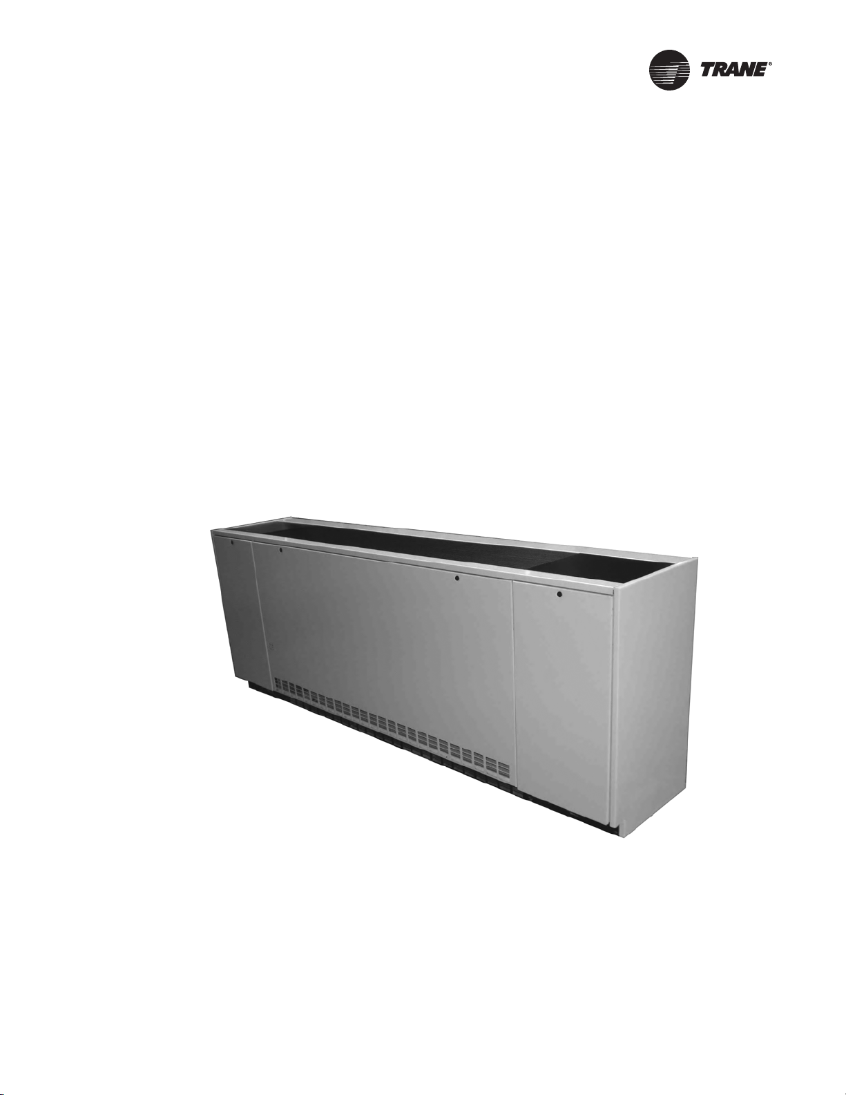
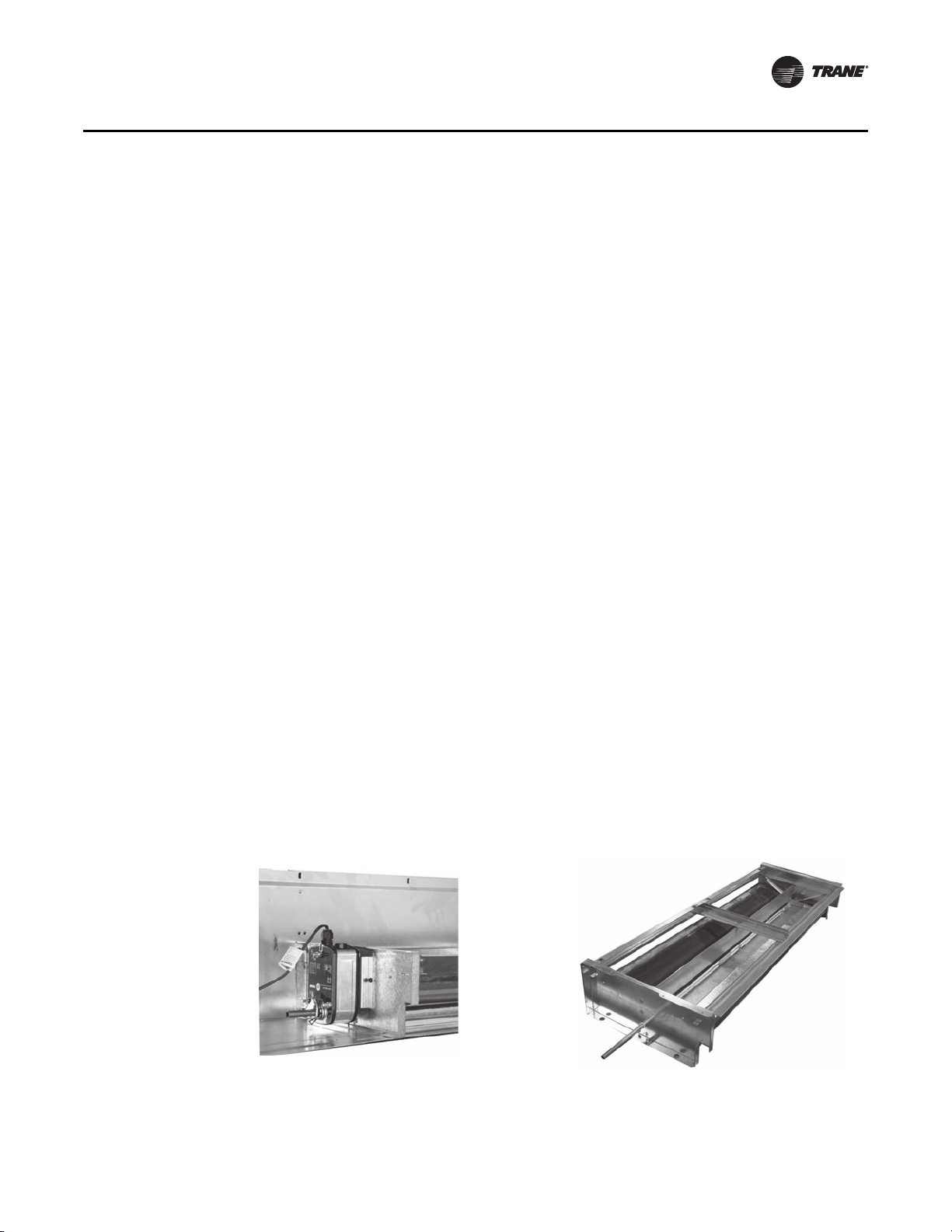
Figure 3. Fit and finish
Install-ability, Service-ability and Maintain-ability
Spacious End Pockets
Easy access to piping and controls is made through the roomy equipment end pocket design. The
coil headers and drain connections are made within the unit chassis, freeing-up valuable space in
the end pockets for piping or field add-ins. This also grants a tighter seal to prevent air leakage.
The roomy end pocket design Figure 4, p. 6 allows for application requirements such as an optional
auxiliary drain pan. The auxiliary pan may be placed under the factory or field piping package.
UV-PRC003-EN 5
Features and Benefits
Sliding Fan Deck
Convenient access to the fan motor and fan wheels for maintenance and serviceability is made in
part of the easy-slide design of the unit ventilator fan board, Figure 5. The fan board assembly
offers hassle free access to the contractor or maintenance technician. As an added benefit, Trane’s
unit ventilator includes Electronically Commutated Motors (ECM) as standard.
Figure 4. Spacious end pockets Figure 5. Sliding fan board
Energy Efficiency
Trane has a commitment to providing premium quality products that has led to the exclusive use
of Electronically Commutated Motors (ECM) in all unit ventilator models. These brushless DC
motors incorporate the latest technology for optimized energy efficiency, acoustical abatement,
maintenance free and extended motor life. Each motor has a built-in microprocessor that allows
for programmability, soft ramp-up, better airflow control, and serial communication.
• Trane units equipped with ECMs are significantly more efficient than a Permanent Split
Capacitor (PSC) motor.
• Lower operating costs on average of 50 percent (versus a PSC motor).
• The Reduced FLA option allows units to ship with a nameplate FLA rating much lower than a
typical ECM unit.
Filters
Trane unit ventilators utilize an off-the-shelf filter design to reduce or eliminate local stocking of
filters in the school. See “General Data,” p. 25 for standard filter sizes.
Note: High efficiency options, MERV 8 and MERV 13, are available. These filters provide greater
resistance and dust holding capabilities.
Hinged Control Box
The hinged control box design maintains easy access to the electrical for connection while
supporting less potential for damage on the job site from the different construction trades.
6 UV-PRC003-EN
IAQ Features
Features and Benefits
Piping
Hydronic piping for the unit ventilator may be factory installed or field provided. It fits freely inside
the unit end pockets, supplying quick hook-up during the installing phase. The motorized valves
include a trouble-free, pop-top allowing the maintenance or service technician access to the motor
without removing the valve body from the piping package.
Indoor air quality (IAQ) has become a top priority in classroom design. Giving students a healthy
place to learn and develop is crucial in every school district. It is also crucial to maintaining the
building’s overall construction and furnishings. Several features of Trane’s unit ventilator attribute
to improved IAQ.
Removable Drain Pan
The unit ventilator drain pan is dual sloped for effective condensate removal. This non-corrosive
pan eliminates the problems associated with leaking or standing water and is removable for
cleaning.
Ease of Maintenance
Internal components such as the fan and coils are accessible for visual inspection and cleaning.
Maintaining a clean system increases the efficiency of the unit and is important to good,
sustainable indoor air quality.
This design also places the coils farther away from the outside air opening, virtually eliminating the
potential for coil freezing and the added hassles of nuisance freeze-trips.
OA/RA Damper Design
The outside/return air damper is a one-piece design which is linkage free resulting in a superior air
seal (see Figure 4, p. 6). This results in lower infiltration of outside air during off cycles thus
lowering the risk of freezing equipment in the winter or the intrusion of humid air into the building
during the summer.
OA/RA Actuator
The OA/RA actuator provides true spring return operation for positive close-off of the OA/RA
damper. The spring return system of the actuator closes the outside damper if power is lost to the
building. When ordered with factory controls, the actuator is a 3-point floating design. A 2 to 10-Vdc
actuator is available when other than Trane controls are specified.
Figure 6. OA/RA Actuator and OA insulated damper
OA insulated damper
OA/RA actuator
UV-PRC003-EN 7

Features and Benefits
Unit Filter
Each classroom unit ventilator comes equipped with a standard-size throwaway filter to support
job site installation and start-up. However, the Trane unit ventilator is designed to accommodate
the use of a MERV 8 or MERV 13 high capacity filter to provide greater filtration of airborne
contaminants.
Dehumidification
Trane unit ventilators provide a broad range of dehumidification solutions. Active humidity control
involves monitoring and managing both the dry bulb temperature and the humidity in the
classroom. With this strategy, a reheat coil is placed downstream of the cooling coil to temper
(reheat) the cold, dehumidified air leaving the cooling coil to avoid over-cooling the space. Reheat
configurations are available in a variety of coil combinations.
Alternately, the Tracer™ UC400 or Tracer ZN520 controller can be configured to automatically
reduce the fan speed at part-load conditions. This helps improve the coincidental dehumidification
performance of the unit at part-load, and also lowers sound levels. To help ensure proper
ventilation in the classroom at lower fan speeds, the controller adjusts the outside air being
supplied to the classroom.
Economizer
One big advantage of a Unit Ventilator system is the ability to provide energy savings through an
economizer cycle. During mild seasons outside air is used to provide “free” cooling, thereby,
minimize or eliminate the need to run mechanical cooling equipment. To truly have an effective
economizer a Unit Ventilator must be able to bring in up to 100 percent of the design airflow
through the outside air damper opening. Trane Unit Ventilators are tested and certified to exceed
the industry standard, as defined by AHRI 840, for economizer effectiveness. This ensures the
school will realize the energy savings available through the economizer strategy.
Acoustics
Face and Bypass Actuator
The face and bypass damper actuator incorporates a direct couple design. It provides electronic
protection against overload. A limit switch is not included, nor required as part of the design. When
reaching the damper end position, the actuator automatically stops. The gears can be manually
disengaged with a button on the housing.
Quiet systems are extremely important in today’s classrooms. Trane offers many different system
solutions to balance the requirements of sound, cost, IAQ and efficiency. The Trane vertical unit
ventilator takes a comprehensive approach to delivering one of the quietest units available.
Fan and Blower Motor Assembly
Several innovative ideas have gone into the quiet design of the Trane vertical unit ventilator. The
fans diameters have been maximized to reduce the motor rpm and thus lower the noise, while still
maintaining the cfm requirements to support ventilation and capacity requirements. The unique
direct-drive fan and blower design diminishes vibration from occurring further ensuring quiet
operation.
Fan Speed Control
Trane provides the capability to vary airflow for suitable applications either with three speeds or
with a 0–10 Vdc input. This lowers the sound in the space and improves the dehumidification in the
cooling season at part-load. With field installed controls, this is accomplished with a unit-mounted
manual fan speed switch (allowing either 2- or 3-speed control) or variable speed control with a
0–10 Vdc input. ECM controls provide a soft ramp between speed changes—a significant
contributor to overall quiet operation.
8 UV-PRC003-EN

Features and Benefits
With the inclusion of the Tracer UC400 unit controller, the speed of the fan is infinitely varied
automatically in response to the load condition in the space. The controller also will adjust the
outside air being provided to properly ventilate the classroom at the lower airflow conditions.
Quiet Blow-Through Design
The Trane blow-through unit design enables additional sound attenuation by eliminating the fan
noise from entering the space directly. The position of the internal components is optimized to
enhance The performance and casing construction of Trane vertical unit ventilators further adds
to this acoustically superior design.
Certification/Standards
Comfort, energy and IAQ are all major issues that need to be woven into today’s school designs.
Therefore, it is important that designers of these systems have accurate information to make
system decisions. That is why the industry has developed performance standards and certification
programs which ensure that the equipment information provided to the design community is
correct and comparable across different manufacturers. The following list of certifications
identifies the commitment by Trane to providing the highest quality equipment and information to
our customers:
• AHRI-840
• ETL
• Tested in accordance to AHRI 350 (acoustics)
ONMARK
•L
®
UV-PRC003-EN 9

Application Considerations
A Choice in System Design
The beauty of the classroom unit ventilator goes beyond its ability to heat and cool. The unit
ventilator design provides an opportunity to create a comfortable atmosphere for living, learning
and playing, while supporting energy efficiency savings. Some of the featured benefits of a unit
ventilator are:
• Individual room control.
• Fresh air ventilation and filtration.
• Individual dehumidification sequences per zone.
• Energy savings solutions through economizing functions and Electronically Commutated
Motors.
• A choice in heating/cooling applied systems.
• And, because the equipment is mounted directly in the living space, expense associated to
installed mechanical ductwork may be avoided.
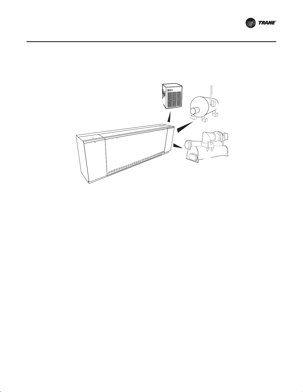
Wide Variety of Heating/Cooling Coils
Trane’s unit ventilator offers a wide variety of coil configurations to be used in many design
considerations.
In environments where cooling needs are of main interest, a two-pipe coil coupled with a chiller,
or a direct expansion coil joined with a condensing unit may be used.
For heat specific applications, Trane offers a two-pipe hot water only unit to be combined with a
boiler. Electric heat and steam options are also available for heating selections.
When there is seasonal heating and cooling, a two-pipe chilled water/hot water changeover system
may be applicable to the mechanical design. This system requires a chiller and a boiler to support
the changeover necessity. However, where space constraints may present a concern, the Trane unit
ventilator may be equipped with a direct expansion coil for cooling, with an auxiliary electric heat
coil, hot water coil, or steam coil for heating.
Four-pipe chilled water/hot water systems are also available. This system is typically applied when
both heating and cooling may be simultaneously called for in the school.
Building Automation
As part of the building automation system, the mechanical HVAC system equipment may be
optimized to lower energy consumption. By running only the mechanical devices that are required
to support the building load at a given time of day or night, true energy consumption savings may
be achieved.
Maintenance and service information through the unit sensing devices are easily defined and
cured with an automated system.
With factory shipped direct digital controls, installation and start-up of the system are more simple.
Condensate
Proper condensate trapping is required for the classroom unit ventilator’s with hydronic and direct
expansion coils (steam coils do not require a trapped condensate setup). In a properly trapped
system, when condensate forms during normal operation, the water level in the trap rises until
there is a constant flow of water through the pipe. It is imperative to maintain water in the trap, and
not allow the trap to dry out during heating season.
Equipment should be installed level to avoid condensate build-up around the coil.
Performance
Application of this product should be within the catalogs airflow and unit performance. The Trane
Official Product Selection System (TOPSS™) will aid in the selection process for a set of given
10 UV-PRC003-EN
Application Considerations
AND/OR
AND/OR
CHILLER FOR
COOLING
BOILER
FOR HEAT ADD
CONDENSER
FOR COOLING
CLASSROOM UNIT VENTILATOR
Indoor Air Quality
conditions. If this program has not been made available, ask a local Trane account manager to
supply the desired selections or provide a copy of the program.
Figure 7. System choice for the classroom unit ventilator
The Importance of Air Quality
Indoor air quality (IAQ) should be considered a top priority in the school environment. School
institutes contain a diverse day of activities that have a potential for air impurity sources including
cafeterias, art and science classrooms, vocational education areas, pools and locker rooms. Proper
ventilation and filtration of these spaces can pose some challenges.
Occupant density in classrooms is much higher than that found in office or retail spaces. The
amount of outdoor air required to ventilate a classroom is based predominantly on the number of
students expected to occupy the space. Students also move in large groups, frequently throughout
the building, resulting in widely varied thermal loads within the zones. To compound the situation,
a classroom mechanical system is typically run for 9 months of the year, and vacated for 3 months
(either by turning up or off the HVAC system). To increase the IAQ challenge even more, building
construction techniques that help reduce energy costs, also tightly seal the school. This can lead
to uncirculated/unfiltered air.
Ventilation
Ventilation is an important factor in the maintenance of healthy air. In a poor ventilated school
building, fumes and vapors are not properly exhausted allowing particles to develop. A healthier
building is a building where the air is exchanged more frequently and properly filtered. Through
ventilation, stale indoor air is exhausted and fresh treated outdoor air is drawn into the building.
The amount of ventilation air required is established by building codes and industry standards.
Most building codes reference ASHRAE Standard 62
Quality–as the minimum requirement for ventilation system design. Architects, engineers and
contractors utilize this standard when determining and calculating the type of load the building
environment will place on the mechanical system.
Trane Unit Ventilators Support Indoor Air Quality
–Ventilation for Acceptable Indoor Air
The Trane unit ventilator is tested and designed to exceed ASHRAE Standard 62. This includes the
use of a higher efficiency filtration to help introduce proper levels of “fresh” diluted air for
contaminant removal.
UV-PRC003-EN 11

Application Considerations
Energy Efficiency
Beyond the ventilation and filtration performance of the classroom unit ventilator, maintenance of
the HVAC system is a must. Several enhancements placed on the Trane unit ventilator to support
superior IAQ performance include:
• Coil presentation allows for ease of maintenance and cleaning.
• A dual sloped non-corrosive drain pan (removable) helps keep moisture in the system to a
minimum.
• Ultra low leak damper that results in a fixed air seal of the damper assembly.
• Air exchange performance that goes beyond code while maintaining the AHRI-840 certification
for economizing requirements.
• An upgrade-able MERV rated filters help reduce contaminants and increase filtration.
• Side-wall power exhaust support system to help remove the stale air from the classroom and
better support the air exchange.
• Energy recovery unit ventilator to further pretreat and dehumidify the fresh air before it enters
the classroom unit ventilator.
• Options for improved dehumidification at part-load, including automatic fan-speed control,
face and bypass dampers, and active humidity control through reheat.
A Choice in Energy Optimization
The energy consumption of a unit ventilator system can be significantly reduced through the use
of an economizer cycle. To better understand the basic function of how an outside air economizer
works, it is important to fully understand how it operates.
The economizer functions by opening an outside air damper, and bringing cooler outside air into
the space. The economizer cycle is controlled with a modulating damper motor, which opens at
specified increments dependent upon readings from outside air sensors.
Economizers also utilize a return-air damper that closes as the outside air damper opens.
Depending on the room requirements, the modulating damper motor may mix the return air with
the outside air to provide the maximum energy cost efficiencies without sacrificing comfort.
When the room thermostat calls for cooling, the economizer control provides the right mix of
outside and return air to cool the classroom. The equipment’s airflow is generated from both fan
energy and the economizing dampers. This design supports optimum ventilation and provides the
greatest energy savings. As the outside air temperature rises (typically above 55°F), the outside
damper closes to the minimum position, activating the second cooling stage on the room
thermostat—the cooling-generating device (compressor, water pump, chiller, cooling tower). The
return-air and outside air dampers modulate to support the discharged air temperature.
Dampers working together with the cooling coil is called integrated economizing, which allows a
unit ventilator to mix outside air with return air, delivering an energy-efficient, cost-savings
solution to a school.
Industry Standards
The Air-Conditioning, Heating, and Refrigeration Institute (AHRI) created the AHRI-840 standard for
classroom unit ventilators to provide a consistent method of rating the unit ventilators design
performance. To achieve AHRI-840 certification, the unit ventilator must be capable of providing a
minimum of 80 percent of its ventilation (airflow) through the outside air economizer function (see
Figure 8). This measurement ensures that the expected energy savings by the economizer is
realized in actual operation.
Only AHRI-840 certified equipment has been independently tested for compliance to the minimum
requirement. Trane was the first, and continues to be one of the few manufacturers that meet this
certification. By meeting this certification, the designer can be assured that the Trane unit ventilator
will perform with energy conservation in mind.
12 UV-PRC003-EN

Figure 8. Unit ventilator economizer
Application Considerations
Acoustics
Acoustics
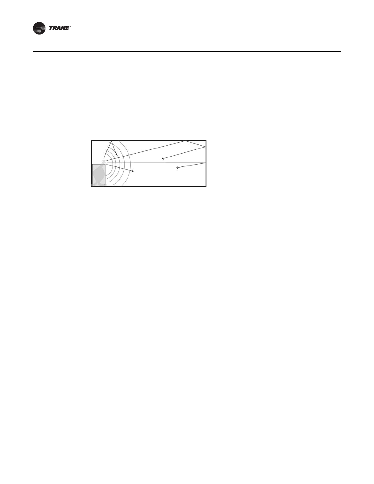
A growing population, and an increase in economic pressure to maximize building footprints have
resulted in higher building occupancies and less space to place the HVAC equipment. Often times
the close proximity of the equipment—such as a floor mounted unit ventilator—may cause noise
related complaints. Reducing the likelihood of these complaints requires careful planning:
• In the equipment sizing (under sizing and over sizing could increase noise level).
• And equipment placement (absorption and number of sound sources in the room greatly affect
noise).
Room NC is the sum of all sounds entering the room. Its value is based on assumptions about the
room’s characteristics. Given the complexity of various building systems, it is extremely important
to assure that the design goals (commissioning) for classroom acoustics, IAQ, and moisture control
are met through all aspects of the space.
For example, it is not uncommon for a school to install unit ventilators that are manufacturer-rated
for a specified airflow (cfm), but which are not AHRI-840 certified. These units may ship with a fanspeed setting that delivers a lower than specified airflow, perhaps to reduce sound levels. Without
an overall building design goal, these units will be installed without delivering the specified airflow
needed to support the fresh air circulation, and possibly compromise IAQ.
Note: Unless the equipment is tested at the specified airflow, it is extremely difficult to determine
whether the unit meets the specified sound level.
Trane’s unit ventilator will not compromise air quality to support a minor reduction in airflow noise.
We encourage our engineers to specify their airflow needs at full building load requirements. Finetuning of the speed setting may be interchanged through the unit’s 3-speed fan sensor quickly and
easily. This mechanical feature ensures that the equipment supplies proper cfm to support IAQ in
the classroom, while giving complete control of equipment noise to the administrative staff.
Technology that Supports Acoustic Enhancements
Another solution to airflow noise is through Trane direct digital controls (Tracer UC400). With the
Tracer UC400 controller, an infinitely variable speed fan control for the unit ventilator delivers the
airflow output customized to support the cfm space needs. When less cfm is necessary to meet the
UV-PRC003-EN 13
Application Considerations
Ventilation
load of the classroom, the equipment operates at an optimum speed, keeping sound levels to a
minimum. Another solution for acoustically sensitive application is the option for “Low Acoustics,”
which uses the ECM technology to manage the fan speeds. However, if the room temperature rises
above the setpoint, the controller will switch to high speed for sustaining the space needs. As part
of this strategy, ventilation must also be considered. The Tracer UC400 controller will reposition
the outside air damper to confirm the minimum outside air cfm is met at both operating conditions.
This setup allows the unit ventilator to meet the space comfort condition, while providing a lower
sound level and proper ventilation.
Figure 9. Equipment placement
Ventilation for Acceptable IAQ
Supplying proper ventilation to a classroom is challenging. The various rooms that make up a
school are forever changing in their proper ventilation needs. Building occupants and their
activities generate pollutants that heighten the ventilation requirements. And because of this
intermittent occupancy, the ventilation frequency of a classroom is constantly on the move.
Ventilation systems dilute and remove indoor contaminants, while mechanical heating and cooling
systems control the indoor temperature and humidity. Supplying an adequate amount of fresh air
to an occupied classroom is necessary for good indoor air quality. IAQ should be considered a top
priority in the school environment because children are still developing physically and are more
likely to suffer the consequences of indoor pollutants. For this reason, air quality in schools is of
particular concern. Proper conditioning of the indoor air is more than a quality issue; it
encompasses the safety and stewardship of our investment in the students, staff and facility.The
beauty of a classroom unit ventilator is its ability to provide heating, cooling, ventilation and
dehumidification as a single-zone system.
ASHRAE Control Cycles
There is a variety of control systems available today in unit ventilators. The exact method of
controlling the amount of outside air and heating capacity can vary. However, all systems provide
a sequence of operation designed to provide rapid classroom warm-up and increasing amount of
ventilation air to offset classroom load.
To help supply proper ventilation to these fluctuating heat gains, the Trane unit ventilator is
designed to provide rapid classroom warm-up and increasing amounts of ventilation air to offset
classroom overheating.
14 UV-PRC003-EN
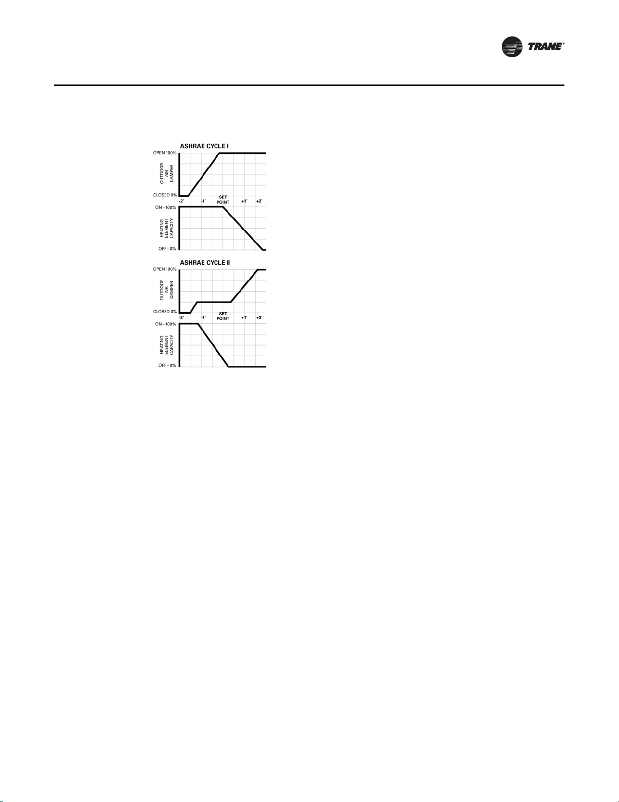
Figure 10. ASHRAE Cycle graph
Application Considerations
Ventilation
ASHRAE Cycle I
All standard unit ventilator cycles automatically close the outside air damper whenever maximum
heating capacity is required. As room temperature approaches the comfort setpoint, the outside
air damper opens fully, and the unit handles 100 percent outside air. Unit capacity is then controlled
by modulating the heating element capacity.
ASHRAE Cycle I is typically used in areas where a large quantity of outdoor air is required to offset
the air being exhausted to relieve the room of unpleasant odors and particles.
ASHRAE Cycle II
ASHRAE Cycle II is the most widely used ventilation control. Similar to Cycle I, the outside air
damper is closed during warm-up. But with Cycle II, the unit handles recirculated air through the
return air system. As temperature approaches the comfort setting, the outside air damper opens
to admit a predetermined minimum amount of outside air. This minimum has been established by
local code requirements and good engineering practices. Unit capacity is controlled by varying the
heating output. If room temperature rises above the comfort setting, the heating is turned off and
an increasing amount of outside air is admitted until only outside air is being delivered.
ASHRAE Cycle II is a very economical control sequence often referred to as integrated
economizing. This design supports optimum ventilation and provides the greatest energy savings.
This is further proof of why AHRI-840 certification is important in minimizing energy consumption
through economizer performance.
Freeze Protection
The most important advantage the Trane blow-through design provides is additional protection
against coil freeze-up. In contrast, draw-through configurations allow little mixing of the return and
outside air stream while locating the coil very close to the outside air inlet. This process creates
“cold spots” on the coil which could lead to coil freeze-up.
With a blow-through design, face and bypass with isolation valve control is not necessary to
provide proper freeze protection to the unit vent. The placement of the coil above the fan allows
enough space for the coil to avoid “cold spots” that could cause freezing.
UV-PRC003-EN 15
Application Considerations
Dehumidification
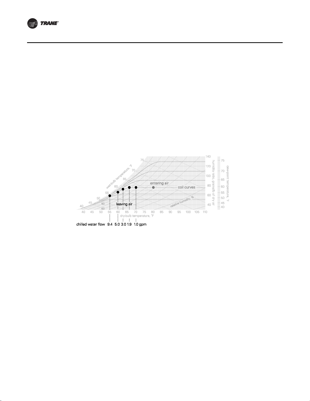
Constant Volume System
A typical unit ventilator is a constant-volume, variable-temperature device. It uses a constant fan
speed and modulates water flow through a chilled water coil to maintain the dry bulb temperature
in the space based off of a setpoint. Outdoor air is introduced at the back of the unit ventilator, and
distributed with the supply air. At design cooling load conditions, a system controlled in this
manner typically has a leaving air temperature that is cold enough (and, therefore dry enough) to
sufficiently dehumidify the space, but its ability to dehumidify can decrease significantly at partload conditions.
When the sensible load in the space decreases (part-load), the constant-volume system responds
by raising the dry-bulb temperature of the supply air. In a chilled water unit ventilator, this is
accomplished by modulating a valve to reduce the rate at which water flows through the coil.
Figure 11 shows how this affects the supply air leaving the coil—the warmer coil surface that results
from less water flow provides less sensible cooling (raising the supply air temperature) and
removes less moisture from the passing air stream.
Figure 11. Part-load dehumidification with modulated chilled water
The sensible cooling capacity of a constant volume system decreases to match the smaller sensible
cooling load. Any latent cooling (dehumidification) capacity is purely coincidental, whether the
cooling-coil medium is chilled water or refrigerant. As the load diminishes, the system delivers
even warmer supply air. Some dehumidification can occur in this situation, but only if the sensible
load is high enough.
Some designers attack this problem by oversizing the unit ventilators. This does not solve the
problem; in fact, it can make the situation worse. Increasing the capacity of the unit ventilator may
also require increasing the supply airflow. A higher-than-necessary supply airflow results in
warmer supply air and, in non arid climates, less dehumidification. It’s important to understand,
this is not just a unit, coil, or fan-sizing challenge. Rather, it’s an issue of properly controlling the
system in a manner provides sufficient dehumidification at all operating conditions. Proper
dehumidification with terminal units is a matter of proper control.
Active Humidity Control
A common method used to address this part-load humidity control challenge in a constant-volume
system is active humidity control through supply air tempering (reheat). Active humidity control
involves monitoring and controlling both the dry bulb temperature and humidity in the occupied
space. Whenever the space humidity is below the preset upper limit (typically 60 percent relative
humidity), the system operates just like a normal constant-volume system. However, if the space
humidity reaches or exceeds the upper limit, the cooling coil control valve is dri ven open regardless
of the need for sensible cooling in the space. The coil over-cools the air, increasing the
dehumidification capacity of the system.
With this control sequence, a reheat coil is placed downstream of the cooling coil to temper (reheat)
the cold, dry air leaving the cooling coil in order to avoid over-cooling the space. The key to cost-
16 UV-PRC003-EN

Application Considerations
Dehumidification
effectively applying an active humidity control system is to use reheat only when it is needed. This
requires the sensing of both the humidity and temperature in the occupied space.
When the space humidity falls below the upper limit, the system returns to the standard cooling
mode and again operates as a traditional constant-volume system.
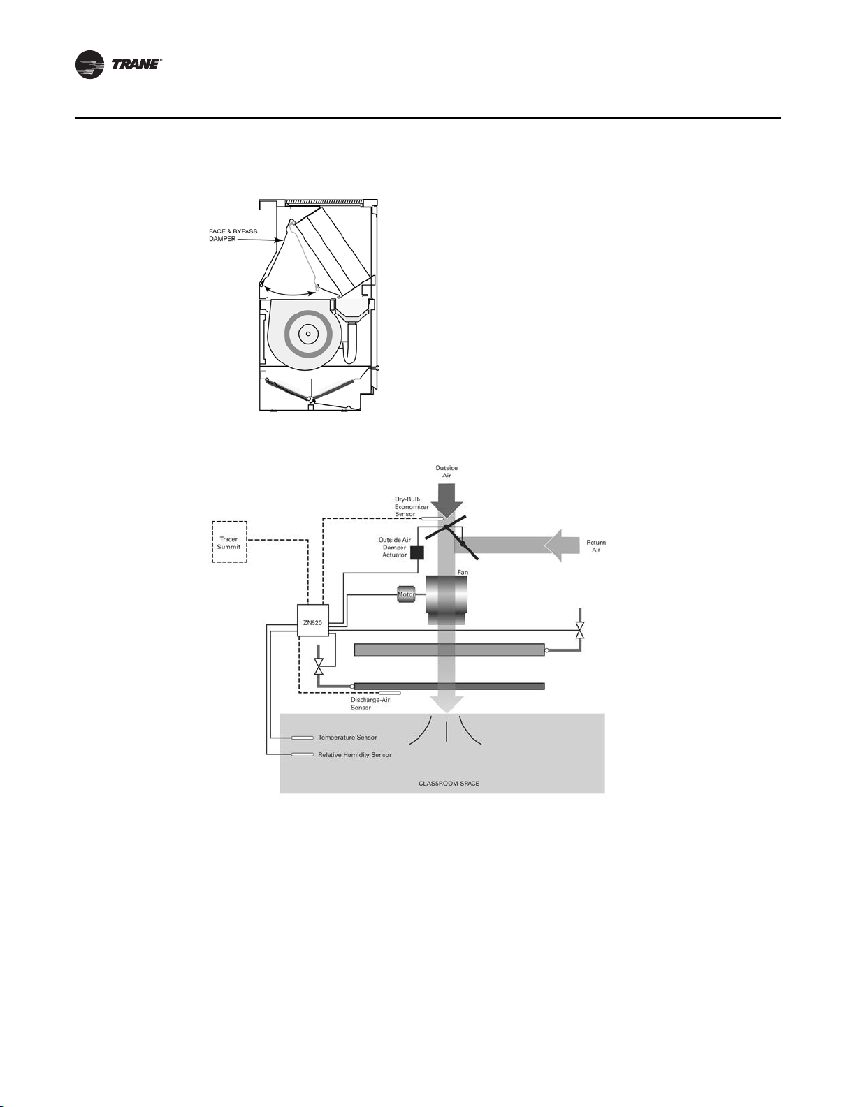
Basic components of Trane’s reheat system, include a (1) classroom unit ventilator with a main
coil and an auxiliary coil downstream, (2) the Tracer ZN520 digital controller, and (3) two
sensors, one for the temperature and one for relative humidity. Sensors may be located in the
zone, or in the return air stream.
If after hours operation is required, the addition of a building automation system (BAS) such as
Tracer Summit™ is recommended to coordinate the chillers, pumps, boiler and unit ventilators. It
also assures proper operation of the exhaust fans.
Reheat may come from new energy (electric resistance heat or boilers fueled by gas or oil) or
recovered energy.
Recovered energy reheat refers to the process of salvaging or transferring energy from another
process within the facility. In this case, the recovered energy is the by-product of a cooling process
which would normally be rejected or wasted. A common example may include a plate and frame
heat exchanger in the condenser water loop of a water-cooled chiller system.
Automatic Fan-Speed Adjustment
Reducing the fan speed (supply airflow) at part-load conditions is a way to improve the coincidental
dehumidification performance of a unit ventilator. The Tracer ZN520 digital controller can be
configured to automatically reduce fan speed when the sensible load is decreased, Figure 12, p. 18.
At full load, the fan operates at high speed and the control valve’s flow is wide open. As the cooling
load decreases, the controller modulates the valve to throttle the rate of chilled water flow through
the coil. At some point, based on valve position, the unit controller switches the fan to low speed.
Less airflow means that colder supply air is needed to maintain the target space temperature. The
control valve opens allowing the coil to remove more moisture from the passing air stream.
The controller will also adjust the outside air damper to help properly ventilate the classroom at
the lower fan speed condition.
Face and Bypass Dampers
Face and bypass control is a common and accepted method of capacity control.
The face and bypass damper, consists of a single blade installed immediately upstream of the
cooling coil. The bypass is sized to have the same pressure drop as the cooling coil so that a
constant air quantity can be maintained at all times during system operation.
Bypass control maintains the dry bulb temperature in the space by modulating the amount of air
flowing through the cooling coil, thus varying the supply air temperature to the space. As the face
and bypass damper begins to close some of the outside/return air mix is diverted around the coil
and mixed with air coming off the coil to obtain a supply air temperature that is proportional to the
reduction in space load. Because the chilled water valve remains wide open, the portion of the air
passing through the coil is dehumidified further, improving part-load dehumidification.
However, face and pass control does not actively control space humidity. It still allows the space
humidity level to rise at part-load, often higher than desired.
For more information on various methods for improving dehumidification performance of unit
ventilator systems, refer to Trane “Dehumidification in HVAC Systems” application manual
SYS-APM004-EN.
UV-PRC003-EN 17
Application Considerations
Dehumidification
Figure 12. Face and bypass damper
Figure 13. Basic components of active dehumidification control
18 UV-PRC003-EN
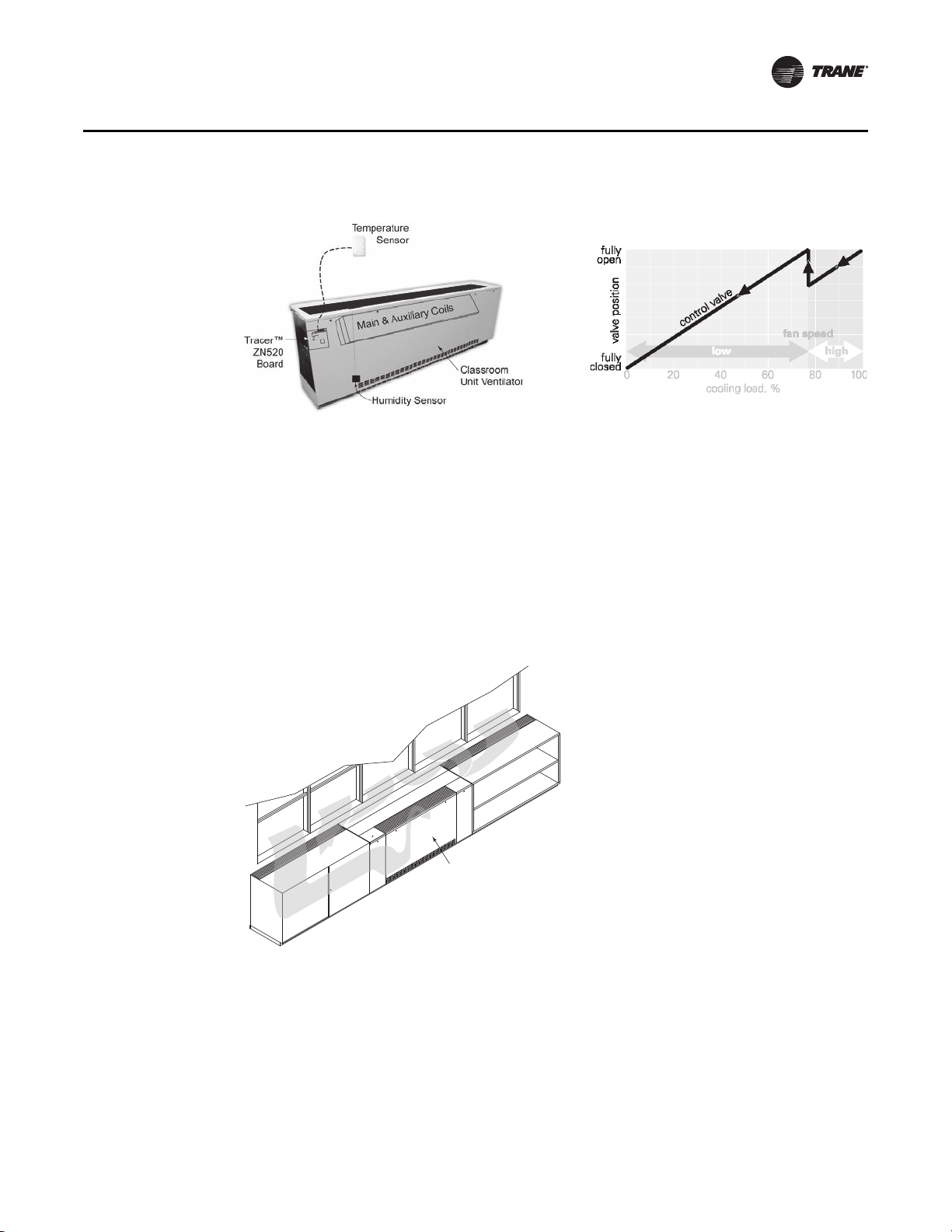
Figure 14. Reheat system and auto fan speed adjustment
Auto Fan Speed Adjustment with Tracer ZN520
Reheat System
Unit Ventilator
Captured
Cold Air
Dynamic Air Barrier
In areas that contend with colder climates for a significant period of time, a school may wish to
employ a dynamic air barrier package. With this dynamic (draft) barrier system, the cold air is
captured off of the window, and drawn into the classroom unit ventilator’s normal airflow cycle.
The unit ventilator treats/warms the air as if it were part of a return-air makeup system. This
captured air is then discharged into the space providing comfort to the classroom’s occupants.
This draft barrier shield should be utilized when:
• Almost 50 percent of the wall includes windows.
• Outside air temperatures fall below 35°F for a significant period of time
• Or, in retrofit applications where the windows are of a single pane thickness.
Application Considerations
Draft Barrier and OA Preconditioning
Figure 15. Dynamic air barrier
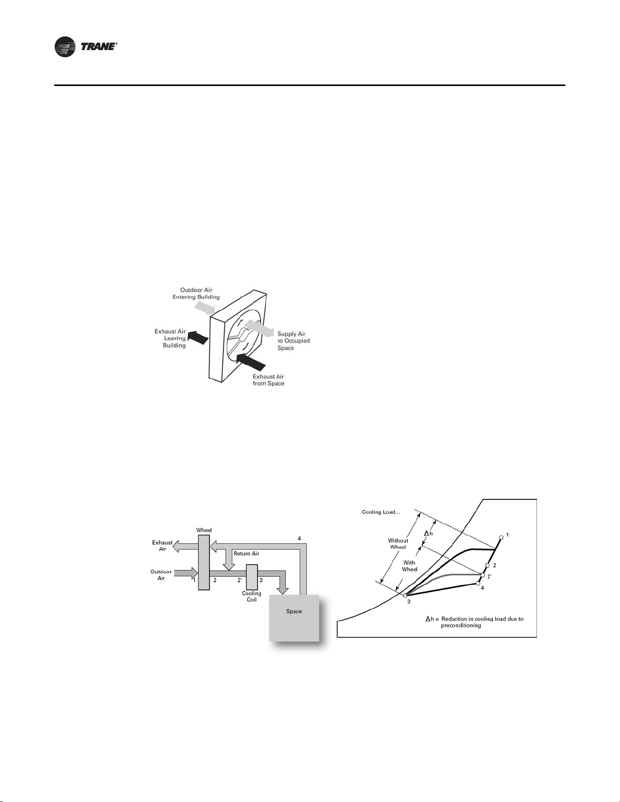
Outdoor Air Preconditioning
Conditioning the large amounts of outdoor air required for proper classroom ventilation can
significantly increase building cooling and heating loads. It also raises the system’s first cost and
operating cost. One way to reduce the impact of the outdoor air load on the unit ventilator is to use
energy recovered from the exhaust air stream to precondition the outdoor air as it’s brought into
the building.
A total-energy recovery (enthalpy) wheel consists of a revolving cylinder filled with a desiccantcoated medium suitable for sensible and latent (moisture) heat transfer, Figure 16, p. 20. The
UV-PRC003-EN 19
Application Considerations
Draft Barrier and OA Preconditioning
adjacent outdoor and exhaust air streams pass through the wheel in a counterflow arrangement
that transfers energy from one air stream to the other.
During the cooling season, the drier, sensible heat and moisture transfer from the outdoor air to
the cooler, drier exhaust air. Conversely, during the heating season, sensible heat and moisture
transfers from the exhaust air to preheat and humidify the entering outdoor air stream. Figure 16
psychrometric ally depicts the impact of a preconditioning total-energy wheel on a unit ventilator.
This approach can’t directly control humidity in the space, but it can significantly reduce the
capacity (and operating cost) of the cooling and heating equipment required to condition the
outdoor air. Capable of recovering 65 to 75 percent of the energy in the exhaust air stream, totalenergy wheels used in conjunction with unit ventilators can be an attractive alternative when
upgrading existing classroom to meet ASHRAE’s ventilation requirements; they reduce, perhaps
even eliminate, the extra capacity needed at the chiller plant or boiler.
Figure 16. Energy recover wheel
The Trane ERS energy recovery unit ventilator is one example of a “cold coil” unit with outdoor
air preconditioning.
Note: Both preconditioning (energy recovery) and post conditioning (reheat) may be applied in
the same system.
For more information on outdoor-air preconditioning and energy recovery, refer to the Trane
application engineering manual, Air-to-Air Energy Recovery in HVAC Systems (SYS-APM003-EN).
Figure 17. Cold coil with outdoor air preconditioning
20 UV-PRC003-EN

Selection Procedure
Trane vertical classroom unit ventilators provide air delivery and capacities necessary to meet the
requirements of modern school classrooms. They are available with the industry’s widest selection
of coils to precisely satisfy heating, ventilating and air conditioning loads with the best individual
type of system. Unit ventilator selection involves three basic steps.
• Determine the classroom/space unit cooling and/or heating loads
• Determine the unit size
• Select the coil
Capacity Required
The first step in unit ventilator selection is to determine room heating and air conditioning loads.
The calculation of this load is essential if the equipment is to be economical in first cost and
operating cost.
Adequate ventilation is mandatory in classroom air conditioning design. The amount is often
specified by local or state codes and, in air conditioned schools, may be either the same or less than
that specified for heating systems. The usual requirement is between 15 and 25 cfm of outside air
per occupant, based on the intended use of the room. For instance, a chemistry laboratory normally
requires more ventilation for odor control than a low occupancy speech clinic.
Ventilation is an important concern and should be accurately determined to assure good indoor air
quality. Purposely oversizing units should be avoided, since it can cause comfort and control
issues.
Unit Size
Unit ventilator size is determined by three factors:
• Total air circulation
• Ventilation cooling economizer capacity required
• Total cooling or heating capacity required
Total air circulation, if not specified by code, should be sufficient to ensure comfort conditions
throughout the room. This is usually from six to nine air changes per hour, but can vary with room
design and exposure. Often rooms with large sun exposure require additional circulation to avoid
hot spots.
Ventilation cooling capacity is determined by the amount of outside air delivered with the outside
air damper fully open, and the temperature difference between the outside air and the classroom.
In air conditioning applications, ventilation cooling capacities should maintain the comfort setting
in the classroom whenever the outside air temperature is below the unit or system changeover
temperature.
UV-PRC003-EN 21

Selection Procedure
Example:
Ventilation cooling capacity = 1.085 x cfmt x (T1 - T2)
cfm
T
T
In classrooms with exceptionally heavy air conditioning loads, unit size may be determined by the
total cooling requirement. Good practice dictates 375 to 425 cfm per ton of hydronic cooling
capacity. Normally, however, Trane classroom air conditioner coils have sufficient capacities.
Example:
Given: Air circulation specified = 8 air changes per hour.
Classroom size = 35 ft long x 25 ft wide x 10 ft high
Inside design air temperature = 75 degrees F
Ventilation cooling required at 58 degrees F = 29,000 BTU
CFM required = 8 changes/hr x (35 x 25 x 10)ft
Checking ventilation cooling capacity:
29,800 BTU = 1.085 x CFM x (80-58)
CFM = 1250
This indicates that a 1250 cfm unit would have satisfactory ventilation cooling capacity at the
design changeover point of 58°F. Coil capacity will become confirmed when the coil is selected.
= Total air capacity of unit with outside air damper open 100 percent.
t
= Room temperature.
1
= Outside air temperature.
2
3
= 1170 cfm
60 Minutes/hr
Coil Selection
Selecting the correct coil is done through Trane’s Official Product Selection System (TOPSS) For
your convenience, TOPSS has a mixed air calculator built into the program.
22 UV-PRC003-EN

Model Number Descriptions
Vertical Unit Ventilator Model Number
Digits 1, 2, 3 — Unit
Configuration
VUV= Vertical Unit Ventilator
Digit 4 — Development
Sequence
E
Digits 5, 6, 7 — Nominal Airflow
075 = 750 cfm
100 = 10 0 0 cf m
125 = 1250 cfm
150 = 150 0 cfm
Digit 8 — Voltage (Volts/Hz/
Phase)
0 = 115/60/1
1 = 208/60/1
2 = 230/60/1
3 = 208/60/3
4 = 460/60/3
7 = 277/60/1
8 = 230/60/3
Digit 9 — Open Digit
Digits 10, 11 — Current Design
Sequence
Digit 12 — Face & Bypass
Y = Yes, Include Damper
N= No Damper
Digit 13 — Unit Arrangement
1 = Return Air Front / Fresh Air Back
2 = 100% Return Air Front
3 = 100% Fresh Air Back
4 = Dynamic Air Barrier
5 = ERS-Compatible w/RH
Connection
6 = ERS-Compatible w/LH Connection
Digit 14 — Preheat / Reheat /
Changeover
A = 4-Pipe Preheat (RH Clg/LH Htg)
B = 4-Pipe Preheat (LH Clg/RH Htg)
C = 4-Pipe Reheat (RH Clg/LH Htg)
D = 4-Pipe Reheat (LH Clg/RH Htg)
E = 2-Pipe (RH Connections)
F = 2-Pipe (LH Connections)
Digit 15 — Cooling / 2-Pipe Coil
0=None
B = 2-Row, 12 F.P.I.
C = 2-Row, 16 F.P.I.
D = 3-Row, 12 F.P.I.
E = 3-Row, 16 F.P.I.
F = 4-Row, 12 F.P.I.
G = 4-Row, 14 F.P.I.
H = 3-Row, 16 F.P.I, EarthWise™ Coil
J = 3-Row, DX (R-410A) Cooling Coil
Digit 16 — Heating Coil
0=None
A = 1-Row, 12 F.P.I.
B = 2-Row, 12 F.P.I.
C = 2-Row, 16 F.P.I.
D = 3-Row, 12 F.P.I.
E = 3-Row, 16 F.P.I.
F = 4-Row, 12 F.P.I.
G = 4-Row, 14 F.P.I.
H = 3-Row, 16 F.P.I, EarthWise Coil
K=Steam Low
L=Steam High
M = Electric Heat - Low
N = Electric Heat - Med
P = Electric Heat - High
Digit 17 — Motor
0 = Electronically Commutated Motor
(ECM)
1 = ECM & Low Acoustic Option
2 = ECM & Low FLA Option
3 = ECM & Low Acoustic & Low FLA
Option
Digit 18 — Other Motor Items
A= None
B = Toggle
C = Circuit Breaker
Digit 19 — 2- or 3-Way Valve Cooling Changeover Coil
0=None
2 = 2-Way; 3-Point Floating
3 = 3-Way; 3-Point Floating
4 = 2-Way; 2–10 Volt
5 = 3-Way; 2–10 Volt
6 = Isolation Valve; 2-Way
7 = Isolation Valve; 3-Way
Digit 20 — CV - Cooling or
Changeover Coil
0=None
L=Low Cv
M= Medium Cv
H= High Cv
Digit 21 — 2- or 3-Way Valve Preheat or Reheat Heating Coil
0=None
2 = 2-Way; 3-Point Floating
3 = 3-Way; 3-Point Floating
4 = 2-Way; 2–10 Volt
5 = 3-Way; 2–10 Volt
6 = Isolation Valve; 2-Way
7 = Isolation Valve; 3-Way
Digit 22 — CV - Preheat or
Reheat Heating Coil
0=None
L=Low Cv
M= Medium Cv
H= High Cv
Digit 23 — Discharge
Arrangement
0 = Opening Only, No Grille
A = Discharge Grille
B = Double Deflection Discharge
Grille
C = Grille Discharge with Wire Mesh
Digit 24 — Outside Air Damper
Control
0=None
A = 3-Wire Actuator
B = 2–10 Volt Actuator
Digit 25 — Face and Bypass
Damper Control
0=None
A = 3-Wire Actuator
B = 2–10 Volt Actuator
Digit 26 — Controls
0 = None, Unit-Mounted Speed
Switch
2 = Customer Supplied Terminal
Interface (CSTI)
3 = CSTI w/Low Temp Detection
4 = Tracer ZN520
5 = Tracer ZN520 w/Time Clock
6 = Tracer ZN520 with w/Fan Status
7 = Tracer UC400
8 = Tracer UC400 w/Time Clock
Digit 27 — Unit- or Wall-Mounted
Controls
0=None
1 = Unit-Mounted
2 = Wall-Mounted
3 = Unit-Mounted Fan Speed
Switch & Wall-Mounted
Temperature Sensor
4 = Wireless Zone Sensor
Note: The wall-mounted room sensor is
ordered as separate line item.
Digit 28 — Internal or External
Set Point
0=None
2=External
3 = Digital Display
Digit 29 — Timed Override
0=No
1=Yes
Digit 30 — Exhaust Control
A = No Exhaust Control with 3-Speed
Supply Fan
B = Exhaust Control with 2-Speed
Supply Fan
Digit 31 — Control Programming
(Sensor Included)
0=None
1 = Humidity Sensor Programming
2=CO
Sensor Programming
2
UV-PRC003-EN 23

Model Number Descriptions
Digit 32 — Unit Depth
A = Standard (16-5/8 in.)
B = 21-1/4 in. Depth with Baffle
C = 21-1/4 in. Depth with Full Sheet
Metal Back and Baffle
D = 21-1/4 in. Depth with 25 in. High
Falseback
E = 21-1/4 in. Depth with 26 in. High
Falseback
F = 21-1/4 in. Depth with 27 in. High
Falseback
G = 21-1/4 in. Depth with 28 in. High
Falseback
H = 21-1/4 in. Depth with 29 in. High
Falseback
J = 21-1/4 in. Depth without Baffle
Note: Selection “J” should be applied if
OA opening is raised above
standard baffle location.
Digit 33 — End Covers
0=None
1 = 16-5/8 in. Depth without Cutouts
2 = 16-5/8 in. Depth with 3 x 7-1/4 in.
Cutout
4 = 21-1/4 in. Depth without Cutouts
5 = 21-1/4 in. Depth with 3 x 7-1/4 in.
Cutout
6 = 21-1/4 in. Depth with 3-1/4 in. x
16-7/8 in. Cutout
Digit 34 — Front Panel
1 = Standard Front Panel
2 = Heavy Gauge Front Panel
Digit 35 — Subbase
0=No Subbase
2 = 2 in. Subbase
4 = 4 in. Subbase
6 = 6 in. Subbase
Digit 36 — Piping Package
0=None
1 = Ball Valves & P/T Ports
2 = Ball Valve & Circuit-Setter with
P/T Ports
3 = Ball Valve, Circuit-Setter with
P/T Ports & Strainer
Digit 37 — Flow Control Cooling/Changeover Coil
0=None
Digit 38 — Flow Controls Heating Coil
0=None
Digit 39 — Auxiliary Drain Pan Piping
Y = Yes, Auxiliary Drain Pan
N = No Auxiliary Drain Pan
Digit 40 — Crossover Piping
0=None
1=Internal
2 = External 1-3/8 in. Crossover
Piping
3 = External 2-1/8 in. Crossover
Piping
Digit 41 — Filter
1 = Standard Throwaway Filter
2 = MERV 8 Filter
3 = MERV 13 Filter
Digit 42 — Color
1 = Deluxe Beige
2 = Cameo White
3=Soft Dove
4 = Stone Gray
5 = Driftwood Gray
24 UV-PRC003-EN
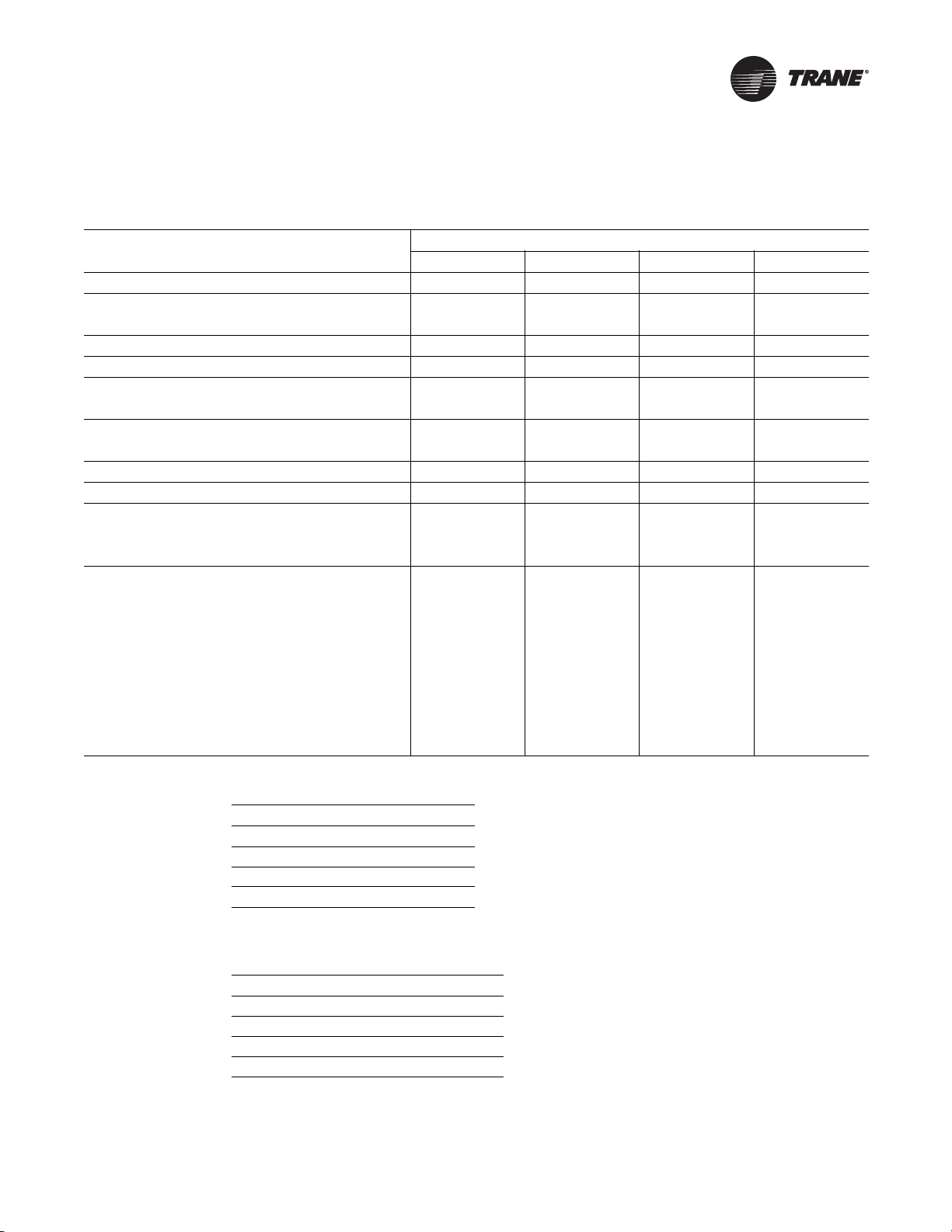
General Data
Table 1. General data
Description
Unit length without end covers (in.)
Unit depth—standard (in.)
Unit depth—with false back (in.)
Unit height—standard (in.)
Shipping weight (lb)
Nominal filter size (in.) and
quantity
Dynamic air filter nominal
size (in.) and quantity
Drain connection size (in.)
Fan type / quantity
Motor data
Quantity
Horsepower (ea.)
Coil volume (gal) by coil type
A
B
C
D
E
F
G
H
Unit size
0750 1000 1250 1500
69 81 93 105
16-5/8 16-5/8 16-5/8 16-5/8
21-1/4 21-1/4 21-1/4 21-1/4
30 30 30 30
320 405 450 470
14 x 20 x 1 (2) 14 x 24 x 1 (1) 14 x 20 x 1 (2) 14 x 24 x 1 (2)
14 x 30 x 1 (1) 14 x 24 x 1 (1) 14 x 30 x 1 (1)
7 x 42 x 1 (1) 7 x 54 x 1 (1) 7 x 66 x 1 (1) 7 x 78 x 1 (1)
7/8 ID Hose 7/8 ID Hose 7/8 ID Hose 7/8 ID Hose
FC / 2 FC / 2 FC / 4 FC / 4
1122
1/4 1/4 1/4 1/4
0.178 0.228 0.277 0.327
0.311 0.410 0.510 0.610
0.311 0.410 0.510 0.610
0.444 0.571 0.704 0.931
0.444 0.571 0.704 0.931
0.610 0.809 1.014 1.213
0.610 0.809 1.014 1.213
0.395 0.593 0.742 0.837
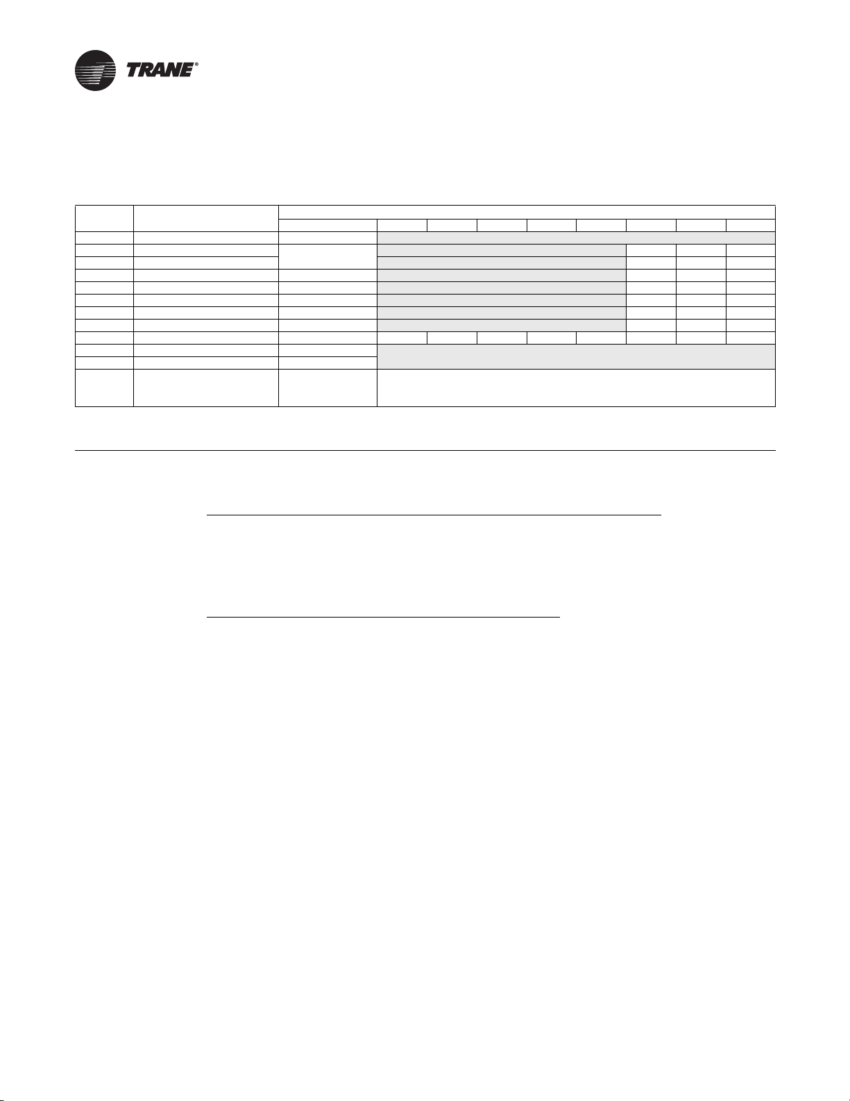
Table 2. Control methodology
Fan Speed
FSS 3 or infinite
CSTI 3 or infinite
Tracer ZN520 3
Tracer UC400 Infinite
(a)With a field-supplied 2–10 Vdc controller.
(a)
(a)
Table 3. Control sequences
Fan Speeds
(b)
(a)
(b)
(a)
1
1
2
2
DX operation
Electric heat operation
Sidewall Exhaust
ERSA
(a)Fan speed during sequence operation.
(b)Unit Ventilator when operating with option.
UV-PRC003-EN 25
General Data
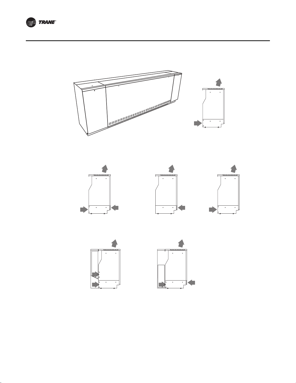
Available in:
16 5/8" Depth
21 1/4" Depth
Digit 13 = 1
RA Front with FA Back
Available in:
21 1/4" Depth
ONLY
Digit 13 = 5, 6
(5) RH Energy Recovery System
ERS Compatible
(6) LH Energy Recovery System
ERS Compatible
Available in:
16 5/8" Depth
21 1/4" Depth
Digit 13 = 2
100% Return Air Front
Available in:
16 5/8" Depth
21 1/4" Depth
Digit 13 = 3
100% Fresh Air Back
Available in:
16 5/8" Depth
21 1/4" Depth
Digit 23 = 0, A, B, C
0 = Opening Only
A = Grille Discharge
B = Double Deflection Discharge Grille
C = Discharge Grille with Wire Mesh
Available in:
21 1/4" Depth
ONLY
Digit 13 = 4
Dynamic Air Barrier
Inlet Ar
rangement
Discharge Arrangement
Discharge and Inlet Arrangements
Figure 18. Discharge and inlet arrangements
26 UV-PRC003-EN
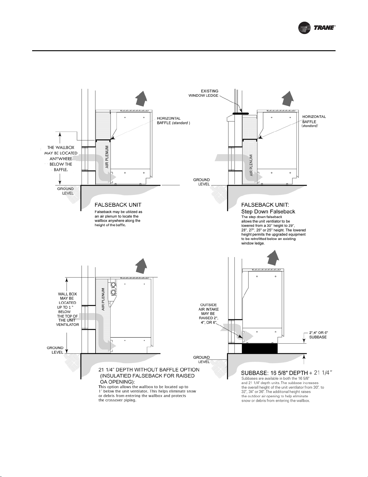
Figure 19. Falseback and subbase
General Data
Coil Combinations
UV-PRC003-EN 27
Performance Data
Table 4. Coil combination selection chart (cooling, 2-pipe changeover or heating-only coils)
Coil type Coil description
A 1-row, 12 fpi Heating only
B 2-row, 12 fpi
C 2-row, 16 fpi
D 3-row, 12 fpi
E 3-row, 16 fpi
F 4-row, 12 fpi
G 4-row, 16 fpi x
H 3-row, 16 fpi (EarthWise) x x x
J 3-row, DX (R-410A) xxxxxxxx
K Steam, low capacity
L Steam, high capacity
M Electric heat – 3-element
P Electric heat – 6-element
Notes:
1. All coil types on the left side of the grid are available in single-coil, heating only, or 2-pipe changeover with exception of coil type A.
2. For 2-coil or 4-pipe systems, select the cooling coil on the left side of the grid. An X corresponds to a valid heating coil combination.
3. Shaded areas signify valid selections with face and bypass dampers.
B and C cooling data
available in TOPSS
ABCKLMNP
x x x x xxxx
x x x x xxxx
x x x xxx
x x x xxx
x
Example 1:
4-pipe, chilled water / hot water
Type E , 3-row (16 fpi) cooling coil, may be selected with
Type B , 2-Row (12 fpi) preheat or reheat coil
Preheat or reheat coils
Heating only
Heating onlyN Electric heat – 4-element
Example 2:
4-pipe, DX cooling / steam heating
Type J , 3-row DX cooling coil, may be selected with
Type L , high-capacity steam heating coil
Notes:
• Supply and return coil connections are on the same side.
• In 4-pipe systems, the cooling coil connections are on the opposite end from the heating coil
connections.
• DX coils are always left-hand connections.
• Electric heat coils are always right-hand connections.
• Heating coils (hot water or steam) are right-hand when in the reheat position with DX cooling
coils.
28 UV-PRC003-EN
 Loading...