

Page 1

Installation
Operation &
Maintenance
Vertical and Horizontal
Classroom Unit Ventilators
Order No: UV-SVN02B-EN Date: February 2005
UV-SVN02B-EN
Page 2

2 UV-SVN001-EN
Notice
Notice
Warnings and Cautions appear at appropriate sections throughout this manual.
Read these carefully.
- Indicates a potentially hazardous situation
which, if not avoided, could result in death or
serious injury
WARNING
CAUTION
- Indicates a potentially hazardous situation
which, if not avoided, could result in minor or
moderate injury. It may also be used to alert
against unsafe practices.
CAUTION
- Indicates a situation that may result in
equipment or property damage only accidents.
Page 3

Contents
UV-SVN002-EN 3
General Information 4
Receiving and Handling 8
Installation Drawings 9
Installation 19
Location Considerations 19
Unit Mounting 20
Piping Installation 24
Valves 27
Wiring 31
Electrical Data 42
Maintenance 43
Troubleshooting 47
Accessories
Wall Boxes 49
Related Literature 52
Page 4

General Information
4 UV-SVN002-EN
Configuration
The classroom unit ventilator is configured in both a:
• horizontal (ceiling mount)
• vertical (floor mount)
configuration. The units range from 750
cfm to 2000 cfm for the horizontal configuration, and from 750 cfm to 1500
cfm for the vertical configuration.
Cabinet
The units are constructed of 14- and 16gauge zinc coated steel. All steel surfaces are cleaned, phosphatized, rinsed
and dried before application of final finish paint. The paint is applied by an
electrostatic powder spray system, minimum thickness of 1.5 mil which results
in an appliance grade finish.
Front Panels
The front panels are retained by Allen
wrench operated locks which open with
a 180-degree rotation. The vertical front
panel is constructed of either 14 or 16
gauge material dependent upon model
option selected.
End Pockets
Unit Ventilators are equipped with end
pockets to provide field installation of
valves, piping, and controls. The units
have a large pipe access opening in
both end pockets and large knockouts
for piping and electrical connections.
All electrical connections are made in
the left-hand end pocket, with exception
of units equipped with the electric heating coil option.
Drain Pan
The drain pan is positively sloped in all
planes to assure proper drainage and
help eliminate the risk of microbial
growth. To help ensure indoor air quality, the drain pan is insulated on the bottom to help prevent condensate formation. The drain pan can be easily
removed for cleaning purposes. A drain
plug is located on each end of the drain
pan on the vertical unit. The drain pan
is drilled-out and pitched toward the
cooling coil connection during assembly per model number selection.
Fanboard
The fanboard assembly is acoustically
designed in a single, rigid assembly
that includes the fans, fan housing,
bearings, fan shaft and motor. The fan
motor is mounted on the fanboard. The
fanboard is made from 14 gauge galvanized steel to resist corrosion and
increase strength.
115V Motor
The motor is a single speed permanent
split capacitor with thermal overload
protection. A multiple tap auto-transformer is wired to the motor to provide
different speed settings. The motor
speed is not affected by damper positions. Standard motors are rated up to
0.25 ESP. High static motors are rated
from 0.25 ESP to 0.45 ESP.
Motor bearings are permanently lubricated. Isolation of the motor is provided
internally at the union shaft.
Sampling Chamber (Option)
A sampling chamber is provided for
housing the room air sensor whenever
a unit mounted sensor is specified for
Tracer ZN520 controls (Figure 1). The
sampling chamber is placed below the
air-coil where room air is continuously
drawn into the chamber before being
tempered by the coil. This ensures an
accurate response to temperature
changes in the room.
Filter
Standard units are equipped with a single 1-inch thick filter that is accessible
without removal of the unit front panel.
Filter options include throw-away and
permanent renewable.
Dynamic air barrier units contain two
filters (1-standard/1-return air). The
return air filter requires front panel
removal for filter access.
OA/RA Damper
Trane unit ventilators are equipped with
dual blade type mixing damper to
ensure proper modulation and mixing
of return and outdoor air designed in
accordance to ARI 840. A splitter is
placed between the damper blades to
separate the fresh-air and return-air
compartments to prevent draft blowthrough.
An ultra low-leak damper seal is
applied on all vertical unit configurations. The seal consist of a medium
density, closed-cell neoprene material.
The seal is fixed and not part of the
damper assembly. The outside-air
damper closes into the closed cell neoprene material, providing a positive
pressure seal.
Figure 1: Sampling Chamber
Page 5

General Information
UV-SVN002-EN 5
OA/RA Actuator (Option)
The OA/RA actuator provides true
spring return operation for positive
close-off of the OA/RA damper. The
spring return system of the actuator
closes the outside damper if power is
lost to the building. When ordered with
factory mounted controls, the actuator
is 3-point floating. A 2 to 10 VDC actuator is also available when other than
Trane controls is required. See Table 1
for technical data of the OA/RA actuator.
Face and Bypass (Option)
The face and bypass option consist of
an actuator, damper blade and 2-position water valve (option).
During bypass mode, the damper
moves to prevent air from traveling
through the coil. The damper blade is
tightly sealed to eliminate heat pickup
while in the full bypass mode.
A two-position isolation valve control
(option) further enhances this system
by closing off all water flow to the coil
during full bypass operation. 2-pipe
main steam systems utilize the face and
bypass as part of the standard operation and may incorporate the optional
isolation valve.
Face and Bypass Actuator
(option)
The face and bypass damper actuator
incorporates a direct couple design for
both the horizontal and the vertical configurations. The actuator is provided
with electronic protection against overload. It does not contain, nor require a
limit switch. When reaching the damper
end position, the actuator automatically
stops. The gears can be manually disengaged with a button on the actuator
housing.
See Table 2 for technical data.
Power Supply
24VAC + 20% 50/60HZ
24VAC + 10%
Power
Consumption
Running: 2.5W
Holding: 1W
Transformer
Sizing
5VA (class 2 power source)
Overload
Protection
Electronic throughout
0 to 95-degree rotation
Control Signal
2-10 VDC
3 point floating w/ Trane controls
Rotation Angle
95-degree max.
Adjustable w mechanical stop
Torque 35-inch/lb
Rotation
Direction
Spring return reversible w/
CW/CCW mounting
Position
Indication
Visual indicator, 0 to 95-degrees
Run Time 90-second constant
Noise Level Running: 30dB
Power Supply
24VAC + 20% 50/60HZ
24VAC +
10%
Power
Consumption
2W
Transformer
Sizing
3VA (class 2 power source)
Manual Override External push button
Control Signal 3 point floating w/ Trane controls
Rotation Angle
95-degree max.
Adjustable w mechanical stop
Torque 35-inch/lb
Rotation
Direction
Reversible with switch L/R
Position
Indication
Clip-on indicator
Run Time 90-second constant
Noise Level Less than 35dB
Table 1: Technical Data for OA/RA
actuator
Table 2: Technical Data for face &
bypass actuator
Page 6

General Information
6 UV-SVN002-EN
Modulating Water Valves (Option)
The modulating control valve option
provides optimum control of hot and
chilled water flow in various heating
and cooling applications. They are
designed to provide sinusoidal valve
actuator travel and operate silently,
resisting water hammer.
The actuator on the valve is a 24V, 3point floating type. See Table 3 for more
technical data.
Isolation Valves (Option)
The isolation valves are two position
24V, spring return type. They provide
added control in heating and cooling
applications when used in conjunction
with the face and bypass damper.
On heating coils and two-pipe changeover applications, the valve is a normally open type to prevent the coil from
freezing in case of power loss.
For cooling, the valve is normally
closed and opens when there is a call
for cooling. See Table 4, for more technical data.
Power Supply 24V - 50/60 Hz
Power Consumption 4W
Maximum Duty Cycle 15%
Nominal Timing 120 sec.
Operating Ambient
Temperature
0 to 65 C
32 to 150 F
Min./Max Fluid
Temperatures
1 to 95 C
34 to 203 F
Operating Pressure
Differential
Max. - 4 bar (60 psi)
Pressure Rating
Static- 20 bar (300psi)
Burst- 100 bar
(1500 psi)
Flow Characteristics Linear
Power Supply 24V - 50/60 Hz
Power Consumption 5W
Max. Fluid Temp. 200 F/ 94 C
Min. Fluid Temp. 34 F / 1 C
Max. Operating
Pressure
300 psi
Max. Close-off
Pressure
1/2” = 30 psi
3/4” = 20 psi
1” = 15 psi
Table 3: Technical Data for
Modulating Water Valves
Table 4: Technical Data for Isolation
Water Valves
Page 7

General Information
UV-SVN002-EN 7
Unit Ventilator Controls
Controls are provided either by Trane as
a factory-mounted option or furnished
by an outside vendor and mounted at
the job-site.
Units constructed for field installation
of controls are shipped with one of the
following type of controls:
•
No Controls/Field Installation:
(Option) The unit comes equipped
with an auto transformer, fan speed
switch and damper blade only.
•
End Device Package (EDP)
:
This option pre-wires optional
control components to a terminal
strip for wiring field provided
controller and temperature sensor.
NOTE: For controller operation malfunction of any non-Trane, fieldinstalled controls, consult the literature
or technical support of the controls
manufacturer.
Trane offers Direct Digital Controls for
the unit ventilator. The ZN520 (See
Figure 2) unit controller is designed to
provide control of the classroom unit
ventilator and the fan coil products and
adds increased functionality to the unit
ventilator.
When Trane controls are ordered for an
installation, the controls are shipped
already installed and factory-tested to
ensure proper operation at start-up.
NOTE: For more details on the ZN520
unit controller option or operation and
service/replacement issues, please refer
to
CNT-SVX04A-EN:
Tracer ZN520 Unit
Controller IOP.
Automatic Controls
Regardless of type of controls, all systems provide a sequence of operation
designed to provide rapid warm-up of
the room and increase ventilation while
offsetting overheating.
In addition, air conditioning installations will usually provide a means of
system changeover from heating to
cooling as well as provisions for drawing a pre-determined amount of outside
air into the room.
Unit Switch
The unit “On-Off” switch, provided by
Trane, is typically housed in the control
box mounted in the left hand end pocket immediately below the discharge
grille.
When Trane ZN520 unit controllers are
used, the unit switch is located on the
switch module in the end pocket behind
the front panel rather than below the
grille.
Figure 2: ZN520 unit controller
Page 8

Receiving and Handling
8 UV-SVN002-EN
The unit ventilator is packaged in clear
stretch wrap and protective to allow for
immediate visual inspection. Vertical
units are also shipped with a protective
cardboard cover to help prevent
scratching and other cosmetic blemishes during transport (Figure 3).
Horizontal units are shipped with cardboard blocking on all edges for protection during shipping (Figure 4).
NOTE:
Before unwrapping, make a
visual inspection of the unit for any
damage that may have occurred during
shipping. All orders are shipped FOB
(Free on Board) from the factory, therefore any claims must be made with the
delivering carrier.
Following visual inspection, carefully
begin the following procedures:
1. Carefully remove the stretch
wrap and the top cardboard
cover.
If end covers have been
ordered for vertical units, the
panel will already be mounted to
the unit.
2. Remove remaining cardboard
blocking
3. Remove the front (vertical) or
bottom (horizontal) access
panel with a 7/32” Allen wrench.
4. Verify nameplate sales order
number is correct.
5. Remove shipping bracket from
the lower rear corners of the unit
and shipping skid. Access to the
screws holding unit to the skid is
obtained inside the unit.
6. Rotate fan wheels manually.
Wheels should move freely and
be in proper alignment. Visually
inspect the fan area for obstru-
tions or shipping damage.
7. Remove all applicable knockouts for coil piping and
electrical connections.
See
Figures 6 thru 14
Figure 3: Vertical unit ventilator as shipped.
Figure 5: Shipping skid
removal
Figure 4: Horizontal unit ventilator as
shipped.
Page 9

UV-SVN002-EN 9
Installation Drawings
VUV 15-1/4” Depth
Figure 6: Standard depth vertical unit ventilator dimensional data
Unit Size
# of Fans A B
075 2 69” 42”
100 3 81” 54”
125 4 93” 66”
150 5 105” 78”
30"
1 3/4"
1"
10 7/8"
13 1/2" 13 1/2"
1 3/4"
3/4"
(2)-10 1/2" x 7 1/4" K.O..
FOR PIPING OR
ELECTRICAL
(2)-6" x 6" K.O.
FOR PIPING
OR ELECTRICAL
OPTIONAL F.A. OPENING
B
A
BACK VIEW SIDE VIEW
(2)-9" x 9"
KNOCKOUTS
IN BOTTOM
TOP VIEW
15 1/4"
1 3/8" 2 1/2"
8 7/8"
20 1/2"
4"
4 1/8"
20"
10 7/8"
2 1/2"
1/2"
13" 2"
LEFT-HAND
END POCKET
ISO VIEW
NOTE:
UNIT LENGTH DOES NOT INCLUDE
5/8" END COVERS.
THE POWER CONNECTION IS MADE IN THE
LEFT HAND END POCKET FOR ALL OPTIONS
EXCEPT ELECTRIC HEAT. THE POWER CONNECTION
FOR ELECTRIC HEAT IS MADE IN THE RIGHT HAND
END POCKET.
NOTE:
FOR UNITS EQUIPPED WITH CROSS-
(2)-3 3/4" x 8 7/8"
CUTOUT FOR
ELECTRICAL
RIGHT-HAND
END POCKET
OVER PIPING: PIPING ENDS ARE
FLUSH WITH UNIT END AND ARE
RECESSED IN CUTOUT SPACE
PROVIDED AS SHOWN.
CROSSOVER PIPING IS EITHER
1-3/8" OD OR 2-1/8" OD.
Page 10

Installation Drawings
VUV 16-1/4” Depth
10 UV-SVN002-EN
Figure 7: 1-inch falseback vertical unit ventilator dimensional data
Unit Size
# of Fans A B
075 2 69” 42”
100 3 81” 54”
125 4 93” 66”
150 5 105” 78”
30"
(2)-10 1/2" x 7 1/4" K.O..
(2)-6" x 6" K.O.
FOR PIPING
OR ELECTRICAL
1"
10 7/8"
13 1/2" 13 1/2"
1 3/4"
1 3/4"
OPTIONAL F.A. OPENING
(2)-9" x 9"
KNOCKOUTS
IN BOTTOM
FOR PIPING OR
ELECTRICAL
B
A
BACK VIEW SIDE VIEW
TOP VIEW
16 1/4"
1 3/8" 3 1/2"
8 7/8"
20 1/2"
4"
4 1/8"
20"
10 7/8"
2 1/2"
1 1/2"
14" 2"
LEFT-HAND
END POCKET
ISO VIEW
NOTE:
UNIT LENGTH DOES NOT INCLUDE
5/8" END COVERS
THE POWER CONNECTION IS MADE IN THE
LEFT HAND END POCKET FOR ALL OPTIONS
EXCEPT ELECTRIC HEAT. THE POWER CONNECTION
FOR ELECTRIC HEAT IS MADE IN THE RIGHT HAND
END POCKET.
NOTE:
FOR UNITS EQUIPPED WITH CROSS-
(2)-3 3/4" x 8 7/8"
CUTOUT FOR
ELECTRICAL
RIGHT-HAND
END POCKET
OVER PIPING: PIPING ENDS ARE
FLUSH WITH UNIT END AND ARE
RECESSED IN CUTOUT SPACE
PROVIDED AS SHOWN.
CROSSOVER PIPING IS EITHER
1-3/8" OD OR 2-1/8" OD.
Page 11

UV-SVN002-EN 11
Installation Drawings
VUV 21-1/4” Depth
Figure 8: 6-inch falseback vertical unit ventilator dimensional data
Unit Size
# of Fans A B
075 2 69” 42”
100 3 81” 54”
125 4 93” 66”
150 5 105” 78”
30"
1 3/4"
1"
10 7/8"
13 1/2" 13 1/2"
1 3/4"
6 3/4"
(2)-10 1/2" x 7 1/4" K.O..
FOR PIPING OR
ELECTRICAL
(2)-6" x 6" K.O.
FOR PIPING
OR ELECTRICAL
OPTIONAL F.A. OPENING
B
A
BACK VIEW SIDE VIEW
(2)-9" x 9"
KNOCKOUTS
IN BOTTOM
TOP VIEW
21 1/4"
1 3/8" 8 1/2"
8 7/8"
20 1/2"
4"
4 1/8"
20"
10 7/8"
2 1/2"
6 1/2"
19" 2"
NOTE:
UNIT LENGTH DOES NOT INCLUDE
5/8" END COVERS
LEFT-HAND
END POCKET
ISO VIEW
THE POWER CONNECTION IS MADE IN THE
LEFT HAND END POCKET FOR ALL OPTIONS
EXCEPT ELECTRIC HEAT. THE POWER CONNECTION
FOR ELECTRIC HEAT IS MADE IN THE RIGHT HAND
END POCKET.
NOTE:
FOR UNITS EQUIPPED WITH CROSS-
(2)-3 3/4" x 8 7/8"
CUTOUT FOR
ELECTRICAL
RIGHT-HAND
END POCKET
OVER PIPING: PIPING ENDS ARE
FLUSH WITH UNIT END AND ARE
RECESSED IN CUTOUT SPACE
PROVIDED AS SHOWN.
CROSSOVER PIPING IS EITHER
1-3/8" OD OR 2-1/8" OD.
Page 12

12 UV-SVN002-EN
Installation Drawings
VUV Ducted Inlet
Figure 9: 6-inch falseback vertical unit ventilator with ducted inlet dimensional data
Unit Size
# of Fans A B
075 2 69” 42”
100 3 81” 54”
125 4 93” 66”
150 5 105” 78”
30"
(2)-10 1/2" x 7 1/4" K.O..
1 3/4"
(2)-6" x 6" K.O.
FOR PIPING
OR ELECTRICAL
1"
10 7/8"
13 1/2" 13 1/2"
1 3/4"
6 3/4"
F.A. OPENING INTO U.V.
FOR PIPING OR
ELECTRICAL
B
A
BACK VIEW SIDE VIEW
B
F.A. INLET
TOP VIEW
21 1/4"
1 3/8" 8 1/2"
8 7/8"
20 1/2"
4"
4 1/8"
(2)-9" x 9"
1"
4"
KNOCKOUTS
IN BOTTOM
20"
10 7/8"
2 1/2"
6 1/2"
19" 2"
LEFT-HAND
END POCKET
ISO VIEW
NOTE:
UNIT LENGTH DOES NOT INCLUDE
5/8" END COVERS
THE POWER CONNECTION IS MADE IN THE
LEFT HAND END POCKET FOR ALL OPTIONS
EXCEPT ELECTRIC HEAT. THE POWER CONNECTION
FOR ELECTRIC HEAT IS MADE IN THE RIGHT HAND
END POCKET.
NOTE:
FOR UNITS EQUIPPED WITH CROSS-
(2)-3 3/4" x 8 7/8"
CUTOUT FOR
ELECTRICAL
RIGHT-HAND
END POCKET
OVER PIPING: PIPING ENDS ARE
FLUSH WITH UNIT END AND ARE
RECESSED IN CUTOUT SPACE
PROVIDED AS SHOWN.
CROSSOVER PIPING IS EITHER
1-3/8" OD OR 2-1/8" OD.
Page 13

UV-SVN002-EN 13
Installation Drawings
VUV Ducted Inlet/Discharge
Figure 10: 6-inch falseback vertical unit ventilator with ducted inlet and return air discharge dimensional data
Unit Size
# of Fans A B
075 2 69” 42”
100 3 81” 54”
125 4 93” 66”
150 5 105” 78”
30"
(2)-10 1/2" x 7 1/4" K.O..
(2)-6" x 6" K.O.
FOR PIPING
OR ELECTRICAL
1"
10 7/8"
13 1/2" 13 1/2"
1 3/4"
6 3/4"
F.A. OPENING INTO U.V.
9"
FOR PIPING OR
ELECTRICAL
B
A
BACK VIEW SIDE VIEW
B
F.A. INLET
DISCHARGE
21 1/4"
1 3/8" 8 1/2"
8 7/8"
20 1/2"
4"
4 1/8"
(2)-9" x 9"
1"
4"
KNOCKOUTS
IN BOTTOM
20"
10 7/8"
2 1/2"
6 1/2"
19" 2"
TOP VIEW
1 1/4"
LEFT-HAND
END POCKET
ISO VIEW
NOTE:
UNIT LENGTH DOES NOT INCLUDE
5/8" END COVERS
THE POWER CONNECTION IS MADE IN THE
LEFT HAND END POCKET FOR ALL OPTIONS
EXCEPT ELECTRIC HEAT. THE POWER CONNECTION
FOR ELECTRIC HEAT IS MADE IN THE RIGHT HAND
END POCKET.
UNIT MOUNTED FAN SPEED SWITCH IS ROTATED
AND ACCESSED THROUGH THE FRONT PANEL
WHEN UNIT AIR DISCHARGE IS DUCTED.
NOTE:
FOR UNITS EQUIPPED WITH CROSS-
(2)-3 3/4" x 8 7/8"
CUTOUT FOR
ELECTRICAL
RIGHT-HAND
END POCKET
OVER PIPING: PIPING ENDS ARE
FLUSH WITH UNIT END AND ARE
RECESSED IN CUTOUT SPACE
PROVIDED AS SHOWN.
CROSSOVER PIPING IS EITHER
1-3/8" OD OR 2-1/8" OD.
Page 14

14 UV-SVN002-EN
Installation Drawings
HUV Ducted Front Discharge
Figure 11: Horizontal unit ventilator with ducted front discharge dimensional data. Sizes 075-150
Size A B C D
075 70-1/4” 36” 46” 43-1/4”
100 82-1/4” 48” 58” 55-1/4”
125 94-1/4” 60” 70” 67-1/4”
150 106-1/4” 72” 82” 79-1/4”
2 3/8"
4 7/8"
2"-DIA K.O.
FOR PIPING
F.A. UPPER BACK
R.A. LOWER BACK
B17 1/8"
A
7/8"-DIA K.O.
FOR ELECTRICAL
17 1/8"
BACK VIEW SIDE VIEW
12 1/8"
13 1/2" 13 1/2"
C
D
TOP VIEW
3"
6 1/2"
10 1/2"
11"
14 1/2"
10 1/8"
4"
1 3/4"
4"
7 1/8"
7 7/8"
16 5/8"
32 1/2"
35 5/8"
7/8" x 2" SLOTS
FOR HANGING BRACKETS
LEFT HAND
END POCKET
RIGHT HAND
END POCKET
DISCHARGE
ISO VIEW
NOTE:
WHEN ELECTRIC HEAT IS PRESENT, ALL POWER
CONNECTIONS ARE MADE IN THE RIGHT HAND
END POCKET. ON ALL OTHER CONFIGURATIONS,
POWER CONNECTIONS ARE MADE IN THE LEFT
HAND END POCKET.
Page 15

UV-SVN002-EN 15
Installation Drawings
HUV Ducted Front Discharge
Figure 12: Size 200 horizontal unit ventilator with ducted front discharge dimensional data
2 3/8"
4 7/8"
2"-DIA K.O.
FOR PIPING
F.A. UPPER BACK
R.A. LOWER BACK
72"17 1/8"
106 1/4"
7/8"-DIA K.O.
FOR ELECTRICAL
17 1/8"
BACK VIEW SIDE VIEW
12 1/8"
13 1/2" 13 1/2"
82"
72"
79 1/4"
TOP VIEW
4"
7 1/2"
11 1/2"
15 1/2"
13 1/2"
26 1/2"
39 1/2"
43 1/8"
7/8" x 2" SLOTS
FOR HANGING BRACKETS
10 1/8"
2 3/4"
5"
5"
6 1/8"
9 7/8"
17 5/8"
LEFT HAND
END POCKET
RIGHT HAND
END POCKET
DISCHARGE
ISO VIEW
NOTE:
WHEN ELECTRIC HEAT IS PRESENT, ALL POWER
CONNECTIONS ARE MADE IN THE RIGHT HAND
END POCKET. ON ALL OTHER CONFIGURATIONS,
POWER CONNECTIONS ARE MADE IN THE LEFT
HAND END POCKET.
Page 16

16 UV-SVN002-EN
Figure 13: Double deflection discharge horizontal unit ventilator dimensional data. Sizes 075 - 150
Size A B C D
075 70-1/4” 36” 46” 43-1/4”
100 82-1/4” 48” 58” 55-1/4”
125 94-1/4” 60” 70” 67-1/4”
150 106-1/4” 72” 82” 79-1/4”
Installation Drawings
HUV Bottom Double Deflection Discharge
2 3/8"
4 7/8"
17 1/8"
12 1/8"
2"-DIA K.O.
FOR PIPING
R.A. LOWER BACK
B
A
7/8"-DIA K.O.
FOR ELECTRICAL
17 1/8"
3"
6 1/2"
10 1/2"
14 1/2"
3/4"
16 5/8"
4"
10 1/8"
4"
BACK VIEW SIDE VIEW
C
B
11"
32 3/4"
46"
48 3/4"
7 1/4"
5 1/8"
13 1/2" 13 1/2"
D
TOP VIEW
7/8" x 2" SLOTS
FOR HANGING BRACKETS
BOTTOM DISCHARGE
RIGHT HAND
END POCKET
ISO VIEW
LEFT HAND
END POCKET
NOTE:
WHEN ELECTRIC HEAT IS PRESENT, ALL POWER
CONNECTIONS ARE MADE IN THE RIGHT HAND
END POCKET. ON ALL OTHER CONFIGURATIONS,
POWER CONNECTIONS ARE MADE IN THE LEFT
HAND END POCKET.
Page 17
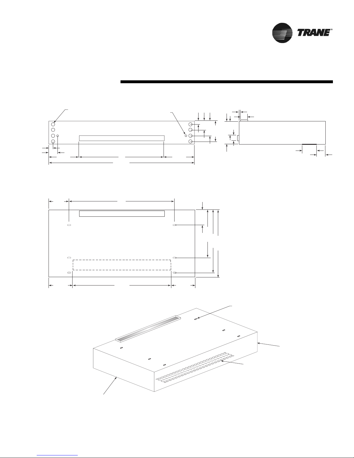
UV-SVN002-EN 17
Figure 14: Double deflection discharge horizontal unit ventilator dimensional data. Size 200
Installation Drawings
HUV Bottom Double Deflection Discharge
2 3/8"
4 7/8"
17 1/8"
12 1/8"
2"-DIA K.O.
FOR PIPING
R.A. LOWER BACK
72"
106 1/4"
7/8"-DIA K.O.
FOR ELECTRICAL
17 1/8"
4"
7 1/2"
11 1/2"
15 1/2"
3/4"
17 5/8"
5"
10 1/8"
5"
BACK VIEW SIDE VIEW
82"
13 1/2"
26 1/2"
53 3/4"
57 1/4"
9 1/4"
5 1/8"
13 1/2" 13 1/2"
79 1/4"
TOP VIEW
7/8" x 2" SLOTS
FOR HANGING BRACKETS
BOTTOM DISCHARGE
RIGHT HAND
END POCKET
ISO VIEW
LEFT HAND
END POCKET
NOTE:
WHEN ELECTRIC HEAT IS PRESENT, ALL POWER
CONNECTIONS ARE MADE IN THE RIGHT HAND
END POCKET. ON ALL OTHER CONFIGURATIONS,
POWER CONNECTIONS ARE MADE IN THE LEFT
HAND END POCKET.
Page 18
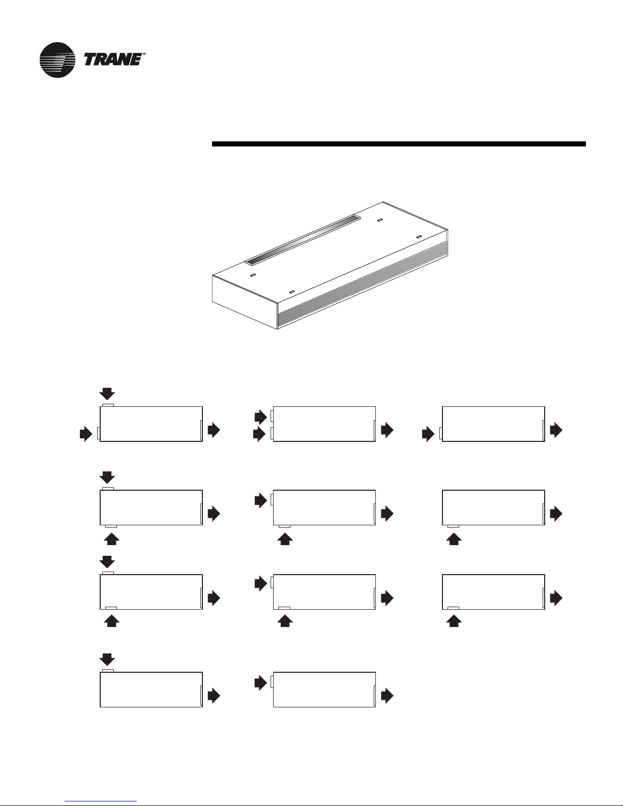
18 UV-SVN002-EN
Installation Drawings
HUV Inlet Arrangements
Figure 15: Supply/return air arrangements for the HUV
DIGIT 20 = A
FA DUCT TOP
w/RA DUCT LOWER BACK
DIGIT 20 = B
FA DUCT TOP
w/RA DUCT BOTTOM
DIGIT 20 = C & D
(C) FA DUCT TOP
w/RA BAR GRILLE BOTTOM
(D) FA DUCT TOP
w/RA OPEN BOTTOM
DIGIT 20 = E
100% FA DUCT TOP
DIGIT 20 = F
FA DUCT UPPER BACK
w/RA DUCT LOWER BACK
DIGIT 20 = G
FA DUCT UPPER BACK
w/RA DUCT BOTTOM
DIGIT 20 = H & J
(H) FA DUCT UPPER BACK
w/RA BAR GRILLE BOTTOM
(J) FA DUCT UPPER BACK
w/RA OPEN BOTTOM (no grille)
DIGIT 20 = K
100% FA DUCT UPPER BACK
DIGIT 20 = L
100% RA DUCT LOWER BACK
DIGIT 20 = M
100% RA DUCT BOTTOM
DIGIT 20 = N & P
(N) 100% RA BAR GRILL BOTTOM
(P) 100% RA OPEN BOTTOM
(no grille)
Page 19
UV-SVN002-EN 19
Installation
Location Considerations
Selecting the appropriate location for
installing a unit is very important. The
following factors should be considered:
Vertical Unit Ventilators
1. Floor design must have sufficient
structure to withstand the weight
of the unit while allowing for
openings in the floor for a Return
Air duct, electrical and piping
supply lines fed through the
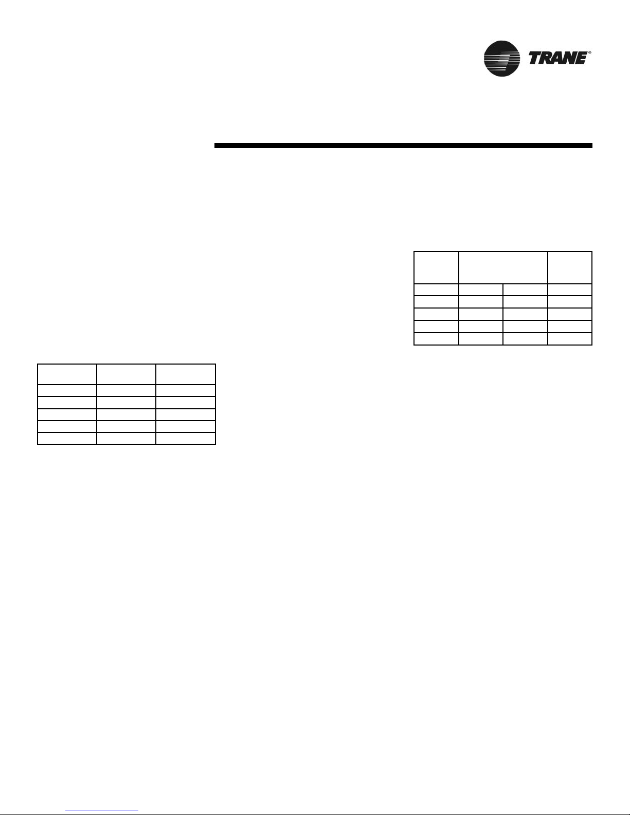
floor. See Figures 6-10 for unit
dimensions and Table 5 for unit
weights.
2. Wall space design should allow
the unit to be mounted to the
wall securely. The wall surface
behind the unit should be
smooth and level. A wall slightly
out of level may cause problems
with unconditioned air
leaking into the room. Remove
any object projecting more then
1/8” (.3175cm) from the wall surface.
NOTE: Additional gasketing
may be installed to accommodate for uneven wall.
3. There are two removable knockouts in the rear of the unit, on
either end, for piping and
electrical supply lines. A pipe
chase is located in the upper
back portion of the unit for
crossover piping
(See Figures 6-
10)
. The Fresh Air opening is
located in the lower back of the
unit and the path to the wallbox
on the outside wall should be
unobstructed.
4. The physical layout of the room
should accommodate any accessories ordered with the unit.
Conditioned air is distributed
through the grille on top of the
unit and returned through the
return air grille on the bottom of
the unit. Avoid placing any
objects that may obstruct either
grille or interfere with airflow.
5. Internal access to the unit is
provided by the removable front
panel. Sufficient space should be
allowed to lift the panel for
maintenance purposes.
6. Make sure the unit is placed on a
level surface. The unit leveling
legs can also be adjusted to
accommodate slight out-of-level
installation surfaces.
Horizontal Unit Ventilators
7. Ceiling hung design must be of
sufficient structure to support the
weight of the unit.
See Table 5 for
weight data.
Figures 11-14 show
hanging rod location and placement.
NOTE: Isolator and suspension
rods are to be provided by the
installer. Trane recommends 3/8”
rods for hanging suspension.
8. Service access is gained through
the access panels on the bottom of
the unit. Sufficient space should
be allowed for panel removal. If
the hinged panel option is
ordered, allow for a swing radius
of 14”.
Vertical and Horizontal Units
9. Sufficient free area around both
the discharge and wall box
should be maintained to ensure
proper ventilation. If any part of
the discharge is blocked off, unit
performance may be effected. If
the wall box is too small on the
inlet, water or debris could be
pulled into the unit.
See Table 6
for minimum wall box free area
requirements.
10. Use the shortest and most
efficient ductwork possible when
ducting the discharge and/or
return air grille. Units ordered
with a duct collar discharge
arrangement are equipped with a
1” duct flange.
NOTE: Ductwork
for ducted units will be provided
by the installer.
11. If installing a split system, refer
to the condenser installation
instructions provided with that
unit for special location considerations.
NOTE: Measurements in Figures
6-10 do not include adjusted
leveling legs. Adjustment of
Leveling legs should be done first.
New measurements from the
floor should be retaken before
installation.
Unit Size
Vertical Unit
lbs (kg)
Horizontal
Unit lbs (kg)
070 320 (145) 340 (154)
100 405 (184) 375 (170)
120 450 (204) 435 (197)
150 470 (213) 500 (227)
200 NA 600 (272)
Unit Size
Discharge sq. in.
Vert./Hor.
Inlet
sq. in.
Vert./Hor.
070 290 232 169
100 370 296 217
120 450 364 265
150 530 430 313
200 NA 576 391(Hor.)
Table 5: Typical unit weights*
* Weight at time of shipping. Subtract approx. 10%
for actual hanging weight.
Table 6: Wall box free area
requirements
Page 20
20 UV-SVN002-EN
Installation
Vertical Unit Ventilator
Subbase
A subbase may be used to increase the
unit height and aid in leveling the unit.
The subbase is shipped separately for
field installation. Slots and leveling
screws are provided on the subbase.
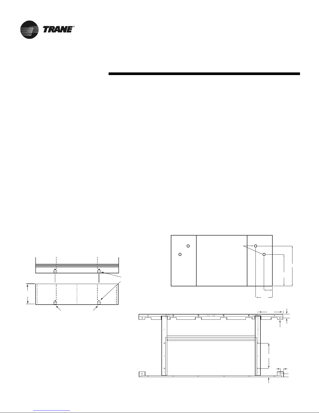
1. Remove the leveling legs provided
with the unit.
See Figure 16.
2. Set the unit on the subbase and
fasten with 4-3/8” x 16’ x 1-1/2”
hex head cap screws.
NOTE: Hex
screws provided by installer.
Predrilled slots in the subbase flange
will line up with the weld nuts in
the bottom of the unit.
3. The bottom of the subbase has weld
nuts in four slots. Place the leveling
legs in those slots and level the unit.
Unit Mounting
NOTE: All wall intake boxes should be
installed prior to mounting the unit
ventilator.
Refer to Page 49 for wall box
installation instructions.
Vertical Unit Ventilator
The 1/2” mounting or anchoring holes
are located on the back of the unit on
each end.
See Figures 17 and 18
.
NOTE: All mounting fastener are to be
provided by the installer.
1. Take care not to bend the front
return air grille while handling the
unit
2. Check the gasket on the rear of the
unit and around the fresh air opening. Gaps around the openings can
lead to outside air leaks into the
room.
3. Remove all electrical and piping
knockouts where required for
installation.
4. Set the unit in its selected location
and adjust leveling legs if necessary
to ensure level
fit.
See Figure 16.
Note: Unit must remain level. Coils
and drain pans inside the unit are
pitched properly for draining before
shipment.
5. Push the unit tightly against the wall
to compress the seal on the back
edge of the unit and intake opening.
Anchor the unit by using the 1/2”
mounting holes in both end pockets.
See Figures 17 & 18.
6. Make sure the unit rests tightly
against the wall. Check for proper
seal and that air does not leak
underneath the unit.
7. Replace all covers, panels and filters
before starting the unit.
Figure 16: Subbase installation with
leveling legs
Figure 17: Mounting holes for standard 15-1/4” &
16-1/4”depth unit ventilator
Figure 18: Mounting bracket with
1/2” mounting holes for
21-1/4” depth unit ventilator.
Mounting holes
1/2" diameter
End Pocket
Unit Base
2"- 6"
Subbase
For leveling legs
Weld
Nuts
Unit Back
11-1/2"
1"
12"
Mounting holes
1/2" diameter
12"
4"
16-1/4"
13-1/2"
1-3/4"
1-1/2"
1-5/8"
Page 21
UV-SVN002-EN 21
Installation
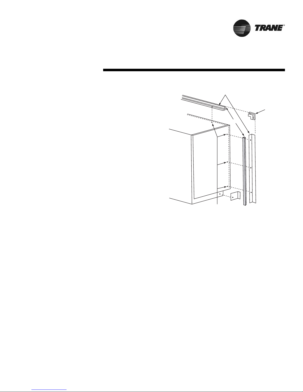
Recessed vertical units (Option)
The optional recessing flange assembly
includes pre-cut flanges, corner transition pieces, mounting screws, filler
pieces and pressure sensitive gaskets.
Refer to Figure 19 for a typical vertical
installation. To install the recessing
flange, complete the following procedures:
1. Make certain both end covers are
secured to the unit.
2. Measure and cut the pressure
sensitive gaskets to the correct
lengths and attach to the flanges.
3. Starting at a corner, attach the top
flange with the metal cutting screws
provided.
4. Press the corner transition pieces
onto the end of the flange and
attach the adjoining flanges and
filler pieces at the bottom of the
unit. Work around the unit in this
manner until all flanges and corners
are installed.
5. Mounting holes are pre-drilled in
the flanges. Use the assembled
flanges as a template to drill all
7/32’’ mounting holes in the cabinet.
6. Attach the flange section to the unit
cabinet with the mounting screws
provided.
7. Open and remove the front acces
panel.
8. Set the unit in place and push it
tightly against the back support and
flush with the wall surface. Anchor
the unit to back supports, using the
1/2’’ mounting holes described in
the Unit Mounting section.
9. Tighten the mounting fastener,
making sure that the unit is level.
NOTE: Unit must be mounted level.
Coils and drain pans inside the unit are
pitched properly for drainage before
shipment.
End Covers
When ordered as an option, end covers
ship already attached to the vertical
unit ventilator. The following section is
for installing end covers purchased as
an add-on.
It is recommended end panels be
installed on the unit ventilator after all
piping, wiring and accessory installation is completed.
To install the end panel:
1. Insert the four factory provided
metal studs into the four
pre-mounted nuts on the inside of
the panel.
2. Align each stud with the four predrilled holes on the side of the unit.
3. Secure the panel to the unit by
fastening with the four factory
provided nuts.
4. Do not over-tighten screws.
CAUTION
Equipment Damage
Do not run units for any length of time
without all panels and filters properly
installed. Failure to do so may result in
equipment failure.
Figure 19: Recess
flange installation
for vertical unit
ventilators
Vertical Unit
Back
Recessing
Flanges
Corner
Transition Piece
Gaskets
7/32" diameter holes
drilled for flange mounting
Page 22
22 UV-SVN002-EN
R
Installation
Horizontal Unit Ventilator
The horizontal unit ventilator may be
attached directly to the ceiling or suspended from the ceiling by hangers.
Hanger rods should be at least 3/8’’
diameter steel to support unit weight,
as given in Table 5.
WARNING
Heavy Objects!
Always lift unit with fork trucks or other
special lifting device following the recommended procedures. Failure to properly lift the unit as instructed, could
result in death or serious injury.
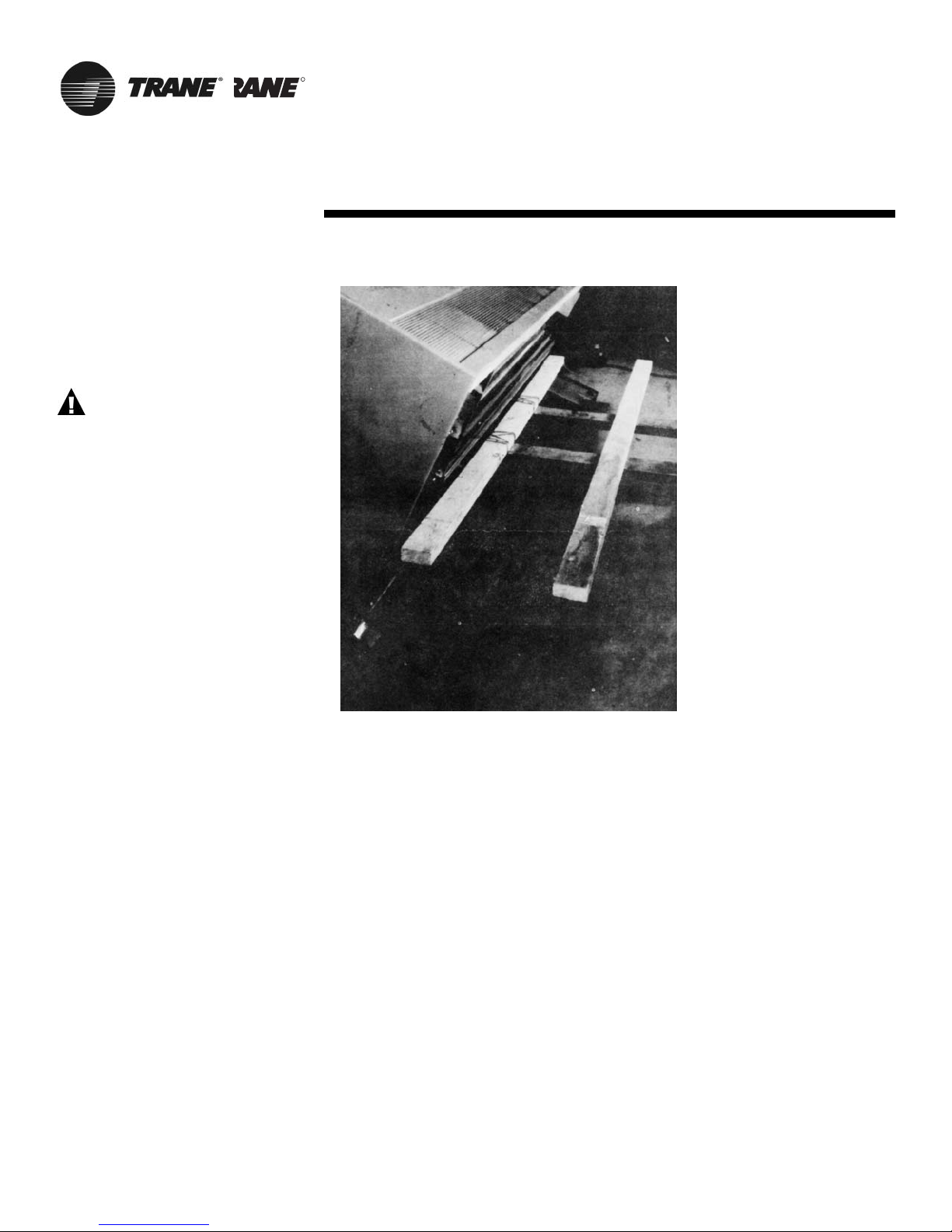
Install the hanging devices before hoisting the unit. A fork lift or other special
lifting device is required to hoist the
unit into mounting position.
Protect the unit finish by covering the
lifting platform.
To hoist the unit into place, follow the
instructions below:
1.Secure 2 x 4’s to the lift forks
as shown in Figure 19. These two
supports must be long enough and
spaced properly on the forks to
support the unit while it is being
lifted and clear the duct flanges on
the unit.
2. Tip the unit onto the supports and
slide it toward the lift until the
unit weight balances.
3. Lift the unit. Once in position,
temporarily secure the unit to the
hanger rods or mounting studs with
nuts and washers.
4. Align the unit with the duct work.
When in proper alignment, tighten
the mounting nuts securely.
5. Recheck the unit alignment and
make sure the unit is level.
6. Replace all covers, panels and
filters before starting the unit.
Figure 20: Preparing the horizontal classroom
ventilator for lifting and installation.
Page 23
Installation
Horizontal Recessed Mounting
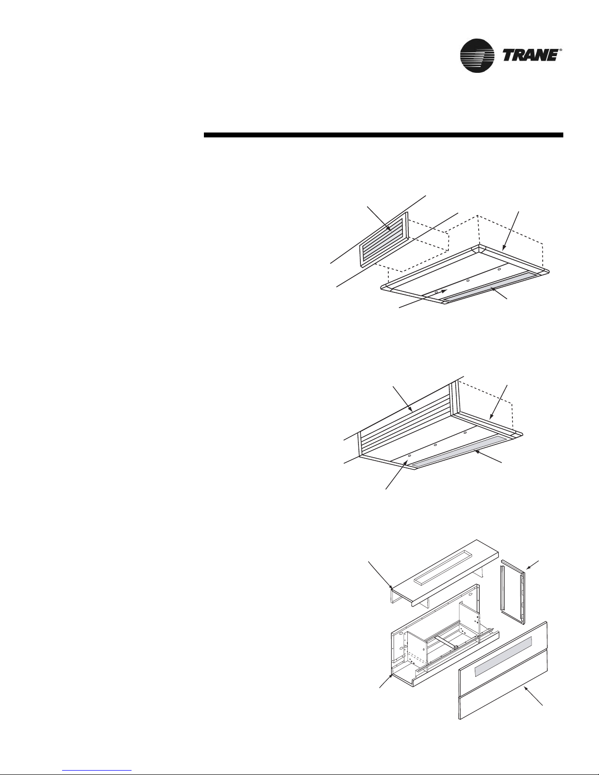
The recessing flange assembly includes pre-cut
flanges, corner transition pieces, mounting screws,
filler pieces and pressure sensitive gaskets. Refer
to Figures 21 & 22 for typical horizontal installation
1. Measure and cut the pressure sensitive gaskets
to the correct lengths and attach to the flanges.
2. Starting at a corner, attach the top flange with
the metal cutting screws provided.
3. Press the corner transition pieces onto the end
of the flange and attach the adjoining flanges
and filler pieces at the bottom of the unit. Work
around the unit in this manner until all flanges
and corners are installed.
4. Mounting holes are pre-drilled in the flanges.
Use the assembled flanges as a template to drill
all 7/32’’ mounting holes in the cabinet.
5. Attach the flange section to the unit cabinet
with the mounting screws provided.
6. Open and remove the front acces panel.
7. Tighten the mounting fastener, making sure
that the unit is level.
8. Open the unit access panel and remove the
bottom front panel.
See Figure 23.
9. Hoist the unit onto a forklift and mount in place
as described in the Unit Mounting section,
ensuring the unit is secured and aligned in
place, and that the mounting nuts are tightly
fastened.
NOTE: Unit must be mounted level. Coils and
drain pans inside the unit are pitched internally
for proper drainage.
10. Replace all covers, panels and filters
before starting the unit.
Figure 23: Horizontal unit ventilator with front panel
removed
UV-SVN002-EN 23
Supply Air
G
Figure 21: Recess flange installation around horizontal
unit ventilator access panel and inlet
Figure 22: Recess flange installation around bottom and
front of horizontal unit.
rille
Recessing Flange
Return Air
Access Panel
Inlet Grille
Supply Air
Grille
Access Panel
Recessing Flange
Return Air
Inlet Grille
Discharge Panel
End Cover
Intake Panel
Bottom Front Panel
Page 24
24 UV-SVN002-EN
Installation
Piping Installation
NOTE: Before installation of piping
package, the shipping bracket holding
the piping in place, must be removed.
Proper installation of piping is necessary to provide efficient coil operation
and to prevent damage during operation. Follow standard piping practices
and include all accessories as necessary.
Piping connection knockouts are shown
in Figures 6 through 14. Field connection types and sizes for units without
piping packages are listed in Table 7.
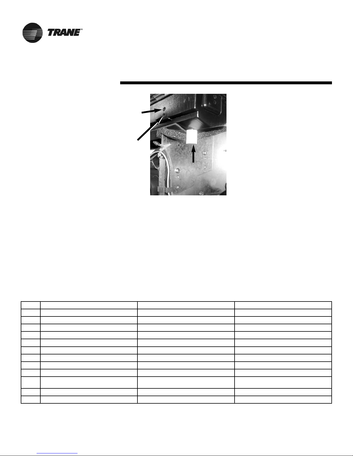
A 3/4’’ OD condensate drain connection
is provided on the chilled water supply
end of the unit. Figure 24 shows the
vertical unit connection. Attach a flexible condensate drain hose over the
drain pan connection and secure with a
hose clamp.
The drain pan on the vertical is vacuum
molded with a drain connection at each
end. The cooling side connection is cut
at the factory.
To field reverse the slope of a vertical
unit drain pan, plug the factory cut connection and cut the membrane of the
connection on the other side. Then
reverse the screws on each corner of
the drain pan.
Example:
To drain to the
right, put the right-hand drain screw in
the top hole and the left-hand screw in
the bottom hole.
(See Figure 24)
.
The drain pan on the horizontal unit is
internally pitched. To field reverse,
remove the screws and drain pan,
rotate the pan and reinstall.
After the condensate drain piping has
been completed, check water flow to be
sure the system properly carries and
away all condensate accumulation.
A P-trap is recommended for installations that drain directly into a sewer
system. A P-trap is not necessary for
operation but will eliminate sewer gas
odor.
Trane Piping Packages (Option)
Trane Standard Piping Package includes
a 2-way or 3-way valve with bypass balance valve, ball valves, Pete’s plugs and
unions. A strainer and circuit balancing
valve are optional.
All union connections should be tightened in the field. Units are shipped with
union connections hand tightened only
in the factory.
NOTE: All connections made in the
field should be sweat connections.
NOTE: Piping packages are not shipped
insulated. Any insulation should be
provided in the field by the installing
contractor.
Figure 24: Drain pan connection. Field
install a flexible hose for condensate
drainage.
Coil Description Connection Location Field Coil Connection
A 2-pipe chilled water/Hot water Left or Right 7/8” OD male sweat
H Hot water only Left or Right 7/8” OD male sweat
D 4-pipe chilled water/Hot water Left or Right (opposite ends) 7/8” or 5/8” OD male sweat
X Chilled water/Electric heat Left hand cooling/Right hand heat 7/8” OD male sweat
K1, 2 Steam Left or Right 1” MPT
DK Chilled water/Steam Left or Right 7/8” OD/ 1” MPT
R 2-pipe chilled water/Reheat hot water Left or Right 7/8” or 5/8” OD male sweat
E Electric heat only Right hand heat NA
F0 DX only Left hand cooling 7/8” suction, 3/8” discharge
FA DX/hot water Left hand cooling/Right hand heat
7/8” suction, 3/8” discharge/
5/8” OD Male sweat
FK DX/Steam Left hand cooling/Right hand heat 7/8” suction, 3/8” discharge/ 1” MPT
F3, 4, 6 DX/Electric heat Left hand cooling/Right hand heat 7/8” suction, 3/8” discharge/NA
Table 7: Coil Data
Notes:
1. Supply and return connections are located on the same end of each coil.
2. All Trane piping packages have union connections; all units with piping packages by others have sweat connections.
3. Coil connections are sweat except steam coils, which are threaded
Condensate
hose connection
Screw
here for
left side
drain
Screw
here for
right side
drain
Page 25
UV-SVN002-EN 25
Installation
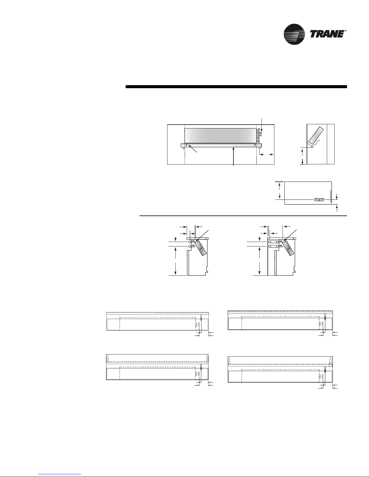
Figure 25: Condensate drain pan
dimensions and screw location.
7/8 I.D.
Standard & 1” falseback
6” falseback
Installation Crossover Piping
Crossover piping is available for A, D
and H coils. It is either 1 3/8’’ \[34.9\] or
2 1/8’’ \[54\] in diameter (O.D.) as specified by the customer. Crossover piping
can be found in either the left or right
hand end pocket.
See Figure 26.
On D style coils, crossover piping connects to the main cooling coil.
Factory insulation is provided on all
crossovers.
When a Trane piping package is
ordered, it is installed with the connections made to the supply and return of
both the coil and the crossover piping.
However, supply and return connections must be made in the field when a
piping package is furnished by the
installer.
The crossover piping is located at the
back of the unit along the wall and the
ends of the piping are flush with the
end of the unit.
Expansion compensation
between the piping package
and the crossover piping is
achieved using flex hoses
rated at 250 psi working
pressure. Expansion compensation for the crossover
piping must be handled
external to the unit ventilator.
Figure 26:
Typical crossover
piping
Screw
Location
6-1/4"
2-1/4"
3-5/8"
23"
15 1/4" & 16 1/4" DEPTH UNIT
TOP VIEW
7 1/2"
9 1/2"
21 1/4" DEPTH UNIT
Cooling Supply End
Coil
Condensate Drain Pan
Field Connection
w/Ball Shutoff
11-1/4"
3-5/8"
1-/14"
23"
Vertical Unit
11 "
Horizontal Unit
13-5/8"
16 1/4" DEPTH UNIT
TOP VIEW
21 1/4" DEPTH UNIT
13-1/4"
Field Connection
w/Ball Shutoff
7 1/2"
9 1/2"
3"
TOP VIEW
7 1/2"
9 1/2"
CROSSOVER PIPING IS AVAILABLE FOR A, H AND D COILS. FOR ALL D (4-PIPE) COILS, TRANE
PROVIDES THE CROSSOVER FOR THE COLD WATER ONLY. THE CROSSOVER PIPE IS FACTORY INSULATED
WITH 3/8"-THICK INSULATION.
EXPANSION COMPENSATION BETWEEN THE FACTORY PIPING PACKAGE AND THE CROSSOVER
PIPING IS ACHIEVED USING A FLEX HOSE RATED AT 250 PSI WORKING PRESSURE. FLEX HOSE
IS ONLY AVAILABLE WITH FACTORY MOUNTED PIPING PACKAGES.
EXPANSION COMPENSATION FOR THE CROSSOVER PIPING MUST BE HANDLED EXTERNAL TO
THE UNIT VENTILATOR.
CROSSOVER CONNECTIONS TERMINATE IN THE SAME END POCKET AS THE MAIN COIL CONNECTION.
THE MAIN COIL CONNECTION FOR 2-PIPE SYSTEMS IS THE HEATING COIL. THE MAIN COIL CONNECTION
TOP VIEW
7 1/2"
9 1/2"
Page 26
26 UV-SVN002-EN
Installation
Split System Units
The following refrigerant piping and
interconnecting wiring instructions
apply to unit ventilators with direct
expansion type cooling coils used in
conjunction with air-cooled condensing
units. Reference must also be made to
the condensing unit installation and
wiring manuals which are shipped with
the condensing unit.
NOTE: A UL listing mark applied to a
unit ventilator does not apply to any
associated refrigerant condensing unit
.
Refrigerant Piping
Unit ventilators with direct expansion
cooling contain a nitrogen holding
charge in the evaporator coils.
Connections are ‘‘pinched off’’ at the
factory.
To connect the condensing unit lines,
cut off the stubouts and swage. The
condensing unit lines can then be
brought into the swage and brazed.
Trane recommends the use of nitrogen
purge when brazing refrigerant lines to
prevent formation of oxides in the
lines.
Install the refrigerant suction and liquid
lines as described in the condensing
unit installation instructions. The TXV is
factory installed on the Unit Ventilator.
Piping should be run straight out
through the back of the unit. Access
piping knockouts are located in the rear
panels of the unit, as shown in Figures
6 through 14.
Recommended refrigerant line connections for various unit combinations are
given in Table 10. Typical Superheat
Charging Charts are shown in the Trane
Service Facts found in the condensing
unit section manual. Refrigerant charge
weights can also be determined with
your local Trane sales engineer using a
valid Trane Selection Program.
Unit
Size
Condensing Unit UV Connection Size
Condensing Unit
Connection Size
Liquid Line Size Suction Line Size
075 TTB, TTP
Liquid - 3/8”
Suction - 7/8”
Liquid - 3/8”
Suction - 7/8”
3/8” OD 7/8” OD
100 TTP, TTB, TTA, 2TTA
Liquid - 3/8”
Suction - 7/8”
Liquid - 3/8”
Suction - 7/8”
3/8” OD 7/8” OD
125 TTB, TTA, 2TTA
Liquid - 3/8”
Suction - 7/8”
Liquid - 3/8”
Suction - 7/8”
3/8” OD 7/8” OD
150 2TTA, TTB, TTA
Liquid - 3/8”
Suction - 7/8”
Liquid - 3/8”
Suction - 7/8”
3/8” OD 7/8” OD
200 TTA, 2TTA
Liquid - 3/8”
Suction - 7/8”
Liquid - 3/8”
Suction - 7/8”
3/8” OD 7/8” OD
Table 10: Refrigerant Line Sizes (TTB, TTA, 2TTA & TTP Condensing Units)
Notes:
1. Refrigerant connections sweat and “pinched-off” at the factory
2. All DX Unit Ventilators are shipped with a Nitrogen holding charge.
Page 27
UV-SVN002-EN 27
Installation
Steam Piping
When air, water or another product is
heated, the temperature or heat transfer rate can be regulated by a modulating steam pressure control valve. Since
pressure and temperature do not vary
at the same rate as load, the steam
trap capacity, which is determined by
the pressure differential between the
trap inlet and outlet, may be adequate
at full load, but not some lesser load.
There are detailed methods for determining condensate load under various
operating conditions. However, in most
cases this is not necessary if the coils
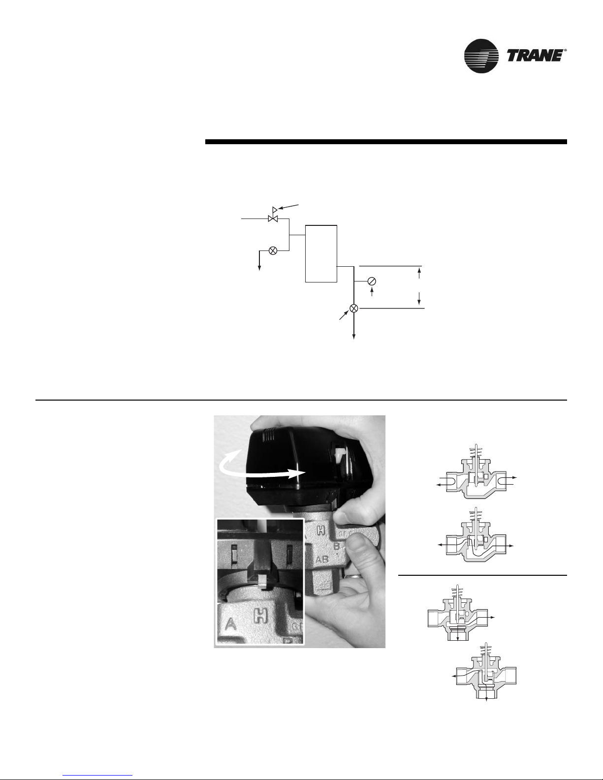
are piped as shown in Figure 27.
Follow the procedure documented in
the ASHRAE Systems Handbook,
Steam Systems.
Figure 27: Steam Piping
Modulating Water Valves
(Option) The actuator on the valve is a
24V, 3-point floating valve. The actuator
can be easily removed from the valve
body by pressing in on the locking tab
and rotating the actuator 45
O
counterclockwise (See Figure 28a). The 2-way
valves are bi-directional flow. The 3way valves can be mixing or diverting
(See Figure 28b).
NOTE:The actuator must be removed
if soldering is being conducted near
the valve. High heat may cause damage to the actuator’s plastic
body/mechanisms.
On applications without factory
installed piping packages (Option), it is
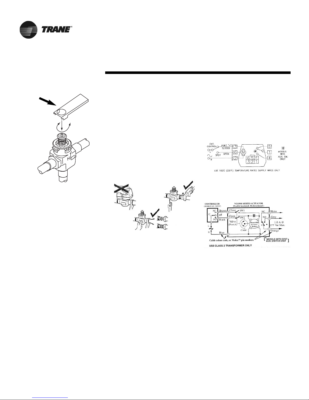
important to remove the cartridge
assembly from the valve body with the
provided tool (Figure 29).
Figure 28b: Steam Piping
Figure 28a: Remove modulating valve
actuator by pressing in tab (inset) and
turning actuator 45Ocounterclockwise.
Two-way
valve
Three-way
valve
Temp. Regulating Valve
Coil
To Condensate
return
Vacuum Equalizer
F&T Trap
See text for sizing
Gravity flow to
vented receiver
H= 12"
minimum
A
A
AB
A
Closed
Open
AB<->B
B
B
B
AB<->A
AB
Page 28
28 UV-SVN002-EN
Installation
Use the following steps to complete
cartridge assembly removal:
1. Remove valve actuator.
2. Remove the cartridge assembly
from the valve body with the
enclosed tool.
3. Solder the valve in accordance with
normal soldering practices.
4. Re-install the cartridge after
soldering by tightening until it
bottoms out. The top surface of the
cartridge will be flush with the top
edge of the body casting.
NOTE: Do
not over-tighten. Maximum torque
is 40 in-lb
.
5. Replace valve actuator and wire in
accordance with instructions.
Plumbing
The valve may be plumbed in any
angle but preferably not with the actuator below horizontal level of the body.
Make sure there is enough room
around the actuator for servicing or
replacement.
For use in diverting applications, the
valve is installed with the flow water
entering through the bottom AB port
and diverting through end ports A or B.
In mixing applications the valve is
installed with inlet to A or B and outlet
through AB.
Mount directly to the tube or pipe. Do
not grip the actuator while making or
tightening plumbing connections.
Either hold valve body by hand or
attach an adjustable spanner (38mm/11/2”) across the hexagonal or flat faces
on the valve body (See Figure 30).
Manual Opener
The manual opener can be manipulated
only when in the up position. The A port
can be manually opened by firmly
pushing the white manual lever down
to the midway position and pushing the
lever in. In this position, both A and B
ports are open. This “manual open”
position may be used for filling, venting
and draining the system or opening the
valve during power failure.
The valve can be closed by depressing
the white lever lightly and then pulling
the lever outward. The valve and actuator will return to the automatic position
when power is restored.
NOTE: If the
valve is powered open, it cannot be
manually closed, unless the actuator is
removed.
Wiring
A controller and a separate transformer
is required to operate each valve (See
Figures 31 & 32). Port A “open” and
“closed” denote valve open and closed
positions.
The typical floating controller is an
SPDT controller with a center-off position. On a change in temperature from
the set point, the controller will close
the NO or NC contacts, driving the
valve to an intermediate position until a
further change at the controller.
The valve is set between the limits of
the controller to satisfy various load
requirements. In the event of power
failure, the valve will stay in the position it was in before loss of power.
When power is restored, the valve will
again respond to controller demand.
Figure 29: Cartridge removal tool
Figure 30: Proper plumbing technique
for modulating valves.
Figure 31: Wiring for modulating valve
actuator
Figure 32: Wiring for modulating valve
actuator
Page 29
UV-SVN002-EN 29
Installation
Isolation Valves
Installation
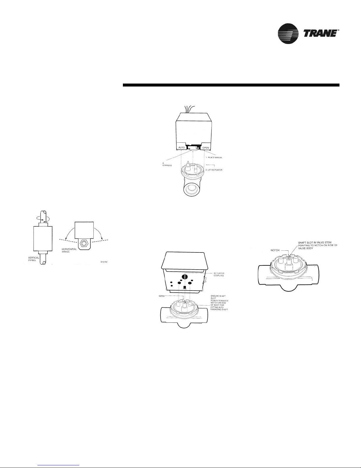
The valve can be mounted in any position on a vertical line. If the valve is
mounted horizontally, the actuator must
be even with or above the center line.
Make sure there is enough room to
remove actuator cover for servicing.
Mount the valve on the tube or pipe.
NOTE: Make sure the flow through the
valve is in the direction indicated by the
arrow stamped on the valve body.
Servicing/Removal of valves
The actuator can be removed from the
valve body. Removing the actuator is
recommended of soldering is being
conducted near the valve. To remove
the actuator:
1. Place the manual operating lever to
the Open position (See Figure 34)
2. Depress the locking button and lift
actuator until it separates from the
valve body.
To install the actuator to the valve
body:
1. Align the slot on the shaft of the
valve with the valve body notch on
side of body (See Figure 35)
2. Install body valve into pipe.
3. Wiring connections may be made
either before or after actuator
in stalled on body.
4. Place the manual operating lever
on the actuator in the OPEN position.
5. Align actuator coupling to slot on
the shaft of the valve body and fit the
head onto the valve body to ensure
the shaft seats correctly (Figure 35).
6. Press the actuator and valve body
until it secures together.
Soldering procedures are as follows:
1. Remove actuator as stated earlier
2. Place valves on the pipe. Rotate
valve stem so the shaft slot points at
the notch in the side of the body (90
O
to flow direction). This protects the
plug inside the valve by removing it
from the seat. (See Figure 36)
3. Sweat the joints, keeping outer sur
face free from solder.
NOTE: Do not
use silver solder due to high
temperature requirements.
Figure 34:
Removing
isolation
valve
actuator
Figure 35:
Installing
isolation
valve
actuator
Figure 36: Preparation for soldering
Figure 33: Proper mounting for
isolation valves
Page 30
30 UV-SVN002-EN
Installation
Heating Coils with Direct
Expansion Cooling
Heating options for direct expansion
cooling in the unit ventilator are hot
water, steam or electric heat.
These coils facilitate direct expansion
cooling with standard capacities. The
supply and return connections are
located in the right hand end pocket.
Hot water field connections are made
with a 5/8’’ \[15.9\] OD male sweated
joint, while steam coils have a 1’’
\[25.4\] male pipe thread (MPT) connection (Table 5).
Electric heat coils provide a third way
to supply heating to the direct expansion cooling. The coil utilizes three to
six preheat elements which are factory
wired.
Wiring
WARNING
Hazardous Voltage!
Disconnect all electric power, including
remote disconnects before servicing.
Follow proper lockout/tagout procedures to ensure the power can not be
inadvertently energized. Failure to disconnect power before servicing could
result in death or serious injury.
A typical unit ventilator with DX coil
includes an outside air thermostat, a
frost prevention thermostat and a 24V
transformer for condensing unit control.
Wire sizing is the same as given for the
thermostat wiring in the condensing
unit installation instructions, or may be
obtained from the nameplate. The condensing unit must be controlled by the
same room thermostat that also controls the Unit Ventilator.
Split System Start-Up
After all piping and wiring has been
completed, follow the instructions provided with the condensing unit for control testing and system start-up. If
sweat type field-piped systems are
being used, then pressure testing, evacuation and refrigerant charging will be
required.
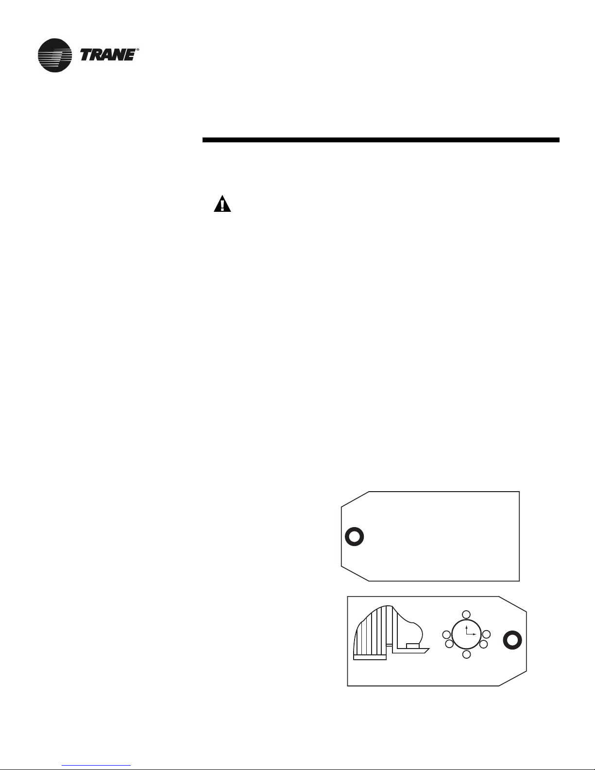
Two bulbs will also be shipped with a
split system unit:
1. Frost stat bulb
2. TXV valve.
Both components are to be field
installed using the installation kit
shipped with the unit. For complete
installation instructions and locations,
refer to the tag attached to the installation kit within the unit. See Figure 37
for an example of the installation tag.
NOTE: Depending on the controls package ordered with the unit, not all installations will require mounting the frost
stat bulb.
Figure 37: Frost stat/TXV valve installation tag
IMPORTANT:
INSTALLER MUST MOUNT THERMAL
EXPANSION VALVE BULB AND FROST
PROTECTION BULB (if suppled) TO
SUCTION LINE AFTER CONNECTION
OF FIELD REFRIGERANT PIPING
X39001939010A
X
12
93:00
X
3
6
4:00
9:00
8:00
MOUNT BULB IN
HORIZONTAL PLANE
RECOMMENDED
BULB PLACEMENT
Page 31
UV-SVN002-EN 31
Installation
Wiring
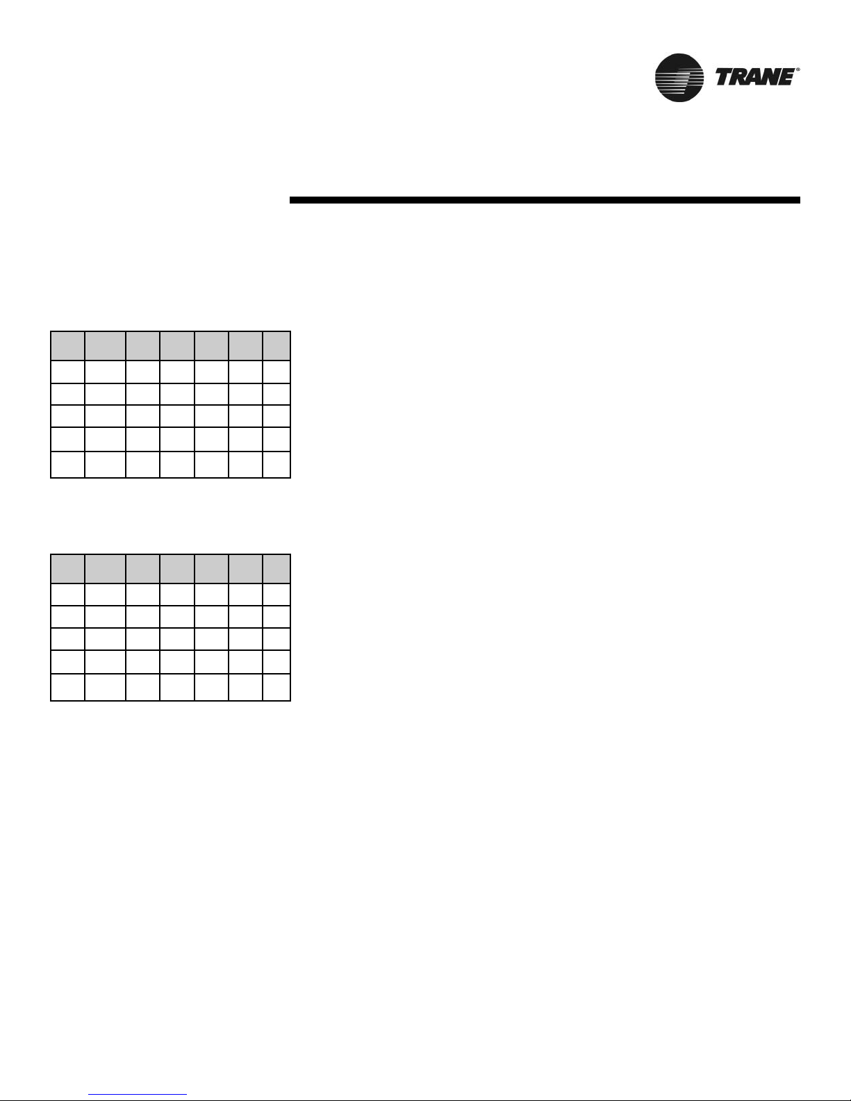
All classroom unit ventilators have 115V
motor power. Motor data can be found
in Tables 9 and 10:
Control Power
CAUTION
Control Power Wiring
Wiring diagrams given in this manual
are typical. Actual wiring for particular
units may differ. To prevent damage to
the unit, refer to the diagram provided
on the unit for specific wiring information.
Unit ventilator controls and control
wiring can be factory mounted or field
installed.
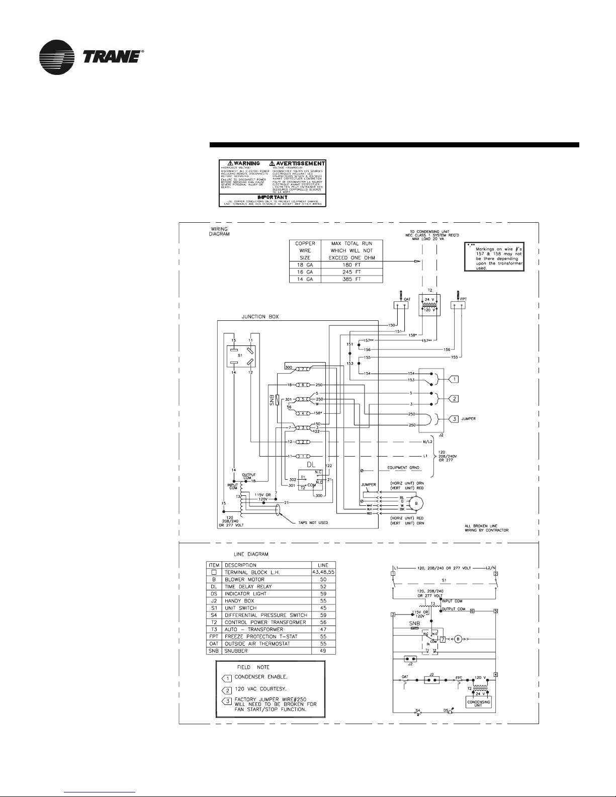
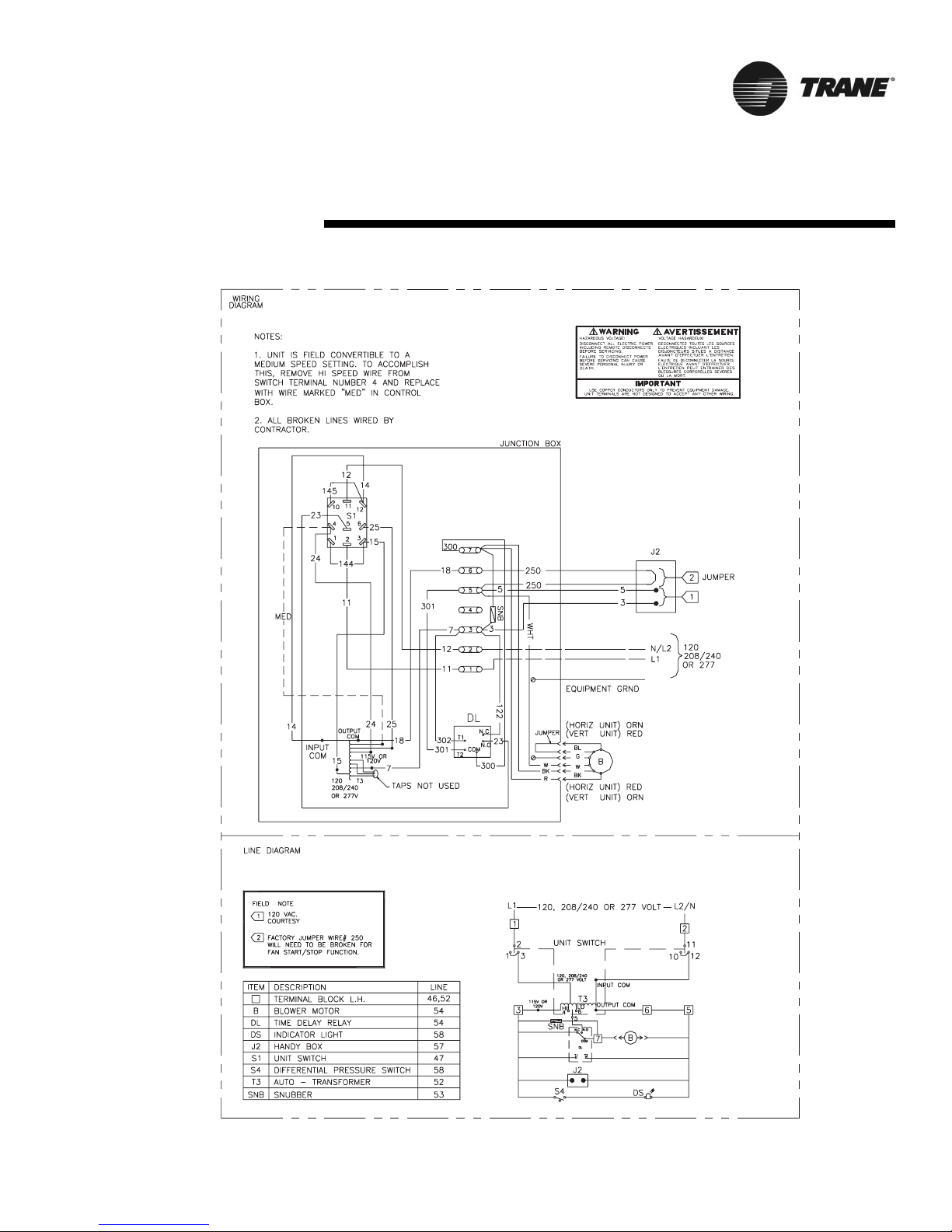
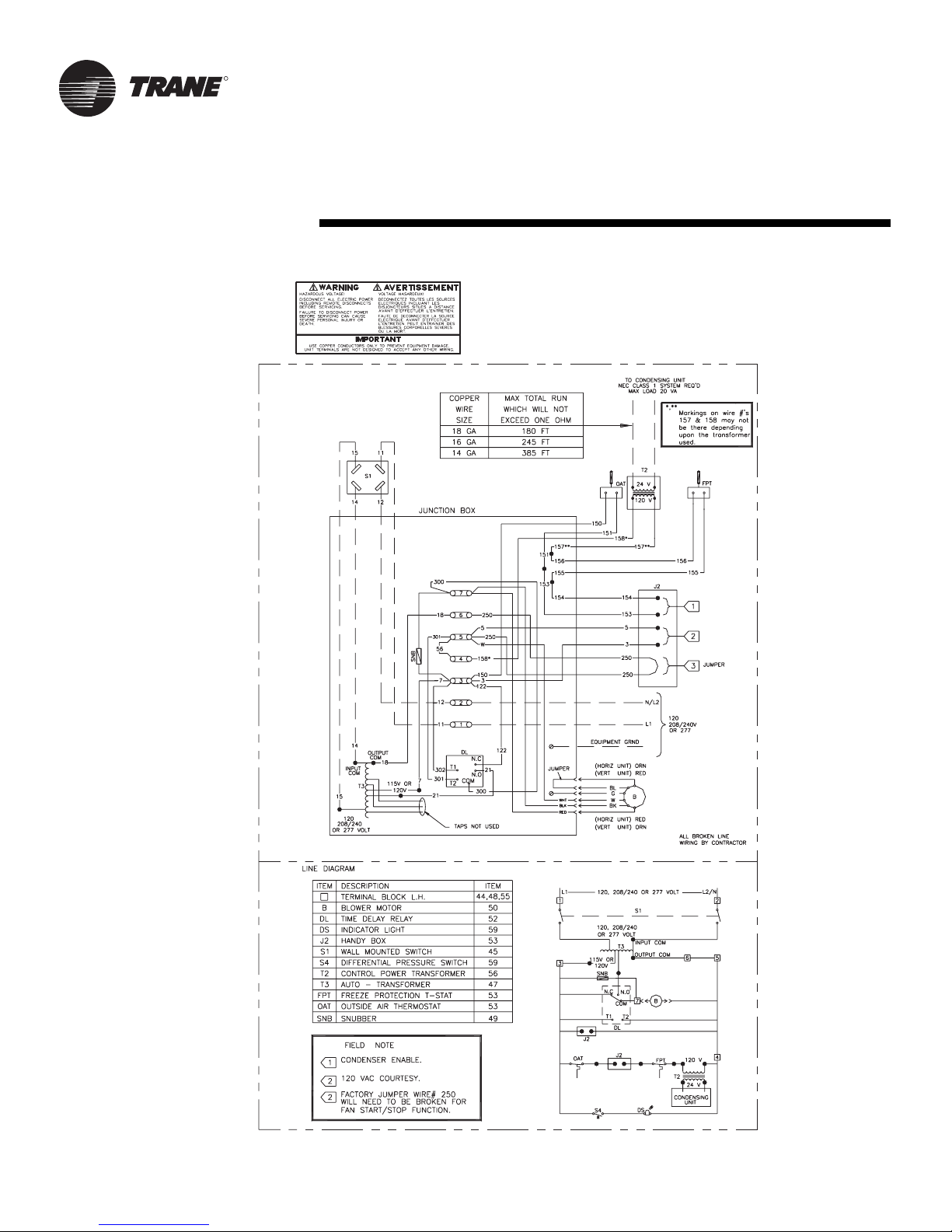
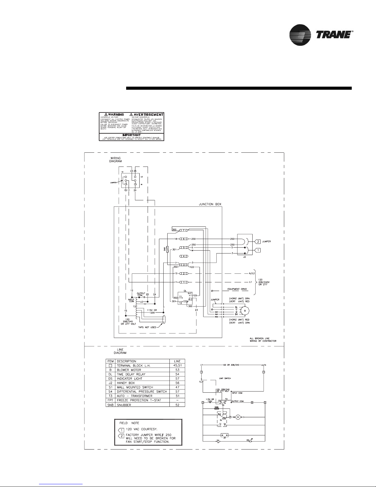
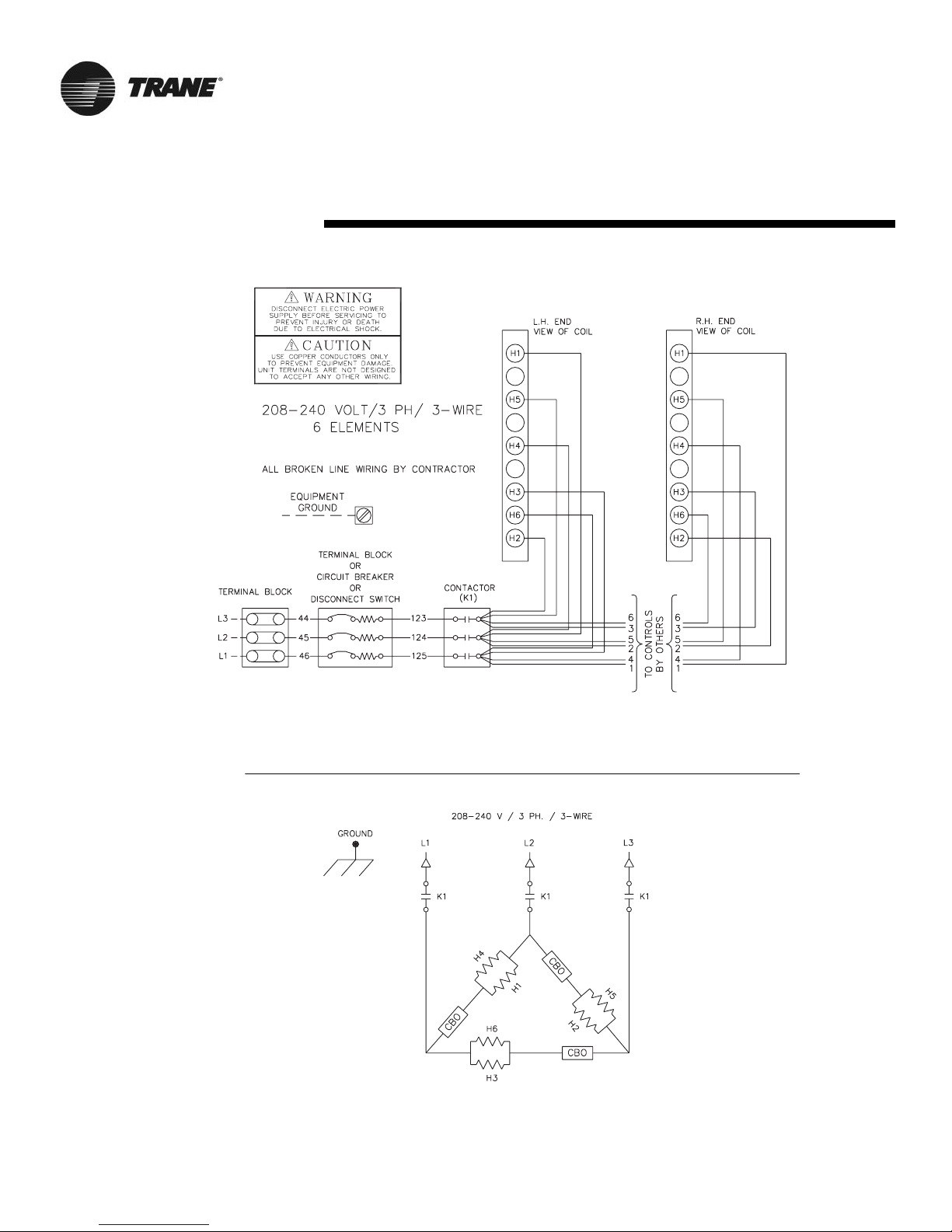
Wiring diagrams (Figures 38 and 41)
illustrate the standard unit motors with
one and two speed control. Terminal
wiring is provided by Trane and the
actual components used for a particular
installation may differ. Control and line
diagrams for the exact control system
used are provided with each unit.
CAUTION: When installing field provided controls, do not alter or remove any
built-in unit safeties. Tampering with
unit safeties may cause unit overheating and possible fire hazard.
CAUTION: Do not remove or alter the
wiring of the Time Delay Relay (DL).
Doing so may result in premature
motor failures.
Supply Power
CAUTION
Use Copper Conductors Only!
Unit terminals are not designed to
accept other types of conductors.
Failure to use copper conductors may
result in equipment damage.
Power supply wiring is to be connected
to terminals 1 and 2 at the junction box
in the left end pocket, below the discharge air grille.
Electric Heat
Supply Power
Supply power wiring is to be connected
to the following line terminals in the
right hand end pocket:
1. 208V or 240V, 3-phase, 3 wire system:
L1, L2 and L3. (See Figure 42)
2. 480V, 3-phase, 4 wire system:
L1, L2, L3 and N (neutral)
See Figure 43.
3. See Figure 44 for a typical unit line
and interconnecting wiring diagram
for Electric Heat Coils.
NOTE: 480 V/3-Wire is NOT compatible with Trane Classroom Unit
Ventilator equipment. There must be
a 4-Wire system with a separate
ground.
NOTE: The supply neutral wire must
be connected to the neutral terminal
block.
Operational controls and electric heating safety devices are factory mounted.
These devices are: high temp cut outs
and panel interlock, both of which deenergizer electric heating elements
through the K1 safety contactor.
Unit
Size
Volts RPM CFM Amps Watts HP
075 115/60/1 1075 750 2.3 222 1/6
100 115/60/1 1075 1000 2.3 222 1/6
125 115/60/1 1075 1250 2.6 287 1/4
150 115/60/1 1075 1500 2.6 287 1/4
200 115/60/1 940 2000 5.7 639 1/3
Unit
Size
Volts RPM CFM Amps Watts HP
075 115/60/1 1360 750 4.8 597 1/3
100 115/60/1 1360 1000 4.8 597 1/3
125 115/60/1 1410 1250 7. 0 844 1/2
150 115/60/1 1410 1500 7. 0 844 1/2
200 115/60/1 11 4 0 2000 8.1 936 3/4
Table 9: UV Standard Motor Data*
Table 10: Hi-ESP Motor Data*
* Data typical for AA Coil
* Data typical for AA Coil
Page 32
32 UV-SVN002-EN
Wiring Diagrams
Figure 38: Field Installed
Controls, 120V, 1 Speed Unit
Mounted Fan Switch
Page 33
UV-SVN002-EN 33
Wiring Diagrams
Figure 39: Field Installed Controls, 120V, 2 Speed Unit Mounted Fan Switch
Page 34
34 UV-SVN002-EN
Wiring Diagram
R
Figure 40: Field Installed Controls, Horizontal UV, 120V, 1 Speed Wall Mounted Fan Switch
Page 35
UV-SVN002-EN 35
Wiring Diagram
Figure 41: Field Installed Controls, Horizontal UV, 120V, 2 Speed Wall Mounted Fan Switch
Page 36
36 UV-SVN002-EN
Wiring Diagrams
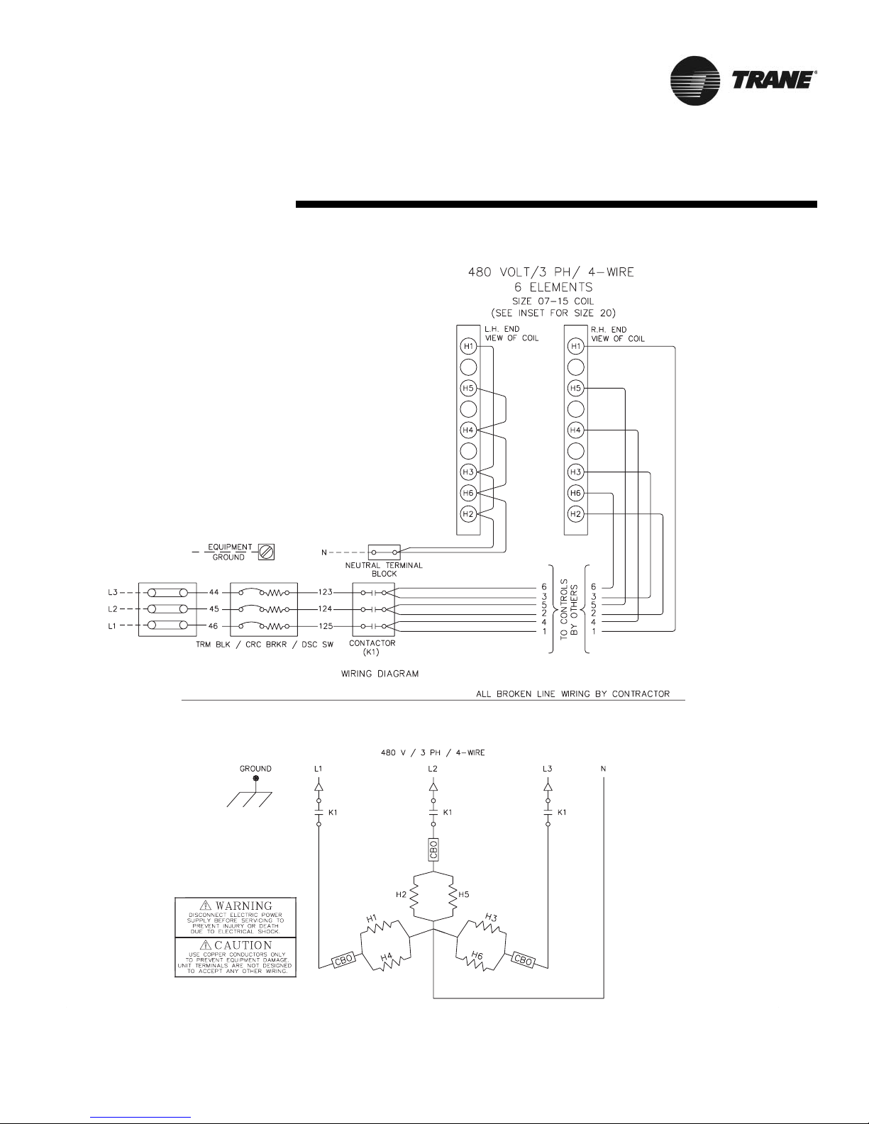
Figure 42: Power Diagram For 208V or 240V. 3-Phase, 3 Wire Electric Heat
Page 37
UV-SVN002-EN 37
Wiring Diagram
Figure 43: Power Diagram For 480V. 3-Phase, 4-Wire Electric Heat
NOTE: Important! Incoming
power to the unit ventilator
is 3-phase, 4-wire for a 480volt system. The system
contains 5 conductors: 3hot, 1-neutral and 1-equipment ground. The neutral
line can not be used as the
equipment ground.
Page 38
38 UV-SVN002-EN
Wiring Diagrams
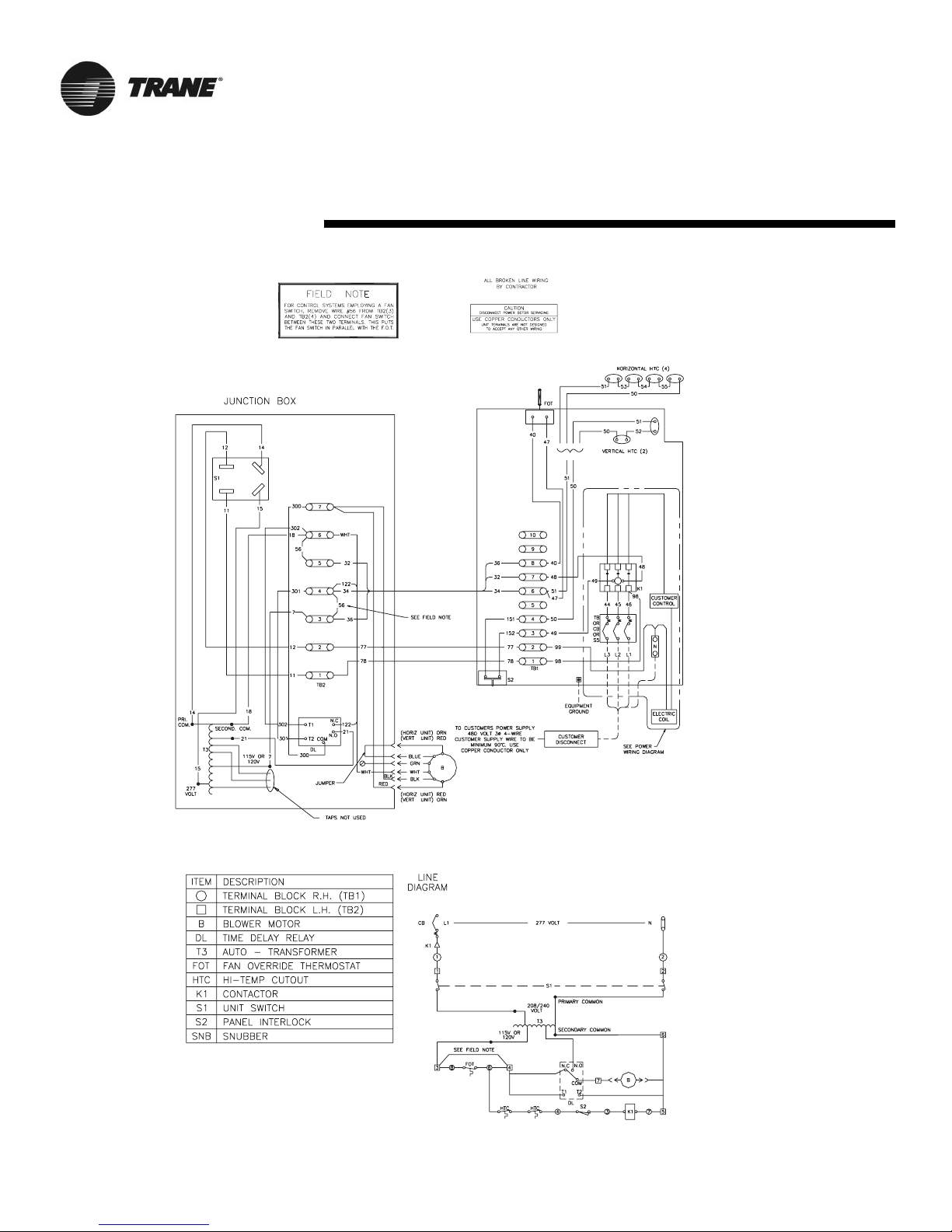
Figure 44: Power Diagram For 480V. 3-Phase, 4-Wire Electric Heat
Page 39
UV-SVN002-EN 39
Wiring Diagrams
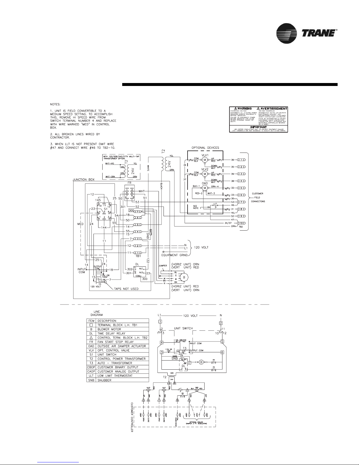
Figure 45: End Device Package 120V, 4 Pipe Hot Water - Chilled Water
Page 40
40 UV-SVN002-EN
Wiring Diagrams
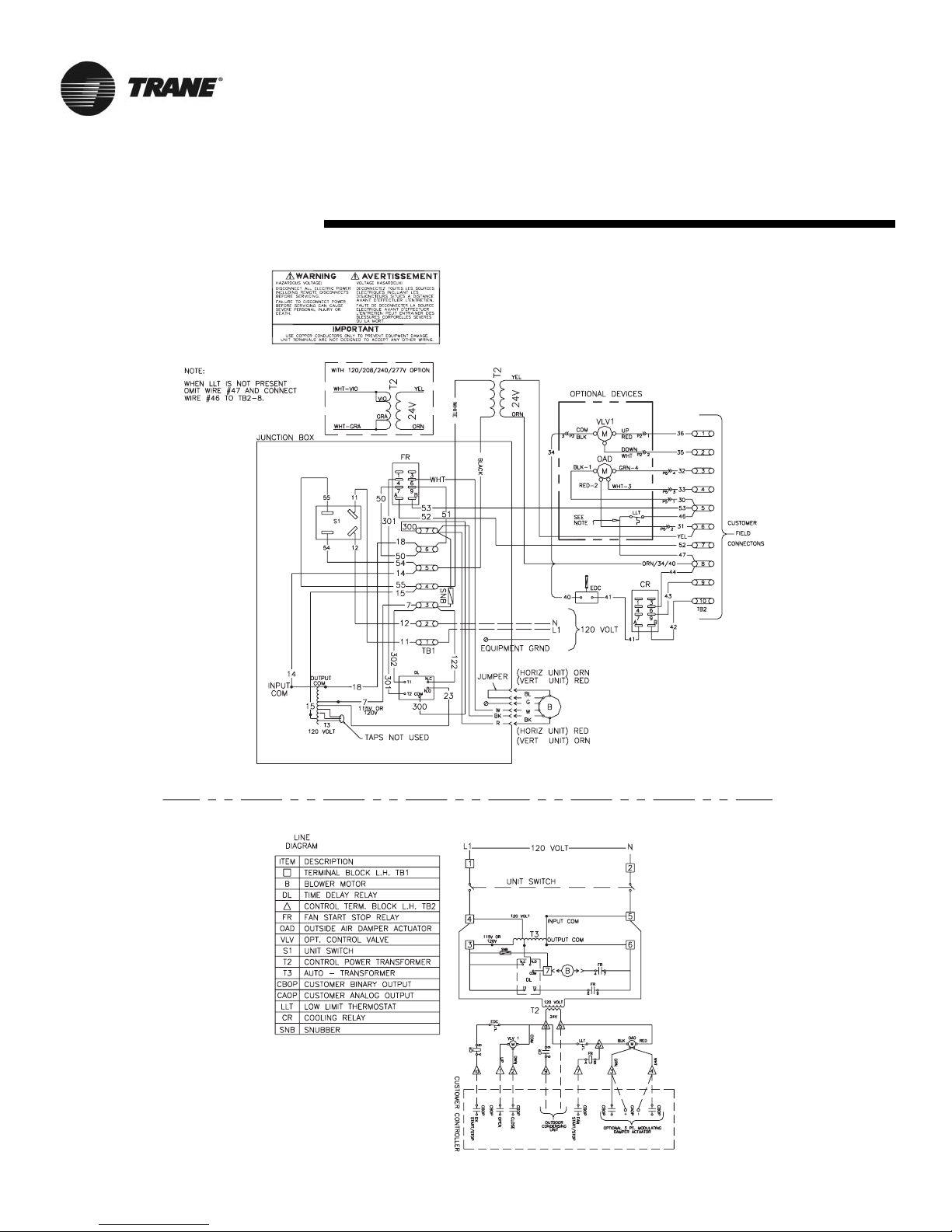
Figure 46: End Device Package 120V, Hot Water - DX Cooling
Page 41
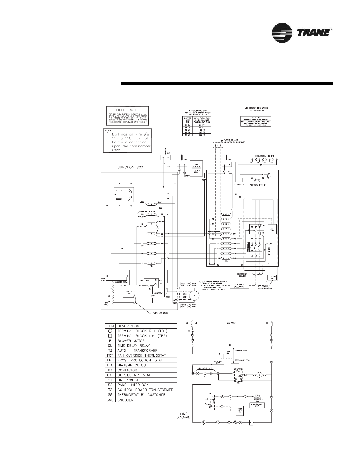
UV-SVN002-EN 41
Wiring Diagrams
Figure 47: 208V or 240V. 3-Phase, 3 Wire Electric Heat - DX Cooling
Page 42
42 UV-SVN002-EN
Electrical Data
Minimum Circuit
Capacity
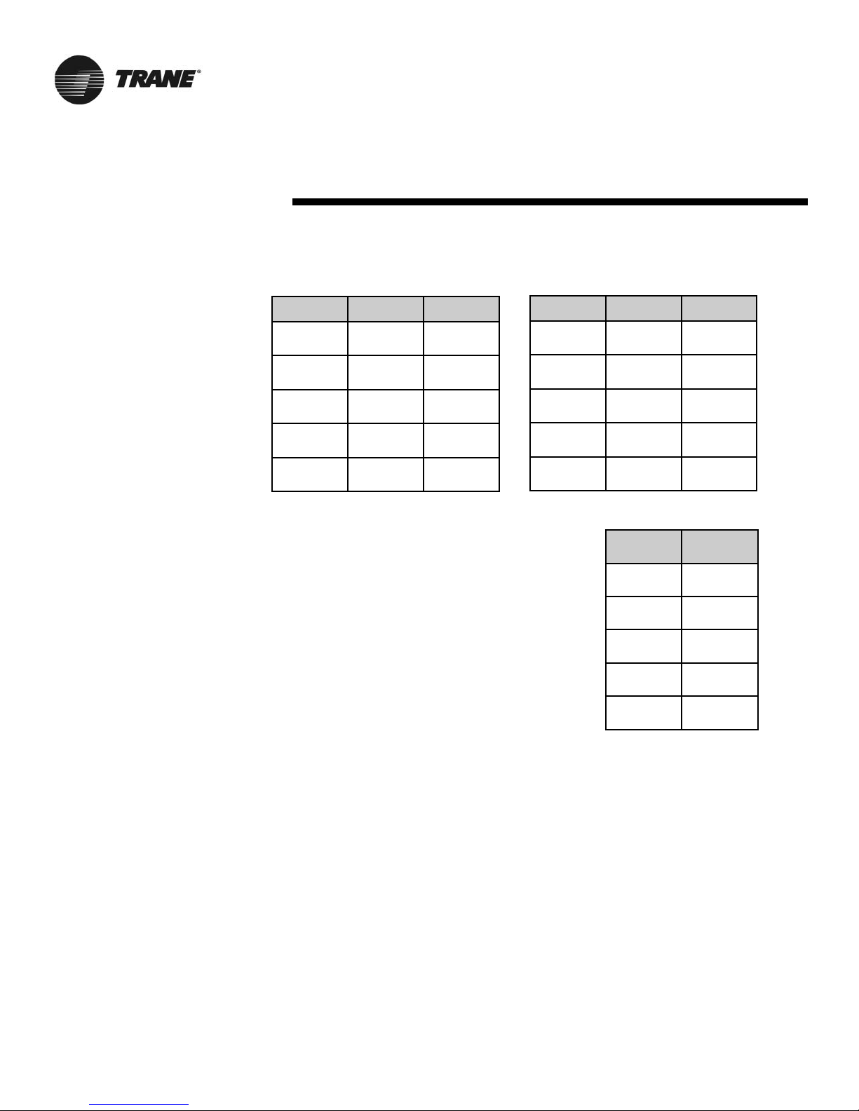
Table 11 describes the typical
MCA levels of a standard unit
ventilator with the necessary
voltage and amp add-ons for
unit mounted controls.
Unit Size HP Amps
075 1/6 (.17) 2.5
100 1/6 (.17) 2.5
125 1/4 (.25) 2.7
150 1/4 (.25) 2.7
200 1/3 (.75) 5.7
Unit Size HP Amps
075 1/3 (.33) 4.8
100 1/3 (.33) 4.8
125 1/2 (.50) 7. 0
150 1/2 (.50) 7. 0
200 3/4 (.75) 8.1
Table 11: MCA levels for standard and hi-static motor unit ventilators
Standard UV
Hi-Static Motor UV
Volts Amps
120 0.94
208 0.55
240 0.48
277 0.41
480 0.41
For Trane
Controls, add
the following
values to
determine
TOTAL MCA
UV with Controls
Page 43
UV-SVN002-EN 43
Maintenance
WARNING
Hazardous Service Procedures!
The maintenance and troubleshooting
procedures recommended in this section of the manual could result in exposure to electrical, mechanical or other
potential safety hazards. Always refer to
the safety warnings provided throughout this manual concerning these procedures. When possible, disconnect all
electrical power including remote disconnects before servicing. Follow proper lockout/tagout procedures to ensure
the power can not be inadvertently
energized. When necessary to work
with live electrical components, have a
qualified licensed electrician or other
individual who has been trained in handling live electrical components perform these tasks. Failure to follow all of
the recommended safety warnings provided, could result in death or serious
injury.
Service Access
To access the unit for water balancing,
motor access or other start-up and
maintenance functions, use one of the
following methods:
1. Remove the entire front panel and
put a blockoff over the air chamber in
the front.
2. Remove the return air grille by
releasing the mounting screws.
3. If there is no shelving or other
obstructions, removing the end panel
may allow more access..
Periodic Maintenance
The following maintenance suggestions
apply to all types of unit ventilators,
chilled water, hot water, split systems
and electric. Additional information for
controls not supplied by The Trane
Company should be obtained from the
controls manufacturer.
Split system unit ventilators include a
condensing unit and the instructions
provided with the condensing unit will
apply to the entire refrigerant system.
Filters
The air filters supplied with Trane UV’s
are specially designed for high lint content. Depending upon room conditions,
these filters will normally need to be
replaced every 4 to 8 weeks. To assure
proper unit operation, inspect the filters
monthly and clean or replace as
required.
Overloaded filters will reduce unit air
handling capacity, which may result in
insufficient heating during the morning
warm-up period and loss of natural
cooling capacity during mild weather.
Filter Replacement
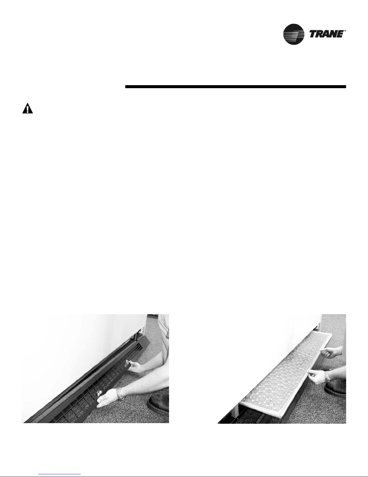
The air filter on the vertical unit is located near the bottom of the unit (Figures
48 & 49).
1. To remove the filter, begin by
unscrewing the four screws holding
the unit’s return air grille in place.
2. Remove air grille and slide the filter
out of the filter rack on the bottom of
the unit.
3. Replace old filter with new one and
re-attach return air grille
CAUTION
Equipment Damage
Do not operate unit without filters or
grille in place. Failure to do so may
cause equipment failure
For horizontal units, lower the back
access panel and lift the filter out of its
channel and out of the unit.
Figure 48: For filter replacement, remove the screws
holding the front air grille and remove the grille.
Figure 49: Slide out old filter and replace with new
filter. Reattach return air grille.
Page 44
44 UV-SVN002-EN
Maintenance
Filters - continued
There are a number of filters available
for use with the Trane Classroom Unit
Ventilators. The following section
explains maintenance and replacement
of these filters.
Each filter is replaced in the manner
previously discussed.
Throwaway Filters
Throwaway filters contain adhesive
coated glass fibers which are enclosed
in a cardboard frame. Remove old
filters from the unit and dispose of the
entire filter. Replace with a new filter
making sure the air flow direction
arrows are pointing toward the discharge end of the unit.
Permanent/Renewable
Polyurethane Filters
Permanent/renewable filters consist of
a polyurethane filter pad enclosed in a
rigid frame. The frame is hinged at the
back with dimple fastener at the front.
With the filter removed, open the
frame, remove the pad and wash in a
mild detergent solution. Allow the pad
to dry and replace in the frame.
Reinstall the filter. Over time, the filter
may wear out. Replacement pads may
be ordered through Trane.
Removal of the Drain Pan
The unit ventilators drain pan is removable for periodic cleaning or easy
access for maintenance/drainage
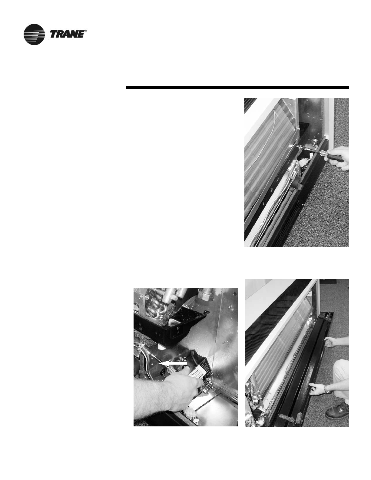
issues. Use the following Figures 50-
52, and the below steps for removing
the drain pan.
1. Turn off power to the unit and remove
the front panel by turning camlocks .
2. Disconnect the condensate drain line.
3. Remove the support plates on each
end by taking out the fastening
screws.
4. Remove the 2 screws on the front
face of the pan to release it.
NOTE: The drain pan is installed at
an angle to allow drainage. For each
end of the drain pan, remember the
position (top or bottom slot) from
which the fastener was removed.
5. When reinstalling, use the same
Figure 51: Removal of screws holding
drain pan in place.
Figure 50: Removal of screws in support plate of drain pan.
Figure 52: Slide drain pan out of unit
for inspection/cleaning.
Page 45
UV-SVN002-EN 45
Maintenance
steps in reverse order, remembering
the pitch of the drain pan.
Removal of the Fanboard &
Coil Cleaning
The unit ventilator fan board can be
removed for service to the blower
motor and fan wheels. The fan board
must also be removed for easier access
to the unit coils for cleaning and maintenance. Utilize the following steps for
proper removal of the fanboard.
1. Turn off power to the unit and remove
the front panel.
2. Remove the front air grille and filter
from the unit (As seen in Figures 48-
49).
3. Unplug the fan motor from the
controls package and remove
crossover wiring from the clips on
the fanboard. Some sensor wiring or
tubes may also have to be removed
to allow fanboard removal. Take note
of where these sensors are located
and replace them when reinstalling
the fanboard.
4.
For Units with Face & Bypass
options only:
Before removing the
fanboard, the drain pan must be
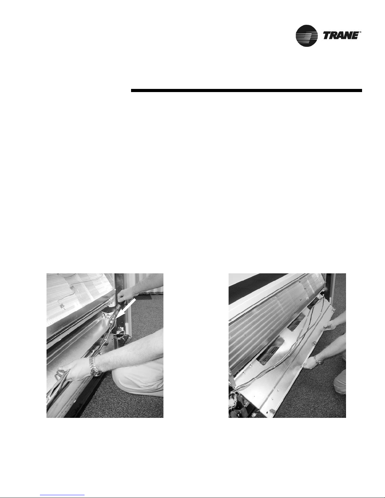
removed (Figures 50-52). AFter the
drain pan has been removed,
proceed to Step 5.
5. Remove the 2 screws at the lower
corners of the fan deck to release it.
(Figure 53)
6. Slide the fan board forward to
remove from the unit (Figure 54).
CAUTION: The fan board may need
to be supported to prevent it from
sliding forward and falling out of the
unit.
7. When reinstalling, use the same
steps in reverse order.
Lubrication: Fan Shaft
One fan shaft bearing is mounted on
the right end of the fan board. This
sleeve-type bearing has an inner surface of sintered bronze which allows oil
to flow from the built-in reservoir to the
bearing surface without the use of
grooves or holes in the inner bearing
surface. Do not alter the inner bearing
in any way.
Fill the bearing reservoir every six
months with a No. 10 SAE, non- detergent, automotive type oil. Use a pressure oiler. Add oil until seepage is
noted between the bearing and fan
shaft.
Lubrication: Motor Bearings
Motors are permanently lubricated and
do not require any further oiling.
Figure 53: Loosen the four bolts (2 & 2) at
either end of the fan board to begin board
removal.
Figure 54: Slide fan board forward to
remove.
Page 46
46 UV-SVN002-EN
Maintenance
Motor
The fan motor is a permanent split
capacitor type motor with 115V power
(Tables 7 and 8). If a replacement motor
is required, it should be ordered from
The Trane Company.
To replace the fan motor, complete the
following steps:
1. Turn off power to the unit and
remove the front cover.
2. Complete steps for return air grille
and filter removal.
3. Complete steps for removal of drain
pan if Face & Bypass option is
installed.
4. Complete steps for removal of fan
board.
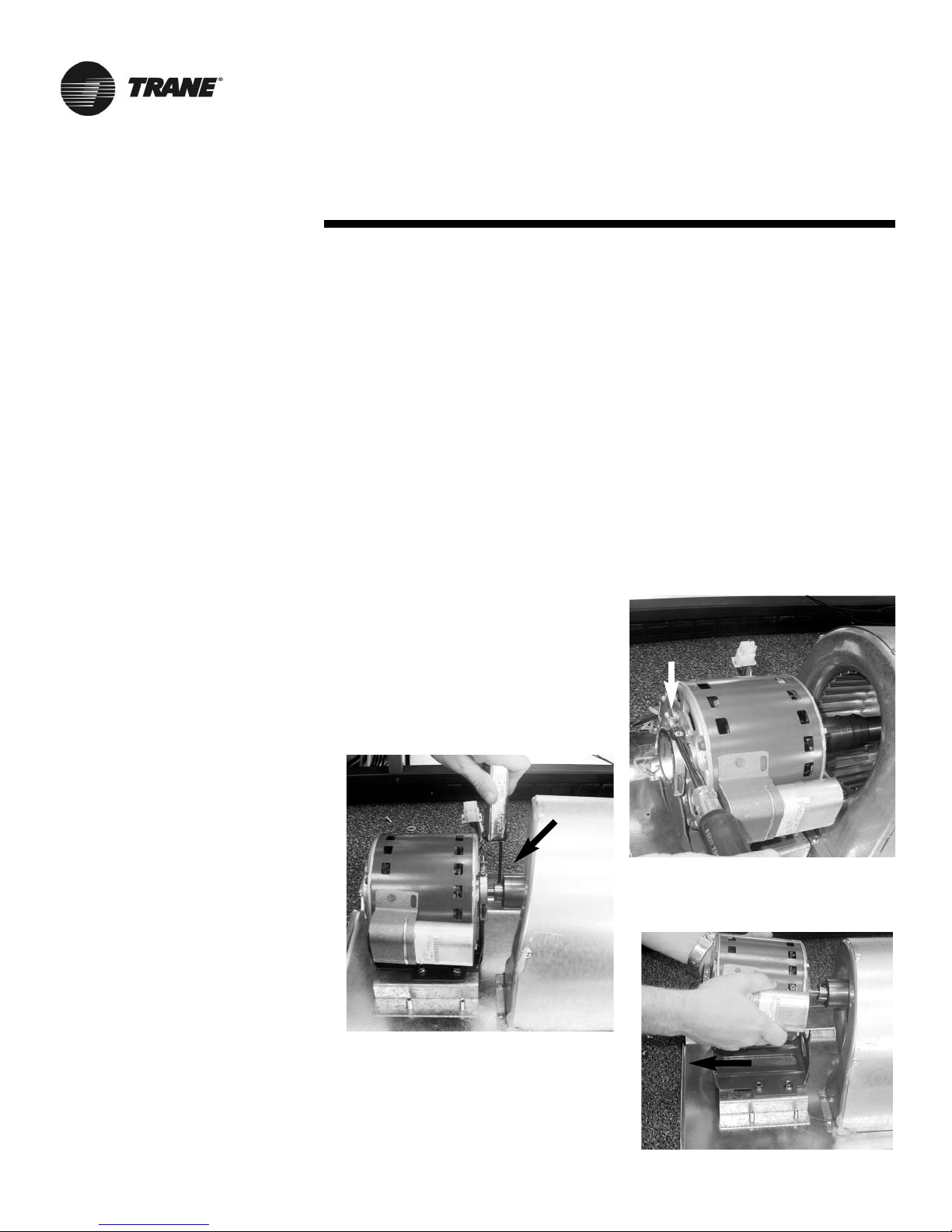
5. Disconnect the motor ground wire
6. Using a 7/16” Allen wrench, loosen
the coupling on the fan shaft.
7. Loosen the screw on the motor clamp
until it allow the motor to be lifted off
the base. (Figure 56)
8. Lift the motor and pull forward until
fan shaft separates from the motor.
(Figure 57).
9. Attach new motor to fan shaft and
reverse steps to complete installation.
Modulating Valves
The valve should be services by a
trained, experienced technician. For
detailed installation and removal steps,
refer to Pages 28 & 29 in this manual).
For general servicing or malfunction,
follow one of the appropriate steps:
1. If the valve is leaking, drain system
OR isolate valve from the system. DO
NOT remove valve body from
plumbing.
2. Check to see if the cartridge needs to
be replaced. If so, follow appropriate
steps explained for cartridge
assembly removal.
3. If the motor or other internal parts of
the actuator is damaged, replace the
entire actuator assembly.
NOTE: These hydronic valves are
designed and tested for silent operation. However, water noise may occur
as a result of high water velocity. Piping
noises may also occur in high temperature (over 212 F) systems with insufficient water pressure.
NOTE: Do not use petroleum-based or
mineral oil type boiler additives.
Compounds with a 50% water dilution
that can be used are diethylene glycol,
etheylene glycol and propylene glycol.
Preventive Maintenance
A comprehensive preventive maintenance program should be established
for a unit ventilator system. The following are several key elements:
• Inspect the filters monthly. .
• Inspect and clean the drain pans
every three months.
• Check the coils for ‘‘dirt’’ accumulation every three to six months.
• Clean the coils at least once each
year.
• Inspect the unit ventilator insulation
every three months; thoroughly clean
as needed.
Figure 55: Loosening coupling on the
fan shaft.
Figure 56: Loosening the clamp of fan
motor.
Figure 57: Remove the fan motor by
lifting up and pulling forward.
Page 47
UV-SVN002-EN 47
Troubleshooting
Trouble Shooting Analysis
WARNING:
Hazardous Service Procedures!
The maintenance and troubleshooting procedures recommended in
this section of the manual could
result in exposure to electrical,
mechanical or other potential safety
hazards. Always refer to the safety
warnings provided throughout this
manual concerning these procedures. When possible, disconnect all
electrical power including remote
disconnects before servicing. Follow
proper lockout/tagout procedures to
ensure the power can not be inadvertently energized. When necessary
to work with live electrical components, have a qualified licensed electrician or other individual who has
been trained in handling live electrical components perform these tasks.
Failure to follow all of the recommended safety warnings provided,
could result in death or serious
injury.
If operating difficulties are encountered, refer to the following for
probable causes and corrective
measures. If suggested corrective
measures have been taken, and the
trouble still persists, contact the
control supplier or the local Trane
Sales Office.
Heating
A. Room Too Warm --- Outside
Temperature Below 35 F.
1. Check the room thermostat to
make sure it is properly set.
2. If this occurs during the early
part of the day, it may be due
to the room thermostat giving
a false reading caused by room
walls still being cold from the
night temperature setting. To
correct, start the warm-up cycle
earlier in the morning to give
the wall a chance to come up to
room temperature before the
room is occupied.
3. If the thermostat is mounted on
a cinder block wall, the hole in
the cinder block could cause
cool air through the hole to
affect the thermostat. In this
case, the thermostat may need
to be relocated.
4. Check for proper operation of
the face and bypass damper or
coil control valve. If the damper
or valve appears to be functioning improperly, contact the
control contractor or, if Trane
controls, see CNT-SVX04A-EN
(Tracer
TM
ZN520 Unit Controller
IOP) for details on DDC
controls.
B. Room Too Warm --- Outside
Temperature Above 35 F.
1. Check the room thermostat to
make sure it is properly set.
2. Check for proper operation of
the face and bypass damper or
coil control valve. If the damper
or valve appears to be functioning improperly, contact the
control contractor or, if Trane
controls, see CNT-SVX04A-EN
(Tracer
TM
ZN520 Unit Controller
IOP) for DDC controls details.
3. Check the outside air damper.
The outside air damper should
be in the open position.
4. Check for a clogged filter. If the
filter is clogged, the restriction
of air flow may seriously
reduce the ventilation capacity
of the unit. Clean or replace the
filter.
5.
If the installation utilizes
Wall-Fin auxiliary radiation:
a.
Hot Water
--- if control of
water flow is provided, check
the control valve for proper
functioning.
b.
Boiler
--- Check the boiler
reset schedule to determine
if the loop temperature can
be decreased.
c.
Steam
--- Check the
operation of the control
valves.
6.
Check the outside air temperature
--- is it above 60-65 F?
The economics of the Unit
Ventilator selection dictate that,
in most cases, the unit will be
sized to provide adequate
natural (ventilation) cooling
with outside temperatures up
to 60-65 F. Above this point, a
changeover should be made to
the mechanical cooling cycle.
C. Room Too Cool
1. Check the room thermostat to
make sure it is properly set.
2. Check the air filter. If clogged,
renew or replace.
3. Check for proper operation of
the face and bypass damper or
coil control valve. If the damper
or valve appears to be functioning improperly, contact the
control contractor or, if Trane
controls, see CNT-SVX04A-EN
(Tracer
TM
ZN520 Unit Controller
IOP) for details on DDC
controls.
4. Check the outside air damper. It
should be closed or at a
minimum outside air setting.
5. On the hot water or steam type
units, check the boiler pressure
or temperature to make sure
that design requirements are
being met.
6.
If the installation utilizes WallFin auxiliary radiation:
Check the radiation controls for
proper operation.
Page 48
48 UV-SVN002-EN
Troubleshooting
Cooling
A. Room Too Hot
1. Check the room thermostat to
make sure it is properly set and
that the thermostat is in the
cooling cycle.
2. Check the outside air damper.
The damper should be at a
minimum outside air position.
3. Check for a clogged filter. This will
reduce air flow and unit cooling
capacity. If a clogged filter is
found, clean or replace it.
4.
For chilled water cooling
:
a. Check for proper operation of
the face and bypass damper or
coil control valve. If the damper
or valve appears to be functioning improperly, contact the
control contractor or, if Trane
controls, see CNT-SVX04A-EN
(Tracer
TM
ZN520 Unit Controller
IOP) for details on DDC controls.
b. Check the temperature of the
water leaving the chiller to
insure that it meets design
requirements.
Motor
If the motor fails to start and other
motors on the same circuit are functioning:
A. Check the unit switch to make
sure it is in the ‘‘ON’’ position.
B. Check for loose switch or motor
connections.
Have a qualified electrician check the
motor anytime it is operating improperly.
Page 49
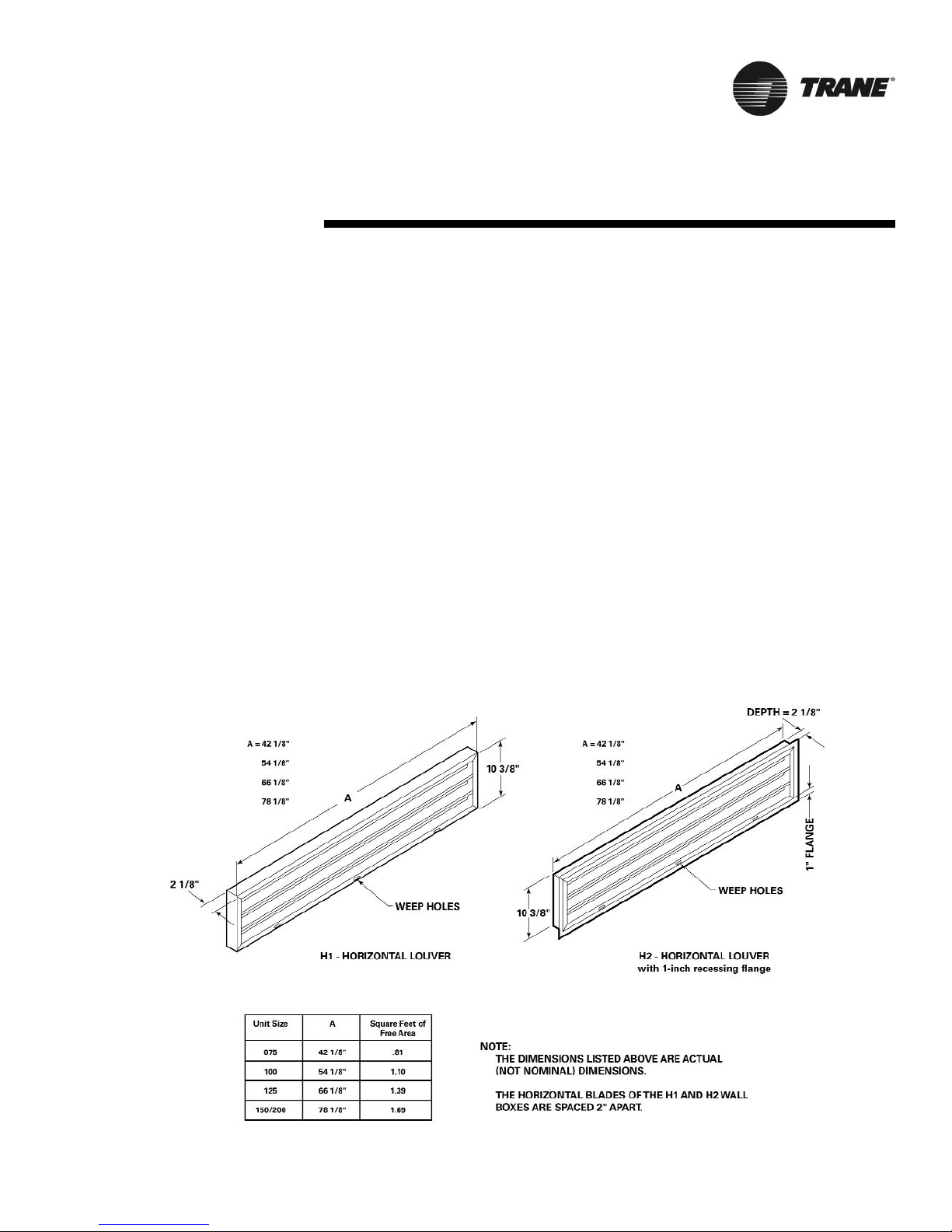
UV-SVN002-EN 49
Accessories Wall Boxes
General Information
The following instructions are general
recommendations for installing wall
intake boxes. Consult the architectural
plans for specific requirements.
Additional materials required to complete any specific installations (such as
duct connections, metal mounting
plates, or flanges)
are not furnished
by
Trane.
For best results, all air intake boxes
should be removable from outside of
the building. Weep holes must be at the
bottom to permit free drainage. A positive air and moisture seal should be
provided around all edges.
General Instructions
Trane wallboxes are illustrated in
Figures 58 & 59 and each lists the
wall openings required for wallboxes.
Vertical louvers in the wall intake box
provide extra strength for a high load
bearing capacity. The lintel may be
omitted on masonry wall installations.
Weep holes are provided in the outside
face of the bottom channel in the wallbox frame. Install all wall boxes to permit free drainage through the weep
holes to the outside of the building.
All wallboxes are furnished with diamond pattern expanded aluminum bird
screen.
Note: H1 (horizontal), V1 and V2 (vertical) wall models are all unflanged. H2,
V3 and V6 are flanged.
Figure 58: Horizontal wallbox
(H1 & H2) dimensions
Page 50
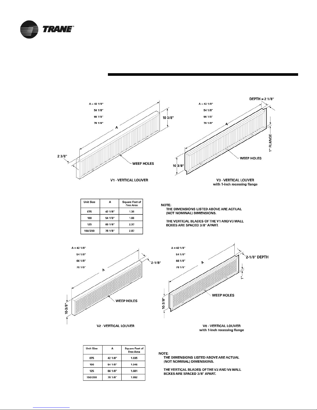
50 UV-SVN002-EN
Accessories Wall Boxes
Figure 59: Vertical
wallbox (V1, V3, V2 & V6)
dimensions
Page 51
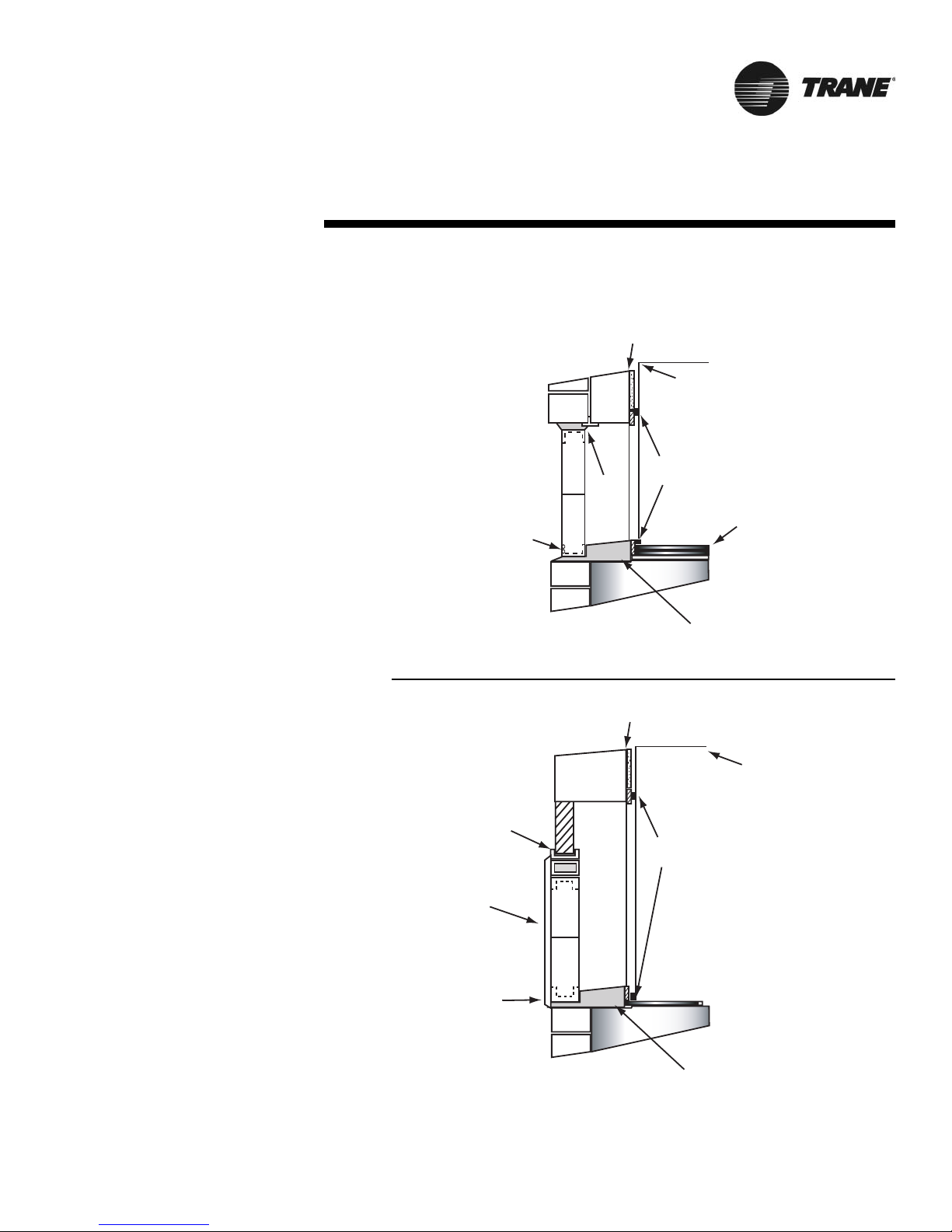
UV-SVN002-EN 51
Accessories Wall Boxes
Installation in Masonry Walls
A typical method of installing the wall
box in a masonry wall opening is illustrated in Figure 60.
Grout the top and bottom of the wall
box frame as noted. A sloped water
dam located in the space between the
unit and wall facilitates moisture
drainage. Grouting at the ends of the
intake box will complete the seal
between the wall box frame and the
masonry opening.
Installation in Curtain Walls
In all cases, the wall intake box should
be caulked to provide a tight, weatherproof seal. See Figure 61.
Note: A minimum of 2-1/8” of clearance
must be maintained between the exterior wall and back of the unit. Failure to
provide this gap will not allow the wall
box to fit properly.
Figure 60: Wallbox
installation in masonry
wall
Figure 61: Flanged wallbox
installation - 2” wall.
Outside
Wall
Weep
Holes
Interior Wall
w/ sheetrock
Rubber
Grout
Seals
Water dam sloped
toward exterior
Interior Wall
w/ sheetrock
Unit
Floor
Outside
Wall
Caulking
Rubber
Seals
Flanged
wallbox
Weep
Holes
Water dam sloped
toward exterior
Unit
Page 52
Other Accessories/
Related Literature
Literature Order Number SV-TD-UV-SVN02B-EN-02/05
Date February 2005
Supercedes SV-TD-UV-SVN002-EN-12/03
Stocking Location Inland
Trane has a policy of continuous product and product data improvement and
reserves the right to change design and specifications without notice.
Trane
A business of American Standard Companies
www.trane.com
For more information, contact
your local district office or
e-mail us at [email protected]
There are a number of accessories and optional add-ons that
can be ordered with the Classroom Unit Ventilator, including:
• Energy Recovery Units (ERSA)
• Classroom Unit Ventilator Shelving components
• Side-Wall Exhaust units
• Tracer ZN520 DDC unit controllers.
Each of these accessories is supported by its own Installation,
Diagnostics or Programming manuals. Please refer to the following Literature Reference list for related literature that may
be needed to complete your installation:
Related Installation Literature
• UV-SVN001-EN:
Classroom Shelving Model SHL IOD
• ERS-IOM-1:
Vertical Floor Energy Recovery Unit IOM
• SWE-IOM-1:
Vertical Floor Side Wall Exhaust IOM
• CNT-SVX04A-EN:
Tracer ZN520 Unit Controller IOP
R
 Loading...