

TRANE
R
Installation
Operation
Maintenance
IND-SVN01A-E4
(Jan 2010)
TRANE
R
TRANE Quantum
TM
Air Handler
Model: CLCPEuro
CLCPXP

TRANE
R

TRANE
R
Notice
World enviromental scientists have
concluded, based on the best currently
available evidence, that ozone in our
upper atmosphere is being reduced
due to the release of CFC fully
halogenated compounds.
The Trane Company urges that all
HVAC servicers working on Trane
equipment, or any manufacturer’s
products, make very effort to eliminate,
if possible, or vigorously reduce the
emission of CFC, HCFC and HFC
refrigerants to the atmosphere
resulting from installation, operation,
routine maintenance, or major service
on this equipment. Always act in a
responsible manner to conserve
refrigerants for continued use even
when acceptable alternatives are
available.
Refrigerant used in any type of airconditioning or refrigerating equipment should be recovered for reuse,
recovered and / or recycled for reuse,
reprocessed (reclaimed), or properly
destroyed, whenever it is removed from
equipment. Never release to the
atmosphere!
Safety Considerations
The equipment covered by this manual
is designed for safe and reliable
operation when installed and operated
within its design specifcation limits. To
avoid personal injury or damage to
equipment or property while installing
or operating this equipment, it is
essential that qualified, experienced
personnel perform these functions
using good judgement and safe
pratices.
See the following cautionary
statement.
Warning and Cautions
Notice that WARNING and CAUTION
appear at appropriate intervals
throughout this manual.
WARNING indicates a potentially
hazardous situation that could result
in personal injury or death.
CAUTIONs are designed to alert you
to conditions that could result in minor
personal injury or equipment damage.
i
WARNING
!
CAUTION
!

TRANE
R
Contents
General Information
Foreword
Warranty
Unit Description
Model Nomenclature
Receiving
Nameplate
Delivery Check
Resolving Shipping Damage
Storage Consideration
Outdoor Storage
Rigging and Handling
Rigging and Handling
Off Loading
Moving to Position On Site
Forlift Trucks
Roller Movement
Installation
Foundation
Erection
Assembly and Installation
External Connection
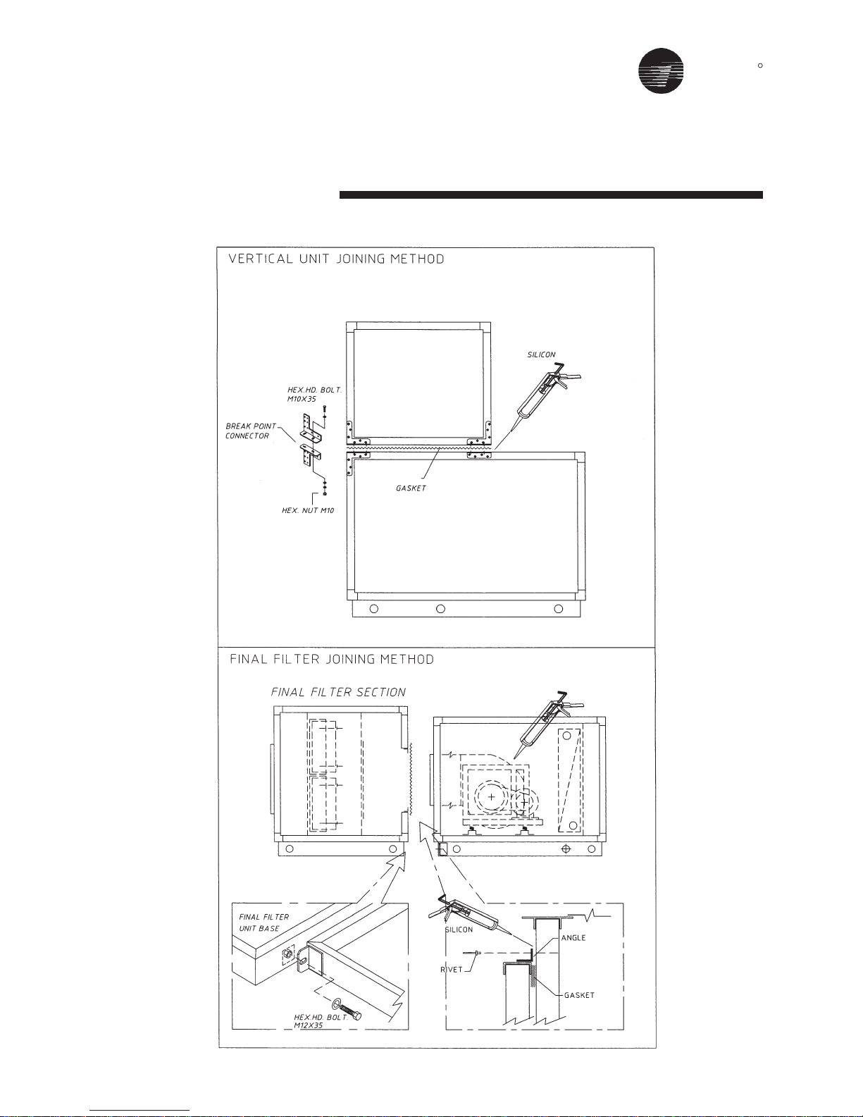
Frame to Frame Connection, CLCP-euro
Panel to Frame Connection, CLCP-euro
Paneling, CLCP-euro
Frame to Frame Connection, CLCP-XP
Panel to Frame Connection, CLCP-XP
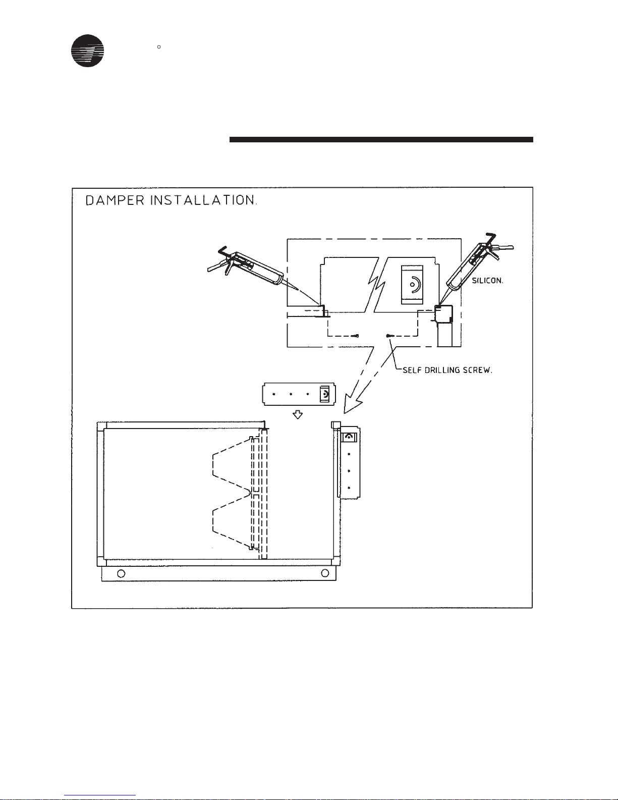
Vertical Unit / Final Filter / Damper Joining Method
Piping
Start-Up
Start-Up Procedures
Maintenance
Periodic Maintenance Checklist
Maintenance Plan
Trouble Analysis
General
Pulley and Belt
Appendix A-Unit Weight, CLCP-euro
Appendix B-Unit Weight, CLCP-XP
Appendix C-Fans and Arrangement
Appendix D-Filter ad Qty
Appendix E-Motor Performance Data
Appendix F-Typical Wiring Diagram
Safety Recommendations, Maintenance Contract and Training
Pre - Start Up Checklist
1
4
5
7
9
24
26
33
63
TRANE
R
General Information
• Foreword
These installations, operation and
maintenance instructions are given as
a guide to good practice in the
installation, commission into service,
operation and periodic maintenance
by the user, of TRANE Quantum
TM
Air
Handler. They do not contain full
service procedures necessary for the
continued successful operation of this
equipment; the services of a qualified
technician should be employed
through the medium of a maintenance
contract with a reputable service
company.
• Warranty
Trane’s standard warranty covers the
equipment. It does not cover damage
due to misuse, lack of maintenance,
or failure to comply with the
manufacturer’s instructions or
recommendations.
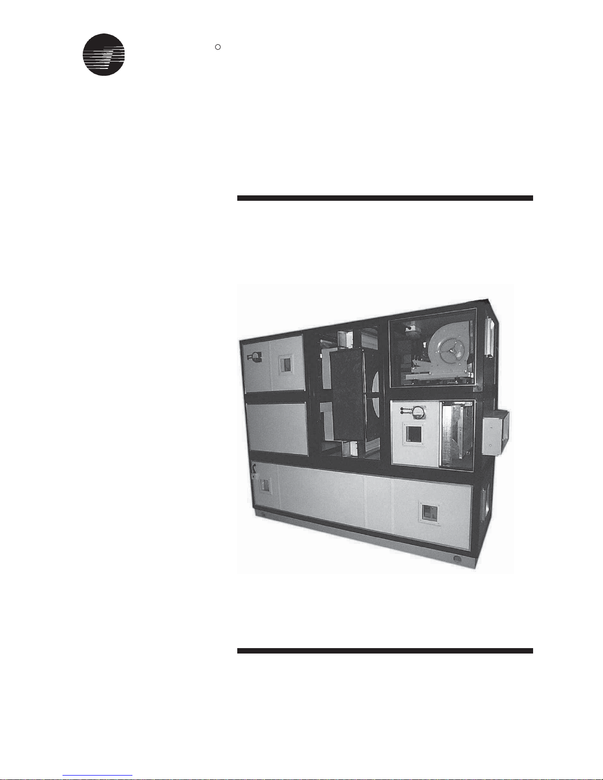
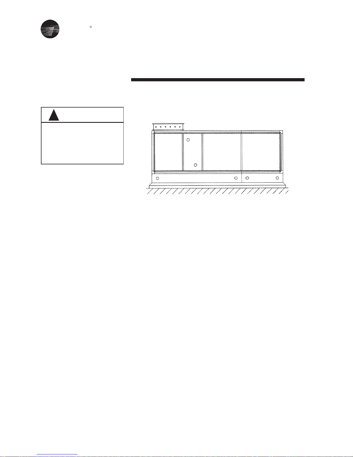
• Unit Description
TRANE QuantumTM Air Handler are
Central Station Air Handlers designed
for a variety of controlled air application.
The basic unit consists of a fan,
heating and/or cooling coils, filters and
air dampers. See product catalogue for
list of available modules and options.
The TRANE Quantum
TM
Air Handler are
designed for cooling load conditions
of 1000-65000 nominal CFM. Fans are
double width, double inlet, centrifugal
types with forward curved, backward
curved, and airfoil blade designs.
To insure fan motor assembly stability
the unit ships with shipping brackets
located between the fan support frame.
These spacers must be removed prior
to fan operation, to assure proper
vibration isolation.
Units ship as complete units, sections
or subassemblies. Each section is
provided with a nameplate (label)
which includes type of section, unit
serial number, customer tag number
and unit model number.
1
TRANE
R
2
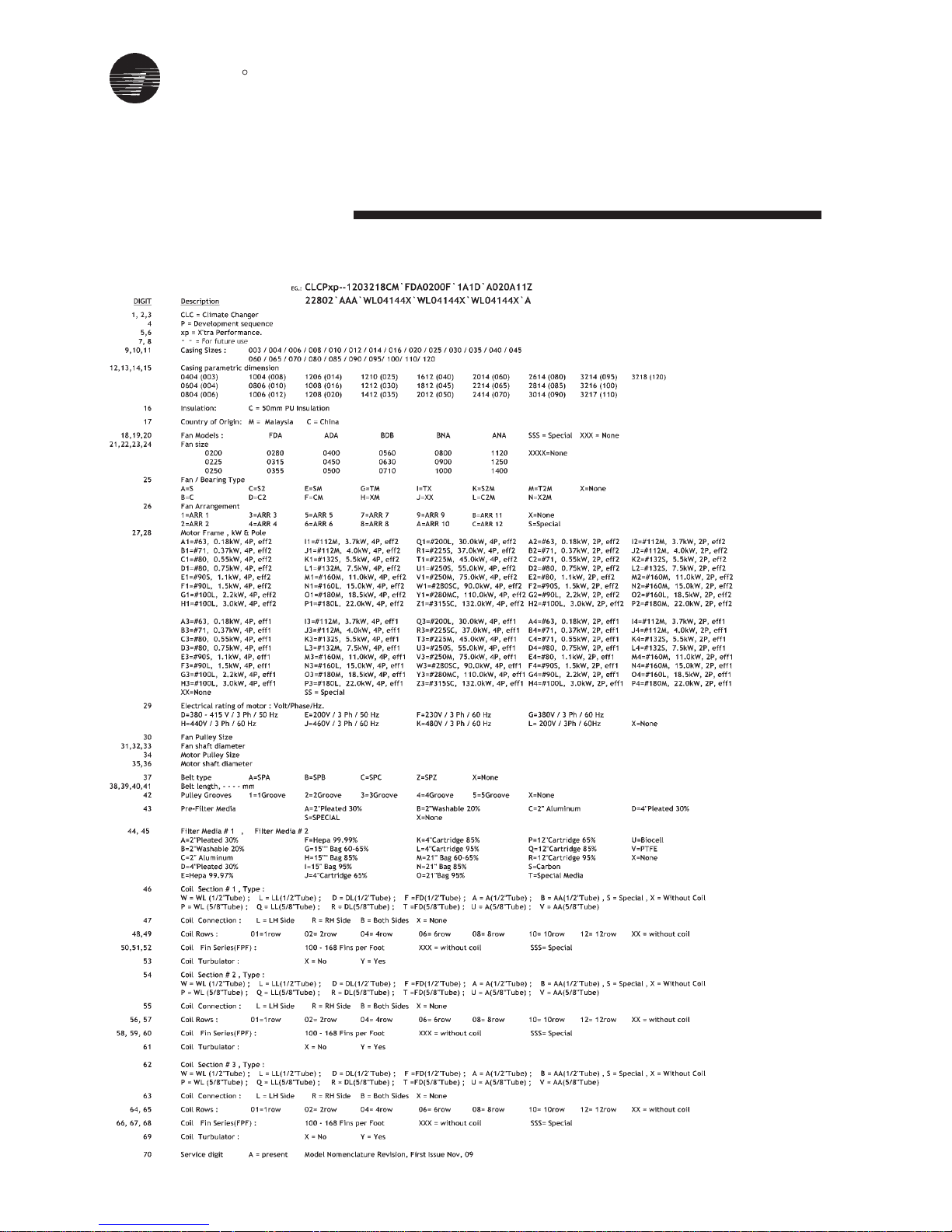
CLCPXP
Model Nomenclature
TRANE
R
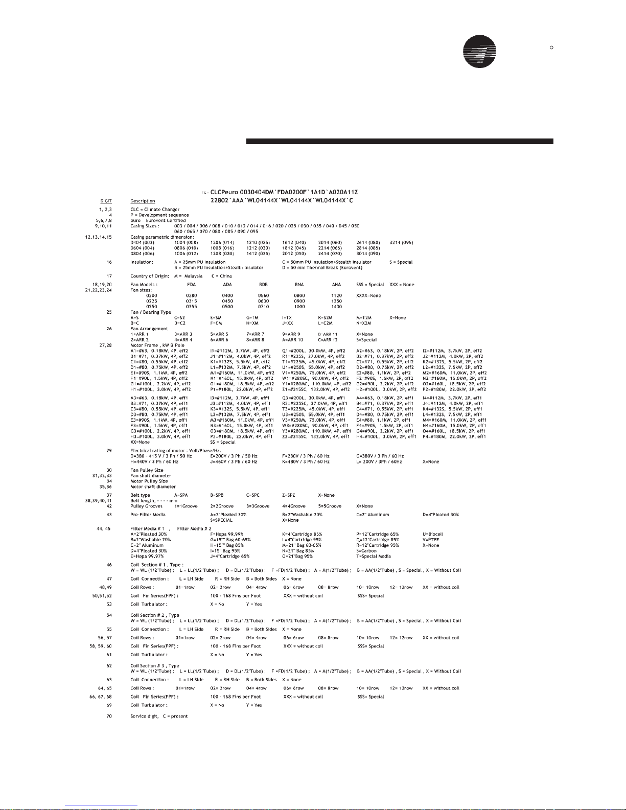
CLCPEURO
Model Nomenclature
3
TRANE
R
• Resolving Shipping
damage
If damage is found or items are
missing:
1. Report all claims of shipping
damage to the delivering carrier
(transporter) immediately, and
schedule an inspection.
2. Make specific notations concerning
the damage on the freight bill.
3. Keep damaged material in the same
location as received. It is the
receiver’s responsibility to provide
reasonable evidence that damage
was not incurred after delivery.
4. Photograph damage if possible.
5. Do not move or discard damaged
freight packaging materials.
6. Notify the Trane sales representative
of the damage and arrange for
repair. Do not attempt and arrange
for repair. Do not attempt to repair
the unit without consulting the sales
representative. TRANE IS NOT
RESPONSIBLE FOR SHIPPING
DAMAGE.
• Storage Considerations
When storing a TRANE QuantumTM Air
Handler, for a period of time before
installation, it must be protected. The
warranty will not cover damages to
the unit do to negligence during
storage. Indoor storage is ideal and
requires only a few special pre-
cautions.
To protect the unit from damage due to
the elements and prevent it from
possibly becoming a contaminant
source for indoor air quality (IAQ)
Receiving
problems, the unit should be stored
indoors.
When outdoor storage is necessary,
several things must be done to prevent
damage.
• Outdoor Storage
1. Select a well-drained area,
preferably a concrete pad or
blacktop surface.
2. Place the unit(s) on a dry surface or
raised off the ground to assure
adequate air circulation beneath unit
and to assure that no portion of the
unit contacts standing water at any
time.
3. Allow proper clearance around the
unit to perform periodic inspection
and maintenance of the equipment
while in storage.
4. Keep the equipment in the original
shipping container for protection
and ease of handling.
5. Cover the unit securely with a
CANVAS tarp.
6. Ensure that the canvas tarp is
secure.
7. Do not stack units.
8. Do not pile other material on the
units.
9. Loosen belt tension on drive belts.
4
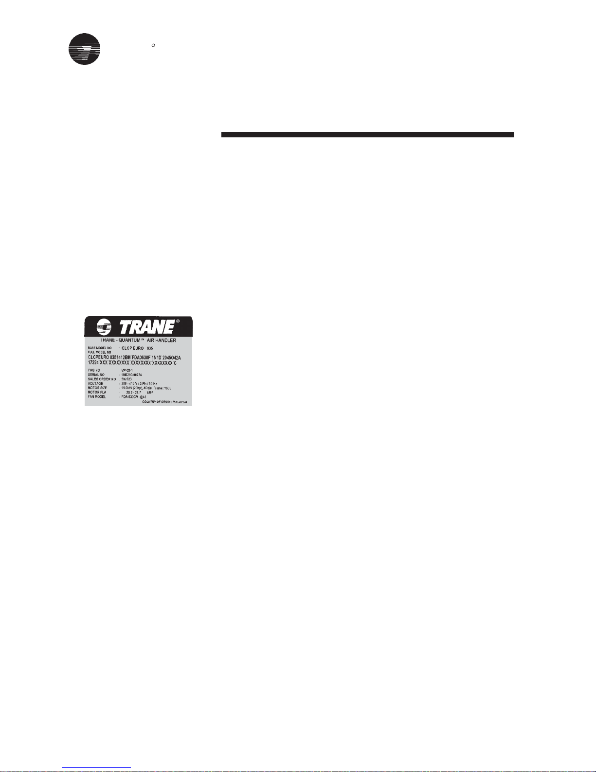
• Nameplate
All of TRANE QuantumTM Air Handler
are identified by a multiple-character
model number. lts use enables owner/
operator, installing contractors, and
service technicians to define the
operation, components and options for
a particular unit. Be sure to refer to the
information printed on the unit
nameplate (figure1) when ordering
replacement or requesting service.
• Delivery Check
All unit sections are securely fasten to
skids for shipping and handling
purpose.
Upon receipt of the unit(s), inspect for
damage that may have occurred during
shipment and any items, which were
ordered but did not arrive with the unit.
Complete the following checks:
1. Visually inspect the exterior unit
casing and all accessories for any
dents, punctures or shipping and
handling damage.
2. Cut all banding (if applicable) loose
from skid, but do not remove the
skids.
3. Check all access doors to confirm
that they are secured with latches.
4. Manually rotate the fan wheel to
ensure free movement of the shaft
and bearings
Inspect the fan housing for any
foreign objects.
5. Inspect the coil(s) for fin damage.
Figure 1
TRANE
R
Rigging and Handling
5
Rigging and Handling
Confirm that factory installed (if any)
attachment brackets are in place and
screws tight, before rigging. The unit
will ship either assembled or as
sections. Before preparing the unit for
lifting, estimate the approximate center
of gravity for lifting safety. Because of
placement of internal components, the
unit weight may be unevenly
distributed, with more weight in the coil
and fan area. Approximate unit weights
are given in Appendix A & B.
Always apply good rigging procedures
when lifting a unit. Before hoisting the
unit into position, be sure that a proper
method of rigging is used, with straps
or slings and spreader bars for
protection and safety during lifting.
Always test-lift the unit to determine
exact unit balance and stability before
hoisting it to the installation location.
DO NOT LIFT THE UNIT WITHOUT
TEST-LIFT FOR BALANCE AND
RIGGING. DO NOT LIFT THE UNIT
ABOVE PERSONNEL. FAILURE TO
OBSERVE THESE WARNINGS MAY
RESULT IN PERSONAL INJURY,
DEATH OR EQUIPMENT DAMAGE.
(See Appendix A & B for components
weight).
NEVER ASSEMBLE OR BOLT
SECTIONS OR SUBASSEMBLIES
TOGETHER BEFORE RIGGING.
ALWAYS RIG SECTIONS OR
SUBASSEMBLIES AS RECEIVED
FROM THE FACTORY.
Off Loading
A specific lifting method for offloading
the units is recommended as follows
(See Figure 2):
1. 75mm-diameter lifting holes,or
certified lifting lugs, are provided on
the unit base frame.
2. ALL LIFTING POINTS in one axis of
the unit must be used when
offloading and moving the unit.
3. Slings and speader bars are to be
provided by the rigger and attached
to ALL LIFTING POINTS.
4. The minimum rated lifting capacity
(vertical) of each sling and spreader
bar should be no less than the
shipping weight.
5. The unit must be lifted with care,
avoiding shock load by lifting the unit
slowly and evenly.
WARNING
!
Moving To Position On Site
TRANE QuantumTM Air Handler are
supplied in sections modules, flat
packed, or as a complete unit, in
accordance with the relevant assembly
drawings. Any necessary use of force
during unloading or movement of the
units must only be applied via the unit
base frame or shipping pallet.
NEVER LIFT THE UNITS BY COIL
CONNECTIONS OR BY ANY OTHER
PROTRUSIONS.
THE ROOF IS NOT DESIGNED TO BE
WALKED ON, BUT IF THIS IS
UNAVOIDABLE, ENSURE A MORE
EVEN WEIGHT DISTRIBUTION BY
THE USE OF BOARDS.
FAILURE TO DO SO MAY RESULT IN
SEVERE PERSONAL INJURY OR
DEATH.
Figure 2
WARNING
!
WARNING
!
WARNING
!
ENSURE SLINGS DO NOT FOUL ON
UNIT PROTRUSIONS.
THE CENTRE OF GRAVITY WILL
VARY PER UNIT... POSITION THE
SLING AND SPREADER BARS
CAREFULLY TO COMPENSATE FOR
THIS.
TRANE
R
Rigging and Handling
6
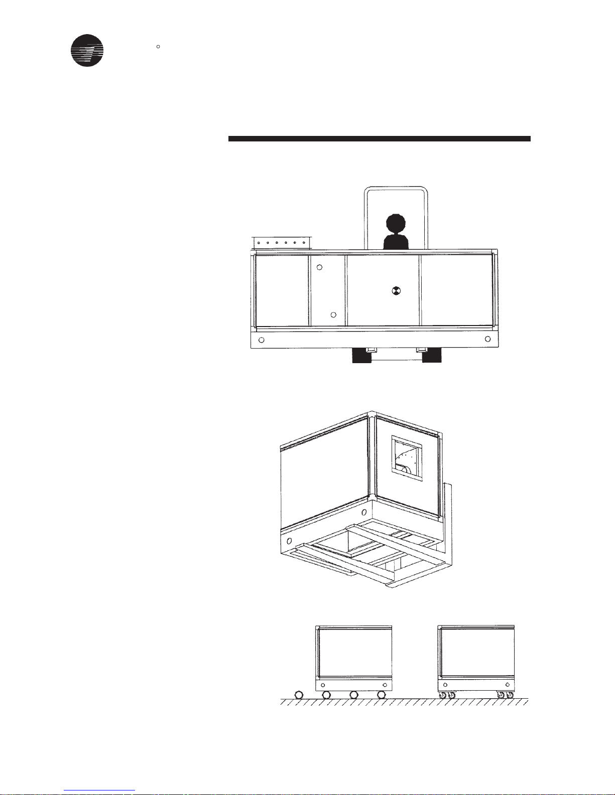
Forklift Trucks
The forks must only be applied under
the unit base frame and not against
the unit base frame. The lift point
should be as near as possible to the
centre of gravity (see Figures 3 and 4).
In the case of larger units the use of
several forklift trucks may be required.
Roller Movement
Units fitted with base frames may be
moved on roller trolley or tubular rollers
(see Figure 5).
Figure 3
Figure 4
Figure 5
TRANE
R
Installation
7
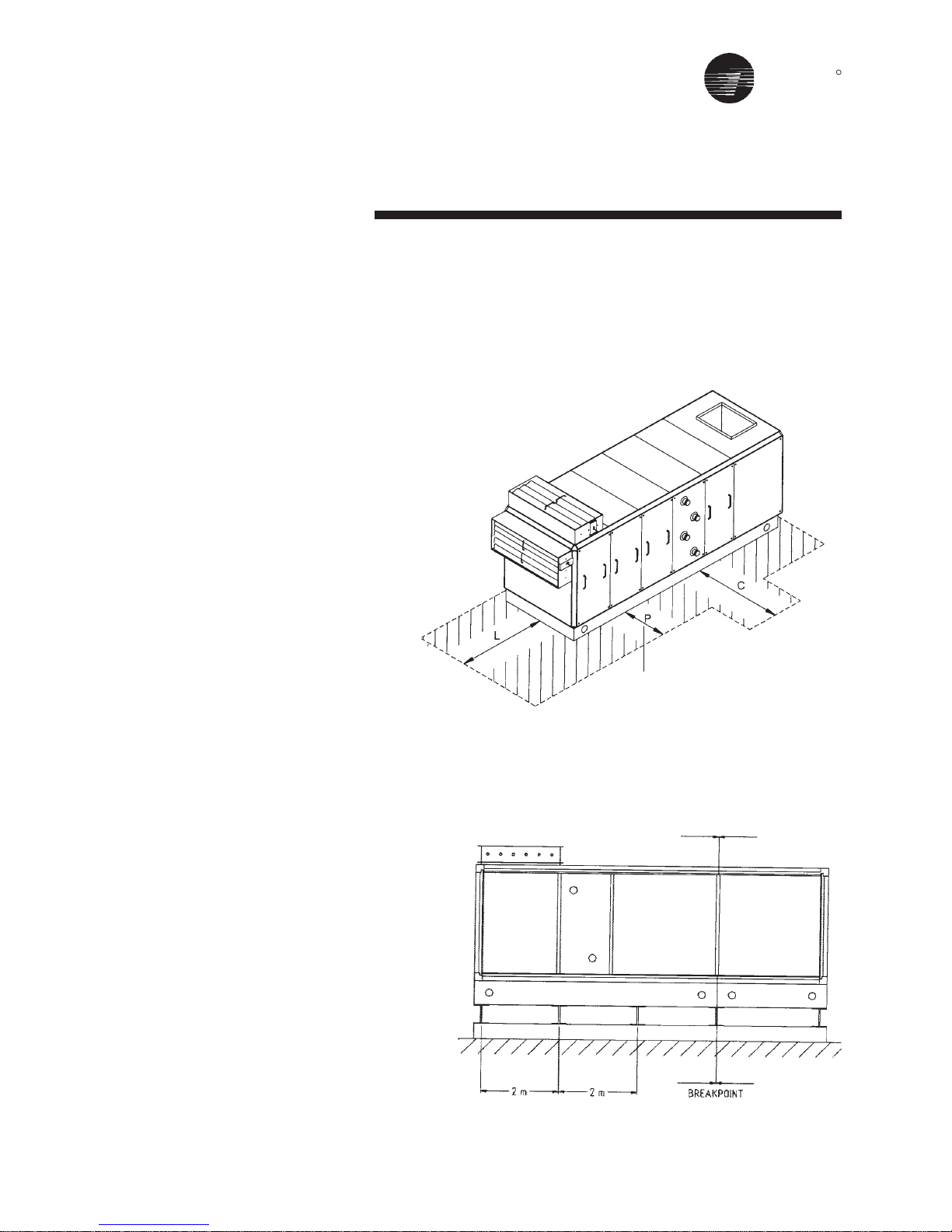
Foundation
When selecting and preparing the unit
site, follow these guidelines:
1. Ensure that the site can support the
total weight of the unit. Unit weight
figures only provide total gross
weights and do not include the
additional weight for water in any
coils.
2. Confirm that the foundation of the
mounting platform is large enough
to include the unit dimensions plus
service plus service access.
3. The floor or foundation must be
level for correct coil drainage and
condensate flow.
4. Provide adequate lighting for
maintenance personnel to perform
maintenance duties.
5. When the unit is positioned on site,
there must be sufficient space
around the unit to ensure that correct
operation and effective main-
tenance can be carried out. Figure
6 gives recommended space
allowances.
• On the designated access side of
the unit, working areas must have
minimum 1 mtr, space (P).
• Allowance for coil connections,
dimension “C” must be dimension
200mm + unit width.
• A clear unobstructed area before
and after an air intake or discharge
is required to ensure correct air
movement. The width of the area
must be >= the width of the unit, and
the depth (dimension “L”) must be
>= 0.5 x the overall unit height.
Complete reinforced concrete
foundations are suitable or strip
foundations may also be used (see
Figure 7).
In the case of strip foundations,
concrete or steel supports are
premissible, but support is required
under breakpoints and every 2 m along
the unit base.
Figure 7 - Air Handling Unit Steels Foundation
Figure 6
P = 1 MTR min
TRANE
R
Installation
8
Erection
To minimize noise transmission,
insulation material such as cork
slabbing (TICO pads) or rubber pad
may be placed between the unit base
and the foundation (see Figure 8).
Figure 8 - Air Handling Unit Plinth Foundation
IMPORTANT
!
FAILURE TO PROVIDE A LEVEL
PLINTH OR SUPPORT WILL
RESULT IN DOORS JAMMING
AND AIR LEAKS FROM THE
CASING.
TRANE
R
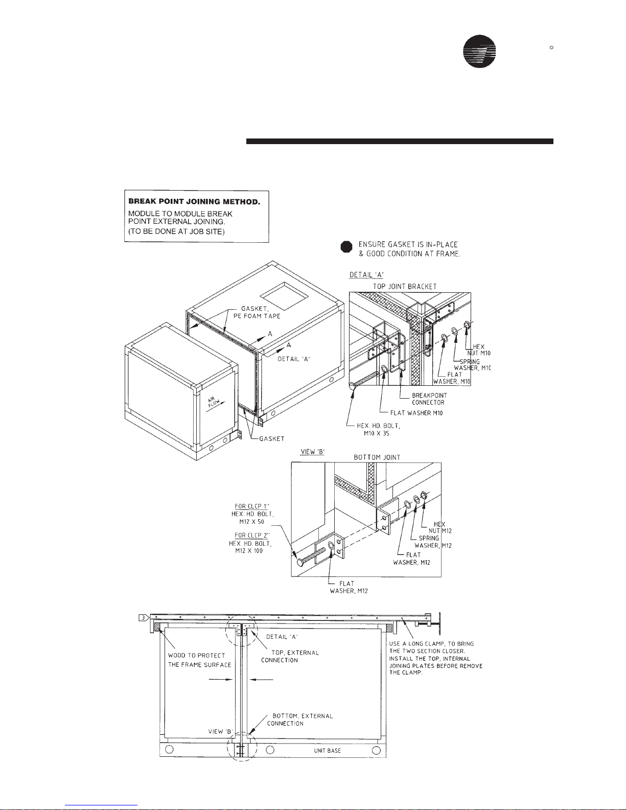
Assembly & Installation
CLCPEuro & CLCPXP
(External connection)
9
TRANE
R
Assembly & Installation
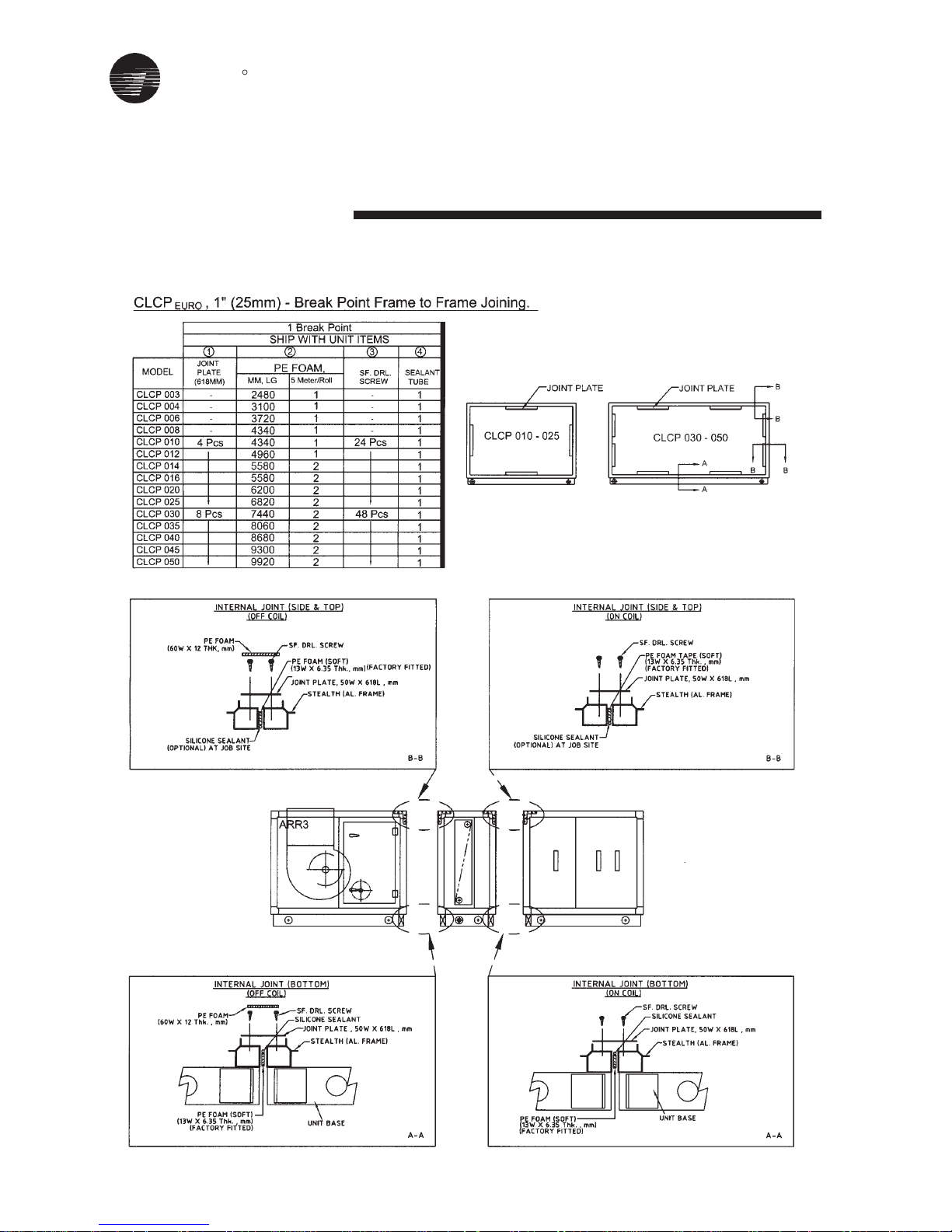
CLCPEuro Break Point (25mm) - Frame to Frame
10
TRANE
R
11
Assembly & Installation
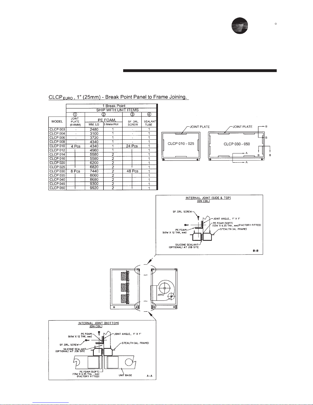
CLCPEuro Break Point (25mm) - Panel to Frame
TRANE
R
12
Assembly & Installation
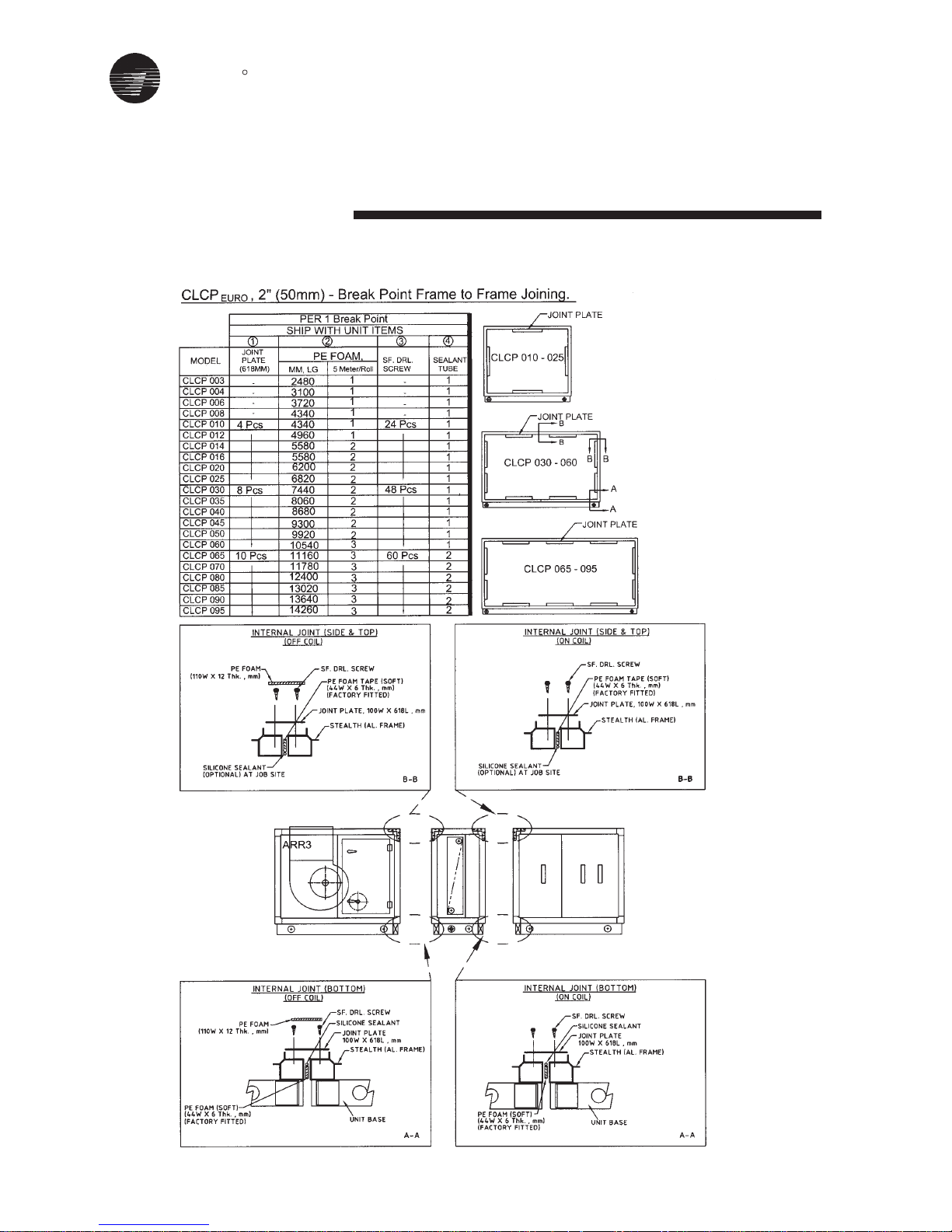
CLCPEuro Break Point 2” (50mm)- Frame to Frame
TRANE
R
Assembly & Installation
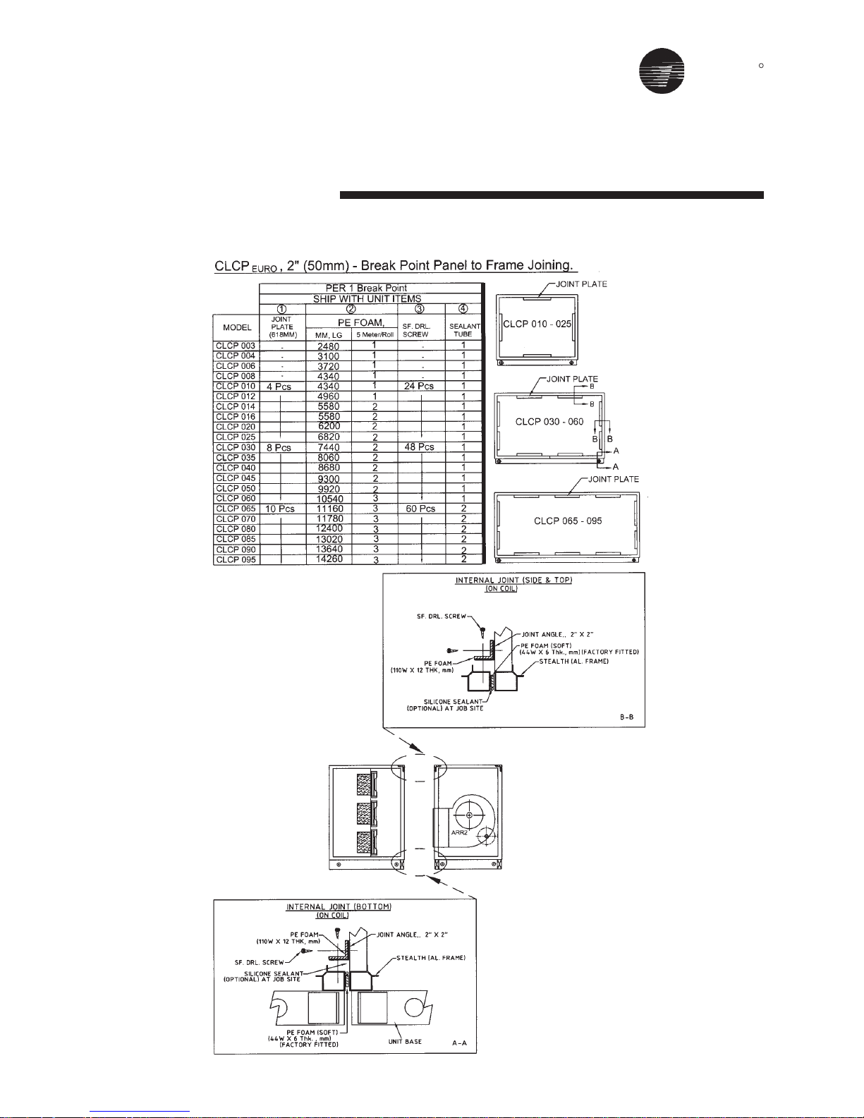
CLCPEuro Break Point 2” (50mm)- Panel to Frame
13

TRANE
R
Assembly & Installation
CLCPEuro Paneling
14
TRANE
R
Assembly & Installation
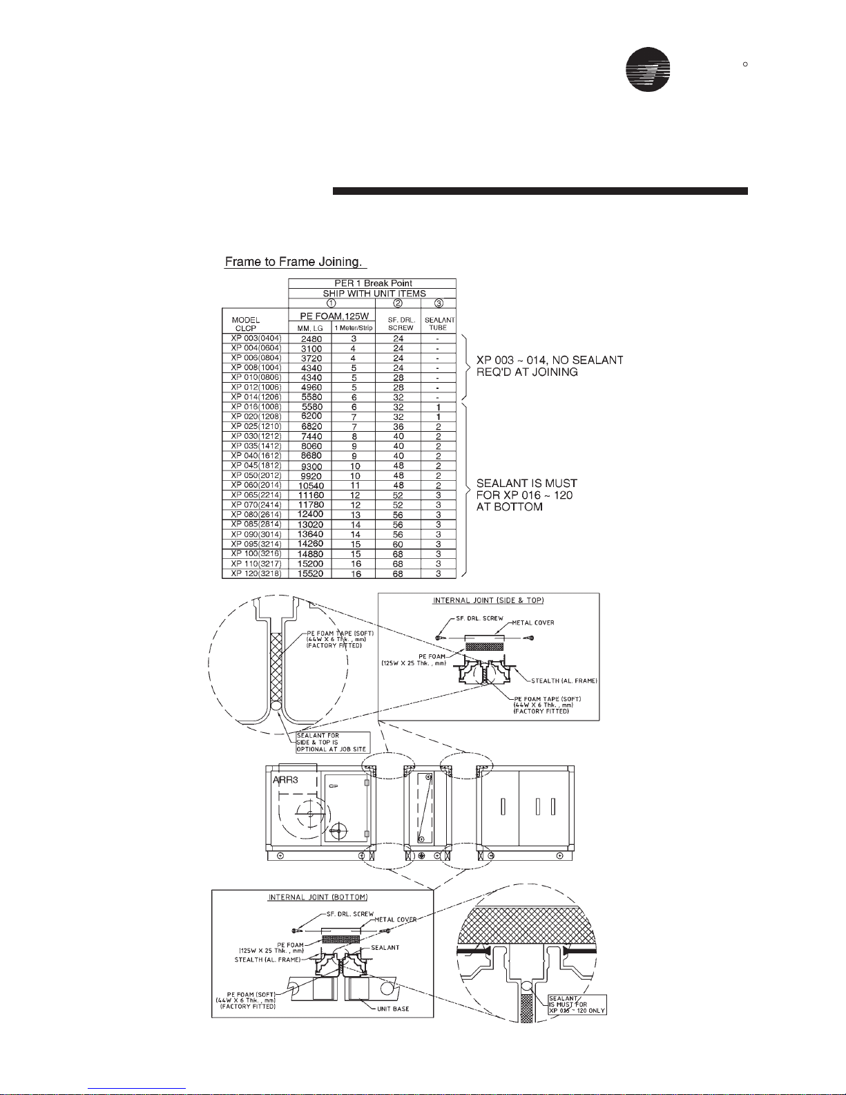
CLCP-XP - Break Point
15
TRANE
R
Assembly & Installation
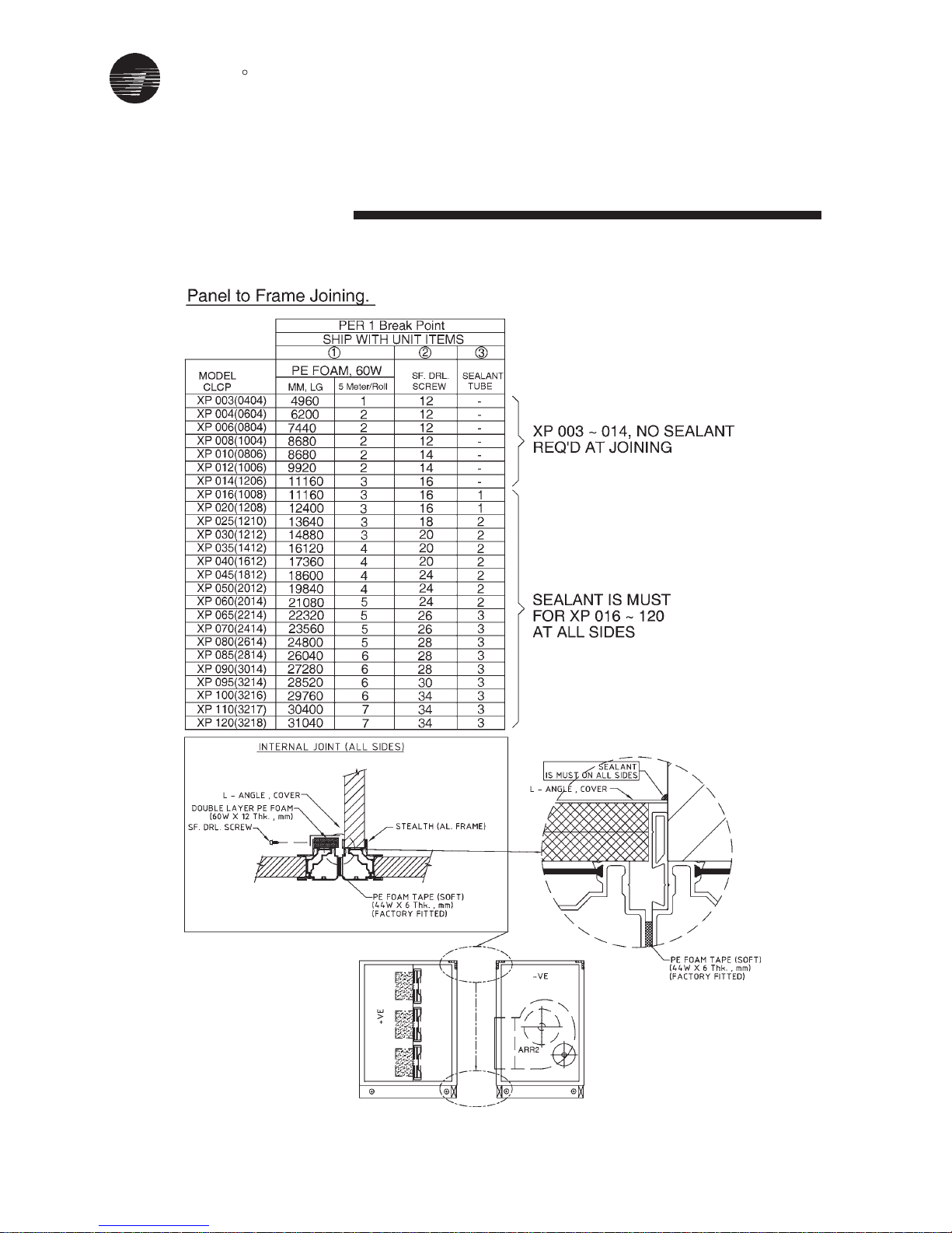
CLCP-XP - Break Point
16
TRANE
R
17
Assembly & Installation
CLCP
TRANE
R
Assembly & Installation
CLCP
18

TRANE
R
19
Assembly & Installation
Piping - Condensate Drain
Pan Connections
On cooling section(s) the drain pan
should always be connected directly
to a trap to ensure proper drainage of
condensate.
Male-threaded, 1-1/2" BSPT condensate drain connection is provided on
one side of the coil section. The main
drain lines and trap must be the same
size as the drain connection.
Pitch the connection line horizontal or
downward toward an open drain and
install a plugged tee to facilitate
cleaning. Condensate lines should not
be connected to a closed drain. This
is to avoid the possibility of drawing
sewer gasses into the unit.
Drain traps must be primed. lf they
are not, the trap is essentially nonexistent and the drain pan will likely
overflow.
CAUTION
!
Units With More Than One
Drain Pan
With the Trane QuantumTM Air Handler,
each module can be ordered with or
without a drain pan.
When more than
one module has a drain pan, you must
trap each module individually.
Connecting all drains to a common line
with only one trap will result in
condensate retention, and possible
water damage to the air handler or
adjoining space.
If a module has a drain pan for cleaning
purposes only, it does not need a trap;
however a cap or shut off valve should
be installed on the drain connection.
Only modules handling condensate,
such as a cooling coil module or
eliminator module, require a trap.
Figure 9
through
Figure 10
are
examples of typical installations.
IMPORTANT
!
Figure 9
Drain Pan Trapping for module under Negative Pressure
H = (1” for each 1” of
maximum negative
pressure) + 1”
J = 1/2 H
L = H + J + Pipe diameter +
Insulation
Figure 10
Drain Pan Trapping for module under Positive Pressure
K = min. 1/2”
H = 1/2” plus maximum
total static pressure
Failure to provide adequate
condensate piping may result in
water damage to the equipment or
building.
The applicable "rule of thumb" for
amount of condensate may as high
as 6 lbs/hr/ton for units serving areas
with high latent heat.

TRANE
R
Assembly & Installation
Chilled Water
Piping - Coil Connection
General Coil Piping Recommendation
Refer to Figure 11 for typical cooling /
heating and steam coil piping.
Proper installation, piping and trapping
is necessary to assure satisfactory coil
operation and to prevent operational
damage. Water inlet and outlet
connections protrude through the coil
section side panel. Follow standard
piping practices when piping to the
coil. Note the following:
1. Support all piping independently of
the coils.
2. Provide swing joints or flexible
fittings in all connections that are
adjacent heating coils in order to
absorb thermal expansion and
contraction strains.
3. When attaching piping to the coil
header, make the connection only
tight enough to prevent leaks, the
maximum recommended torque is
200ft-lbs.
4. Teflon tape or teflon piping
compound should not be used
because of its high lubricity, teflon
makes it easier to tighten the pipe
to the header joint past the point
where an effective seal is created,
thus damage to the coil could result.
5. "White Zinc" compound / pipe
sealer on all threaded connection
is recommended, instead.
20
NOTE: DRAIN AND VENT CONNECTIONS ARE PROVIDED AS
STANDARD ON COIL HEADERS.
IF EXTENDED DRAINS AND VENTS
ARE REQUIRED, THEY MUST BE
FIELD PROVIDED
.
Figure 12
Completely stress-free connections
are essential. The pipework of the coils
should be arranged to facilitate easy
removal of the coil for any required
maintenance purposes.
Figure 11
Typical Piping for Water Coil
IMPORTANT
!
To avoid damaging the coil
connections it is essential to grip
the pipe connection whilst
applying counter pressure to
tighten the joint (see Figure 12).
Use “Back-up wrench” when
attaching piping to coils, on
threaded connections.

TRANE
R
5.
6.
7.
8.
9.
10.
Assembly & Installation
Steam Coil Piping
Type A, AA Steam Coils
These are for central system, industrial
and process application with one row,
opposite-end connections. Maximum
standard operating limits:
Copper tubes: 100 psig and 400oF
Type AA coils feeds alternate tubes.
Refer to Figure 13 for typical steam coil
piping.
1. lnstall a 1/2 inch, 15 degree swing
check vacuum breaker in the
unused condensate return tapping
as close as possible to the coil.
2. Vent the vacuum breaker line to the
atmosphere or connect it to the
return main at the discharge side of
the steam trap.
Note: Vacuum breaker relief is
mandatory when the coil is controlled
by a modulating steam supply or a two-
position (ON-OFF) automatic steam
supply valve.
3. Run the return pipe at the full size of
the steam trap connection except for
the short nipple screwed directly
into the coil condensate connection.
Do not bush or reduce the coil return
tapping size.
4. Proper steam trap selection and
installation is necessary for
satisfactory coil performance and
service life. For installation, use the
following steps:
• Select trap based on maximum
possible condensate rate.
• Locate the steam trap discharge
at least 12 inches below the
condensate return tapping, this
provides sufficient hydrostatic
head pressure to overcome trap
losses and assure complete
condensate removal.
• Float and thermostatic traps are
recommended because of gravity
drain and continuos discharge
operation.
• Use float and thermostatic traps
are recommended because of
gravity drain and continuos
discharge operation.
• Use float and thermostatic traps
with atmospheric pressure gravity
condensate return, with automatic
control or where the possibility of
low-pressure supply steam exists.
• Use bucket traps ONLY when the
supply steams in unmodulated
and 25 psig or higher.
• Always install strainers as close
as possible to the inlet side of the
trap. Do not modulate Type A, AA
coils. Use two position (ON-OFF)
steam supply controls.
Use a V-port modulating valve to
obtain gradual modulating action.
Do not modulate systems with
overhead or pressurized returns
unless the condensate is drained
by gravity to a receiver (vented to
the atmosphere) and returned to
the main by a condensate pump.
At start-up on units with fresh air
dampers, slowly turn the steam on
full at least 10 minutes before
opening the fresh air.
Pitch all supply and return steam
piping down minimum of 1-inch
per 10 feet in the direction of flow.
Do not drain the steam mains or
take-off through the coils. Drain the
mains ahead of the coils through
a steam trap to the return line.
Overhead return require 1 psig of
pressure at the steam trap
discharge for each 2 - feet
elevation to assure continuous
condensate removal.
AV - Automatic or manual air vent
GV - Gate valve
VB - Vacuum breaker
OV - Automatic two-position control valve
21
Figure 13
Typical Piping for Steam Coil
MV - Magnetic valve
FT - Float and thermostatic steam trap
ST - Strainer
CAUTION
!
Condensate must flow freely from
coil at all times to prevent physical
coil damage from water hammer,
unequal thermal stresses, freeze-up
and/or corrosion.
Complete the following recom-
mendations to prevent coil
damage.
CAUTION
!
Caution: Always open the steam
supply control valve slowly to
prevent possible coil damage.

TRANE
R
coil as possible. Base filter-
drier selection on a minimum
pressure drop of 2 psi at the design
condition.
1. Install moisture indicator/sight
glass between the expansion valve
and filter-drier. The moisture
indicator/ sight glass must be sized
to match the size of the liquid line at
the thermal expansin valve.
2. Size liquid line shutoff valve with an
access port using the selected liquid
line OD, and install it close to the
condenser.
3. Minimize use of other valves, tube
bends and reducers since these
items tend to increase pressure
drop and to reduce subcooling at
the expansion valve.
4. The Thermal Expansion Valve (TEV)
must be selected for proper size
and capacity. The size of the TEV
should cover the full range of
loadings. Check that the valve will
successfully operate at the lightest
load condition. Select expansion
valves with external equalizer
connections, and those designed
to operate against a back pressure
of 20 pounds per square inch
higher than actual evaporator
pressure.
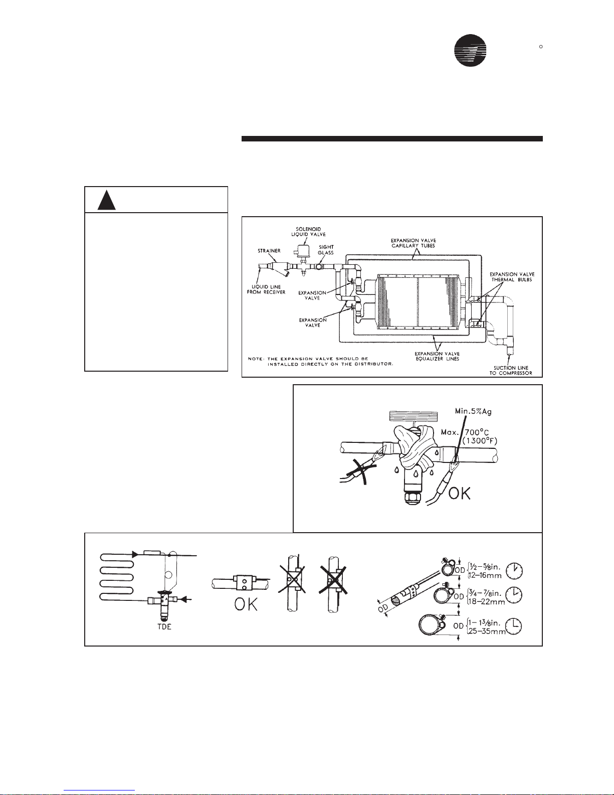
5. Install the TEV directly in the coil liquid
connection (distributor) provided.
The liquid distributor must be in a
true vertical position.
Suction Line Components
Install suction line pressure tap on the
leaving side of the evaporator coil near
the TEV sensing bulb location.
Accurate superheat measurement and
thermal expansion valve adjustment
demands that suction pressure be
22
Assembly & Installation
Refrigerant Coil Piping
TYPE FD COILS HAVE BEEN
DEHYDRATED AND CHARGED WITH
A HOLDING CHARGE OF DRY
NITROGEN. 10-20 PSIG TO
PREVENT LEAKS AND SYSTEM
CONTAMINATION, DO NOT BREAK
THE SEALS UNTIL THE COIL IS
INSTALLED.
1. Follow accepted refrigeration piping
practices and safety precautions for
typical refrigerant coil piping and
components.Specific recommen-
dations are provided with the
condensing units, including
instructions for pressure-testing,
evacuation, and system charging.
General recommendations for
component selection and line
sizing follow.
2. Leak-test the entire refrigeration
system after all piping is complete.
3. Charge the unit according to
approximate weight requirements,
operating pressures and super-
heat / subcoling measurements.
4. Adjust the thermal expansion valve
setting if necessary.
General Refrigerant Piping
Recommendations
IMPORTANT: REFER TO THE NOTE
ON THE INSIDE FRONT COVER OF
THIS MANUAL REGARDING
HANDLING OF REFRIGERANTS.
Liquid Line Components
Trane recommends the use of a
properly sized liquid line filter-drier
installed upstream from the expansion
valve and as close to the evaporator
measured near the evaporator coil.
Liquid Line Sizing
All compressors have a Refrigerant
Charge Limit (RCL) that must not be
exceeded. Since the RCL and
pressure drop are in direct conflict with
each other, Trane recommends that the
liquid line be sized as small as
possible, while maintaining a low
enough pressure drop to ensure
5°F(3°C) of subcooling at the
expansion valve.
Suction Line Sizing
Suction line tubes must be sized to
maintain refrigerant vapor velocities
that are high enough to ensure oil
entertainment under all operating
conditions.
It is not necessary to pitch horizontal
suction lines toward the compressor
when refrigerant coils is used with
Trane condensing units that are
designed with a gas trap in the suction
line just prior to the compressor.
TRANE
R
23
Assembly & Installation
Figure 14
Typical Piping for Refrigerant Coil
To avoid equipment malfuntion,
use care when brazing or solder-
ing so that distributor tubing is not
restricted or blocked. To braze
Thermostatic Expansion Valves
(TXV) avoid direct flame (figure 15)
to the valve body and avoid
excessive heat on diaphragm. As
an extra precaution. a wet cloth may
be around the body and element
during brazing operation.
CAUTION
!
Figure 15
Solder Technique
Note: Flame should heat away from
TXV element

TRANE
R
Start - Up
Perform the following steps prior to
starting the unit.
1. Inspect electrical connections. They
should be clean and secure.
Compare actual wiring with specific
diagrams provided on the unit.
2. Check piping and valves for leaks.
Open or close the valves to check
for proper operation. Drain lines
should be open.
3. If equipped with a refrigerant coil,
charge and leak-test the unit and
get it ready for operation according
to instructions provided with the
condenser equipment.
4. Check that all air filters are in place
and positioned properly. Under
Periodic Maintenance, see section
titled “Air Filters.”
5. Close and secure all unit access
doors. Check that the latch set
screws are tight.
6. Remove all foreign material from the
CAUTION
!
drain pan and check drain opening
and condensate line for obstruc-
tions.
7. Prime the DRAIN TRAP.
Start-up Procedures
After completing all start-up checks
and procedures, the unit may be
started. The following checks and
adjustments should be made during
initial start-up:
24
The use of untreated or
improperly treated water
in unit coils may cause
scaling, erosion, corrosion, algae, smile or other
equipment damage.
Consult a qualified water
treatment specialist to
determine if water
treatment is required. The
Trane Company assumes
no respon-sibility for
equipment damage
caused by untreated or
improperly treated water.
If the unit was stored for an extended
period of time, the following items
should be checked before starting the
unit.
1. Inspect motor bearings for moisture
and rust. Replace bearings if
necessary and repack with new
grease.
2. Check motor winding. An
acceptable winding resistance
reading is from 6 meg-ohms to
infinity. If reading is less than
5 meg-ohms, winding should be
dried out in an oven or by a
blower.
3. Inspect the entire motor for rust and
corrosion.
4. Lubricate the motor as instructed in
the section titled “Periodic
Maintenance,” or as indicated by the
maintenance tag on the motor.
5. Bump-start unit and observe the fan
wheel for proper rotation, as
indicated by rotation arrow located
on fan housing.
6. Measure the motor voltage and
ampeage on all phases to ensure
proper operation. The readings
should fall within the range given
on the motor nameplate.
Maximum allowable voltage imbalance
is two percent. Voltage imbalance is
defined as 100 times the sum of the
deviation of the three voltage from the
average, divided by twice the average
voltage. For example, if the three
measured voltages are 221, 230 and
227, the average would be 226 volts.
WARNING
!
Disconnect electrical
power prior to access into
a fan or ductwork. Even
when locked out
electrically, fans may
cause injury or damage if
the impeller is subject to
“wind-milling.” The
impeller should be
secured to physically
restrict rotational movement. Failure to secure
impeller can cause severe
personal injury r death.
Disconnect electrical
power source when
connecting or disconnecting electrical wires for
test procedures. Do not
open service access
doors while the unit is
operating. Failure to
exercise caution or while
inspecting. unit operation
may result in injury or
death from electrical
shock, air movement or
rotating parts.

TRANE
R
Sheave Alignment
Align the fan and motor sheaves by
using a straightedge. The straightedge
must be long enough to span the
distance between the outside edges
of the sheaves. For more details refer
to maintenance section.
Start - Up
25
The percent of voltage imbalance is
then calculated:
In this example, 2.2 percent imbalance
is not acceptable and the power
company should be notified to correct
it.
7. Check unit vibration if the fan speed
is changed more than 5% from the
original designed rpm, or if parts
such as shafts, fan wheels, bear-
ings, or other drive components are
replaced. Do not exceed max. fan
rpm.
8. Pay particular attention to any
vibration, noise or overheating of the
motor and fan bearings.
(Bearings may run warm during
break in.)
Excessive Vibration
EXCESSIVE VIBRATION MUST BE
CORRECTED TO PREVENT BEARING AND SHAFT DAMAGE. SEE THE
SECTION TITLED “TROUBLESHOOTING” FOR DETAILS ON THE
COMMON CAUSES FOR VIBRATION.
Determine Fan RPM
Fan rpm can be determined by using a
strobe-type tachometer, or revolution
counter.
100 x {[226-221] + [230-226] + [227-226]}
2 x 226
= 2.2% (Unacceptable)

TRANE
R
Maintenance
Periodic Maintenance
Checklist
The following checklist describes the
suggested maintenance schedule to
maintain proper operation of the unit.
Detailed procedures for owner-
operator maintenance checks are
given after this checklist.
After 48 Hours Operation
Belts have acquired their permanent
stretch. Readjust but do not overtighten.
Weekly
Observe unit weekly for any change
in running condition and any unusual
noise.
Every Month or weekly
Check air filters. Clean or replace if
clogged or dirty. Change bag filters
when pressure drop is 1-inch W.G.
Every Three to Six Months
Check greasing on fan and motor.
Align fan and motor sheaves (pulley).
Tighten sheaves setscrews to the
proper torque.
Check and adjust fan belt tension.
Tighten electrical connection.
lnspect coils for dirt build-up or coil
freeze up
Every Year
lnspect the unit casing for corrosion.
lf damage is found, clean and repaint
the surface with a rust-resistant primer
and vinyl chlorinated lacquer.
Clean the fan wheels and fan shaft.
Remove rust with emery cloth and
apply a coat of LPS#3 or an equivalent.
lnspect the condensate drain pan
and drain line, remove sludge or
foreign materials that might obstruct
proper drainage. Remove obstacles.
Check damper linkages, set-screws
and blade adjustment for proper
damper operation.
lnspect the control and power box
wiring for secure connections and
insulation.
Rotate the fan wheel and check for
obstruction in the fan housing. The
wheel should not rub on the fan
housing. Adjust the center if necessary
and tighten wheel setscrews to the
Disconnect electrical power prior to
access into fan or ductwork. Even
when locked out electrically, fans
may cause injury or damage if the
impeller is subject to "windmilling".
The impeller should be secured to
physically restrict rotational
movement can cause severe
personal injury or death.
proper torque.
Check condition of gasketing and
insulation around unit, door and
damper.
Examine flex connections for cracks
or leaks. Repair or replace damage
material.
WARNING
!
26
Disconnect electrical power and
allow rotating parts to stop before
servicing the unit. Exercise caution
if unit must be on for test or
maintenance procedures. Failure to
do so may result in injury or death
from electrical shock or moving
parts.
WARNING
!
IMPORTANT
!
Small & Medium size fans are
furnished shielded bearings. The
bearings are lubricated for life
and maintenance free. If re-
lubrication is necessary, on
larger fans it is recommended to
use a lithium base grease
suitable for all temperatures
within the operational limits.
TRANE
R
Maintenance
27
Maintenance Plan
The following table (see Table 1) gives recommended maintenance intervals for the CLCP unit. Intervals are base upon
normal running conditions, in a moderate climate, and assuming 24 hour running.
Units operating outside these guideline may require shorter or longer maintenance intervals.
Component
Fan / Motor
Filter
Coils
Humidifiers
Dampers
Attenuators
Inlet / Outlet
Energy Recovery Componetnts
Controls
Check the
following
Fan In General
For Corrosion
Flexible Connection
Anti-Vibration Mounts
Drainage
Fan Bearing
Motors In General
Motor Bearing
Belt Drive In General
Panel Or Bag Filters
Roll Filters
Fin Block / Fin Bundle
Frost Protection
Drainage
Drop Eliminator
Steam Coils
Scaling
Condensate Drain
Dampers
Scilencers
Hoods And Louvers
Plate Heat Exchangers
Themal Wheel
Control Box And Wiring
Table 1 - Recommended Maintenance Intervals
Weekly
Yes
Yes
Yes
Monthly
Yes
Yes
Yes
Yes
Yes
Yes
Yes
Yes
Yes
3 - 6 Monthly
Yes
Yes
Yes
Yes
Yes
Yes\
Yes
Yes
Annual
Yes
Yes
Yes
Yes
Yes
TRANE
R
Maintenance
The maintenance interval periods are
stated, guidelines only. Any large
deviations in the pattern of usage may
necessitate further maintenance
attention.
1. Fan
If the fan / motor assembly is going to
be stored for two weeks before use,
the fan should be rotated by hand at
weekly intervals to avoid bearing
damage.
If storage will be over one month it is
recommended that the belts be
slackened as well.
Check for soiling, damage, corrosion,
and any tendency to bind. Clean as
necessary.
Check that the flexible connection are
securely fixed.
Check the function of all antivibration
mounts.
Check for any obstructions or
blockages of the air intakes and
discharges.
Check the traps for leaks or blockages
and prime as necessary.
2. Bearing Test
Check that the fan bearing is tightened
and is not unduly noisy, by sounding it
using a metal bar as a conductor.
Where a belt guard has been supplied,
check that it is fitted correctly.
If there is any irregular noise or
knocking, renew both bearings. Fan
bearing are greased for life, but larger
units with standard bearings require
annual lubrication. These have grease
nipple. In the case of extreme running
conditions, lubricate in accordance
with the following recommendations:
Recommended lubricants;
ALVANIA
GREASE 3 (SHELL)
MOBILUX 3 (MOBIL)
BEACON 3 (ESSO)
SKF 28 (BALL BEARING
GREASE)
3. Fan Motors
lnspect periodically for excessive
vibration or temperature. Operating
conditions will vary the frequency of
inspection and lubrication. Contact the
motor manufacturer or Trane for
lubrication instruction. Most smaller
frame motors comes without grease
nipple where the bearings are
permanently sealed.
The motors with double shielded
bearings are lubricated for life and
cannot be relubricated.
W.E motors up to 132 frame and TECO
and Brook Hansen motors up to 180
frame comes with sealed for life
bearings, while motors above this
28
WARNING: DISCONNECT POWER
SOURCE FOR MOTOR
LUBRICATION. FAILURE TO DO SO
MAY RESULT IN INJURY OR DEATH
FROM ELECTRIAL SHOCK OR
MOVING PARTS.
!
To re-lubricate the motor, complete the
following:
1.Turn the motor off. Make sure it
cannot accidentally restart.
2. Remove the relief plug and clean out
any hardened grease.
3. Add fresh grease through the fitting
with low pressure grease gun.
4.Run the motor for few minutes to
expel any excess grease through
the relief vent.
5. Stop the motor and replace the relief
plug.
Table2
Motor Greasing lntervals
Standard condition: 8 hour operation
per day with rated or light loading in a
clean and low vibration environment.
Severe condition: 24 hour operation per
day with rated/light loading or in a dirty/
dusty environment or where the motor
is subject to vibration/light shock
loading.
Grease Type:
TECO/Brook Hansen motor - Use
Esso Unirex Lithium N3 grease.
W.E motor - Use Shell Alvania R3.
range, have open bearings with "flush
through" re-greasing facilities.
IMPORTANT
During maintenance operation
the unit must be compelety
isolated and precautions teken
to prevent any premature restart.
IMPORTANT
Do not overlubricate bearings.
Excessive pressure caused by
overlubrication can displace
bearing grease seals or cause
grease to overheat the bearing,
resulting in premature bearing
failure.

TRANE
R
4. Air Filters
Appendix D provides filter size, type and
quantity. To replace throwaway filters,
install new filters with the directional
arrows pointing in direction of airflow.
To clean permanent filters wash under
a stream of water to remove dirt and
lint. Remove oil filter (aluminum or
grease filter) with a wash of mild alkali
solution. Rinse in clean, hot water and
allow to dry. Coat both sides of the filter
by immersing or spraying it with Air
Maze Filter Lote W or equivalent. Allow
to drain and dry for about 12 hours.
5. Drain Pans
Inspecting Cleaning
The condensate drain pan and drain
line must be checked to assure that
the condensate drains as designed.
This inspection should occur a
minimum of every six months or more
often as dictated by operating
experience.
For units with sloped drain pans: If
evidence of standing water or
condensate overflow exists. steps
should be taken to identify and remedy
the cause immediately. Refer to the
troubleshooting section of this manual
for possible causes and solutions. If
microbial growth in the drain pan is
observed, it should be cleaned and
removed immediately. Drain pans
should be cleaned using the following
procedure:
1. Disconnect all electrical power to the
unit.
2. Don the appropriate personal
protective equipment (PPE).
3. Remove all standing water.
4. Use a scraper or other tools to
remove any solid matter. Remove solid
matter with a vacuum device that
utilizes high efficiency particulate
arrestance (HEPA) filters with a
minimum efficiency of 99.97% at 0.3
micron particle size.
5. Thoroughly clean the contaminated
area(s) with a mild bleach and water
solution or an EPA-approved sanitizer
specifically designed for HVAC use,
Carefully follow the sanitizer
manufacturer’s instructions regarding
the use of the product.
6. Immediately rinse the drain pan
thoroughly with fresh water to prevent
potential corrosion from the cleaning
solution of the drain pan and drain line
components.
7. Allow the unit to dry thoroughly before
putting the system back into service.
8. Determine and correct the cause of
the microbial contamination.
9. Be careful that the contaminated
material does nit contact other areas
of the unit or building. Properly dispose
of all contaminated materials and
cleaning solution.
6.Coil Cleaning
Steam, hot water and chilled water
coils should be kept clean to maintain
maximum performance. lf fins become
dirty, clean with steam and detergent,
hot water spray and detergent, or one
of the commercially available chemical
coil cleaners. Rinse coils throughly
after cleaning.
In the event of coils being out of com-
mission for some time, it is advisable
to completely drain down the coil. On
each occasion when refilling is
undertaken, check that the coil is
effectively vented.
Periodic cleaning of the coils is
required.
Dirty coils have increased airside
pressure drops and reduced heat
transfer, thus unbalancing the cooling
or heating system.
Cleaning
In the event that fin edges have been
bent, they can be straightened with the
aid of a coil comb.
The cleaning is carried out with the unit
intact using a powerful vacuum cleaner
on the dust-contamainated side. If the
unit is very dirty it will need to be
removed and wet cleaned.
If required, soft cleaning brushes may
be used ensuring that the heat
exchanger fin are not damaged.
Frost protection
Check that frost protection is working
before the commencement of each
winter period. Ensure that the frost
sensor is correctly installed and fitted
and is working within the correct
temperature range.
Drop eliminator
Check the cleanliness of the droplet
separator section and the blades
annually. If the blades are dirty, remove
and clean them. Contamination can
result in damage through water
droplets in the system’s performance.
Ensure that the blades are correctly
repositioned and that they are not
distorted.
Maintenance
29
Follow all directions provided with
chemical cleaners to avoid personal
injury and/or coil damage.
Commercially available chemical
cleaners may contain caustic or
hazardous agents.
WARNING
!
TRANE
R
Maintenance
Direct expansion coils
Never use hot water or steam to clean
these coils. During normal opeartion,
the fin block must not ice up. If this
occurs, check the refrigeration system.
Refrigerant coils should be kept clean
to maintain maximum performance. If
fins become dirty, clean with cold water
and detergent or one of the
commercially available chemicals coil
cleaners. Rinse coils thoroughly after
cleaning.
7. Coil Winterization
Provisions must be made to drain
those coils that are not in use when
subjected to freezing temperature.
To drain these coils, blow out the coils
with compressed air, fill and drain the
tubes with full-strength ethylene glycol
several times, and then drain the coil
as completely as possible.
30
8. Pulley and Belt
Proper installation techniques will
assure that you get full service life and
minimum down time from your belt
drives.
1. Turn machine OFF and lock out
power source.
2. Remove belt guard, loosen motor
mounts and shorten center distance
between pulleys. Remove old belts.
3. lnspect. Repair or replace drives
components.
• Clean oil, grease and debris from
pulleys, remove rust with wire
brush.
• lnspect and replace damage
pulleys. Get your moneys worth
from a new set of belts by checking
and replacing worn or damaged
pulleys. ln the long run,
replacement pulley cost will more than
be recovered in increased belt life,
reduced downtime, and lower
maintenance expenses.
Check following:
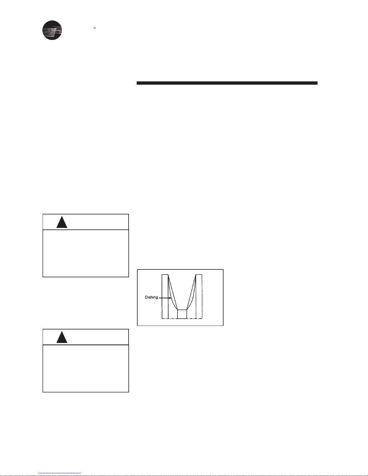
a) Worn groove sidewalls, "Dishing"
should not exceed 1/32"(0.8mm) for
individual belts. With a banded belt,
dishing should not exceed 1/
64"(0.4mm). When a banded belt
rides too low in worn pulley
grooves the tie band can be cut by
the flanges between the grooves.
b) Shiny pulley groove bottoms. This
is a sure sign that the belt has
bottomed out. The resulting
slippage shortens belt life.
c) Wobbling and/or damaged pulleys.
Generally caused by improper
pulley or bushing installation,
wobbling and/or damaged pulleys
can unbalance a drive, wear out
belt rapidly, and damage bearings
and bend shafts.
Check and repair worn bearings and
bent shafts.
4. Select replacement belts.
Replace all belts on a drive with a new
matched set.
a) Do not mix old and new belts on a
drive. A new belt will ride higher in
the pulley groove and operate at a
higher tension than an old belt.
Running them together will
damaged the new belt as it cannot
carry its share of the load.
b) Do not mix belt from different make,
because dimensions and
constructions will vary running such
"Mis-Matched" belts will not give full
service life.
c) Replace with correct type and cross
section belt. Matched SPA section
belt with SPA section pulleys. Do not
put a SPA belt section on a SPB
section pulley. Also dimensionally
similar belts can have very different
horsepower rating.
5. lnstall new belts
• Loosen the drive take up and place
the new belts on the pulley. Press
the belts with your hand to position
the slack of each belt on the same
side of the drive. lf the slack is on
different sides. start up loads can
break belt tensile cords.
• Do not pry or force belts onto the
pulleys. This can break the load
carrying tensile cords of the belt
Never use steam or hot water to
clean a refrigerant coil. Dangerous
pressures may be built up by
improper application of heat
resulting in equipment damage oe
personal injury.
WARNING
!
Failure to properly drain and vent
coils when not in use during freezing
temperatures may result in coil
freeze-up damage. Drain and vent
hardware provided by installing
contractor.
CAUTIONS
!
TRANE
R
and the belts will break or turn over
shortly after installation.
• Take up sleck until belts fit snugly.
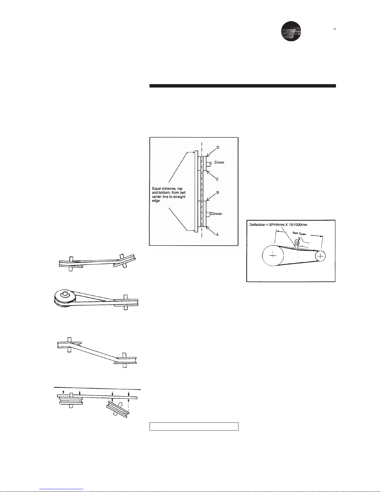
6. Check pulley alignment.
• Place a straight edge across
pulleys faces to correct alignment.
• Check parallel position of shafts
and correct alignment or grooves.
• Note: Mount pulleys as close to
bearing as possible.
31
Figure 16
Sheave Alignment
Fan Belt Tension
Note: Fan belt tension should be
checked at least twice during the first
day of operation, since there is a rapid
decrease in tension until belts are run
in.
Proper belt tensioning is required to
ensure maximum bearing and drive
component life and is based on fan
brake horsepower requirement.
Belt Tension Measurement
Check the belt tension as follows:
Measure the span length mm of the
drive. With a belt tensioner at the
center of the span. apply a force K
(perpendicular to the span) large
enough to deflect the belt 15mm per 1
meter of span. Refer to figure 17.
The deflection force for the belt should
be within the minimum and maximum
force shown in the Table 3. When the
tension drops to the minimum value,
readjust to the maximum value.
To measure belt tension, use a belt
tensioner as shown in Figure 18.
Determine actual deflection by
depressing one belt with the belt
tensioner and measuring the
deflection relative to the other belts or
to belt line. Adjust the belt tension to
the correct force (Newton) and tighten
all setscrews to the proper torques.
Figure 17
Belt Tension Measurement
Maintenance
Note: Store belts in a cool, dry place
out of direct sunlight.
Types of sheave and shaft misalignment
Horizonal Angular
Vertical Angular
Parrallel
Align with straightedge along
sheave faces
DEFLECTION = SPAN mm X 15/1000mm

TRANE
R
Maintenance
32
Figure 18
Belt Tension Measurement

TRANE
R
General
Use the tables in this section to assist in identifying the cause or causes of a malfunction in Air Handler operation. The
column header RECOMMENDED ACTION will suggest repair procedures.
Note: These tables are intended as a diagnostic aid only. For detailed repair procedures, contact your local Trane Service
Company.
Trouble Analysis
Loosen bearing setscrews and realign
Grease bearing(s) (Plummer block)
Retension belts
Apply grease
Clean surface of grease and purge
Correct alignment and check that shaft is level
Check across AC line. Correct voltage if
possible
Check line phases and terminal block
connection. Reduce system load, fan
driven speed or increase motor capacity
Remove fan cover, clean fan and replace
cover
Reduce load or replace with larger motor
Replace motor fan / clean
Check pulley alignment
Remove items used for transport only
Retension belts
Replace vibration isolator
Align drive
Tighten motor mounting bolts
Replace bearings and seals
Remove interference in motor fan housing
Remove item and repair
Replace bearings and seals
Retighten hub
Re-tension and align
Clean belts and pulleys; check for grease
leaks
Remove obstruction
Replace with full set
Change at advised dirty condition
Check unit running conditions
Replace with filter
sizes as supplied from Trane
Poor alignment
Inadequate lubrication
Overtensioned belts
No lubricant (plummer block type)
Overlubrication
Misaligned bearing
Low line voltage
Short circuit, phase to earth (open Phase)
Overloaded motor
Motor fan is clogged with dirt preventing
proper ventilation
Overloaded motor
Motor fan damaged
Poor pulley alignment
Transport brackets not removed
Overtensioned belts
Fan / unit vibration isolator collapsed
Misalign drive
Motor mounting bolts loose
Worn motor bearings
Fan rubbing on fan cover
Fan rubbing on inlet cone or guard
Worm fan bearings
Loose impeller
Incorrect tension or alignment
Dirt or grease on belts
Belts rubbing
Odd belts being fitted
Blocked with dirt
Air velocity too high
Filter wrong size
Bearing noise
Bearing is excessively hot
Motor stalls
Motor overheats
Excessive vibration
Excessive vibrator
Excessive motor noise
Excessive fan noise
Premature belt wear
Filter collapsing
Symptom Probable Cause Recommended Action
33

TRANE
R
34
Trouble Analysis
Repair or replace blade
Tighting lever fixings
Refit actuator correctly
Prevent bypass with block-off
Clean and unblock tubes
Check water pumps, valves and lines for
obstructions
Provide proper water temperature
Prevent bypassing with block-off
Clean and unblock tubes
Check fan-operating conditions
Check sensing bulb location and TXV operation
Check for blockage in distributor and tube
Repair damaged part
Check support and alignment of pipework and
rectify
Check frost protection method and correct, improve
Trapping of steaam supply
Resize / fit trap and check air break arrangement
Clean trap and refit
Clean drain line
Level unit
Design trap per unit installation instructions
Reduce fan speed
Design trap per unit installation instructions
Repair leaks
Insulate surfaces
Replace filters
Reduce filters bypass
See “Standing water” symptom
See “Wet interior insulation” section
Adjust tension
Replace belt or belt set. Check sheave alignment
Replace sheaves
Replace sheaves
Realign drive with MVP sheave set at mean pitch
diameter
Check for leaky bearings. Clean belts and sheaves
Adjust tension
Remove obstruction or realign drive for clearance
Check belt tension and overhung load
Replace sheave with larger one
Blade bent
Spindle or mechanism loose
Actuator loose
Air is by passing coil
Coil tubes are blocked
Incorrect airflow (CFM)
Incorrect water flow rate (GPM)
Incorrect water temperature
Air is by passing coil
Coil tubes are blocked
Incorrect airflow
Expansion valve not operating
Poor refrigerant distribution
Header / exposed pipe damage
Cracks in joints due to strain of pipework
on headers
Swelling of joints due to frost
(Water-hammer Steam Coils)
Incorrect hydraulic trapping
Blockage in trap
Plugged Drain Line
Unit not level
Improper trap design
Coil face velcity too high
Improper trap design
Drain pan leaks / overflows
Condensation on surfaces
Missing filters
Filter bypass
Standing water in drain pan
Moisture problems
Motor is poorly positioned
Worn or damaged belt
Worn Sheaves
Worn Sheaves
Misalign belt
Grease or oil on belts
Belt slipping
Belts rubbing
Excessive overhung load due to
overtensioned drive
Excessive overhung load due to a small
Damper seizing
Low coil capacity (Chilled Water)
Low coil capacity (Refrigerant)
Leaking Coil
Drain pan overflow
Standing water in drain pan
Wet interior insulation
Excess dirt in unit
Microbial growth (mold) inside
air handler
Loose fan belt
Short belt life
Rapid motor bearing wear
Symptom Probable Cause Recommended Action

TRANE
R
35
Trouble Analysis
Pulley and Belt

TRANE
R
36
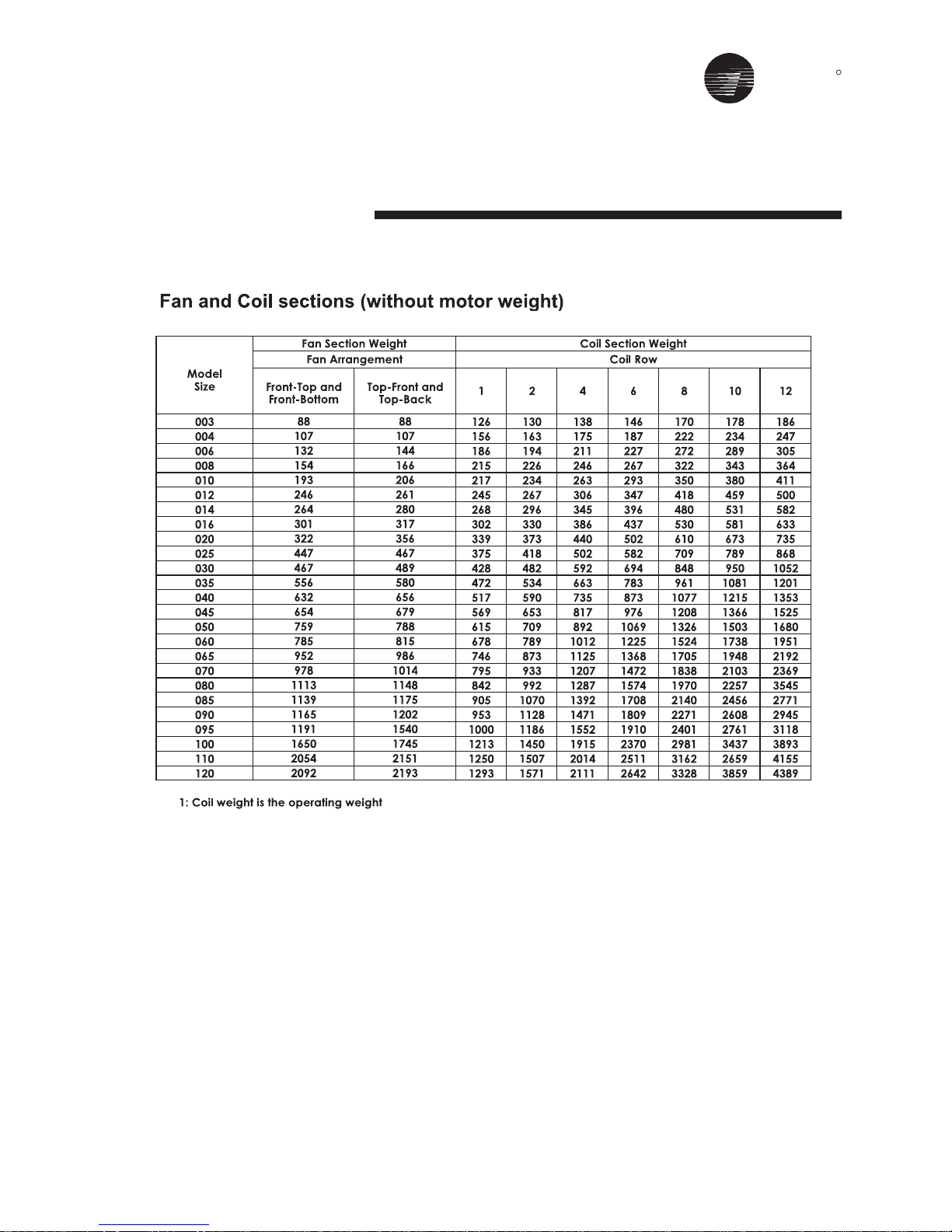
Appendix A
HDT - Unit Weight (CLCPEURO)
50mm Casing
HDT Unit Weight (kg) _ Fan and Coil Sections (without motor weight)
25mm Casing
1. Coil weight is the operating weight.

TRANE
R
Appendix A
HDT - Unit Weight (CLCPEURO)
37
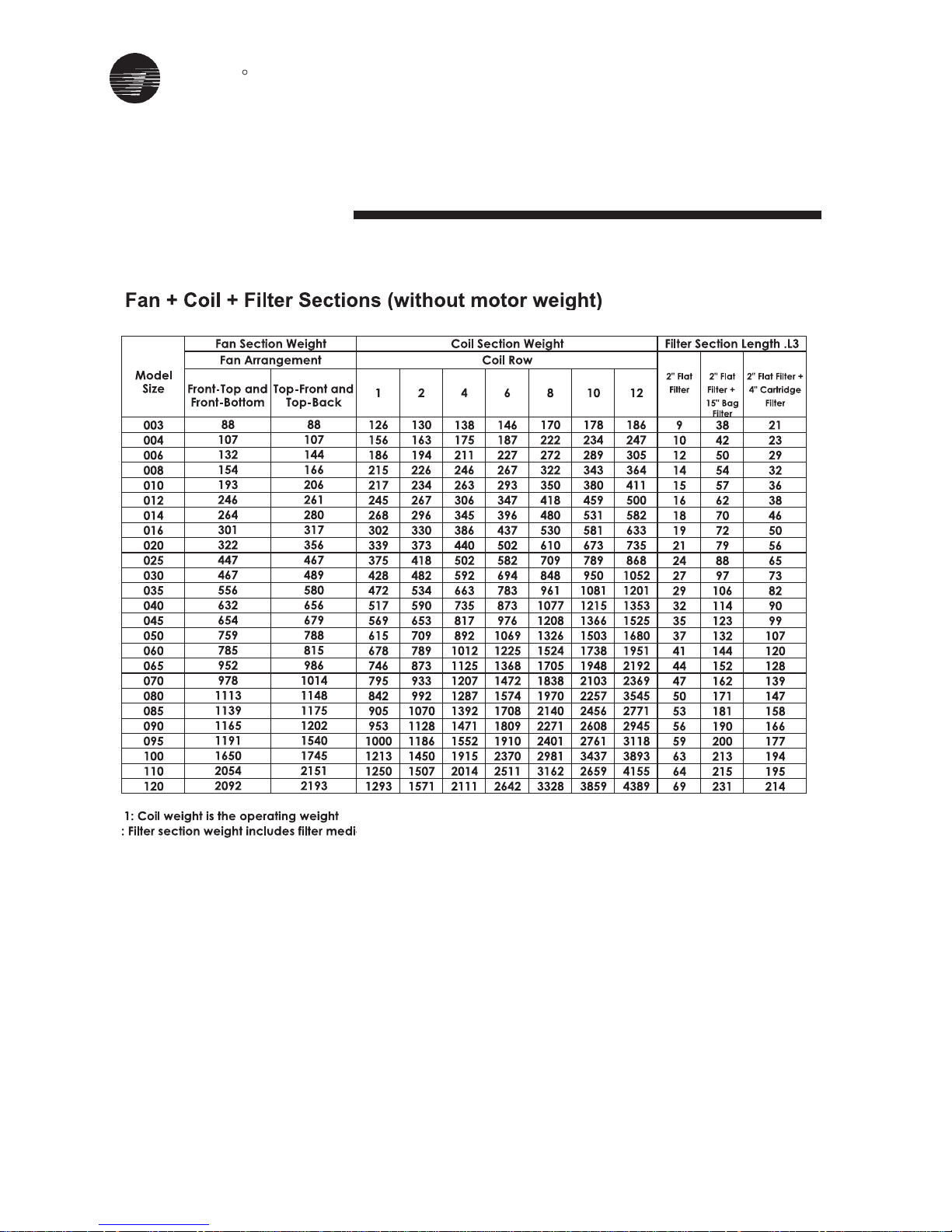
Fan + Coil + Filter Sections (without motor weight)
50mm Casing
25mm Casing
1. Coil weight is the operating weight.
2. Filter weight include filter media.

TRANE
R
Appendix A
HDT - Unit Weight (CLCPEuro)
38
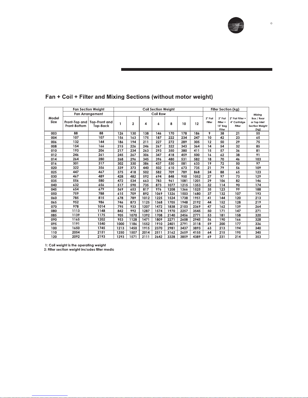
Fan + Coil + Filter and Mixing Sections (without motor weight)
50mm Casing
25mm Casing
Note:
1. Coil weight is the operating weight.
2. Filter weight includes filter media.

TRANE
R
Appendix A
VDT - Unit Weight (CLCPEuro)
39
Note:
1. Coil weight is the operating weight.
Fan and Coil Sections (without motor weight)
50mm Casing
25mm Casing

TRANE
R
Appendix A
VDT - Unit Weight (CLCPEuro)
40
50mm Casing
Fan + Coil + Filter Sections (without motor weight)
25mm Casing
Note:
1. Coil weight is the operating weight.
2. Filter weight includes filter media.
TRANE
R
Appendix B
HDT - Unit Weight (CLCPXP)
41
TRANE
R
Appendix B
HDT - Unit Weight (CLCPXP)
42
TRANE
R
Appendix B
HDT - Unit Weight (CLCPXP)
43

TRANE
R
Appendix B
VDT - Unit Weight (CLCPXP)
44
TRANE
R
Appendix B
VDT - Unit Weight (CLCPXP)
Fan + Coil + Filter Sections (without motor weight
)
tion Length .L3
Model
2" Flat 2" Flat 2" Flat Filter +
Size
Filter Filter + 4" Cartridge
15" Bag Filter
Filt
er
003
153 158
165 173
189 197 205
938 21
004
190 197 209 221 246 258 271
10 42 23
006
227 236 252 268 302 319 335
12 50 29
008
262 273 293 314 357 378 399
14 54 32
010
289 306 335 365 410 440 471
15 57 36
012
327 349 388 429 486 527 568
16 62 38
014
361 389 438 489 558 609 660
18 70 46
047886736955805254424610
19 72 50
328167896506345674244020
21 79 56
7101839858847866485145520
24 88 65
61
2141112101678477466016030
27 97 73
973195219311089068337966530
29 106 82
6451804107217801949408137040
32 114 90
437157517141702184
01488008540
35 123 99
722 746
755 780
540 561
638 662
378 412
510 531
313 329
350 366
229 242
288 302
162 174
190 202
103 103
132 132
Front-Top and Top-Front and
Front-Bottom Top-Back
6 8 10 12124
thgieWnoitceSlioCthgieWnoitceSnaF
woRlioCtnemegnarrAnaF
45

TRANE
R
Appendix CFans and Arrangement
Fan Size and Diamete
r
Fan Discharge Arrangements
Model Size Fan size
Fan size
Diameter (mm)
003
FC 200
200
BC 200
004
FC 225
225
BC 225
006
FC 250
250
BC 250
008
FC 280
280
BC 280
010
FC 315
315
BC 315
012
FC 400
400
BC 400
014
FC 400
400
BC 400
016
FC 450
450
BC 450
020
FC 500
500
BC 500
025
FC 560
560
BC 560
030
FC 560
560
BC 560
035
FC 630
630
BC 630
040
FC 710
710
BC 710
045
FC 710
710
BC 710
050
FC 800
800
BC 800
060
FC 800
800
BC 800
065
FC 900
900
BC 900
070
FC 900
900
BC 900
080
FC 1000
1000
BC 1000
085
FC 1000
1000
BC 1000
090
FC 1000
1000
BC 1000
095
FC 1000
1000
BC 1000
100
FC 1120
1120
BC 1120
110
BC 1250 1250
120
BC 1250 1250
46

TRANE
R
Appendix DFilter and Quantity
47
Filter Dimension (Nominal) and Arrangemen
t
Flat Filter, Bag Filter & Cartridge Filter
10

TRANE
R
Appendix DFilter and Quantity
48
Filter Dimension and Arrangement
High Capacity Filter - CLCP Euroonly

TRANE
R
Appendix DFilter and Quantity
49
Filter Dimension and Arrangement
Final Filter (HEPA)
TRANE
R
Appendix ETECO MOTOR Performance Data
380 / 415V - 50Hz, 2/4/6/8 Poles
50
Motor types AEEB and AEVB, Class F insulation, 380 / 415V - 50HZ, Eff 2.
Output
HP KW
Full
Load
Speed
(RPM)
Frame
Size
% Efficiency
Full
Load
3/4
Load
1/2
Load
Full
Load
3/4
Load
1/2
Load
% Power Factor Current (A) Current (A)
Full
Load
Full
Load
Locked
Rotor
Locked
Rotor
Full
Load
Locked
Rotor
PullUpPull
Out
2730
1345
920
710
2810
1395
925
710
2755
1405
915
695
2805
1405
940
700
2810
1415
940
690
2825
1400
930
705
2840
1425
950
705
2865
1435
955
715
2865
1440
955
720
2870
1445
950
720
2905
1445
960
720
2880
1450
975
720
2940
1455
970
730
63
63
71
80
71
71
80
90S
71
80
80
90L
80
80
90S
100L
80
90S
90
100L
90S
90L
100L
112M
90L
100L
112M
132S
100L
100L
132S
132M
112M
112M
132M
160M
112M
112M
132M
160M
132S
132S
132M
160M
132S
132M
160M
160L
160M
160M
160L
180L
61
64
61
52
75
71.5
66
64.5
75
71.5
68
70
78
76.5
74
68
80.5
76.5
75
74.5
81
78.5
76
75.5
83.5
81
81
81.5
85
83.5
85
82.5
86
85
83
84.5
86
86
85
84.5
87
86
84.5
85.5
88
88.5
88
86
89
89.5
89
89
57.5
63
56
46
74
70.5
63
61
75.5
71
67.5
70
78.5
76
71
66.5
81.5
76.5
73
74.5
81
78.5
76
75
84.5
81
81
81.5
8.55
83
85.5
81
86.5
84.5
82.5
84
87
86.5
85.5
83.5
86
86
84
85.5
88
89
87
86
89
90
89.5
89.5
50.5
57
48
37
69.5
65.5
57
53.5
73
64
62.5
65.5
75.5
72.5
66.5
61
80
69.5
68
71
79
75.5
70.5
71
83.5
78.5
78
79
84
80
84
77.5
86
83
81
81.5
86
84.5
84
80.5
83.5
84.5
82
83
86.5
87.5
84.5
84.5
87
89
88.5
88
77.5
68.5
64
47.5
85
70.5
67.5
60.5
86
74.5
72
70
88
77
71
66
887.5
79
68.5
67.5
88
81
75.5
67
89
82.5
76.5
74
89
82
81
67
91
82
78
71
90.5
82
80.5
74.5
88
82.5
77
75.5
89
86
79
76
89
86.5
84
78
69.5
58.5
54
41
77
61
56.5
48.5
78.5
65
60.5
59
81
66
60.5
56.5
81
68.5
57
59
82
72.5
65
59
84
75
63
63.5
83.5
73.5
75.5
58
88.5
77
71
62.5
87.5
76
74.5
64.5
85.5
75.5
70
65.5
87.5
81.5
71.5
65.5
85.5
82.5
80
70.5
58.5
45.5
43.5
34
65
48.5
45
39
66
51.5
48
47
68
52.5
48
45.5
70
55.5
44.5
47
70.5
59
52
46.5
74
62
50
50.5
74
61
64
45
82.5
65
59
50
79.5
64
62.5
51.5
79
63.5
58
53
82.5
71.5
59.5
53
77.5
74.5
71
58.5
0.60
0.64
0.72
1.15
0.88
1.12
1.27
1.45
1.32
1.59
1.74
1.74
1.65
1.92
2.16
2.52
2.41
2.82
3.31
3.39
3.18
3.56
3.95
4.48
4.58
5.09
5.71
5.64
6
6.62
6.59
8.2
7.24
8.13
8.75
9.45
8.01
8.84
9.11
9.91
11.1
12
13.1
13.2
14.5
14.9
16.3
17.4
21.5
22
22.7
24.5
2.7
2.6
2.5
3.5
5.9
5.7
5.5
5.5
8.7
8.7
8.2
7.9
10.9
10.9
10.9
9.8
17.5
16.4
16.4
15.3
22.9
21.8
21.8
19.7
34.9
32.8
32.8
31.7
43.7
49.1
43.7
43.7
61.1
63.2
57.9
55.8
61
61
60
60
83
83
83
83
104
104
104
104
156
156
156
156
0.55
0.59
0.66
1.05
0.81
1.03
1.16
1.33
1.21
1.46
1.59
1.59
1.51
1.76
1.98
2.31
2.21
2.58
3.03
3.10
2.91
3.26
3.62
4.10
4.19
4.66
5.23
5.16
5.49
6.06
6.03
7.51
6.63
7.44
8.01
8.65
7.33
8.09
8.34
9.07
10.2
11
12
12.1
13.3
13.6
14.9
15.9
19.7
20.1
20.8
22.4
2.5
2.4
2.3
3.2
5.4
5.2
5.0
5.0
8
8
7.5
7.2
10
10
10
9
16
15
15
14
21
20
20
18
32
30
30
29
40
45
40
40
56
58
53
51
56
56
55
55
76
76
76
76
95
95
95
95
143
143
143
143
0.066
0.135
0.197
0.256
0.129
0.260
0.392
0.511
0.198
0.387
0.595
0.783
0.259
0.517
0.772
1.037
0.387
0.769
1.158
1.578
0.514
1.037
1.561
2.059
0.767
1.528
2.292
3.089
1.013
2.023
3.040
4.061
1.258
2.502
3.773
5.004
1.391
2.763
4.202
5.545
1.874
3.767
5.671
7.561
2.520
5.006
7.445
10.081
3.703
7.483
11.225
14.915
335
220
260
360
320
275
220
190
300
260
230
170
240
265
200
185
270
210
230
205
260
220
200
185
245
240
200
215
310
300
200
265
290
250
210
200
290
240
190
200
205
240
250
200
215
260
265
200
215
235
240
220
335
215
245
350
270
240
215
185
260
245
215
140
230
250
185
165
250
190
215
180
240
195
190
150
245
210
185
200
280
275
190
245
265
210
175
180
265
220
175
180
185
200
230
180
190
220
225
190
180
190
210
195
340
240
280
370
310
270
240
265
280
280
230
205
270
270
240
230
280
250
270
220
270
255
230
240
290
270
250
250
320
340
270
310
330
310
280
270
325
310
260
270
260
280
310
270
260
300
300
270
285
280
280
260
0.002
0.002
0.007
0.010
0.002
0.005
0.009
0.017
0.002
0.007
0.012
0.023
0.005
0.009
0.017
0.033
0.006
0.014
0.023
0.046
0.010
0.017
0.033
0.065
0.014
0.033
0.058
0.138
0.023
0.046
0.125
0.180
0.042
0.065
0.151
0.343
0.042
0.085
0.151
0.344
0.063
0.103
0.217
0.484
0.076
0.143
0.400
0.588
0.147
0.297
0.588
1.233
9
9
12
20
12
12
20
23
12
20
20
27
20
20
23
37
20
23
27
37
23
27
37
45
27
37
45
68
87
37
68
77
44
43
65
107
45
45
77
128
68
68
77
127
68
77
128
151
128
128
151
206
9.5
9.5
13
18
13
13
18
24
13
18
18
27
18
18
24
37
18
24
27
37
24
27
37
47
27
37
47
70
37
37
70
80
47
45
68
115
47
47
80
120
70
70
80
135
70
80
120
148
120
120
148
205
0.180.25
0.37
0.5
0.55
0.75
1
0.75
1.5
1.1
2.2
3
3
4
3.7
5
7.5
5.5
7.5
10
15
11
1.5
2
5.5
4
380 Volts 415 Volts Kg-m %FLT %FLT %FLT Kgm² Kg Kg
Torque
Rotor
GD²
Approx
Weight
AEEB
Approx
Weight
AEVB
Voltage
Factor
200
2.08
220
1.89
346
1.2
365
1.13
400
1.04
420
0.99
440
0.94
500
0.83
550
0.75
Note :
1. For ampere values of other voltage motors, multiply the 415 volt values by the following factors:
2. FLT = fult-load torque
3. Data are subject to revisions without notice.

TRANE
R
51
Appendix ETECO MOTOR Performance Data
380 / 415V - 50Hz, 2/4/6/8 Poles
Motor types AEEB and AEVB, Class F insulation, 380 / 415V - 50HZ, Eff 2.
Voltage
Factor
200
2.08
220
1.89
346
1.2
365
1.13
400
1.04
420
0.99
440
0.94
500
0.83
550
0.75
Note :
1. For ampere values of other voltage motors, multiply the 415 volt values by the following factors:
2. FLT = fult-load torque
3. Data are subject to revisions without notice.
Output
HP KW
Full
Load
Speed
(RPM)
Frame
Size
% Efficiency
Full
Load
3/4
Load
1/2
Load
Full
Load
3/4
Load
1/2
Load
% Power Factor Current (A) Current (A)
Full
Load
Full
Load
Locked
Rotor
Locked
Rotor
Full
Load
Locked
Rotor
PullUpPull
Out
2925
1465
970
730
2930
1450
970
730
2930
1460
975
730
2960
1470
980
730
2950
1470
980
730
2950
1470
980
725
2960
1480
970
730
2950
1480
975
730
2950
1475
975
730
2955
1480
975
2955
1480
975
2960
1480
2960
1480
1520
18.5
25
22
30
40
30
50
37
55
75
75
100
90
125
175
132
150
200
250
185
45
60
150
110
380 Volts 415 Volts Kg-m %FLT %FLT %FLT Kgm² Kg Kg
Torque
Rotor
GD²
Approx
Weight
AEEB
Approx
Weight
AEVB
160M
160L
180L
200L
160L
180M
200L
225S
180M
180L
200L
225M
200L
200L
225M
250S
200L
225S
250S
250M
225M
225M
250M
280SC
250S
250S
280SC
280MC
250M
250M
280MC
315SC
280SA
280SC
315SC
315MC
280MA
280MC
315MC
315SA
315SC
315MC
315MA
315MC
315MA
315MB
90.5
90.5
90
89.5
91.5
91
91
90
92
91.5
92.5
91
92
92.5
91.5
90.5
92.5
92.5
92.5
91
93
92.5
92.5
92
93.5
93.5
93
92.4
94
94.5
93.6
93
94
94
93.9
93
94
94.5
94.1
94.6
94.8
94.3
94.8
94.9
94.9
95
91
90.5
90.5
89
91.5
91
91
90
92.5
91.5
92.5
90.5
91.5
93
91.5
90
92.5
92
92.5
91
92.5
93
92.5
91
93.5
93.5
92.8
92
94
94.5
93.5
92.4
93.9
93.9
93.8
93
94
94.5
94
94.5
94.8
94.2
94.6
94.9
94.8
94.9
90
89
90
87.5
91
90.5
91
89
91.5
90.5
92
89
89
92.5
88.5
88.5
91.5
91
91.5
89.5
91
92
91.5
90.2
87.5
92
91.6
91
93
93.5
91.6
91
91
91
91.6
91.7
91
91
92
90.8
91.2
92.4
92
91.3
92
92
91
86
85
77
92
86
83.5
78
90
86.5
83.5
77
84.5
86.5
81.5
78.5
88.5
85
85.5
79.5
91.5
85.5
84.5
80
9.05
89
83
80
90
88.5
84.5
80
88.5
86.5
84.5
80
88.5
86.5
84.5
89.2
87.5
84.5
89.2
87.5
89.2
87.5
90
80.5
82.5
70.5
90
83.5
82
72
88.5
82.5
79.5
70.5
79
83.5
75
70.5
87
81.5
81
73
90
83
79
74
88
87
79
74
89.5
87
80.5
75.5
86.5
83
80.5
75.5
86.5
84.5
80.5
87.5
84.5
80.5
87.5
84.5
87.5
84.5
85.5
71
76
59.5
85.5
76.5
76
62
83.5
74.5
71.5
59
71
76.5
65
60
81
74.5
73
62
86
76.5
69.5
66
85.5
81
73
66
86
83
73
68
84.5
79
73
68
84.5
79
73
84.5
80.5
73
84.5
80.5
84.5
80.5
27.5
29.2
29.6
32.9
33.6
36.3
37.2
40.4
41.1
42.9
44
48.5
58.3
56.7
60.8
63.8
69.2
72.1
71.6
78.6
79.9
85.9
87
92.8
100
102
108
112
134
135
144
153
164
168
171
183
201
204
211
237
242
252
270
274
333
339
209
213
208
208
251
246
246
246
295
295
295
295
404
410
394
393
494
494
486
481
557
557
573
552
721
683
683
677
934
934
928
928
1119
1119
1114
1114
1365
1365
1365
1562
1562
1562
1775
1775
2190
2190
25.2
26.7
27.1
30.1
30.8
33.2
34.1
37
37.6
39.3
40.3
44.4
53.4
51.9
55.7
58.4
63.4
66
65.6
71.7
73.2
78.7
79.7
85
92
93.5
99
103
123
124
132
140
150
154
157
168
184
187
193
217
222
231
247
251
305
310
191
195
190
190
230
225
225
225
270
270
270
270
370
375
361
360
452
452
445
440
510
510
525
505
660
625
625
620
855
855
850
850
1025
1025
1020
1020
1250
1250
1250
1430
1430
1430
1625
1625
2005
2005
4.963
9.909
14.966
19.887
6.193
12.515
18.708
24.858
7.432
14.915
22.334
29.830
9.809
19.751
29.627
39.773
12.303
24.689
37.034
49.716
14.763
29.627
44.440
60.5
18.392
36.783
55.2
73.4
24.605
49.044
74.9
100
29.7
59.4
89.9
120
36.3
72.4
110
43.5
86.9
132
49.4
98.7
60.9
122
215
240
200
200
250
200
205
185
220
215
220
200
190
240
220
200
180
200
210
200
145
190
230
140
165
200
145
135
150
240
140
135
130
145
140
125
120
125
120
110
125
120
105
110
105
110
180
195
155
180
190
170
170
150
190
180
200
175
170
195
190
170
145
175
190
170
130
160
210
110
140
165
115
105
120
200
110
105
105
115
110
100
95
100
95
90
100
95
85
90
85
90
270
285
230
240
290
230
215
200
270
260
250
220
280
285
240
230
260
230
240
230
260
215
270
210
315
265
220
210
285
280
210
210
220
220
210
210
210
210
210
210
210
210
210
210
210
210
0.183
0.381
1.233
1.610
0.237
0.571
1.610
2.093
0.283
0.744
1.919
2.442
0.521
1.264
2.326
3.475
0.633
1.649
3.373
4.572
1.074
1.731
3.829
8.4
1.410
3.643
7
10
1.678
4.490
10
19.1
2.7
7
15.7
23.9
3.6
8.7
17
6.3
11.3
18.9
7.2
14.3
7.3
14.3
128
151
206
293
151
183
293
346
190
206
293
370
289
293
370
498
289
346
498
562
353
370
562
650
466
498
600
680
517
562
690
840
620
630
870
1020
690
710
970
840
890
1100
910
970
1000
1070
120
148
205
280
148
175
280
330
190
205
280
360
285
280
360
450
285
330
450
520
370
360
520
710
470
450
670
740
545
520
790
920
660
720
950
1120
760
780
1100
930
1020
1210
1000
1070
1100
1180
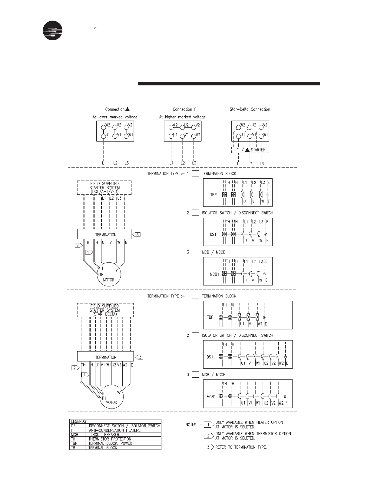
TRANE
R
52
Typical - unit wiring diagram
CONNECTION DRAWING
FOR BARE MOTOR
CONNECTION DRAWING
FOR TERMINATION - 3 POLE
CONNECTION DRAWING
FOR TERMINATION - 6 POLE

TRANE
R
Typical - Wiring Diagram
Starter, Star-Delta
380 - 420V, 3Phase, 4Wires, + ELCB Standard
53

TRANE
R
54
Typical - Wiring Diagram
Starter, Dol
380 - 420V, 3Phase, 4Wires, + ELCB Standard

TRANE
R
55
Typical - Wiring Diagram
Starter, Dol
380 - 420V, 3Phase, 4Wires, Standard
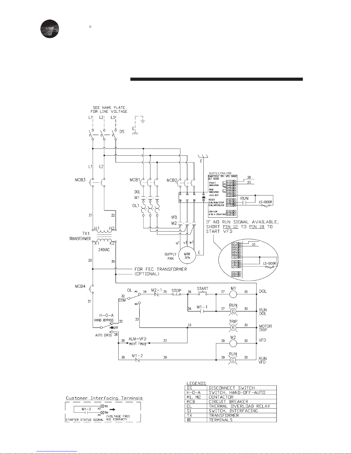
TRANE
R
56
Typical - Wiring Diagram
VFD Starter + Dol
Bypass Starter C/W Door Switch
380/415/440/460V, 3Phase, 3Wires

TRANE
R
57
Typical - Wiring Diagram
Starter, Dol
380 - 420V, 3Phase, 4Wires + ELCB
Enhance with Thermistor Relay

TRANE
R
58
Typical - Wiring Diagram
Starter, Dol
380 - 420V, 3Phase, 4Wires, Standard

TRANE
R
59
Typical - Wiring Diagram
Starter, Dol
380 - 420V, 3Phase, 4Wires,
Enhance with Thermistor Relay

TRANE
R
60
Typical - Wiring Diagram
Starter, Star-Delta
380 - 420V, 3Phase, 4Wires,
Enhance with Thermistor Relay

TRANE
R
61
Typical - Wiring Diagram
Starter, Star-Delta
380 - 420V, 3Phase, 4Wires, Standard

TRANE
R
Safety Recommendations
To avoid accidents and damage, the
following recommendations should be
observed during maintenance and
service visits:
1. Disconnect the main supply before
any servicing on the unit.
2. Service work on the refrigeration
system and the electrical system
should be carride out only by
qualified and experienced
personnel.
Maintenance Contract
lt is strongly recommended that you
sign a maintenance contract with your
local Service Agency. This contract
provides regular maintenance of your
installation by a specialist in our
equipment. Regular maintenance
ensures that any malfunction is
detected and corrected in good time
and minimizes the possibility that
serious damage will occur. Finally,
regular maintenance ensures the
maximum operating life of your
equipment. We would remind you that
failure to respect these installation and
maintenance instructions may result
in immediate cancellation of the
warranty.
The manufacturer has a policy of
continuous product improvement, and
reserves the right to alter any details of
the products at any time without notice.
This publication is a general guide to
install, use and properly maintain our
products. The information given may
be different from the specification for a
particular country or for a specific order.
ln this event. Please refer to your
nearest office.
ln no event shall Trane be liable for
any incldental or consequential
damages resulting from the use,
misuse or inability to use the product.
Training
The equipment described in this
manual is the result of many years
of research and continuous
development. To assist you in
obtaining the best use of it and
maintaining it in perfect operating
condition over a long period of time,
the manufacturer has at your
disposal a refrigeration and air
conditioning service school. The
principal aim of this is to give
operators and technicians a better
knowledge of the equipment they
are using, or that is under their
charge. Emphasis is particularly
give to the importance of periodic
checks on the unit operating
parameters as well as on preventive
maintenance. which reduces the
cost of owning the unit by avoiding
serious and costly breakdown.
For additional information, contact:
Distirbutor / Installer stamp
62

TRANE
R
TRANE AHU Pre-start up Checklist
General Information
Date
Project Name:
Trane Sales Order #
Trane AHU Model
Unit Serial No.:
Unit TAG #
Design Capacity (CFM) @ Design ESP
AHU Location
Area Served
Start-Up Contractor
T & C Technician / Engineer
Casing Installation Check
Exterior casing in good condition
Interior casing in good condition
Is the unit installation level?
Are the unit clearances adequate for service and operation?
Do all access doors open freely and are the handles operational?
Fan-Motor Installation Checks
Have all shipping braces / brackets been removed?
Fan and Motor Alignment correct
Belt tension & condition good
Belt guard in place and secure.
Do the fan rotates freely?
Electrical Installation Checks
Electrical Cable entry at unit wall & motor terminal box is sealed.
Have all electrical connections been tested for tightness?
Insulation test done on motor winding.
Has overcurrent protection been installed to match unit nameplate
requirement?
Does the electical supply correspond to the unit nameplate?
External Power Disconnects in place and labeled.
Proper grounding Installed for motor and unit.
Motor Nameplate FLA
Installed Motor kW
Electrical Power Supply
Voltage Imbalance
Supply Fan
Amp
kW
Vac/Ph/Hz
%
Return / Exhaust Fan
Amp
kW
Vac/Ph/Hz
%
63
Pre-Start Up Checklist
ohm
ohm

TRANE
R
64
TRANE
R
65
Coil & Piping Installation Checks
Coils water In/OUT piping connected correctly.
Condensate drain and P-trap been installed correctly / primed
External pipe fittings complete and pipes properly supported
Coil Headers of specified material
Valves installed in correct direction
Filter Instalation Checks
Are the air filters installed with proper orientation?
Filter Diffrential Pressure Switch operation?
Mixing Box / Economizer Dampers
Outdoor Air Damper Operation check
Return Air Damper Operation check
Exhaust Air Damper Operation check
Have the air dampers been inspected?
Supply Duct Installation Checks
3D requirement
Duct visibly sound, clean, sealed & in good condition
Ducts have no apprarent flow restriction.
Ducts have turning vanes in square elbows
Notes:
Put a check or an “X” in the box if the indicated item is “OK”
Put “NA” in the box if the item does not apply.
Put “BO” in the box if the work is was performed by Others
(include appropriate explanation)
Pre-Start Up Checklist

TRANE
R
66

TRANE
R

TRANE
R
Literature Order Number
File Number
Supersedes
Stocking Location
Trane has a policy of continuous product and product data improvement and reserves the right to
change design and specifications without notice. Only qualified technicians should perform the installation and servicing of equipment referred to in this publication.
TRANE
Trane
www.trane.com
IND-SVN01A-E4 (January 2010)
IND-SVN01A-E4 (December 2006)
MALAYSIA
R
For more information, contact your local
district office
 Loading...