

Page 1

TL-WR541G
54M Wireless Router
- I -
Rev: 1.0.3
1910010061
Page 2

COPYRIGHT & TRADEMARKS
Specifications are subject to change without notice. is a registered trademark of
TP-LINK TECHNOLOGIES CO., LTD. Other brands and product names are trademarks or
registered trademarks of their respective holders.
No part of the specifications may be reproduced in any form or by any means or used to make any
derivative such as translation, transformation, or adaptation without permission from TP-LINK
TECHNOLOGIES CO., LTD. Copyright © 2008 TP-LINK TECHNOLOGIES CO., LTD. All rights
reserved.
FCC STATEMENT
This equipment has been tested and found to comply with the limits for a Class B digital device,
pursuant to part 15 of the FCC Rules. These limits are designed to provide reasonable protection
against harmful interference in a residential installation. This equipment generates, uses and can
radiate radio frequency energy and, if not installed and used in accordance with the instructions,
may cause harmful interference to radio communications. However, there is no guarantee that
interference will not occur in a particular installation. If this equipment does cause harmful
interference to radio or television reception, which can be determined by turning the equipment off
and on, the user is encouraged to try to correct the interference by one or more of the following
measures:
• Reorient or relocate the receiving antenna.
• Increase the separation between the equipment and receiver.
• Connect the equipment into an outlet on a circuit different from that to which the receiver is
connected.
• Consult the dealer or an experienced radio/ TV technician for help.
This device complies with part 15 of the FCC Rules. Operation is subject to the following two
conditions:
1) This device may not cause harmful interference.
2) This device must accept any interference received, including interference that may cause
undesired operation.
FCC RF Radiation Exposure Statement
This equipment complies with FCC RF radiation exposure limits set forth for an uncontrolled
environment. This device and its antenna must not be co-located or operating in conjunction with
any other antenna or transmitter.
“To comply with FCC RF exposure compliance requirements, this grant is applicable to only
- II -
Page 3

Mobile Configurations. The antennas used for this transmitter must be installed to provide a
separation distance of at least 20 cm from all persons and must not be co-located or operating in
conjunction with any other antenna or transmitter.”
CE Mark Warning
This is a class B product. In a domestic environment, this product may cause radio interference, in
which case the user may be required to take adequate measures.
National Restrictions
2400.0-2483.5 MHz
Country Restriction Reason/remark
Bulgaria
France
Italy
Luxembourg None
Norway Implemented
Russian Federation Only for indoor applications
General authorization required for outdoor use and
public service
Outdoor use limited to 10
mW e.i.r.p. within the band
2454-2483.5 MHz
If used outside of own premises, general authorization is
Military Radiolocation use. Refarming of the 2.4 GHz
band has been ongoing in recent years to allow current
relaxed regulation. Full implementation planned 2012
required
General authorization required for network and service
supply(not for spectrum)
This subsection does not apply for the geographical area
within a radius of 20 km from the centre of Ny-Ålesund
Note: It’s not used outdoors in France.
- III -
Page 4

- IV -
Page 5

Package contents
The following contents should be found in your box:
¾ One TL-WR541G 54Mbps Wireless Router
¾ One AC power Adapter for TL-WR541G 54Mbps Wireless Router
¾ One Quick Installation Guide
¾ One Resource CD for TL-WR541G 54Mbps Wireless Router, including:
• This Guide
• Other Helpful Information
Note:
)
Make sure that the package contains the above items. If any of the listed items are damaged or
missing, please contact with your distributor.
Conventions
The router or TL-WR541G mentioned in this guide stands for TL-WR541G 54Mbps Wireless
Router without any explanation.
- V -
Page 6

CONTENTS
Chapter 1. Introduction ........................................................................................ 1
1.1 Ov
1.2 Features
1.3 Panel Layout................................................................................................................... 2
1.3.1 The Front Panel ....................................................................................................... 2
1.3.2 The Rear Panel
erview of the Router ................................................................................................... 1
.......................................................................................................................... 1
........................................................................................................ 4
Chapter 2. Connecting the Router....................................................................... 5
2.1 System Requirements
2.2 Inst
2.3 Connecting the Router
allation Environment Requirements........................................................................... 5
..................................................................................................... 5
.................................................................................................... 5
Chapter 3. Quick Installation Guide ....................................................................7
3.1 TCP/IP
3.2 Quick In
configuration....................................................................................................... 7
stallation Guide.................................................................................................. 9
Chapter 4. Configuring the Router .................................................................... 13
4.1 Login
4.2 S
4.3 Quick Setup
4.4 Network
4.4.1 LAN
4.4.2 W
4.4.3 MAC Clone
4.5 Wireless
4.5.1 Wireless Set
4.5.2 MAC Filtering
4.5.3 Wireless S
............................................................................................................................. 13
tatus............................................................................................................................ 13
.................................................................................................................. 14
......................................................................................................................... 15
........................................................................................................................ 15
AN ...................................................................................................................... 15
............................................................................................................ 26
........................................................................................................................ 27
tings ................................................................................................... 27
......................................................................................................... 32
tatistics.................................................................................................. 35
- VI -
Page 7

4.6 DHCP............................................................................................................................ 36
4.6.1 DHCP
4.6.2 DHCP
Settings....................................................................................................... 36
Clients List .................................................................................................. 37
4.6.3 Address Reserv
4.7 Forwarding
4.7.1 V
4.7.2 Port T
4.7.3 DMZ
4.7.4 UPnP
4.8 Security
4.8.1 Firewall
4.8.2 IP
.................................................................................................................... 39
irtual Servers ....................................................................................................... 39
riggering ....................................................................................................... 41
....................................................................................................................... 43
..................................................................................................................... 43
......................................................................................................................... 44
.................................................................................................................. 45
Address Filtering................................................................................................ 45
4.8.3 Domain Filtering
ation ............................................................................................. 37
..................................................................................................... 48
4.8.4 MAC Filtering
4.8.5 Remote Management
4.8.6 Adv
4.9 IP
anced Security................................................................................................. 52
& MAC Binding Setting ............................................................................................. 54
4.9.1 Binding Setting
4.9.2 ARP
4.10 S
tatic Routing................................................................................................................ 56
4.11 DDNS
List................................................................................................................. 56
............................................................................................................................ 58
4.11.1 Dyndns.org DDNS
4.11.2 Oray
.net DDNS ...................................................................................................... 59
......................................................................................................... 49
............................................................................................ 51
....................................................................................................... 54
................................................................................................. 58
4.11.3 Comexe.cn DDNS ................................................................................................. 59
4.12 Sy
stem Tools................................................................................................................. 60
4.12.1 T
4.12.2 Firmware
4.12.3 Factory
- VII -
ime....................................................................................................................... 61
................................................................................................................ 62
Defaults..................................................................................................... 63
Page 8

4.12.4 Backup and Restore .............................................................................................. 63
4.12.5 Reboot
4.12.6 Password
4.12.7 Log
4.12.8 S
................................................................................................................... 64
............................................................................................................... 64
......................................................................................................................... 65
tatistics................................................................................................................. 65
Appendix A: FAQ.................................................................................................... 68
Appendix B: Configuring the PC........................................................................... 73
Appendix C: Specifications................................................................................... 77
Appendix D: Glossary............................................................................................ 78
- VIII -
Page 9

TL-WR541G 54M Wireless Router User Guide
Chapter 1. Introduction
Thank you for choosing TL-WR541G 54Mbps Wireless Router.
1.1 Overview of the Router
The TL-WR541G 54Mbps Wireless Router integrates 4-port Switch, Firewall, NAT-router and
Wireless AP. Its design is dedicated to Small Office/Home Office (SOHO) wireless network solutions.
The TL-WR541G 54Mbps Wireless Router will allow you to connect your network wirelessly better
than ever, sharing Internet Access, files and fun, easily and securely.
In the most attentive wireless security, the TL-WR541G 54Mbps Wireless Router provides
multiple protection measures. It can be set to turn off wireless network name (SSID) broadcast so
that only stations that have the SSID can be connected. The router provides wireless LAN
64/128/152-bit WEP encryption security, and WPA/WPA2 and WPA-PSK/WPA2-PSK
authentication, as well as TKIP/AES encryption security. It also supports VPN pass-through for
sensitive data secure transmission.
The TL-WR541G 54Mbps Wireless Router complies with the IEEE 802.11g and IEEE 802.11b
™
standards so that the data transmission rate is up to 54Mbps. It adopts 2x to 3x eXtended Range
WLAN transmission technology so that transmission distance is 2-3 times of traditional IEEE
802.11g and IEEE 802.11b solutions, up to a distance of 855.36m tested in China. Transmission
range is extended to 4-9 times. It is compatible with all IEEE 802.11g and IEEE 802.11b products.
The TL-WR541G 54Mbps Wireless Router provides flexible access control so that parents or network
administrators can establish restricted access policies for children or staff. It has built-in NAT and
DHCP server supporting static IP address distributing. It also supports Virtual Server and DMZ host for
Port Triggering needs, and remote management and log so that network administrators can manage
and monitor the network in real time. This device supports Bridge mode which can make two APs
communicate with each other wirelessly.
The TL-WR541G 54Mbps Wireless Router is easy-to-manage. Quick Setup is supported and
friendly help messages are provided for every step. So you can configure it quickly and share
Internet access, files and fun.
1.2 Features
¾ Complies with IEEE 802.11g, IEEE 802.11b, IEEE 802.3, IEEE 802.3u standards.
¾ 1 10/100M Auto-Negotiation RJ45 WAN port, 4 10/100M Auto-Negotiation RJ45 LAN ports,
- 1 -
Page 10

TL-WR541G 54M Wireless Router User Guide
supporting Auto MDI/MDIX.
¾ Adopts 2x to 3x eXtended Range™ wireless LAN transmission technology.
¾ Supports 54/48/36/24/18/12/9/6Mbps or 11/5.5/3/2/1Mbps data transfer rates.
¾ Provides WPA/WPA2, WPA-PSK/WPA2-PSK authentication, TKIP/AES encryption security.
¾ Shares data and Internet access for users, supporting PPPoE, Dynamic IP, Static IP, L2TP,
PPTP, BigPond Cable Internet access.
¾ Supports Virtual Server, Special Application and DMZ host.
¾ Supports UPnP, Dynamic DNS, Static Routing, VPN Pass-through.
¾ Connecting Internet on demand and disconnecting from the Internet when idle for PPPoE.
¾ Built-in NAT and DHCP server supporting static IP address distributing.
¾ Built-in firewall supporting IP address filtering, Domain Name filtering, and MAC address
filtering.
¾ Supports connecting/disconnecting from the Internet on a specified time of day.
¾ Supports access control, parents and network administrators can establish restricted access
policies based on time of day for children or staff.
¾ Provides 64/128/152-bit WEP encryption security and wireless LAN ACL (Access Control
List).
¾ Supports Flow Statistics.
¾ Supports ICMP-FLOOD, UDP-FLOOD, and TCP-SYN-FLOOD filter.
¾ Ignores Ping packets from WAN or LAN ports.
¾ Supports firmware upgrade.
¾ Supports Web management.
1.3 Panel Layout
1.3.1 The Front Panel
The Router’s LEDs are located on the front panel (View from left to right).
- 2 -
Page 11

TL-WR541G 54M Wireless Router User Guide
Figure 1-1 Front Panel sketch
Name Status Indication
Off Power off
PWR
On Power on
On The router is initializing or maybe has a system error.
SYS
Flashing The router is working properly
Off The router has a hardware error
Off There is no wireless device linked to the router
WLAN
Flashing The Wireless function is enabled
Off There is no device linked to the corresponding port
WAN,1-4
On
activity
Flashing There is an active device linked to the corresponding port
Table 2-1 The LEDs description
- 3 -
There is a device linked to the corresponding port but no
Page 12

TL-WR541G 54M Wireless Router User Guide
1.3.2 The Rear Panel
The following parts are located on the rear panel (View from left to right).
¾ AC power socket:
¾ LAN 1,2,3,4:
¾ WAN:
¾ Reset button:
There are two ways to reset the router's factory defaults:
1) Use the Factory Defaults function on System Tools -> Factory Defaults page in the
router's Web-based Utility.
2) Use the Factory Default Reset button: First, turn off the router's power. Second, press
and hold the default reset button then turn on the router's power, until the SYS LED lights
up (about 3 seconds). Last, release the reset button and wait for the router to reboot.
Please use the power adapter which is supplied with the TL-WR541G
54Mbps Wireless Router only, the use of a different adapter may result
in product damage.
Four 10/100Mbps RJ45 LAN ports for connecting the router to the local
PC(s)
This WAN port is where you will connect the cable/DSL Modem, or
Ethernet
Note:
)
¾ Wireless antenna
Ensure the router is powered on before it restarts completely.
Figure 1-2 Rear Panel sketch
- 4 -
Page 13

TL-WR541G 54M Wireless Router User Guide
Chapter 2. Connecting the Router
2.1 System Requirements
¾ Broadband Internet Access Service (DSL/Cable/Ethernet)
¾ One DSL/Cable Modem that has an RJ45 connector (you do not need it if you connect the
router to the Ethernet)
¾ Each PC in the LAN needs a working Ethernet Adapter and an Ethernet cable with RJ45
connectors
¾ TCP/IP protocol must be installed on each PC
¾ Web browser, such as Microsoft Internet Explorer 5.0 or later, Netscape Navigator 6.0 or later
2.2 Installation Environment Requirements
¾ Do not place in direct sunlight or near a heater or heating vent
¾ Do not cluttered or crowded. There should be at least 2 inches (5 cm) of clear space on all
sides of the router
¾ Well ventilated (especially if it is in a closet)
¾ Operating temperature: 0 ~40 (32 ~104 )℃℃℉ ℉
¾ Operating Humidity: 10%~90%RH, Non-condensing
2.3 Connecting the Router
Before you install the router, you should connect your PC to the Internet through your broadband
service successfully. If there is any problem, please contact your ISP. After that, please install the
router according to the following steps. Don't forget to pull out the power plug and keep your
hands dry.
1. Power off your PC, Cable/DSL Modem, and the router.
2. Locate an optimum location for the router. The best place is usually near the center of the
area in which your PC will connect wirelessly. The place must accord with the Installation
Environment Requirements.
3. Adjust the direction of the antenna. Normally, upright is a good direction.
4. Connect the PC(s) and each Switch/Hub in your LAN to the LAN Ports on the router, shown in
Figure 2-1. (If you have the wireless NIC and want to use wirele
- 5 -
ss function, you can skip this
Page 14

TL-WR541G 54M Wireless Router User Guide
step.)
5. Connect the DSL/Cable Modem to the WAN port on the router, shown in Figure 2-1.
6.
Connect the AC power adapter to the AC power socket on the router, and the other end into
an electrical outlet. The router will start to work automatically.
7. Power on your PC and Cable/DSL Modem.
Figure 2-1 Hardware Installation of the TL-WR541G 54Mbps Wireless Router
- 6 -
Page 15

TL-WR541G 54M Wireless Router User Guide
Chapter 3. Quick Installation Guide
After connecting the TL-WR541G Router into your network, you should configure it. This chapter
describes how to configure the basic functions of your TL-WR541G Wireless Router. These
procedures only take you a few minutes. You can access the Internet via the router immediately
after successfully configuring.
3.1 TCP/IP configuration
The default IP address of the TL-WR541G 54Mbps Wireless Router is 192.168.1.1. And the
default Subnet Mask is 255.255.255.0. These values can be seen from the LAN. They can be
changed as you desire, as an example we use the default values for description in this guide.
Connect the local PC to the LAN ports of the router. There are then two ways to configure the IP
address for your PC.
¾ Configure the IP address manually
1) Set up the TCP/IP Protocol for your PC. If you need instructions as to how to do this,
please refer to Appendix B: "Configuring the PC."
2) Configure the network parameters. The IP address is 192.168.1.xxx ("xxx" is from 2 to
254), Subnet Mask is 255.255.255.0, and Gateway is 192.168.1.1 (The router's default
IP address)
¾ Obtain an IP address automatically
1) Set up the TCP/IP Protocol in "Obtain an IP address automatically" mode on your PC.
If you need instructions as to how to do this, please refer to Appendix B: "Configuring the
PC."
2) Power off the router and PC. Then turn on the router and restart the PC. The built-in
DHCP server will assign IP address for the PC.
)
Note:
For Windows 98 OS or earlier, the PC and router may need to be restarted.
Now, you can run the Ping command in the command prompt to verify the network connection
between your PC and the router. The following example is in Windows 2000 OS.
Open a command prompt, and type ping 192.168.1.1, and then press Enter.
If the result displayed is similar to that shown in Figure 3-1, the connection between your
the router has been established.
- 7 -
PC and
Page 16
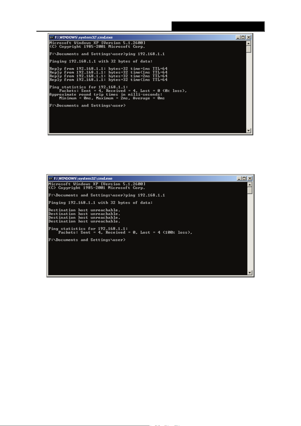
Figure 3-1 Success result of Ping command
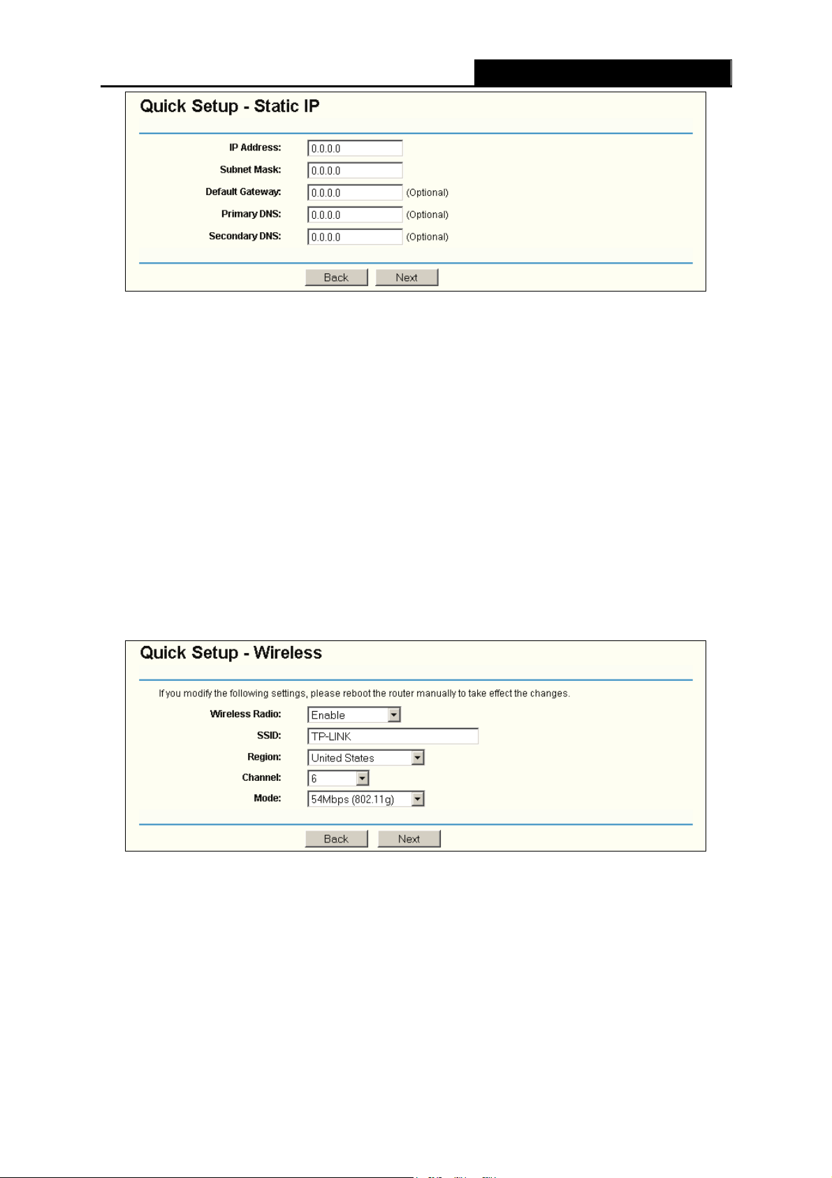
If the result displayed is similar to that shown in Figure 3-2, it means that your PC has not
connected to the router.
TL-WR541G 54M Wireless Router User Guide
Figure 3-2 Failure result of Ping command
Please check the connection following these steps:
1. Is the connection between your PC and the router correct?
Note:
)
The 1/2/3/4 LEDs of LAN port which you link to on the router and LEDs on your PC's adapter
should be lit.
2. Is the TCP/IP configuration for your PC correct?
Note:
)
- 8 -
Page 17

If the router's IP address is 192.168.1.1, your PC's IP address must be within the range of
192.168.1.2 ~ 192.168.1.254, the gateway must be 192.168.1.1
TL-WR541G 54M Wireless Router User Guide
3.2 Quick Installation Guide
With a Web-based (Internet Explorer or Netscape® Navigator) utility, it is easy to configure and
manage the TL-WR541G 54Mbps Wireless Router. The Web-based utility can be used on any
Windows, Macintosh or UNIX OS with a Web browser.
Connect to the router by typing http://192.168.1.1 in the address field of Web browser.
Figure 3-3 Login the router
After a moment, a login window will appear similar to that shown in Figure 3-4. Enter admin for
the User Name and Password, both in lower case letters. Then click the OK button or press the
Enter key.
Figure 3-4 Login Windows
Note:
)
If the above screen does not pop-up, it means that your Web-browser has been set to a proxy. Go
to Tools menu>Internet Options>Connections>LAN Settings, in the screen that appears, cancel
the Using Proxy checkbox, and click OK to finish it.
If the User Name and Password are correct, you can configure the router using the Web browser.
Please click the Quick Setup link on the left of the main menu and the Quick Setup screen will
appear.
- 9 -
Page 18

Figure 3-5 Quick Setup
TL-WR541G 54M Wireless Router User Guide
Click Next, and then Choose WAN Connection Type page will appear, shown in Figure 3-6.
Figure 3-6 Choose WAN Connection Type
The router supports three popular ways to connect to Internet. Please select one compatible with
your ISP. Click Next to enter the necessary network parameters.
If you choose "PPPoE", you will see this page shown in Figure 3-7:
Figure 3-7 Quick Setup - PPPoE
¾ Account Name and Password - Enter the Account Name and Password provided by your
ISP. These fields are case sensitive. If you have difficulty with this process, please contact
your ISP.
If you choose "Dynamic IP", the router will automatically receive the IP parameters from your ISP
without needing to enter any parameters.
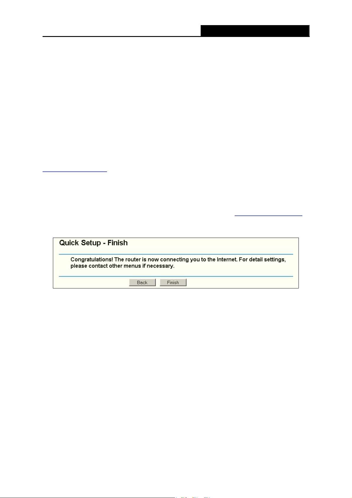
If you Choose "Static IP", the Static IP settings page will appear, shown in Figure 3-8:
- 10 -
Page 19
TL-WR541G 54M Wireless Router User Guide
Figure 3-8 Quick Setup - Static IP
Note - The IP parameters should have been provided by your ISP.
¾ IP Address - This is the WAN IP address as seen by external users on the Internet (including
your ISP). Enter the IP address into the field.
¾ Subnet Mask - The Subnet Mask is used for the WAN IP address, it is usually 255.255.255.0
¾ Default Gateway - Enter the gateway IP address into the box if required.
¾ Primary DNS - Enter the DNS Server IP address into the boxes if required.
¾ Secondary DNS - If your ISP provides another DNS server, enter it into this field.
After you complete the above, click Next, the Wireless settings page will appear, shown in Figure
3-9.
Figure 3-9 Quick Setup - Wireless settings
In this page, you can configure the following wireless parameters:
¾ Wireless Radio - Indicates whether the Access Point feature of the router is enabled or
disabled. If disabled, the WLAN LED on the front panel will not be lit and the wireless
stations will not be able to access the router. If enabled, the WLAN LED will be lit up and
wireless stations will be able to access the router.
¾ SSID - Enter a value of up to 32 characters. The same SSID must be assigned to all
- 11 -
Page 20
TL-WR541G 54M Wireless Router User Guide
wireless devices on your network. The default SSID is TP-LINK. This value is case-sensitive.
For example, TP-LINK is NOT the same as tp-link.
¾ Region - Select your region from the pull-down list. This field specifies the region where the
wireless function of the router can be used. It may be illegal to use the wireless function of the
router in a region other than one of those specified in this field.
¾ Channel - The current channel in use. This field determines which operating frequency will
be used.
¾ Mode - Indicates the current mode 54Mbps (802.11g), 11Mbps (802.11b). If you select
54Mbps (802.11g), it is compatible with 11Mbps (8 02.11b).
These settings are only for basic wireless parameters, for advanced settings, please refer to
Section 4.5: "Wireless."
Note:
)
The change of wireless settings won't take effect until the router reboots! You can reboot it
manually. If you need instructions as to how to do this, please refer to Section 4.12.5: "Reboot".
Click the Next button. You will then see the Finish page:
Figure 3-10 Quick Setup - Finish
After finishing all configurations of basic network parameters, please click Finish button to exit
this Quick Setup.
- 12 -
Page 21

TL-WR541G 54M Wireless Router User Guide
Chapter 4. Configuring the Router
This chapter describes each Web page's key functions.
4.1 Login
After your successful login, you can configure and manage the router. There are ten main menus
on the left of the Web-based utility. Submenus will be available after you click one of the main
menus. The eleven main menus are: Status, Quick Setup, Network, Wireless, DHCP,
Forwarding, Security, IP & MAC Binding Setting, Static Routing, DDNS and System Tools.
On the right of the Web-based utility, there are the detailed explanations and instructions for the
corresponding page. To apply any settings you have altered on the page, please click the Save
button.
The detailed explanations for each Web page key’s function are listed below.
4.2 Status
The Status page displays the router's current status and configuration. All information is read-only.
1. LAN
This field displays the current settings or information for the LAN, including the MAC address,
IP address and Subnet Mask.
2. Wireless
This field displays basic information or status for wireless function, including Wireless Radio,
SSID, Channel, Mode, Wireless MAC address, and IP address.
3. WAN
These parameters apply to the WAN port of the router, including MAC address, IP address,
Subnet Mask, Default Gateway, DNS server and WAN connection type. If PPPoE is
chosen as the WAN connection type, the Disconnect button will be shown here while you
are accessing the Internet. You can also cut the connection by clicking the button. If you have
not connected to the Internet, just click Connect to establish the connection.
4. Traffic Statistics
This field displays the router's traffic statistics.
5. System Up Time
- 13 -
Page 22
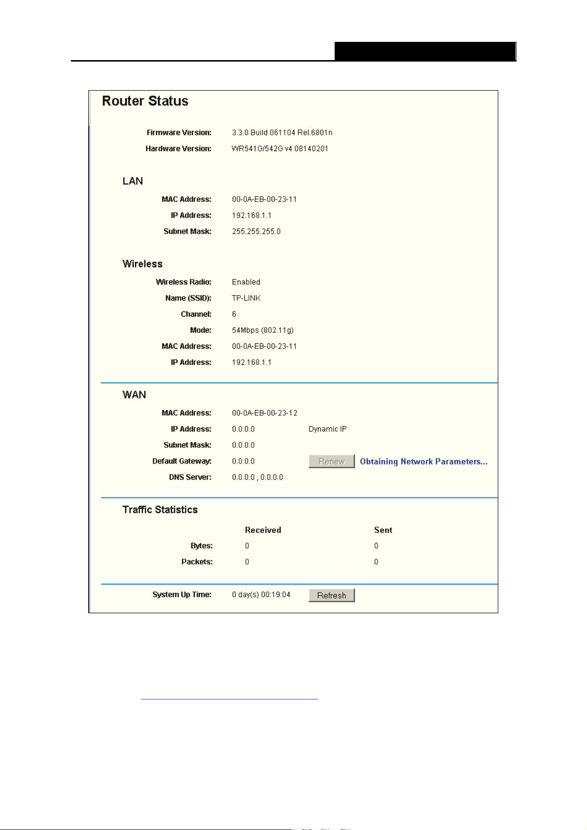
The total up time of the router from when it was switched on or reset.
TL-WR541G 54M Wireless Router User Guide
Figure 4-1 Router Status
4.3 Quick Setup
Please refer to Section 3.2: "Quick Installation Guide."
- 14 -
Page 23
TL-WR541G 54M Wireless Router User Guide
4.4 Network
Figure 4-2 the Network menu
There are three submenus under the Network menu (shown in Figure 4-2): LAN, WAN and MAC
Clone. Click any of them, and you will be able to configure the corresponding function. The
detailed explanations for each submenu are provided below.
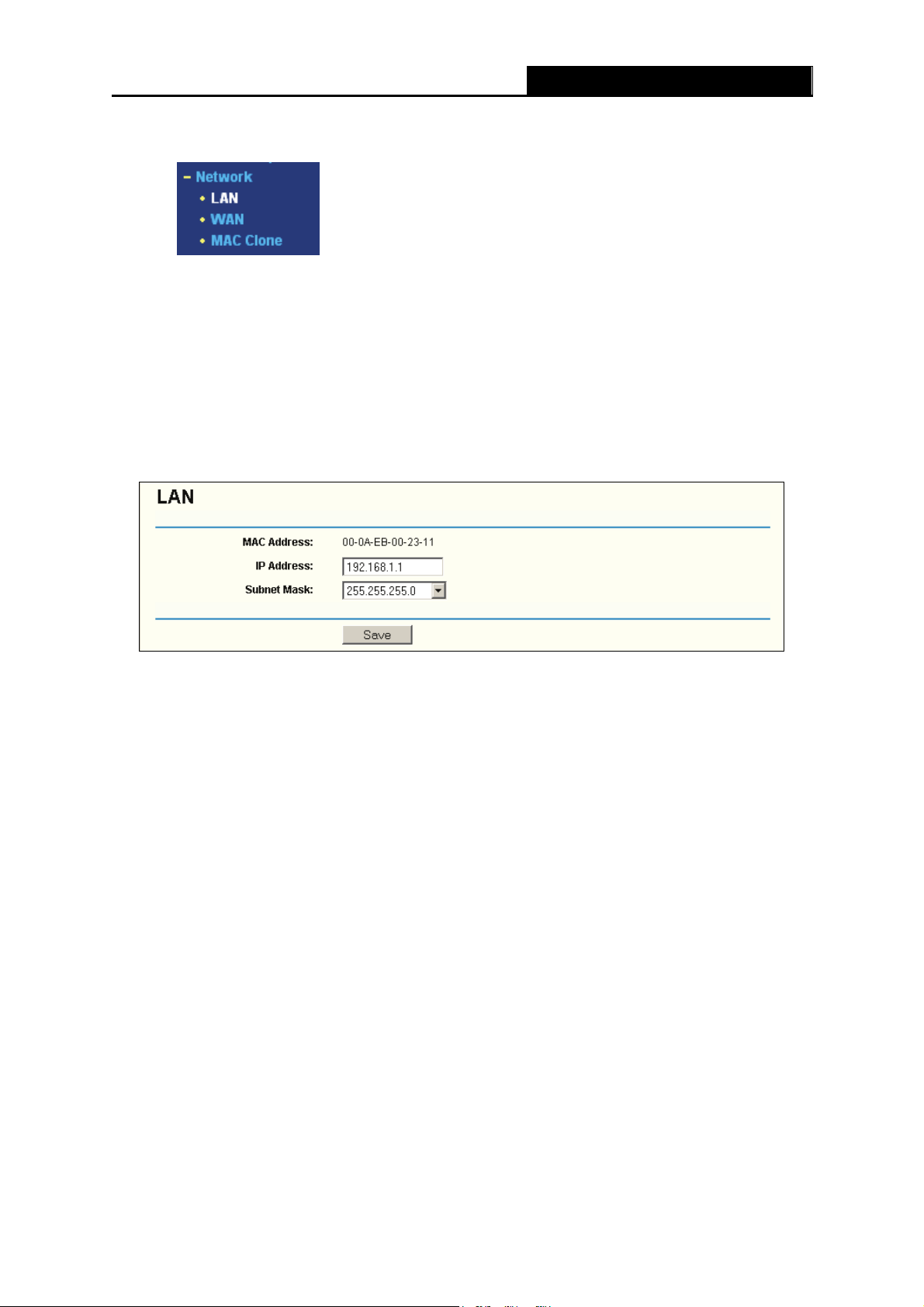
4.4.1 LAN
You can configure the IP parameters of LAN on this page.
Figure 4-3 LAN
¾ MAC Address - The physical address of the router, as seen from the LAN. The value can't
be changed.
¾ IP Address - Enter the IP address of your router in dotted-decimal notation (factory default:
192.168.1.1).
¾ Subnet Mask - An address code that determines the size of the network. Normally use
255.255.255.0 as the subnet mask.
Note:
)
a. If you change the IP Address of LAN, you must use the new IP Address to login the router.
b. If the new LAN IP Address you set is not in the same subnet, the IP Address pool of the
c. If the new LAN IP Address you set is not in the same subnet, the Virtual Server and DMZ
DHCP server will not take effect, until they are re-configured.
Host will change accordingly at the same time.
4.4.2 WAN
You can configure the WAN port parameters on this page.
- 15 -
Page 24
First, please choose the WAN Connection Type (Dynamic IP/Static IP/PPPoE/802.1X + Dynamic
IP/802.1X + Static IP/Big Pond Cable/L2TP/PPTP) for Internet. The default type is Dynamic IP. If
you aren’t given any login parameters (fixed IP Address, logging ID, etc), please select Dynamic
IP. If you are given a fixed IP (static IP), please select Static IP. If you are given a user name and
TL-WR541G 54M Wireless Router User Guide
a password, please select the type of your ISP provided (PPPoE/BigPond/L2TP/PPTP)
are not sure which connection type you use currently, please contact your ISP to obtain the
correct information.
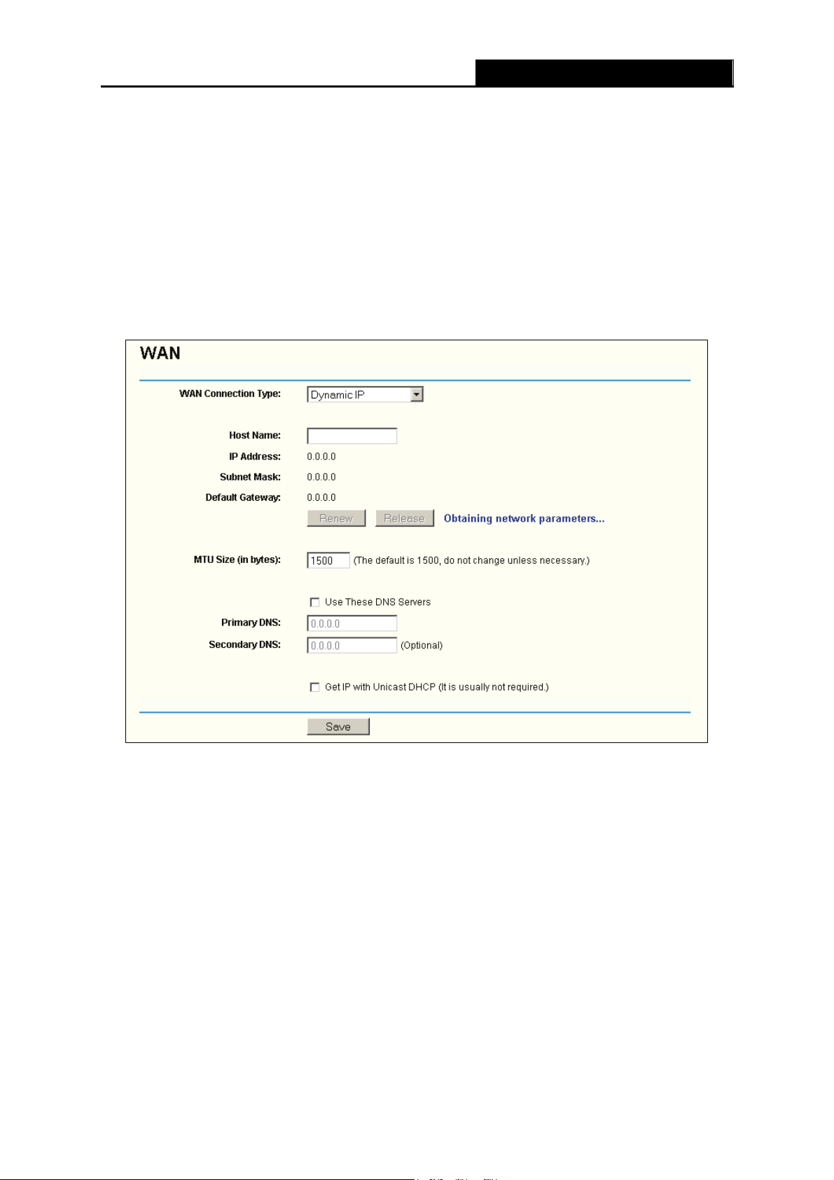
1. If you choose Dynamic IP, the router will automatically get IP parameters from your ISP.
You can see the page as follows (
Figure 4-4):
. If you
Figure 4-4 WAN – Dynamic IP
This page displays the WAN IP parameters assigned dynamically by your ISP, including IP
address, Subnet Mask, Default Gateway, etc. Click the Renew button to renew the IP
parameters from your ISP. Click the Release button to release the IP parameters.
MTU Size - The normal MTU (Maximum Transmission Unit) value for most Ethernet networks
is 1500 Bytes. For some ISPs you need to reduce the MTU. But this is rarely required, and
should not be done unless you are sure it is necessary for your ISP connection.
If your ISP gives you one or two DNS addresses, select Use These DNS Servers and enter
the primary and secondary addresses into the correct fields. Otherwise, the DNS servers will
be assigned dynamically from your ISP.
Note:
)
- 16 -
Page 25
TL-WR541G 54M Wireless Router User Guide
If you get address and find error when you go to a Web site, it is likely that your DNS servers
are set up improperly. You should contact your ISP to get DNS server addresses.
Get IP with Unicast DHCP - A few ISPs' DHCP servers do not support the broadcast
applications. If you cannot get the IP Address normally, you can choose this option. (This is
rarely required.)
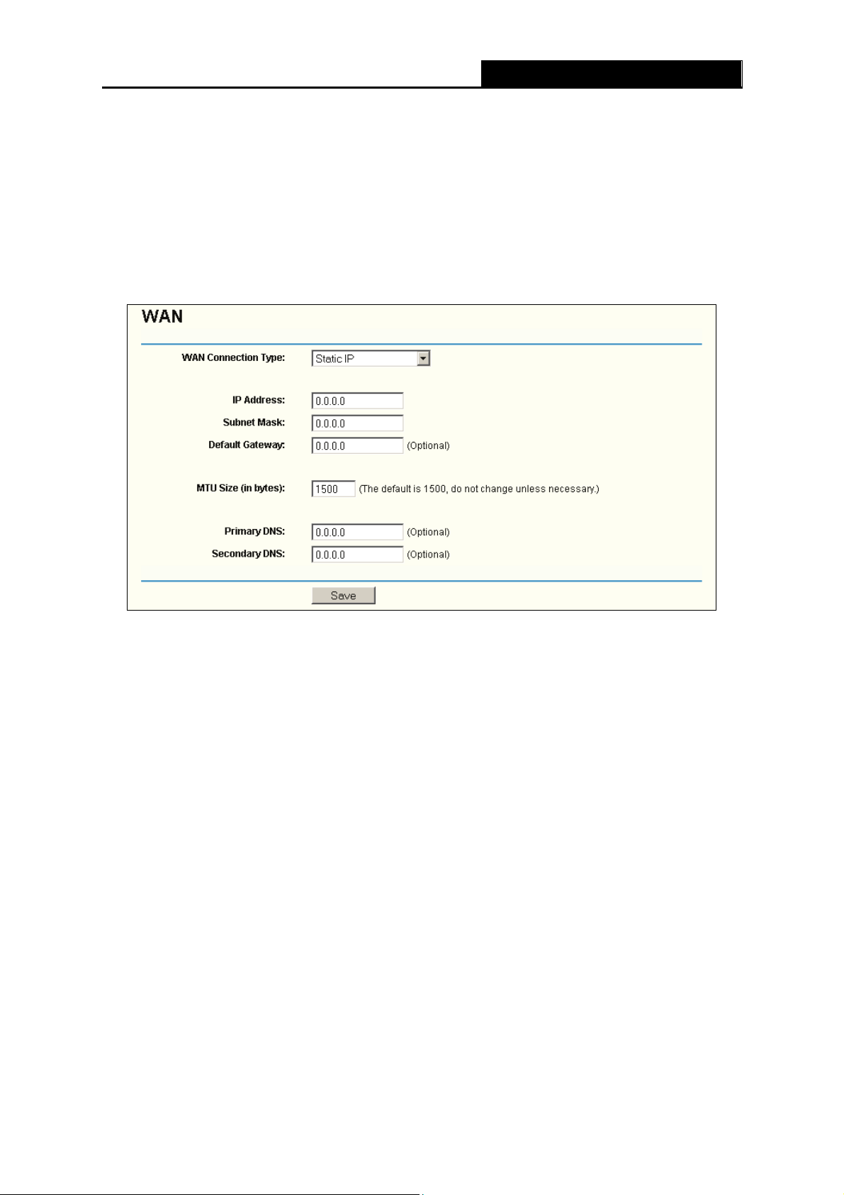
2. If you choose Static IP, you should have fixed IP Parameters specified by your ISP. The
Static IP settings page will appear, shown in
Figure 4-5:
Figure 4-5 WAN - Static IP
You should type the following parameters into the spaces provided:
¾ IP Address - Enter the IP address in dotted-decimal notation provided by your ISP.
¾ Subnet Mask - Enter the subnet Mask in dotted-decimal notation provided by your ISP,
usually is 255.255.255.0.
¾ Default Gateway - (Optional) Enter the gateway IP address in dotted-decimal notation
provided by your ISP.
¾ MTU Size - The normal MTU (Maximum Transmission Unit) value for most Ethernet
networks is 1500 Bytes. For some ISPs you may need to modify the MTU. But this is rarely
required, and should not be done unless you are sure it is necessary for your ISP
connection.
¾ Primary DNS - (Optional) Enter the DNS address in dotted-decimal notation provided by your
ISP.
¾ Secondary DNS - (Optional) Type another DNS address in dotted-decimal notation provided
by your ISP if provided.
- 17 -
Page 26

TL-WR541G 54M Wireless Router User Guide
3. If you choose PPPoE, you should enter the following parameters (Figure 4-6):
Figure 4-6 WAN - PPPoE
¾ User Name/Password - Enter the User Name and Password provided by your ISP. These
fields are case-sensitive.
¾ Connect on Demand - You can configure the router to disconnect your Internet connection
after a specified period of inactivity (Max Idle Time). If your Internet connection has been
terminated due to inactivity, Connect on Demand enables the router to automatically
re-establish your connection as soon as you attempt to access the Internet again. If you wish
to activate Connect on Demand, click the radio button. If you want your Internet connection
to remain active at all times, enter 0 in the Max Idle Time field. Otherwise, enter the number
of minutes you want to have elapsed before your Internet connection terminates.
Caution: Sometimes the connection cannot be disconnected although you specify a time to
Max Idle Time, since some applications is visiting the Internet continually in the background.
¾ Connect Automatically - Connect automatically after the router is disconnected. To use this
option, click the radio button.
¾ Time-based Connecting - You can configure the router to make it connect or disconnect
based on time. Enter the start time in HH:MM format for connecting and end time in HH:MM
format for disconnecting in the Period of Time fields.
Note:
)
Only when you have configured the system time on System Tools -> Time page, will the
Time-based Connecting function can take effect.
- 18 -
Page 27

¾ Connect Manually - You can configure the router to make it connect or disconnect manually.
TL-WR541G 54M Wireless Router User Guide
After a specified period of inactivity (Max Idle Time), the router will disconnect from the
Internet connection, and you will not be able to re-establish your connection automatically as
soon as you attempt to access the Internet again. To use this option, click the radio button. If
you want your Internet connection to remain active at all times, enter "0" in the Max Idle Time
field. Otherwise, enter the number time in minutes that you wish to have the Internet
connecting last unless a new link is requested.
Caution: Sometimes the connection cannot be disconnected although you specify a time to
Max Idle Time, since some applications are visiting the Internet continually in the background.
Click the Connect button to connect immediately. Click the Disconnect button to disconnect
immediately.
Click the Advanced Settings button to set up the advanced option, the page shown in Figure
4-7 will then appear:
Figure 4-7 PPPoE Advanced Settings
¾ Packet MTU - The default MTU size is 1480 bytes, which value is usually fine. For some
ISPs, you need modify the MTU. This should not be done unless you are sure it is necessary
for your ISP.
¾ Service Name/AC Name - The service name and AC (Access Concentrator) name, these
should not be configured unless you are sure it is necessary for your ISP.
¾ ISP Specified IP Address - If you know that your ISP does not automatically transmit your IP
address to the router during login, click “Use the IP Address specified by ISP” check box
- 19 -
Page 28

TL-WR541G 54M Wireless Router User Guide
and enter the IP Address in dotted-decimal notation, which your ISP provided.
¾ Detect Online Interval - The default value is 0, you can input the value between 0 and 120.
The router will detect Access Concentrator online at every interval between seconds. If the
value is 0, it means, do not detect.
¾ DNS IP address - If you know that your ISP does not automatically transmit DNS addresses
to the router during login, click “Use the following DNS servers” checkbox and enter the IP
address in dotted-decimal notation of your ISP’s primary DNS server. If a secondary DNS
server address is available, enter it as well.
Click the Save button to save your settings.
4. If you choose 802.1X + Dynamic IP, you should enter the follow parameters(Figure 4-8) :
Figure 4-8 802.1X + Dynamic IP Settings
User Name - Enter the user name for 802.1X authentication provided by your ISP
¾
¾ Password - Enter the password for 802.1X authentication provided by your ISP.
Click Login to start 802.1X authentication.
Click Logout to end 802.1X authentication.
- 20 -
Page 29

¾ Host Name - This field is required to be filled by some service provider.
TL-WR541G 54M Wireless Router User Guide
5. If you choose 802.1X + Static IP, you should enter the follow parameters(Figure 4-9) :
Figure 4-9 802.1X + Static IP Settings
¾ User Name - Enter the user name for 802.1X authentication provided by your ISP
¾ Password - Enter the password for 802.1X authentication provided by your ISP.
Click Login to start 802.1X authentication.
Click Logout to end 802.1X authentication.
¾ IP Address - Enter the IP address in dotted-decimal notation provided by your ISP.
¾ Subnet Mask - Enter the subnet Mask in dotted-decimal notation provided by your ISP.
¾ Default Gateway - (Optional) Enter the default gateway IP address in dotted-decimal
notation provided by your ISP.
6. If you choose Big Pond Cable, you should enter the following parameters (
Figure 4-10):
- 21 -
Page 30

TL-WR541G 54M Wireless Router User Guide
Figure 4-10 Big Pond Settings
¾ User Name/Password - Enter the User Name and Password provided by your ISP. These
fields are case-sensitive.
¾ Auth Server - Enter the authenticating server IP address or host name.
¾ Auth Domain - Type in the domain suffix server name based on your location. Egg,
NSW / ACT - nsw.bigpond.net.au
VIC / TAS / WA / SA / NT - vic.bigpond.net.au
QLD - qld.bigpond.net.au
¾ Connect on Demand - You can configure the router to disconnect from your Internet
connection after a specified period of inactivity (Max Idle Time). If your Internet connection
has been terminated due to inactivity, Connect on Demand enables the router to
automatically re-establish your connection as soon as you attempt to access the Internet
again. If you wish to activate Connect on Demand, click the radio button. If you want your
Internet connection to remain active at all times, enter 0 in the Max Idle Time field. Otherwise,
enter the number of minutes you want to have elapsed before your Internet connection
terminates.
Caution: Sometimes the connection cannot be disconnected although you specify a time to
Max Idle Time, since some applications are visiting the Internet continually in the background.
¾ Connect Automatically - Connect automatically after the router is disconnected. To use this
- 22 -
Page 31

TL-WR541G 54M Wireless Router User Guide
option, click the radio button.
¾ Connect Manually - You can configure the router to make it connect or disconnect manually.
After a specified period of inactivity (Max Idle Time), the router will disconnect from your
Internet connection, and you will not be able to re-establish your connection automatically as
soon as you attempt to access the Internet again. To use this option, click the radio button. If
you want your Internet connection to remain active at all times, enter "0" in the Max Idle Time
field. Otherwise, enter the number in minutes that you wish to have the Internet connecting
last unless a new link is requested.
Caution: Sometimes the connection cannot be disconnected although you specify a time to
Max Idle Time, since some applications are visiting the Internet continually in the background.
Click the Connect button to connect immediately. Click the Disconnect button to disconnect
immediately.
7. If you choose L2TP, you should enter the following parameters (
Figure 4-11):
Figure 4-11 L2TP Settings
- 23 -
Page 32

¾ User Name/Password - Enter the User Name and Password provided by your ISP. These
TL-WR541G 54M Wireless Router User Guide
fields are case-sensitive.
¾ Dynamic IP/ Static IP – Choose either as you are given by your ISP.
Click the Connect button to connect immediately. Click the Disconnect button to disconnect
immediately.
¾ Connect on Demand - You can configure the router to disconnect from your Internet
connection after a specified period of inactivity (Max Idle Time). If your Internet connection
has been terminated due to inactivity, Connect on Demand enables the router to
automatically re-establish your connection as soon as you attempt to access the Internet
again. If you wish to activate Connect on Demand, click the radio button. If you want your
Internet connection to remain active at all times, enter 0 in the Max Idle Time field. Otherwise,
enter the number of minutes you want to have elapsed before your Internet connection
terminates.
Caution: Sometimes the connection cannot be disconnected although you specify a time to
Max Idle Time, since some applications is visiting the Internet continually in the background.
¾ Connect Automatically - Connect automatically after the router is disconnected. To use this
option, click the radio button.
¾ Connect Manually - You can configure the router to make it connect or disconnect manually.
After a specified period of inactivity (Max Idle Time), the router will disconnect from your
Internet connection, and you will not be able to re-establish your connection automatically as
soon as you attempt to access the Internet again. To use this option, click the radio button. If
you want your Internet connection to remain active at all times, enter "0" in the Max Idle Time
field. Otherwise, enter the number in minutes that you wish to have the Internet connecting
last unless a new link is requested.
Caution: Sometimes the connection cannot be disconnected although you specify a time to
Max Idle Time, since some applications is visiting the Internet continually in the background.
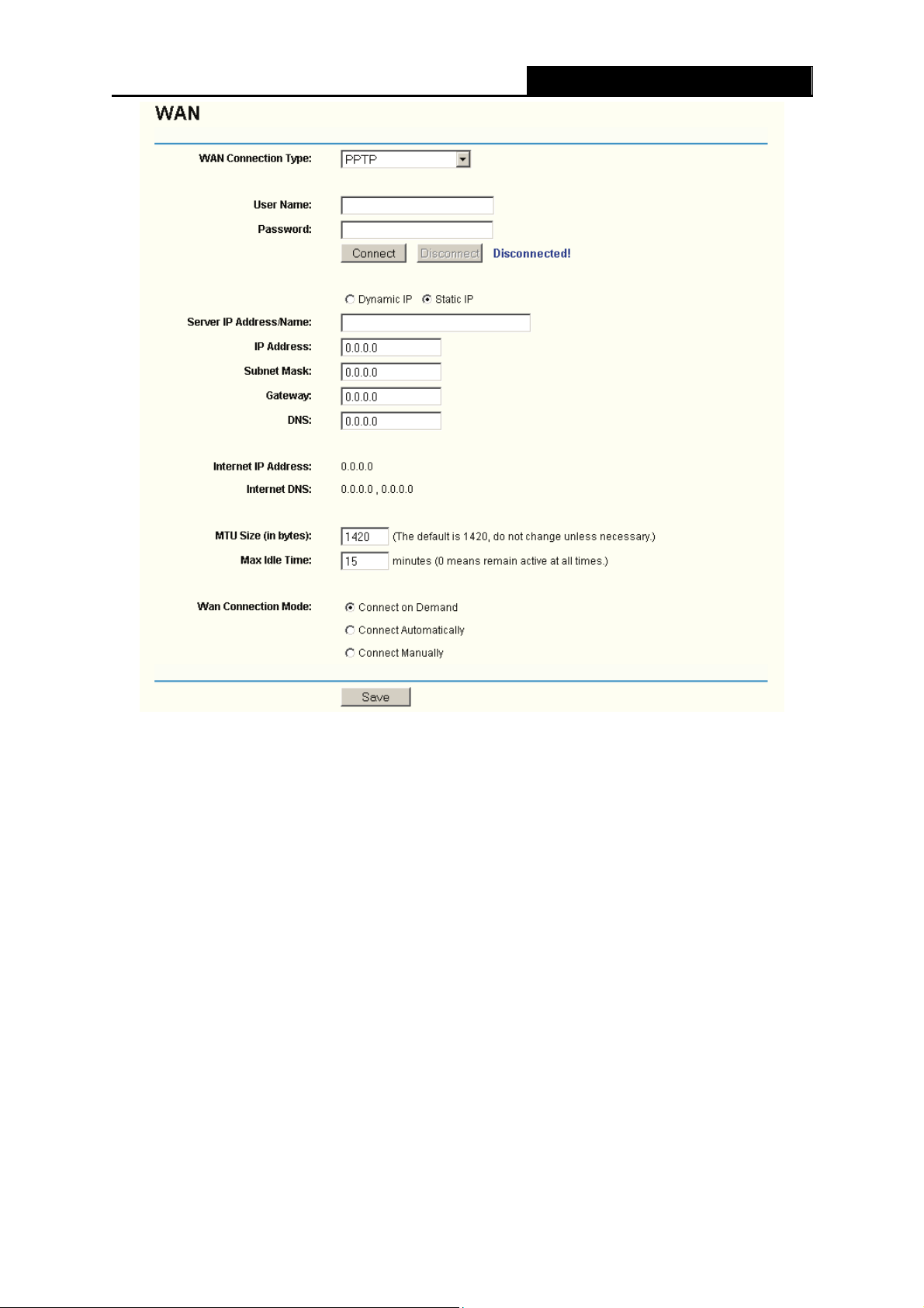
8. If you choose PPTP, you should enter the following parameters (
Figure 4-12):
- 24 -
Page 33
TL-WR541G 54M Wireless Router User Guide
Figure 4-12 PPTP Settings
¾ User Name/Password - Enter the User Name and Password provided by your ISP. These
fields are case-sensitive.
¾ Dynamic IP/ Static IP – Choose either as you are given by your ISP and enter the ISP’s IP
address or the domain name.
If you choose static IP and enter the domain name, you should also enter the DNS assigned
by your ISP. And click the Save button.
Click the Connect button to connect immediately. Click the Disconnect button to disconnect
immediately.
¾ Connect on Demand - You can configure the router to disconnect from your Internet
connection after a specified period of inactivity (Max Idle Time). If your Internet connection
has been terminated due to inactivity, Connect on Demand enables the router to
automatically re-establish your connection as soon as you attempt to access the Internet
again. If you wish to activate Connect on Demand, click the radio button. If you want your
Internet connection to remain active at all times, enter 0 in the Max Idle Time field. Otherwise,
- 25 -
Page 34
TL-WR541G 54M Wireless Router User Guide
enter the number of minutes you want to have elapsed before your Internet connection
terminates.
Caution: Sometimes the connection cannot be disconnected although you specify a time to
Max Idle Time, since some applications are visiting the Internet continually in the background.
¾ Connect Automatically - Connect automatically after the router is disconnected. To use this
option, click the radio button.
¾ Connect Manually - You can configure the router to make it connect or disconnect manually.
After a specified period of inactivity (Max Idle Time), the router will disconnect from your
Internet connection, and you will not be able to re-establish your connection automatically as
soon as you attempt to access the Internet again. To use this option, click the radio button. If
you want your Internet connection to remain active at all times, enter "0" in the Max Idle Time
field. Otherwise, enter the number in minutes that you wish to have the Internet connecting
last unless a new link is requested.
Caution: Sometimes the connection cannot be disconnected although you specify a time to
Max Idle Time, since some applications are visiting the Internet continually in the background.
4.4.3 MAC Clone
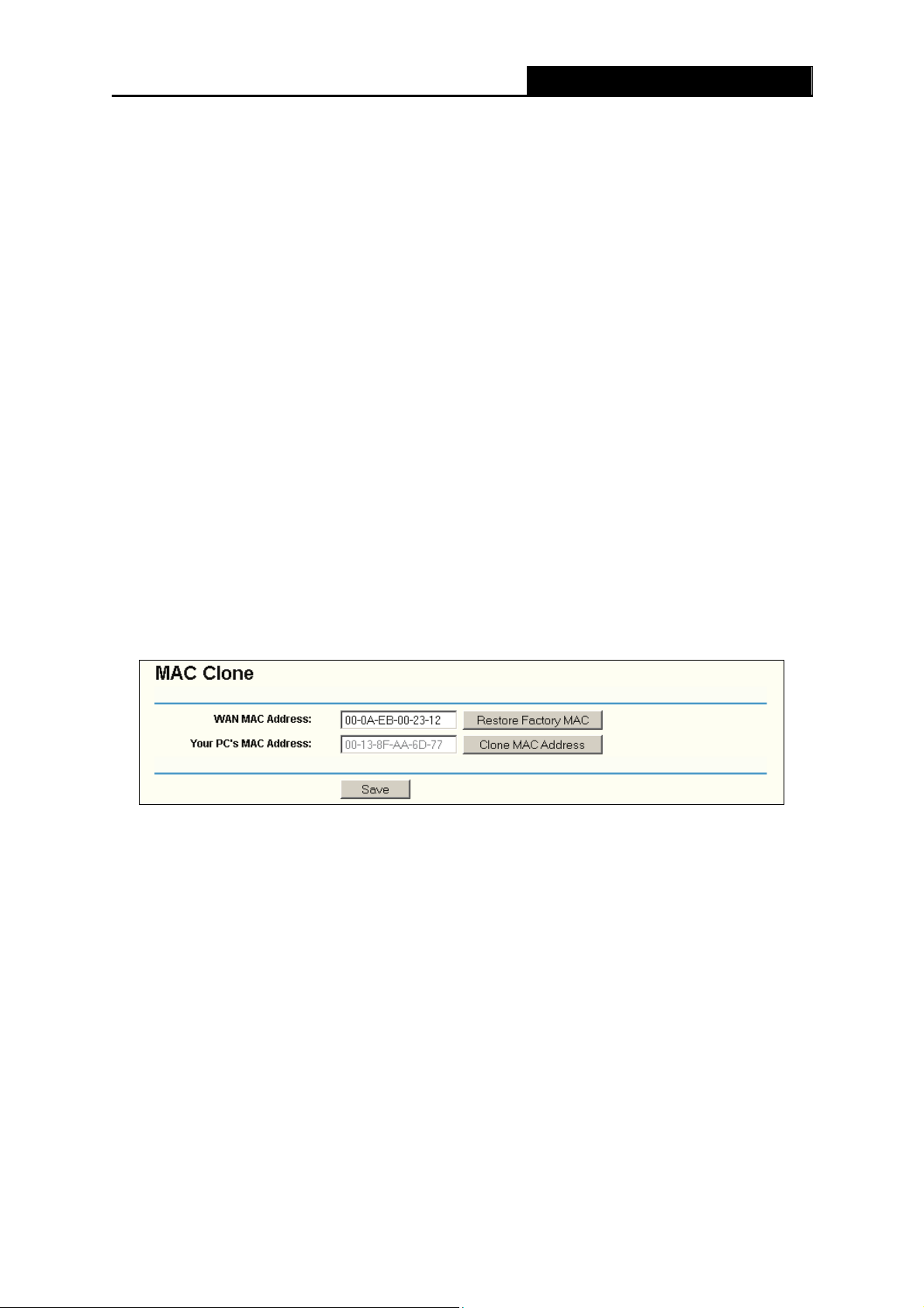
You can configure the MAC address of the WAN port on this page, Figure 4-13:
Figure 4-13 MAC Address Clone
Some ISPs require that you register the MAC Address of your adapter, which is connected to your
cable/DSL Modem or Ethernet during installation. Changes are rarely needed here.
¾ WAN MAC Address - This field displays the current MAC address of the WAN port, which is
used for the WAN port. If your ISP requires that you register the MAC address, please enter
the correct MAC address into this field. The format for the MAC Address is
XX-XX-XX-XX-XX-XX (X is any hexadecimal digit).
¾ Your PC's MAC Address - This field displays the MAC address of the PC that is managing
the router. If the MAC address is required, you can click the Clone MAC Address button
and this MAC address will fill in the WAN MAC Address field.
Click Restore Factory MAC to restore the MAC address of WAN port to the factory default
value.
- 26 -
Page 35

Click the Save button to save your settings.
Note:
)
1) Only the PC on your LAN can use the MAC Address Clone feature.
2) If you click the Save button, the router will prompt you to reboot.
TL-WR541G 54M Wireless Router User Guide
4.5 Wireless
Figure 4-14 Wireless menu
There are three submenus under the Wireless menu (shown in Figure 4-14): Wireless Settings,
MAC Filtering and Wireless Statistics. Click any of them, and you will be able to configure the
corresponding function. The detailed explanations for each submenu are provided below.
4.5.1 Wireless Settings
The basic settings for the wireless network are set on this page, Figure 4-15:
- 27 -
Page 36
TL-WR541G 54M Wireless Router User Guide
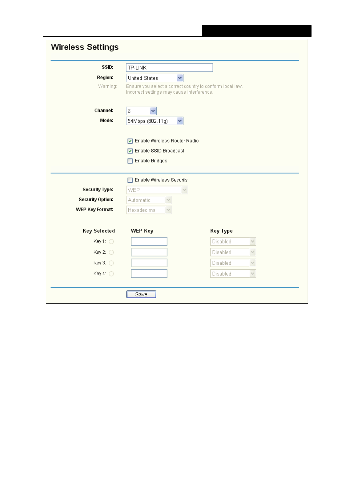
Figure 4-15 Wireless Settings
¾ SSID - Enter a value of up to 32 characters. The same name (SSID) must be assigned to all
wireless devices in your network. The default SSID is TP-LINK, but it is recommended
strongly that you change your networks name (SSID) to a different value. This value is
case-sensitive. For example, TP-LINK is NOT the same as tp-link.
¾ Region - Select your region from the pull-down list. This field specifies the region where the
wireless function of the router can be used. It may be illegal to use the wireless function of
the router in a region other than one of those specified in this field. If your country or region
is not listed, please contact your local government agency for assistance.
The default region is United States. When you select your local region from the pull-down list,
click the Save button, then the Note Dialog appears. Click OK.
- 28 -
Page 37

TL-WR541G 54M Wireless Router User Guide
Note Dialog
Note:
)
Limited by local law regulations, version for North America does not have region selection option.
¾ Channel - This field determines which operating frequency will be used. It is not necessary
to change the wireless channel unless you notice interference problems with another nearby
access point.
¾ Mode - Select the desired wireless mode. The options are:
• 54Mbps (802.11g) - Both 802.11g and 802.11b wireless stations can connect to the
router.
• 11Mbps (802.11b) - Only 802.11b wireless stations can connect to the router.
Note:
)
The default is "54Mbps (802.11g)", which allows both 802.11g and 802.11b wireless stations
to connect to the router.
¾ Enable Wireless Router Radio - The wireless radio of this Router can be enabled or
disabled to allow wireless stations access. If enabled, wireless stations will be able to
access the router. Otherwise, wireless stations will not be able to access.
¾ Enable SSID Broadcast - If you select the Enable SSID Broadcast checkbox, the Wireless
Router SSID will broadcast its name (SSID) on the air.
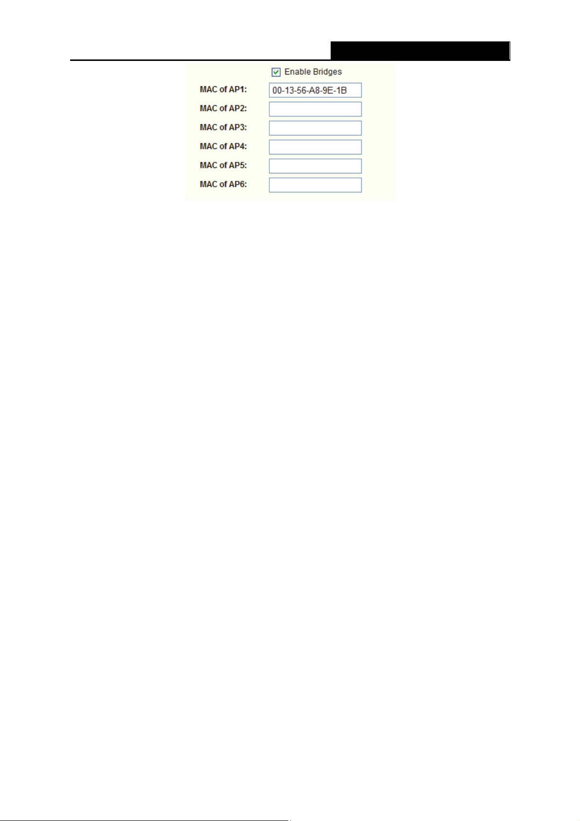
¾ Enable Bridges – If you select the Enable Bridges checkbox, you can input MAC address
of other APs to communicate with them wirelessly in Bridge mode.
• MAC of AP (1-6): Input the MAC address of the AP which you want to communicate with.
There are six entries can be configured.
The APs can communicate with each other in Bridge mode unless they know each other’s
MAC address. For example, if the router whose MAC address is 00-13-56-A8-9E-1A wants
to communicate with an AP whose MAC address is 00-13-56-A8-9E-1B in Bridge mode, you
should do as following:
1. Select Enable Bridges and input 00-13-56-A8-9E-1B as following screen shown.
- 29 -
Page 38
TL-WR541G 54M Wireless Router User Guide
2. Access the AP's Web-based utility and configure the AP under Bridge mode, then input
00-13-56-A8-9E-1A in corresponding Blank.
¾ Enable Wireless Security – The wireless security function can be enabled or disabled. If
disabled, the wireless stations will be able to connect the router without encryption. It is
recommended strongly that you choose this option to encrypt your wireless network. The
encryption settings are described below.
¾ Authentication Type - You can select one of the following authentication types:
• WEP - Select WEP authentication type based on 802.11 authentications.
• WPA-PSK/WPA2-PSK - Select WPA/WPA2 authentication type based on pre-shared
pass phrase.
• WPA /WPA2 - Select WPA/WPA2 authentication type based on Radius Server.
¾ Authentication Options - You can select one of the following authentication options:
• When you select WEP for authentication type you can select the following
authentication options:
• Automatic - Select Shared Key or Open System authentication type automatically
based on the wireless station request.
• Shared Key - select 802.11 Shared Key authentications.
• Open System - Select 802.11 Open System authentications.
• When you select WPA-PSK/WPA2-PSK for authentication type you can select
Automatic, WPA –PSK or WPA2-PSK as authentication options.
• When you select WPA/WPA2 as an authentication type you can select Automatic WPA
or WPA2 as authentication option.
- 30 -
Page 39

¾ WEP Key Format - You can select ASCII or Hexadecimal format. ASCII Code Format
TL-WR541G 54M Wireless Router User Guide
stands for any combination of keyboard characters in the specified length. Hexadecimal
format stands for any combination of hexadecimal digits (0-9, a-f, A-F) in the specified
length.
¾ WEP Key settings - Select which of the four keys will be used and enter the matching WEP
key information for your network in the selected key radio button. These values must be
identical on all wireless stations in your network.
¾ Key Type - You can select the WEP key length (64-bit, or 128-bit, or 152-bit) for encryption.
"Disabled" means the WEP key entry is invalid.
• For 64-bit encryption - You can enter 10 hexadecimal digits (any combination of 0-9, a-f,
A-F, zero key is not permitted) or 5 ASCII characters.
• For 128-bit encryption - You can enter 26 hexadecimal digits (any combination of 0-9,
a-f, A-F, zero key is not permitted) or 13 ASCII characters.
• For 152-bit encryption - You can enter 32 hexadecimal digits (any combination of 0-9,
a-f, A-F, zero key is not permitted) or 16 ASCII characters.
¾ Encryption - When you select WPA-PSK/WPA2-PSK or WPA/WPA2 for Authentication
Type you can select Automatic, TKIP or AES as Encryptions.
Figure 4-16 WPA-PSK/WPA2-PSK
¾ WPA-PSK/WPA2-PSK Passphrase - You can enter a WPA or WPA2 passphrase between
8 and 63 characters long.
¾ Group Key Update Period - Specify the group key update interval in seconds. The value
can be either 0 seconds or from 30 seconds and up, 1-29 seconds are not usable figures.
Enter 0 to disable the update.
- 31 -
Page 40
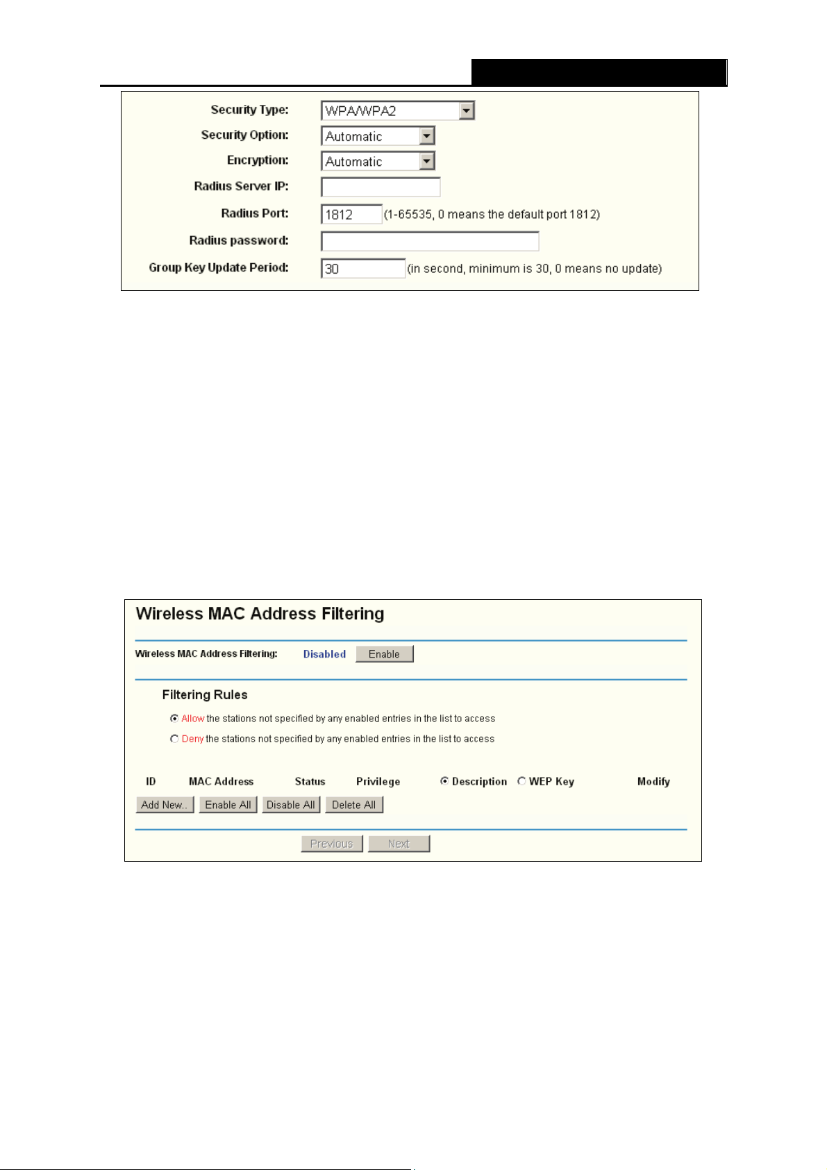
Figure 4-17 WPA/WPA2
¾ Radius Server IP - Enter the IP address of the Radius Server
¾ Radius Port - Enter the port number that the radius service used.
¾ Radius Password - Enter the password for the Radius Server.
TL-WR541G 54M Wireless Router User Guide
Be sure to click the Save button to save your settings on this page.
Note:
)
The router will reboot automatically after you click save.
4.5.2 MAC Filtering
The Wireless MAC Filtering for wireless networks is set on this page, Figure 4-18:
Figure 4-18 Wireless MAC address Filtering
The Wireless MAC Address Filtering feature allows you to control wireless stations accessing the
router, which depend on the station's MAC addresses.
¾ MAC Address - The wireless station's MAC address that you want to access.
¾ Status - The status of this entry either Enabled or Disabled.
¾ Privilege - Select the privileges for this entry. You may select one of the following Allow /
- 32 -
Page 41
TL-WR541G 54M Wireless Router User Guide
Deny / 64-bit / 128-bit / 152-bit.
¾ Description - A simple description of the wireless station.
¾ WEP Key - Specify a unique WEP key (in Hexadecimal format) to access the router.
To set up an entry, follow these instructions:
First, you must decide whether the unspecified wireless stations can access the router or not. If
you desire that the unspecified wireless stations can access the router, please select the radio
button Allow the stations not specified by any enabled entries in the list to access,
otherwise, select the radio button Deny the stations not specified by any enabled entries in
the list to access.
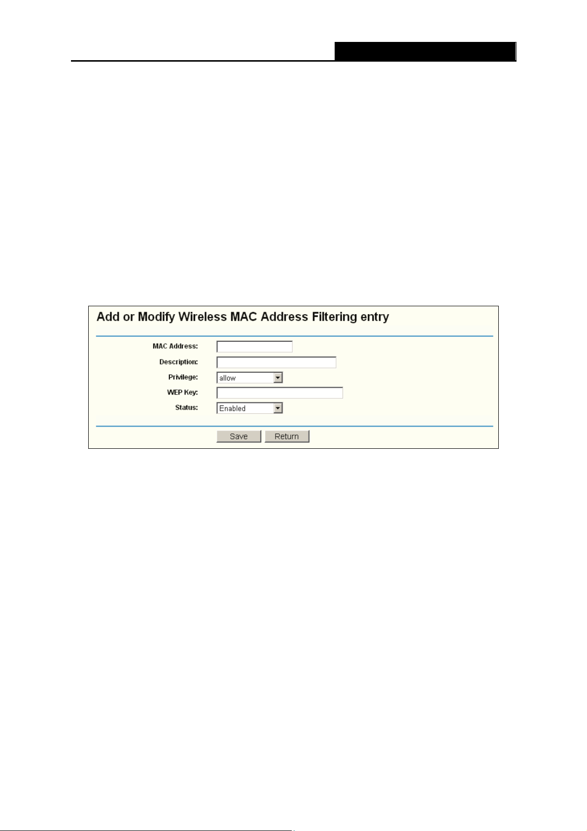
To Add a Wireless MAC Address filtering entry, click the Add New… button. The "Add or Modify
Wireless MAC Address Filtering entry" page will appear, shown in Figure 4-19:
Figure 4-19 Add or Modify Wireless MAC Address Filtering entry
To add or modify a MAC Address Filtering entry, follow these instructions:
1. Enter the appropriate MAC Address into the MAC Address field. The format of the MAC
Address is XX-XX-XX-XX-XX-XX (X is any hexadecimal digit). For example:
00-0A-EB-B0-00-0B.
2. Enter a simple description of the wireless station in the Description field. For example:
Wireless station A.
3. Privilege - Select the privileges for this entry, one of Allow / Deny / 64-bit / 128-bit / 152-bit.
4. WEP Key - If you select 64-bit, 128-bit or 152-bit in the Privilege field, enter any
combination of hexadecimal digits (0-9, a-f, A-F) in the specified length. For example:
2F34D20BE2.
5. Status - Select Enabled or Disabled for this entry on the Status pull-down list.
6. Click the Save button to save this entry.
To add additional entries, repeat steps 1-6.
- 33 -
Page 42

Note:
)
To modify or delete an existing entry:
1. Click the Modify in the entry you want to modify. If you want to delete the entry, click the
Delete.
2. Modify the information.
3. Click the Save button.
Click the Enable All button to make all entries enabled
Click the Disabled All button to make all entries disabled.
Click the Delete All button to delete all entries
Click the Next button to go to the next page and click the Previous button to return to the
previous page.
For example: If you desire that the wireless station A with MAC address 00-0A-EB-00- 07-BE be
When 64-bit, or 128-bit, or 152-bit is selected, WEP Key will be enabled.
TL-WR541G 54M Wireless Router User Guide
able to access the router. The wireless station B with MAC address 00-0A-EB- 00-07-5F not be able
to access the router, and the wireless station C with MAC address 00-0A-EB-00-07-8A be able to
access the router when its WEP key is 2F34D20BE2E 54B326C5476586A, while all other wireless
stations cannot access the router, you should configure the Wireless MAC Address Filtering list
by following these steps:
1. Click the Enable button to enable this function.
2. Select the radio button: Deny the stations not specified by any enabled entries in the list
to access for Filtering Rules.
3. Delete all or disable all entries if there are any entries already.
4. Click the Add New... button and enter the MAC address 00-0A-EB-00-07-BE in the MAC
Address field, enter wireless station A in the Description field, select Allow in the Privilege
pull-down list and select Enabled in the Status pull-down list. Click the Save and the Return
button.
5. Click the Add New... button and enter the MAC address 00-0A-EB-00-07-5F in the MAC
Address field, enter wireless station B in the Description field, select Deny in the Privilege
pull-down list and select Enabled in the Status pull-down list. Click the Save and the Return
button.
6. Click the Add New... button and enter the MAC address 00-0A-EB-00-07-8A in the MAC
Address field, enter wireless station C in the Description field, select 128-bit in the P
pull-down list, enter 2F34D20BE2E54B326C5476586A in the WEP Key field and select
Enabled in the Status pull-down list. Click the Save and the Return button.
- 34 -
rivilege
Page 43

The filtering rules that configured should be similar to the following list:
Note:
)
a) If you select the radio button Allow the stations not specified by any enabled entries
b) If you enable the function and select the Deny the stations not specified by any
in the list to access for Filtering Rules, the wireless station B will still not be able to
access the router, however, other wireless stations that are not in the list will be able to
access the router.
enabled entries in the list to access for Filtering Rules, and there are not any enable
entries in the list, thus, no wireless stations can access the router.
TL-WR541G 54M Wireless Router User Guide
4.5.3 Wireless Statistics
This page shows MAC Address, Current Status, Received Packets and Sent Packets for each
connected wireless station.
Figure 4-20 The router attached wireless stations
¾
MAC Address - The connected wireless station's MAC address
¾ Current Status - The connected wireless station's running status, one of STA-AUTH /
STA-ASSOC / AP-UP / WPA / WPA-PSK /WPA2/WPA2-PSK/None
¾ Received Packets - Packets received by the station
¾ Sent Packets - Packets sent by the station
You cannot change any of the values on this page. To update this page and to show the current
connected wireless stations, click on the Refresh button.
If the numbers of connected wireless stations go beyond one page, click the Next button to go to
the next page and click the Previous button to return the previous page.
Note:
)
- 35 -
This page will be refreshed automatically every 5 seconds.
Page 44

TL-WR541G 54M Wireless Router User Guide
4.6 DHCP
Figure 4-21 The DHCP menu
There are three submenus under the DHCP menu (shown in Figure 4-21): DHCP Settings,
DHCP Clients List and Address Reservation. Click any of them, and you will be able to
configure the corresponding function. The detailed explanations for each submenu are provided
below.
4.6.1 DHCP Settings
The router is set up by default as a DHCP (Dynamic Host Configuration Protocol) server, which
provides the TCP/IP configuration for all the PC(s) that are connected to the router on the LAN.
The DHCP Server can be configured on the page (shown in Figure 4-22):
Figure 4-22 DHCP Settings
¾ DHCP Server - Enable or Disable the DHCP server. If you disable the Server, you must
have another DHCP server within your network or else you must manually configure the
computer.
¾ Start IP Address - This field specifies the first of the addresses in the IP address pool.
192.168.1.100 is the default start address.
¾ End IP Address - This field specifies the last of the addresses in the IP address pool.
192.168.1.199 is the default end address.
¾ Address Lease Time - The Address Lease Time is the amount of time in which a network
user will be allowed connection to the router with their current dynamic IP Address. Enter the
amount of time, in minutes. The user will be "leased" this dynamic IP Address. The range of
- 36 -
Page 45

TL-WR541G 54M Wireless Router User Guide
the time is 1 ~ 2880 minutes. The default value is 120 minutes.
¾ Default Gateway - (Optional.) Suggest to input the IP address of the LAN port of the router,
default value is 192.168.1.1
¾ Default Domain - (Optional.) Input the domain name of your network.
¾ Primary DNS - (Optional.) Input the DNS IP address provided by your ISP. Or consult your
ISP.
¾ Secondary DNS - (Optional.) Input the IP address of another DNS server if your ISP
provides two DNS servers.
Note:
)
To use the DHCP server function of the router, you must configure all computers on the LAN as
"Obtain an IP Address automatically" mode. This function will take effect until the router reboots.
4.6.2 DHCP Clients List
This page shows Client Name, MAC Address, Assigned IP, and Lease Time for each DHCP
Client attached to the router (Figure 4-23):
Figure 4-23 DHCP Clients List
¾ Index - The index of the DHCP Client
¾ Client Name - The name of the DHCP client
¾ MAC Address - The MAC address of the DHCP client
¾ Assigned IP - The IP address that the router has allocated to the DHCP client.
¾ Lease Time - The time of the DHCP client leased. Before the time is up, DHCP client will
request to renew the lease automatically.
You cannot change any of the values on this page. To update this page and to show the current
attached devices, click on the Refresh button.
4.6.3 Address Reservation
When you specify a reserved IP address for a PC on the LAN, that PC will always receive the
same IP address each time when it accesses the DHCP server. Reserved IP addresses should
- 37 -
Page 46

TL-WR541G 54M Wireless Router User Guide
be assigned to servers that require permanent IP settings. This page is used for address
reservation (shown in
¾ MAC Address - The MAC address of the PC of which you want to reserve IP address.
¾ Assigned IP Address - The IP address of the router reserved.
¾ Status - The status of this entry either Enabled or Disabled.
Figure 4-24).
Figure 4-24 Address Reservation
To Reserve IP addresses:
1. Click the Add New button. (Pop-up Figure 4-25)
2.
Enter the MAC address (The format for the MAC Address is XX-XX-XX-XX-XX-XX.) and IP
address in dotted-decimal notation of the computer you wish to add.
3. Click the Save button when finished.
Figure 4-25 Add or Modify an Address Reservation Entry
To modify or delete an existing entry:
1. Click the Modify in the entry you want to modify. If you want to delete the entry, click the
Delete.
2. Modify the information.
3. Click the Save button.
Click the Enable All button to make all entries enabled
Click the Disabled All button to make all entries disabled.
- 38 -
Page 47

TL-WR541G 54M Wireless Router User Guide
Click the Delete All button to delete all entries
Click the Next button to go to the next page and Click the Previous button to return the previous
page.
Note:
)
The function won't take effect until the router reboots.
4.7 Forwarding
Figure 4-26 The Forwarding menu
There are four submenus under the Forwarding menu (shown in Figure 4-26): Virtual Servers,
Port Triggering, DMZ and UPnP. Click any of them, and you will be able to configure the
corresponding function. The detailed explanations for each submenu are provided below.
4.7.1 Virtual Servers
Virtual servers can be used for setting up public services on your LAN, such as DNS, Email and
FTP. A virtual server is defined as a service port, and all requests from the Internet to this service
port will be redirected to the computer specified by the server IP. Any PC that was used for a
virtual server must have a static or reserved IP Address because its IP Address may change
when using the DHCP function. You can set up virtual servers on this page, shown in
Figure 4-27:
Figure 4-27 Virtual Servers
¾ Service Port - The numbers of External Ports. You can type a service port or a range of
service ports (the format is XXX – YYY, XXX is the start port, YYY is the end port).
¾ IP Address - The IP Address of the PC providing the service application.
¾ Protocol - The protocol used for this application, either TCP, UDP, or All (all protocols
supported by the router).
¾ Status - The status of this entry either Enabled or Disabled.
- 39 -
Page 48

To setup a virtual server entry:
1. Click the Add New button. (pop-up Figure 4-28)
2.
Select the service you want to use from the Common Service Port list. If the Common
Service Port list does not have the service that you want to use, type the number of the
service port or service port range in the Service Port box.
3. Type the IP Address of the computer in the Server IP Address box.
4. Select the protocol used for this application, either TCP or UDP, or All.
5. Select the Enable checkbox to enable the virtual server.
6. Click the Save button.
TL-WR541G 54M Wireless Router User Guide
Figure 4-28 Add or Modify a Virtual Server Entry
Note:
)
It is possible that you have a computer or server that has more than one type of available service.
If so, select another service, and enter the same IP Address for that computer or server.
To modify or delete an existing entry:
1. Click the Modify in the entry you want to modify. If you want to delete the entry, click the
Delete.
2. Modify the information.
3. Click the Save button.
Click the Enable All button to make all entries enabled
Click the Disabled All button to make all entries disabled.
Click the Delete All button to delete all entries
Click the Next button to go to the next page and Click the Previous button to return the previous
page.
- 40 -
Page 49
Note:
)
TL-WR541G 54M Wireless Router User Guide
If you set the virtual server of service port as 80, you must set the Web management port on
Security –> Remote Management page to be any value except 80 such as 8080. Or else there
will be a conflict to disable the virtual server.
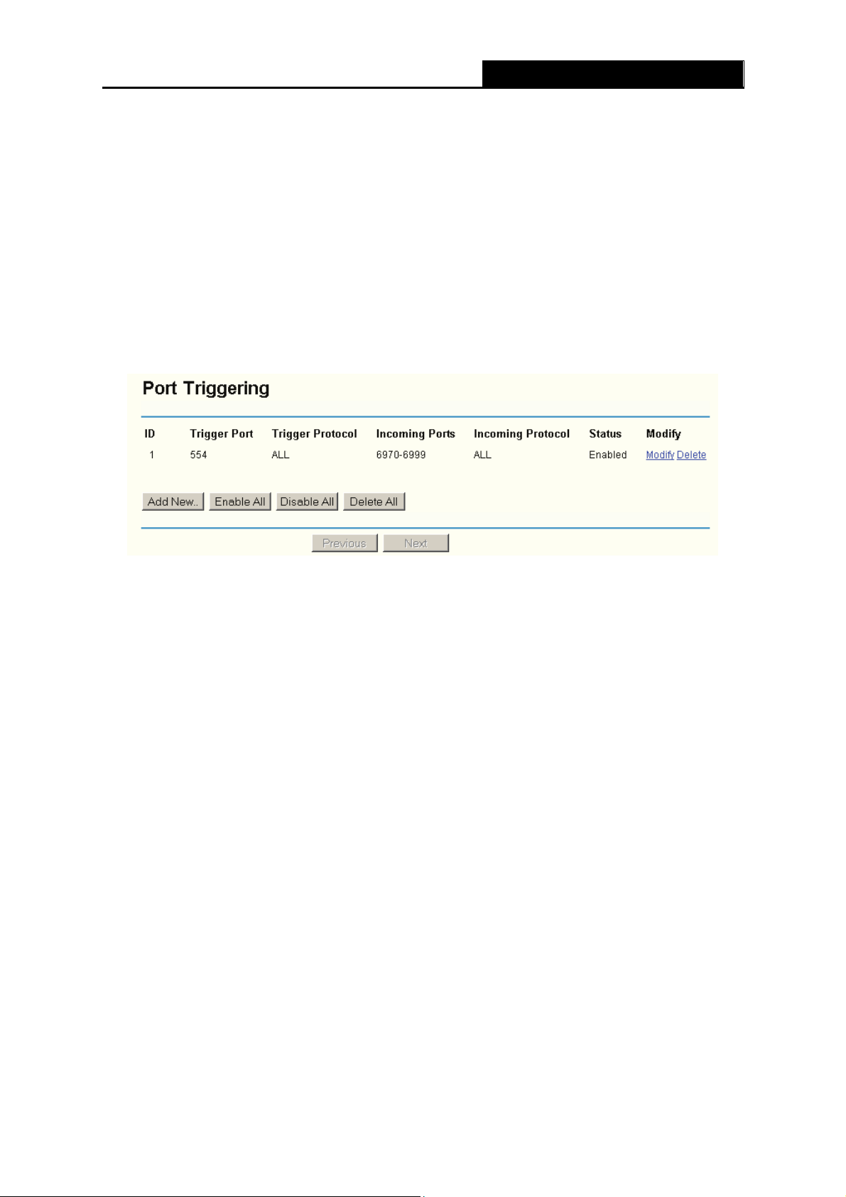
4.7.2 Port Triggering
Some applications require multiple connections, like Internet games, video conferencing, Internet
calling and so on. These applications cannot work with a pure NAT router. Port Triggering is
used for some of these applications that can work with an NAT router. You can set up Port
Triggering on this page shown in
Figure 4-29:
Figure 4-29 Port Triggering
Once configured, operation is as follows:
1. A local host makes an outgoing connection using a destination port number defined in the
Trigger Port field.
2. The router records this connection, opens the incoming port or ports associated with this
entry in the Port Triggering table, and associates them with the local host.
3. When necessary the external host will be able to connect to the local host using one of the
ports defined in the Incoming Ports field.
¾ Trigger Port - The port for outgoing traffic. An outgoing connection using this port will
"Trigger" this rule.
¾ Trigger Protocol - The protocol used for Trigger Ports, either TCP, UDP, or All (all
protocols supported by the router).
¾ Incoming Ports Range - The port or port range used by the remote system when it
responds to the outgoing request. A response using one of these ports will be forwarded to
the PC that triggered this rule. You can input at most 5 groups of ports (or port section).
Every group of ports must be set apart with ",". For example, 2000-2038, 2050-2051, 2085,
3010-3030.
¾ Incoming Protocol - The protocol used for Incoming Ports Range, either TCP or UDP, or
ALL (all protocols supported by the router).
- 41 -
Page 50
¾ Status - The status of this entry either Enabled or Disabled.
TL-WR541G 54M Wireless Router User Guide
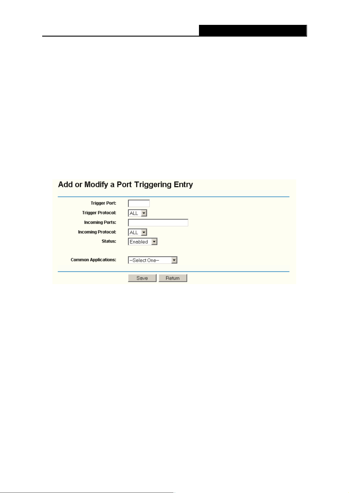
To add a new rule, enter the following data on the Port Triggering screen.
1. Click the Add New button. (pop-up Figure 4-30)
2.
Enter a port number used by the application when it generates an outgoing request.
3. Select the protocol used for Trigger Port from the pull-down list, either TCP, UDP, or All.
4. Enter the range of port numbers used by the remote system when it responds to the PC's
request.
5. Select the protocol used for Incoming Ports Range from the pull-down list, either TCP or
UDP, or All.
6. Select the Enable checkbox to enable.
7. Click the Save button to save the new rule.
Figure 4-30 Add or Modify a Triggering Entry
There are many popular applications in the Popular Application list. You can select it, and the
application will fill in the Trigger Port, incoming Ports Range boxes and select the Enable
checkbox. It has the same effect as adding a new rule.
To modify or delete an existing entry:
1. Click the Modify in the entry you want to modify. If you want to delete the entry, click the
Delete.
2. Modify the information.
3. Click the Save button.
Click the Enable All button to make all entries enabled
Click the Disabled All button to make all entries disabled.
Click the Delete All button to delete all entries
- 42 -
Page 51
Note:
)
1. When the trigger connection is released, the according opening ports will be closed.
2. Each rule allowed to be used only by one host on LAN synchronously. The trigger connection
3. Incoming Port Range cannot overlap each other.
of other hosts on LAN will be refused.
TL-WR541G 54M Wireless Router User Guide
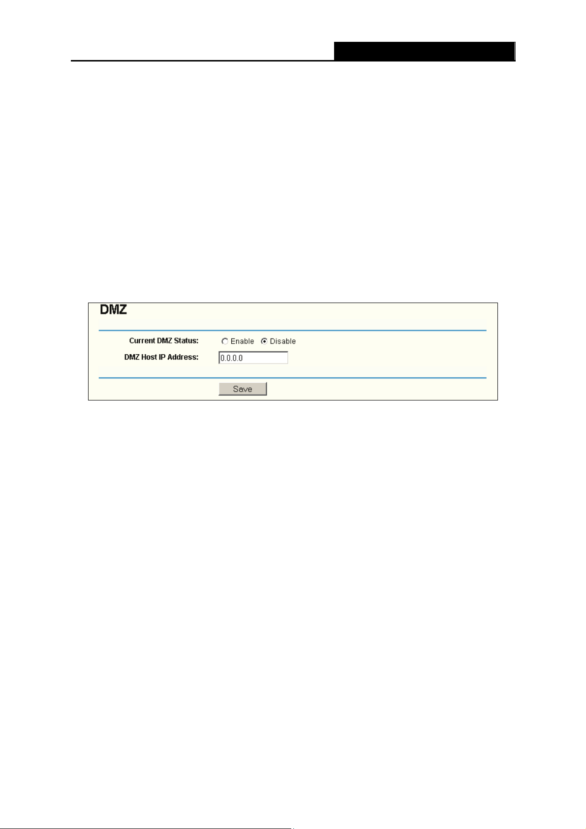
4.7.3 DMZ
The DMZ host feature allows one local host to be exposed to the Internet for a special-purpose
service such as Internet gaming or videoconferencing. DMZ host forwards all the ports at the
same time. Any PC whose port is being forwarded must have its DHCP client function disabled
and should have a new static IP Address assigned to it because its IP Address may change when
using the DHCP function. You can set up DMZ host on this page shown in Figure 4-31:
Figure 4-31 DMZ
To assign a computer or server to be a DMZ server:
1. Click the Enable radio button
2. Enter the local host IP Address in the DMZ Host IP Address field
3. Click the Save button.
Note:
)
After you set the DMZ host, the firewall related to the host will not work.
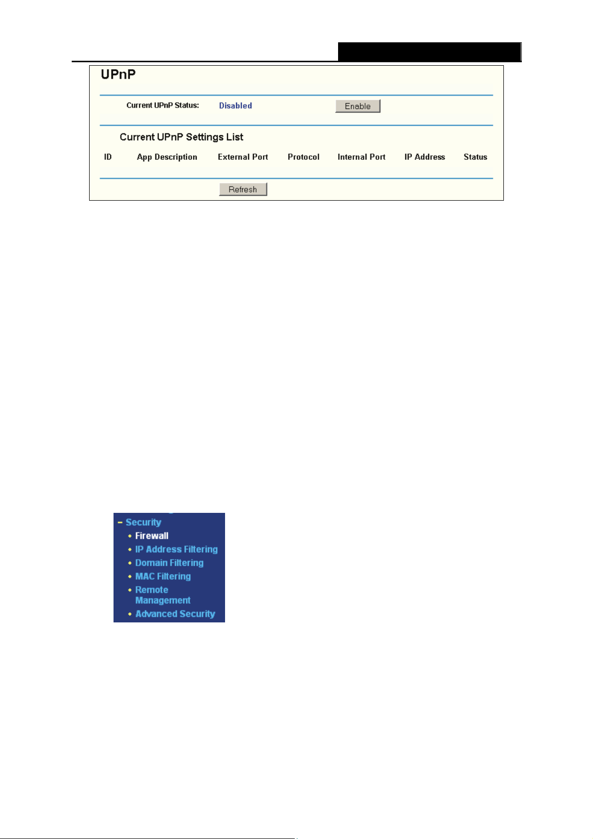
4.7.4 UPnP
The Universal Plug and Play (UPnP) feature allows the devices, such as Internet computers, to
access the local host resources or devices as needed. UPnP devices can be automatically
discovered by the UPnP service application on the LAN. You can configure UPnP on this page
that shown in
Figure 4-32:
- 43 -
Page 52
TL-WR541G 54M Wireless Router User Guide
Figure 4-32 UPnP Setting
¾ Current UPnP Status - UPnP can be enabled or disabled by clicking the Enable or Disable
button. As allowing this may present a risk to security, this feature is disabled by default.
¾ Current UPnP Settings List - This table displays the current UPnP information.
• App Description – The description provided by the application in the UPnP request
• External Port - External port, which the router opened for the application.
• Protocol – Shows which type of protocol is opened.
• Internal Port - Internal port, which the router opened for local host.
• IP Address - The UPnP device that is currently accessing the router.
• Status - Either Enabled or Disabled, “Enabled” means that port is still active. Otherwise,
the port is inactive.
Click Refresh to update the Current UPnP Settings List.
4.8 Security
Figure 4-33 The Security menu
There are six submenus under the Security menu (shown in Figure 4-33): Firewall, IP Address
Filtering, Domain Filtering, MAC Filtering, Remote Management and Advanced Security.
Click any of them, and you will be able to configure the corresponding function. The detailed
explanations for each submenu are provided below.
- 44 -
Page 53
TL-WR541G 54M Wireless Router User Guide
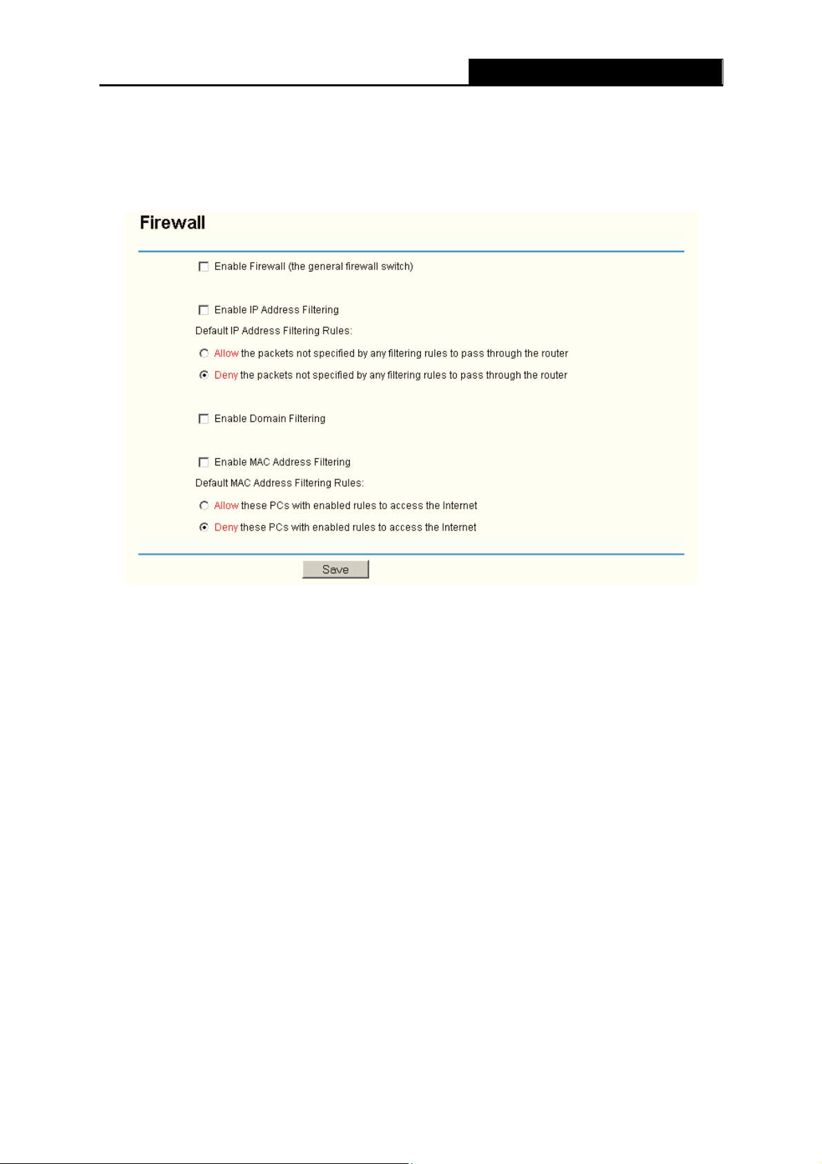
4.8.1 Firewall
Using the Firewall page (shown in Figure 4-34), you can turn the general firewall switch on or off.
The default setting for the switch is off. If the general firewall switch is off, even if IP Address
Filtering, DNS Filtering and MAC Filtering are enabled, their settings are ineffective.
Figure 4-34 Firewall Settings
¾ Enable Firewall - the general firewall switch is on or off.
¾ Enable IP Address Filtering - set IP Address Filtering is enabled or disabled. There are two
default filtering rules of IP Address Filtering, either Allow or Deny passing through the router.
¾ Enable Domain Filtering - set Domain Filtering is enabled or disabled.
¾ Enable MAC Filtering - set MAC Address Filtering is enabled or disabled. You can select the
default filtering rules of MAC Address Filtering, either Allow or Deny accessing the router.
4.8.2 IP Address Filtering
The IP address Filtering feature allows you to control Internet Access by specific users on your
LAN based on their IP addresses. The IP address filtering is set on this page, Figure 4-35:
- 45 -
Page 54
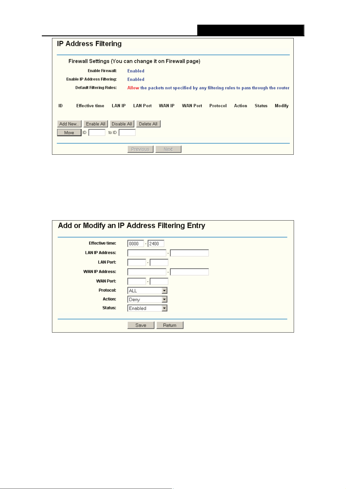
TL-WR541G 54M Wireless Router User Guide
Figure 4-35 IP address Filtering
To disable the IP Address Filtering feature, keep the default setting, Disabled. To set up an IP
Address Filtering entry, click Enable Firewall and Enable IP Address Filtering on the Firewall
page, and click the Add New… button. The page "Add or Modify an IP Address Filtering entry"
will appear shown in
Figure 4-36:
Figure 4-36 Add or Modify an IP Address Filtering Entry
To create or modify an IP Address Filtering entry, please follow these instructions:
1. Effective Time - Enter a range of time in HHMM format, which point to the range time for the
entry to take effect. For example, 0803 - 1705, the entry will take effect from 08:03 to 17:05.
2. LAN IP Address - Enter a LAN IP Address or a range of LAN IP addresses in the field, in
dotted-decimal notation format. For example, 192.168.1.20 - 192.168.1.30. Keep the field
open, which means all LAN IP Addresses have been put into the field.
3. LAN Port - Enter a LAN Port or a range of LAN ports in the field. For example, 1030 - 2000.
Keep the field open, which means all LAN ports have been put into the field.
- 46 -
Page 55

TL-WR541G 54M Wireless Router User Guide
4. WAN IP Address - Enter a WAN IP Address or a range of WAN IP Addresses in the field, in
dotted-decimal notation format. For example, 61.145.238.6 – 61.145.238.47. Keep the field
open, which means all WAN IP Addresses have been put into the field.
5. WAN Port - Enter a WAN Port or a range of WAN Ports in the field. For example, 25 – 110.
Keep the field open, which means all WAN Ports have been put into the field.
6. Protocol - Select which protocol is to be used, either TCP, UDP, or All (all protocols
supported by the router).
7. Action - Select either Allow or Deny through the router.
8. Status - Select Enabled or Disabled for this entry on the Status pull-down list.
9. Click the Save button to save this entry.
To modify or delete an existing entry:
1. Click the Modify in the entry you want to modify. If you want to delete the entry, click the
Delete.
2. Modify the information.
3. Click the Save button.
Click the Enable All button to make all entries enabled
Click the Disabled All button to make all entries disabled.
Click the Delete All button to delete all entries
You can change the entry’s order as desired. Fore entries are before hind entries. Enter the ID
number in the first box you want to move and another ID number in second box you want to move
to, and then click the Move button to change the entry’s order.
Click the Next button to the next page and click the Previous button to return to the previous
page.
For example: If you desire to block E-mail received and sent by the IP Address 192.168.1.7 on
your local network, and to make the PC with IP Address 192.168.1.8 unable to visit the website of
IP Address 202.96.134.12, while other PC(s) have no limit you should specify the following IP
address filtering list:
- 47 -
Page 56
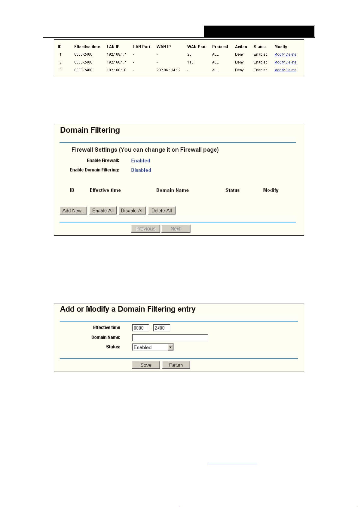
TL-WR541G 54M Wireless Router User Guide
4.8.3 Domain Filtering
The Domain Filtering page (shown in Figure 4-37) allows you to control access to certain websites
on the Internet by specifying their domains or key words.
Figure 4-37 Domain Filtering
Before adding a Domain Filtering entry, you must ensure that Enable Firewall and Enable
Domain Filtering have been selected on the Firewall page. To Add a Domain filtering entry, click
the Add New… button. The page "Add or Modify a Domain Filtering entry” will appear, shown
in Figure 4-38:
Figure 4-38 Add or Modify a Domain Filtering entry
To add or modify a Domain Filtering entry, follow these instructions:
1. Effective Time - Enter a range of time in HHMM format specifying the time for the entry to
take effect. For example, if you enter: 0803 - 1705, than the entry will take effect from 08:03
to 17:05.
2. Domain Name - Type the domain or key word as desired in the field. A blank in the domain
field means all websites on the Internet. For example: www.xxyy.com.cn
- 48 -
, .net.
 Loading...