

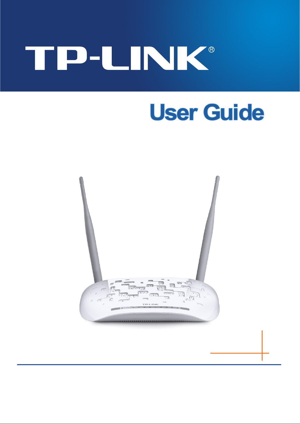
Page 1
Rev: 1.1.0
1910011604
TD-W9970/TD-9970B
300Mbps Wireless N USB VDSL/ADSL Modem Router
Page 2

COPYRIGHT & TRADEMARKS
Specifications are subject to change without notice.
TP-LINK TECHNOLOGIES CO., LTD. Other brands and product names are trademarks or
registered trademarks of their respective holders.
No part of the specifications may be reproduced in any form or by any means or used to make any
derivative such as translation, transformation, or adaptation without permission from TP-L INK
TECHNOLOGIES CO., LTD. Copyright © 2016 TP-LINK TECHNOLOGIES CO., LTD. All rights
reserved.
http://www.tp-link.com
is a registered trademark of
Page 3

FCC STATEMENT
This equipment has been tested and found to comply with the limits for a Class B digital device,
pursuant to part 15 of the FCC Rules. These limits are designed to provide reasonable protection
against harmful interference in a residential installation. This equipment generates, uses and can
radiate radio frequency energy and, if not installed and used in accordance with the instructions,
may cause harmful interference to radio communications. However, there is no guarantee that
interference will not occur in a particular installation. If this equipment does cause harmful
interference to radio or television reception, which can be determined by turning the equipment off
and on, the user is encouraged to try to correct the interference by one or more of the following
measures:
• Reorient or relocate the receiving antenna.
• Increase the separation between the equipment and receiver.
• Connect the equipment into an outlet on a circuit different from that to which the receiver
is connected.
• Consult the dealer or an experienced radio/ TV technician for help.
This device complies with part 15 of the FCC Rules. Operation is subject to the following two
conditions:
1) This device may not cause harmful interference.
2) This device must accept any interference received, including interference that may cause
undesired operation.
Any changes or modifications not expressly approved by the party responsible for compliance
could void the user’s authority to operate the equipment.
Note: The manufacturer is not responsible for any radio or tv interference caused by unauthorized
modifications to this equipment. Such modifications could void the user’s authority to operate the
equipment.
FCC RF Radiation Exposure Statement
This equipment complies with FCC RF radiation exposure limits set forth for an uncontrolled
environment. This device and its antenna must not be co-located or operating in conjunction with
any other antenna or transmitter.
“To comply with FCC RF exposure compliance requirements, this grant is applicable to only
Mobile Configurations. The antennas used for this transmitter must be installed to provide a
separation distance of at least 20 cm from all persons and must not be co-located or operating in
conjunction with any other antenna or transmitter.”
Page 4

CE Mark Warning
This is a class B product. In a domestic environment, this product may cause radio interference, in
which case the user may be required to take adequate measures.
RF Exposure Information
This device meets the EU requirements (1999/5/EC Article 3.1a) on the limitation of exposure of
the general public to electromagnetic fields by way of health protection.
The device complies with RF specifications when the device used at 20 cm from your body.
Продукт сертифіковано згідно с правилами системи УкрСЕПРО на відповідність вимогам
нормативних документів та вимогам, що передбачені чинними законодавчими актами
України.
Safety Information
When product has power button, the power button is one of the way to shut off the product;
when there is no power button, the only way to completely shut off power is to disconnect the
product or the power adapter from the power source.
Don’t disassemble the product, or make repairs yourself. You run the risk of electric shock
and voiding the limited warranty. If you need service, please contact us.
Avoid water and wet locations.
Adapter shall be installed near the equipment and shall be easily accessible.
The plug considered as disconnect device of adapter.
Use only power supplies which are provided by manufacturer and in the original
packing of this product. If you have any questions, please don't hesitate to contact us
Page 5

This product bears the selective sorting symbol for Waste electrical and electronic
European directive 2012/19/EU in order to be recycled or dismantled to minimize
User has the choice to give his product to a competent recycling organization or to
Explanation of the symbols on the product label
Symb ol Explanation
DC voltage
RECYCLING
equipment (WEEE). This means that this product must be handled pursuant to
its impact on the environment.
the retailer when he buys a new electrical or electronic equipment.
Page 6

CONTENTS
Package Contents ................................................................................................................ 1
Chapter 1. Product Overview ............................................................................................ 2
1.1 Overview of the Modem Router ........................................................................................2
1.2 Main Features ....................................................................................................................3
1.3 Panel Layout ......................................................................................................................4
1.3.1 The Front Panel ...........................................................................................................4
1.3.2 The Back Panel ...........................................................................................................6
Chapter 2. Connecting the Modem Router .................................................................... 7
2.1 System Requirements .......................................................................................................7
2.2 Installation Environment Requirements ............................................................................7
2.3 Connecting the Modem Router .........................................................................................8
Chapter 3. Quick Insta llation Guide................................................................................. 9
3.1 TCP/IP Configuration ........................................................................................................9
3.2 Quick Installation Guide ..................................................................................................10
Chapter 4. Configuring the Modem Router ................................................................. 15
4.1 Login ................................................................................................................................15
4.2 Status...............................................................................................................................15
4.3 Quick Setup .....................................................................................................................17
4.4 Operation Mode ...............................................................................................................17
4.5 Network............................................................................................................................17
4.5.1 WAN Settings ............................................................................................................ 18
4.5.2 3G/4G Settings .......................................................................................................... 35
4.5.3 Interface Grou ping ..................................................................................................... 37
4.5.4 LAN Settings ............................................................................................................. 39
4.5.5 IPv6 LAN Settin gs ...................................................................................................... 41
4.5.6 MAC Clone ................................................................................................................ 43
4.5.7 ALG Settings ............................................................................................................. 43
4.5.8 DSL Settings ............................................................................................................. 45
4.5.9 IPSec VPN ................................................................................................................ 45
4.6 IP T V .................................................................................................................................50
4.7 DHCP Server ...................................................................................................................52
Page 7

4.7.1 DHCP Settings .......................................................................................................... 52
4.7.2 Clients List................................................................................................................. 54
4.7.3 Address Reservatio n .................................................................................................. 54
4.7.4 Condition al Pool......................................................................................................... 55
4.8 W ireless ...........................................................................................................................56
4.8.1 Basic Settings............................................................................................................ 56
4.8.2 WPS Settings ............................................................................................................ 58
4.8.3 Wireless Security ....................................................................................................... 61
4.8.4 Wireless Schedule ..................................................................................................... 63
4.8.5 Wireless MAC Filtering ............................................................................................... 63
4.8.6 Wireless Ad vanced .................................................................................................... 65
4.8.7 Wireless Status.......................................................................................................... 66
4.9 Guest Network .................................................................................................................67
4.9.1 Basic Settings............................................................................................................ 67
4.9.2 Guest Network Status ................................................................................................ 68
4.10 USB Settings ...................................................................................................................69
4.10.1 USB Mass Storage ................................................................................................... 69
4.10.2 User Accounts .......................................................................................................... 70
4.10.3 Storag e Sharing ........................................................................................................ 71
4.10.4 FTP Server............................................................................................................... 72
4.10.5 Media Server ............................................................................................................ 74
4.10.6 Print Server .............................................................................................................. 75
4.11 Route Settings .................................................................................................................76
4.11.1 Default Gateway ....................................................................................................... 76
4.11.2 Static Route ............................................................................................................. 76
4.11.3 RIP Settings ............................................................................................................. 77
4.12 IPv6 Rout e Settings .........................................................................................................78
4.12.1 IPv6 Default Gateway ............................................................................................... 78
4.12.2 IPv6 Static Route ...................................................................................................... 78
4.13 Forwarding .......................................................................................................................79
4.13.1 Virtual Servers .......................................................................................................... 79
4.13.2 Port Triggeri ng .......................................................................................................... 81
4.13.3 DMZ ........................................................................................................................ 83
4.13.4 UPnP ....................................................................................................................... 83
4.14 Parental Control...............................................................................................................84
4.15 Firewall ............................................................................................................................85
Page 8

4.15.1 Rule ......................................................................................................................... 86
4.15.2 LAN Hos t ................................................................................................................. 87
4.15.3 WAN Host ................................................................................................................ 88
4.15.4 Schedule.................................................................................................................. 89
4.16 IPv6 Firewall ....................................................................................................................90
4.16.1 IPv6 Rul e ................................................................................................................. 90
4.16.2 IPv6 LAN Host .......................................................................................................... 92
4.16.3 IPv6 WAN Host ........................................................................................................ 93
4.16.4 IPv6 Schedule .......................................................................................................... 93
4.17 IPv6 Tunnel......................................................................................................................94
4.18 Bandwidth Control ...........................................................................................................97
4.19 IP & MAC Binding ............................................................................................................98
4.19.1 Bindin g Settings........................................................................................................ 98
4.19.2 ARP List................................................................................................................... 99
4.20 Dynamic DNS ................................................................................................................100
4.21 Diagnostic ......................................................................................................................100
4.22 System Tools .................................................................................................................101
4.22.1 System Log ............................................................................................................ 101
4.22.2 Tim e Settings ......................................................................................................... 102
4.22.3 Manage Control ...................................................................................................... 103
4.22.4 CWMP Settings ...................................................................................................... 104
4.22.5 SNMP Settings ....................................................................................................... 105
4.22.6 Backup & Restor e................................................................................................... 106
4.22.7 Factory Defaults ..................................................................................................... 106
4.22.8 Firmware Upgrade .................................................................................................. 107
4.22.9 Reboot ................................................................................................................... 108
4.22.10 Statistics ............................................................................................................. 108
4.23 Logout ............................................................................................................................110
Appendix A: Specifications ........................................................................................... 111
Appendix B: Troubleshooting....................................................................................... 112
Page 9

TD-W9970/TD-W9970B
300Mbps Wireless N USB VDSL/ADSL Mode m Router User Guide
Package Contents
The following contents should be found in your package:
One 300Mbps Wireless N USB VDSL/ADSL Modem Router
One Power Adapter for 300Mbps Wireless N USB VDSL/ADSL Modem Router
Quick Installation Guide
Technical Support card
One RJ45 cable
Two RJ11 cables
One DSL splitter
Note:
Make sure that the package contains the above items. If any of the listed items are damaged or
missing, please contact your distributor.
1
Page 10

TD-W9970/TD-W9970B
300Mbps Wireless N USB VDSL/ADSL Mode m Router User Guide
Chapter 1. Product Overview
Thank you for choosing the TD-W9970/TD-W9970B 300Mbps Wireless N USB VDSL/ADSL
Modem Router.
1.1 Overview of the Modem Router
The modem router integrates 4-port Switch, Firewall, NAT-Router and Wireless AP. The Modem
Router delivers exceptional range and speed, which can fully meet the need of Small Office/Home
Office (SOHO) networks and the users demanding higher networking performance.
The modem router utilizes integrated VDSL2 transceiver and high speed MIPS CPU. The modem
router supports full-rate VDSL2 connectivity conforming to the ITU and ANSI specifications.
In addition to the basic DMT physical layer functions, the VDSL2 PHY supports dual latency
VDSL2 framing (fast and interleaved) and the I.432 ATM Physical Layer.
The modem router provides up to 300Mbps (2. 4GHz) wireless connection with other 802.11n wireless
clients. The incredible speed makes it ideal for handling multiple data streams at the same time, which
ensures your network stable and smooth. The performance of this 802.11n wireless Router will g ive
you the unexpected networking experience at speed much faster than 802.11g. It is also compat ible
with all IEEE 802.11g and IEEE 802.11b products.
With multiple protection measures, including SSID broadcast control and wireless LAN 64/128
WEP encryption, Wi-Fi protected Access (WPA2-PSK, WPA-PSK), as well as advanced Firewall
protections, the modem router provides complete data privacy.
The modem router provides flexible access control, so that parents or network administrators can
establish restricted access policies for children or staff. It also supports Virtual Server and DMZ
host for Port Triggering, and then the network administrators can manage and monitor the network
in real time with the remote management function.
Since the modem router is compatible with virtually all the major operating systems, it is ve r y easy
to manage. Quick Setup Wizard is supported and detailed instructions are provided step by step in
this user guide. Before installing the modem router, please look through this guide to know all the
modem router’s functions.
2
Page 11

TD-W9970/TD-W9970B
300Mbps Wireless N USB VDSL/ADSL Mode m Router User Guide
1.2 Main Features
Complies with IEEE 802.11n to provide a wireless data rate of up to 300Mbps (2.4GHz).
Four 10/100Mbps Auto-Negotiation RJ45 LAN ports (Auto MDI/MDIX), one RJ11 port.
Provides external splitter.
Adopts Advanced DMT modulation and demodulation technology.
Supports bridge mode and Router function.
Multi-user sharing a high-speed Internet connection.
Downstream data rates up to 100Mbps, upstream data rates up to 60Mbps.
Supports long transfers, the max line length can reach to 6.5Km.
Supports remote configuration and management through SNMP and CWMP.
Supports PPPoE, it allows connecting the internet on demand and disconnecting from the
Internet when idle.
Provides reliable ESD and surge-protect function with quick response semi-conductive surge
protection circuit.
High speed and asymmetrical data transmit mode, provides safe and exclusive bandwidth.
Compatible with all mainstreams DSLAM (CO).
Provides integrated access of internet and route function which face to SOHO user.
Real-time Configuration and device monitoring.
Supports Multiple PVC (Permanent Virtual Circuit).
Built-in DHCP server.
Built-in firewall, supporting IP/MAC filter and URL filter.
Supports Virtual Server, DMZ host and Port Triggering.
Supports Dynamic DNS, UPnP and Static Routing.
Supports system log and flow Statistics.
Supports firmware upgrade and Web-Management page.
Provides WPA-PSK/WPA2-PSK data security, TKIP/AES encryption security.
Provides 64/128-bit WEP encryption security and wireless LAN ACL (Access Control List).
Supports USB Storage Sharing, Print Server, FTP Server, Media Server.
Supports Ethernet WAN (EWAN).
Supports Bandwidth Control.
Supports IPv6.
Supports ADSL and VDSL.
3
Page 12
TD-W9970/TD-W9970B
300Mbps Wireless N USB VDSL/ADSL Modem Router User Guide
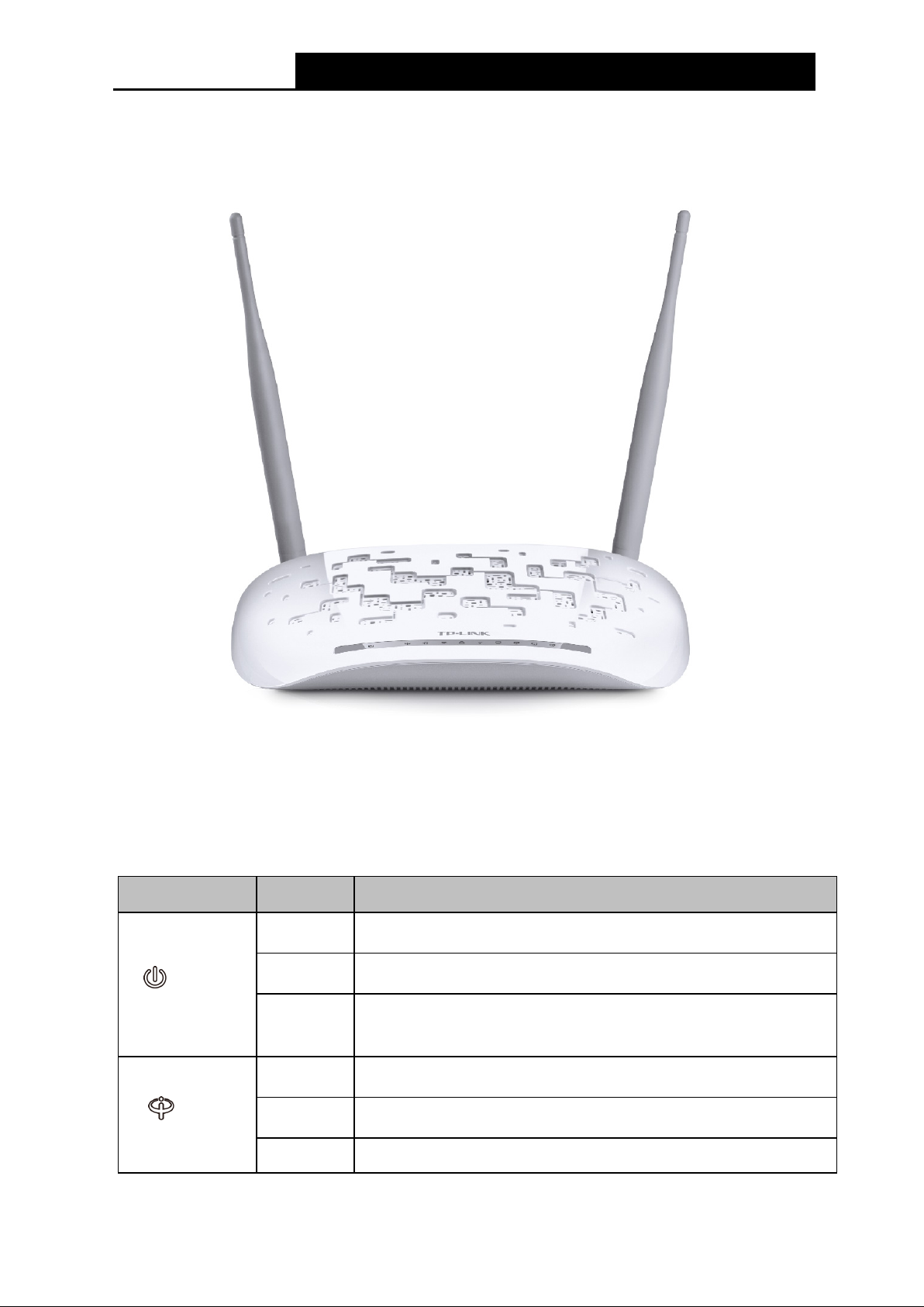
1.3 Panel Layout
is off. Please ensure that the power adapter is
DSL synchronization
1.3.1 The Front Panel
Figure 1-1
The modem router’s LEDs are located on the front panel (View from left to right). They indicate the
device’s working status. For details, please refer to LED Explanation.
LED Explanation:
Name Status Indication
(Power)
(DSL)
On
Flash
Off
On
Flash
Off
System start-up complete.
System starting up or device updating.
The modem router
connected correctly.
DSL line is synchronized and ready to use.
The DSL negotiation is in progress.
There is no connection to the DSL Port or
4
Page 13
TD-W9970/TD-W9970B
300Mbps Wireless N USB VDSL/ADSL Modem Router User Guide
fails. Please refer to Note 1 for troubleshooting.
It turns on when a wireless device has been successfully
connected to the network via WPS. After about 5 minutes, the
handshaking is in process and will continue for about 2
minutes. Please press the WPS/RESET button on other wireless
devices that you want to add to the network while the LED is
(Internet)
(Wireless)
(WPS)
(USB)
On
Off
On
Off The wireless function is disabled.
On/Off
Flash
On
Flash
The network is available with a successful Internet connection.
There is no successful Internet connection or the modem router
is operating in Bridge mode. Please refer to Note 2
troubleshooting.
The wireless function is working properly.
WPS LED will turn off.
WPS
flashing.
The USB device is identified and ready to use.
The USB device is being identified.
for
Off No USB device is plugged in to the USB port.
On
(L AN1-4)
Off
Note :
1. If the DSL LED is off, please check your Internet connection first. Refer to 2.3 Connecting the
Mo de m Router for more information about how to make Internet connection correctly. If you
have already made a right connection, please contact your ISP to make sure if your Internet
service is available now.
2. If the Internet LED is off, please check your DSL LED first. If your DSL LED is also off, please
refer to Note 1
may need to check this part of information with your ISP and make sure everything have been
input correctly.
3. You can also refer to 4.8.2 WPS Settings for more information.
. If your DSL LED is GREEN ON, please check your Internet configuration. You
There is a device connected to this LAN port.
There is no device connected to this LAN port.
5
Page 14
TD-W9970/TD-W9970B
300Mbps Wireless N USB VDSL/ADSL Modem Router User Guide
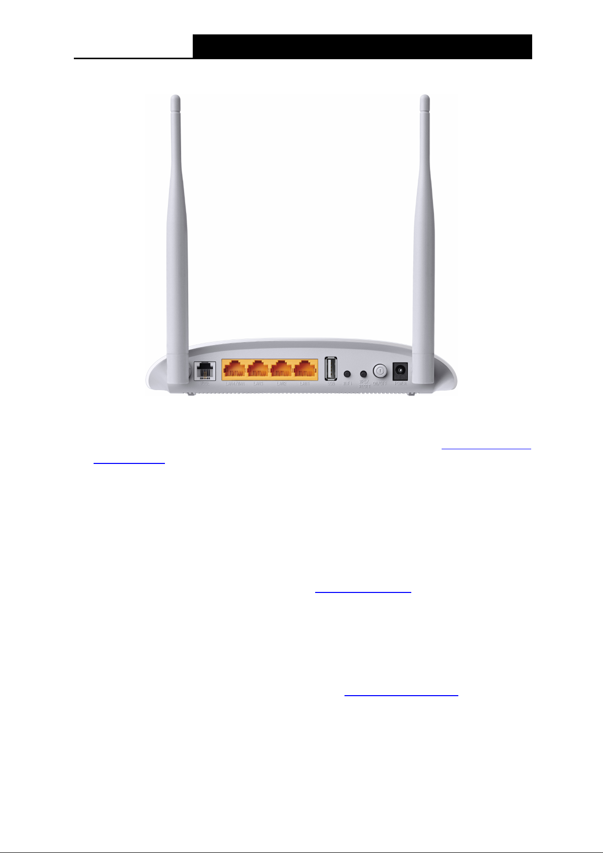
1.3.2 The Back Panel
Figure 1-2
VDSL: Through the port, you can connect the modem router with the telephone. Or you can
connect them by an external separate splitter. For details, please refer to
2.3 Connecting the
Modem Router.
LAN4/WAN, LAN3, L AN2, L AN1 : Through these p orts, you can connect the modem router to
your PC or the other Ethernet network devices. In wireless router mode you will be able to
connect to Cable/FTTH/VDSL/ADSL device.
USB: The USB port connects to a USB storage device, a USB printer or a 3G/4G Modem.
WiFi: The switch for the WiFi function. Press the button to enable/disable the WiFi function.
WPS/RESET: The switch for the WPS function or resetting the modem router.
• WPS function: For details, please refer to 4.8.2 WPS Settings.
• Re set the mode m router: There are two ways to reset the modem router' s facto r y
defaults.
Method one: With the modem router powered on, use a pin to press and hold the
WPS/Reset button for at least 5 seconds. And the modem router will reboot to its factory
default settings.
Method two: Restore the default setting from 4.22.7 Factory Defaults
router's Web-based management page.
ON/OFF: The switch for the power.
POWER: The Power plug is where you will connect the power adapter.
Antennas: Used for wireless operation and data transmit.
6
of the modem
Page 15
TD-W9970/TD-W9970B
300Mbps Wireless N USB VDSL/ADSL Modem Router User Guide
Chapter 2. Connecting the Modem Router
2.1 System Requirements
Broadband Internet Access Service (DSL/Cable/Ethernet).
PCs with a working Ethernet Adapter and an Ethernet cable with RJ45 connectors.
TCP/IP protocol on each PC.
Web browser, such as Microsoft Internet Explorer, Mozilla Firefox or Apple Safari.
2.2 Installation Environment Requirements
The Product should not be located where it will be exposed to moisture or excessive heat.
Place the modem router in a location where it can be connected to the various devices as well
as to a power source.
Make sure the cables and power cord are safely placed out of the way so they do not create a
tripping hazard.
The modem router can be placed on a shelf or desktop.
Keep away from the strong electromagnetic radiation and the device of electromagnetic
sensitive.
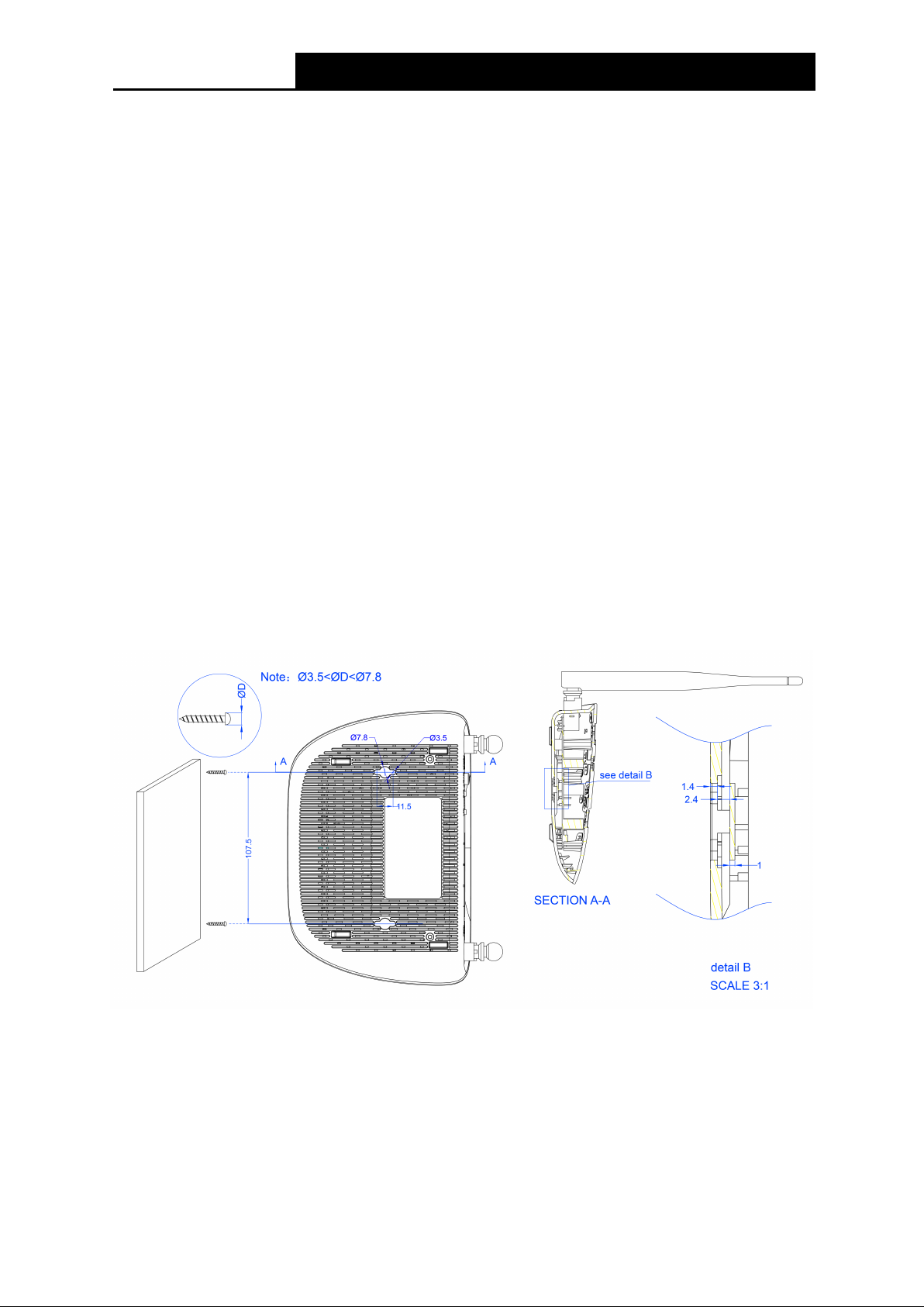
Generally, the modem router is placed on a horizontal s urface. T he device also can be mounted on the
wall as shown in
Figure 2-1.
Figure 2-1 Wall-mount install
7
Page 16
TD-W9970/TD-W9970B
300Mbps Wireless N USB VDSL/ADSL Modem Router User Guide
:
Note :
The diameter of the screw, 3.5mm<D<7.8mm, and the distance of two screws is 107.5mm. T he
screw that project from the wall need around 4mm based, and the length of the screw need to be
at least 20mm to withstand the weight of the product.
2.3 Connecting the Modem Router
Before installing the device, please make sure your broadband service provided by your ISP is
available. If there is any problem, please contact your ISP. Before cable connection, cut off the
power supply and keep your hands dry. You can follow the steps below to install it.
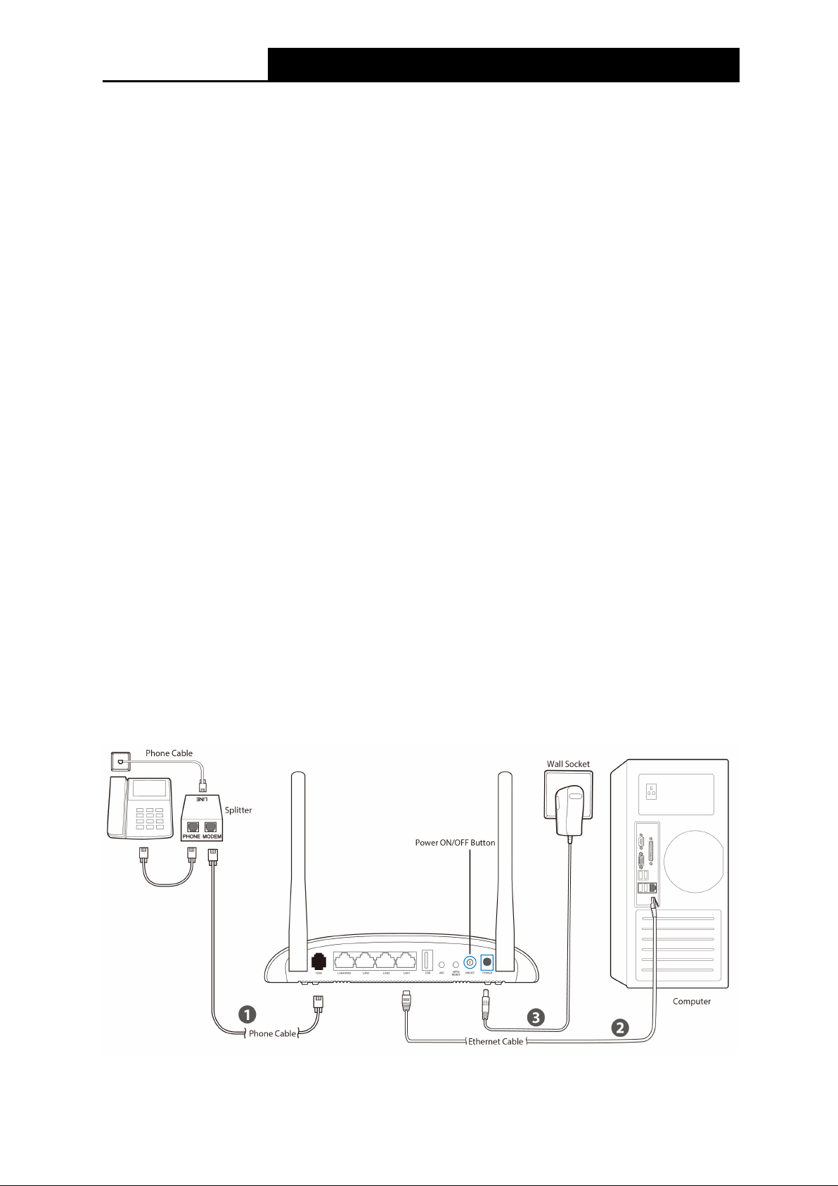
Step 1: Connect the DSL Line.
Me thod one : Plug one end of the twisted-pair DSL cable into the VDSL port on the rear
panel of the modem router, and insert the other end into the wall socket.
Method two
voice, and then you can access the Internet and make calls at the same time. The
external splitter has three ports:
• LINE: Connect to the wall jack
You can use a separate splitter. External splitter can divide the data and
• PHONE: Connect to the phone sets
• MODEM: Connect to the VDSL port of the modem router
Plug one end of the twisted-pair DSL cable into the VDSL port on the rear panel of the
modem router. Connect the other end to the MODEM port of the external splitter.
Step 2: Connect the Ethernet cable. Attach one end of a network cable to your computer’s
Ethernet port or a regular hub/switch port, and the other end to the LAN port on the
modem router.
Step 3: Power on the computers and LAN devices.
Step 4: Attach the power adapter. Connect the power adapter to the power connector on the rear
of the device and plug in the adapter to an electrical outlet or power extension. The
electrical outlet shall be installed near the device and shall be easily accessible.
Figure 2-2
8
Page 17
TD-W9970/TD-W9970B
300Mbps Wireless N USB VDSL/ADSL Modem Router User Guide
Chapter 3. Quick Installation Guide
This chapter will show you how to configure the basic functions of your modem router using Qu ick
Setu p Wizard within minutes.
3.1 TCP/IP Configuration
The default IP address of the modem router is 192.168.1.1. And the default Subnet Mask is
255.255.255.0. These values can be changed as you desire. In this guide, we use all the default
values for description.
Connect the local PC to the LAN/ W A N port of the modem router. And then you can configure the
IP address for your PC in the following way.
Obtain an IP address automatically
1) Set up the TCP/IP Protocol in "Obtain an IP address automatically" mode on your PC.
If you need instructions as to how to do this, please refer to
shooting.
2) Then the built-in DHCP server will assign IP address for the PC.
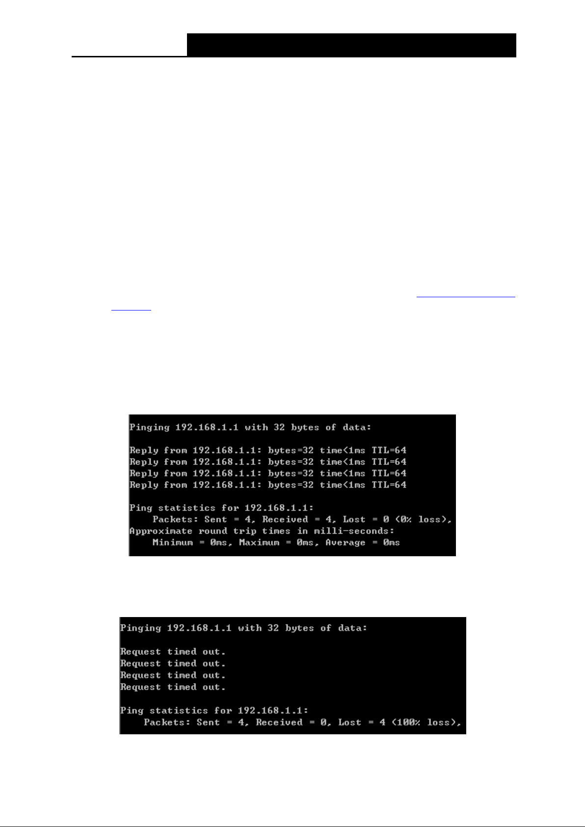
Now, you can run the Ping command in the command prompt to verify the network connection.
Please click the Start menu on your desktop, select run tab, type cmd or command in the field
and press Enter. Type ping 192.168.1.1 on the next screen, and then press Enter.
Appendix B: Trouble
If the result displayed is similar to the screen below, the connection between your PC and the
modem router has been established.
Figure 3-1
If the result displayed is similar to the screen shown below, it means that your PC has not
connected to the modem router.
Figure 3-2
9
Page 18
TD-W9970/TD-W9970B
300Mbps Wireless N USB VDSL/ADSL Modem Router User Guide
You can check it following the steps below:
1) Is the connection between your PC and the modem router correct?
The LEDs of LAN port which you link to the device and the LEDs on your PC's adapter should
be lit.
2) Is the TCP/IP configuration for your PC correct?
If the modem router's IP address is 192.168.1.1, your PC's IP address must be within the
range of 192.168.1.2 ~ 192.168.1.254.
3.2 Quick Installation Guide
With a Web-based management page, it is easy to configure and manage the modem router. The
Web-based management page can be used on any Windows, Macintosh or UNIX OS with a Web
browser, such as Microsoft Internet Explorer, Mozilla Firefox or Apple Safari.
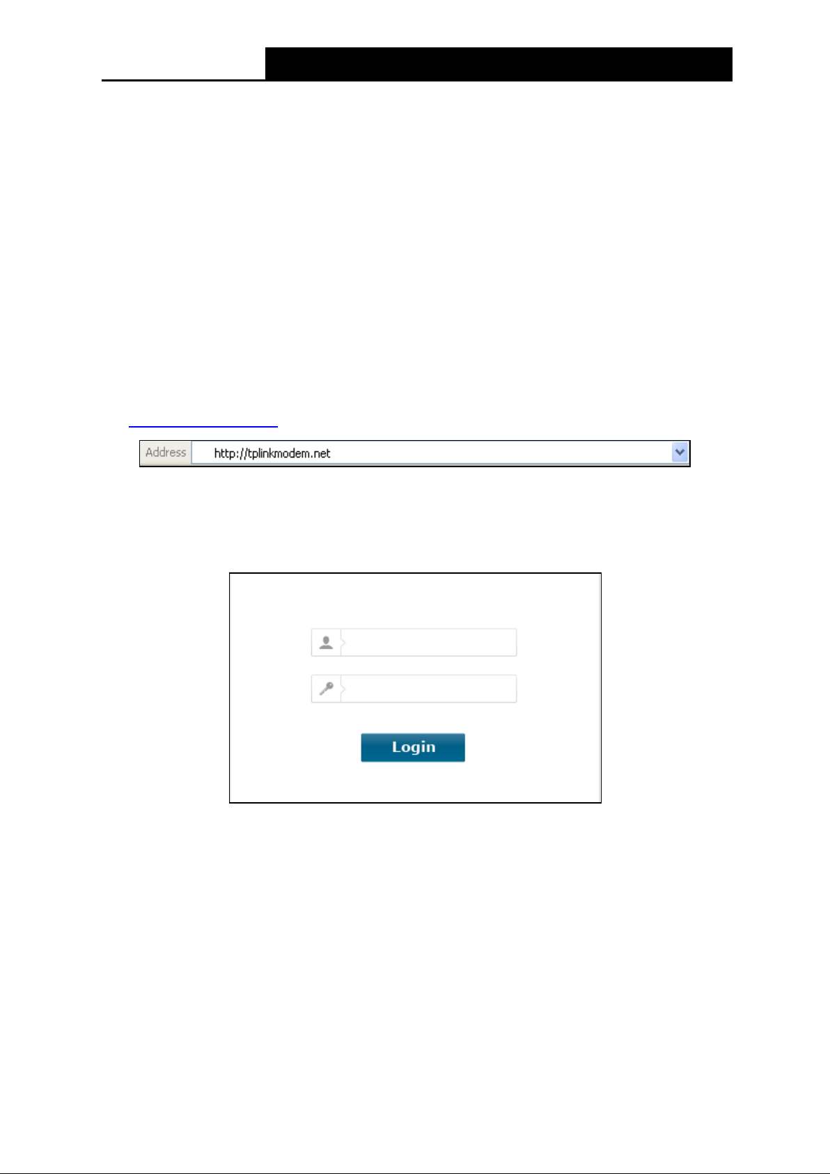
1. To access the configuration utility, open a web-browser and type the default address
http://tplinkmodem.net/
in the address field of the browser.
Figure 3-3
After a moment, a login window will appear, similar to the Figure 3-4. Enter admin for the
Username and Password, both in lower case letters. Then click the Login button or press the
Ente r key.
Figure 3-4
Note:
1) Do not mix up the username and password with your DSL account user name and password
which are needed for PPP connections.
2) If the above screen does not pop up, it means that your Web-browser has been set to a proxy.
Go to Tools menu→Internet Options→Connections→LAN Se tt ings, in the screen that
appears, cancel the Using Proxy checkbox, and click OK to finish it.
2. After your successful login, you will see the Quick Setup screen as shown in Figure 3-5. Click
Next to continue.
10
Page 19
TD-W9970/TD-W9970B
300Mbps Wireless N USB VDSL/ADSL Modem Router User Guide
Figure 3-5
3. Select your Region and Time Zone from the drop-down list, then click Next.
Figure 3-6
4. Select “Ye s” to auto detect your connection type and then click Ne xt . It will take about two
minutes, please wait.
Figure 3-7
5. Configure parameters for WAN connection. Here we take PPPoE as an example. Enter the
username and password provided by your ISP. Click Next.
11
Page 20
TD-W9970/TD-W9970B
300Mbps Wireless N USB VDSL/ADSL Modem Router User Guide
Figure 3-8
6. 3G/4G Router Mode can be set as a backup Internet access method. If you do not want to
configure 3G/4G settings now, just click Next to continue.
Figure 3-9
7. The wireless function is enabled by default. You can rename your wireless network name and
create your own password in this page. The default wireless name is TP-LINK_ XXXX. Click
Next to continue.
Figure 3-10
12
Page 21
TD-W9970/TD-W9970B
300Mbps Wireless N USB VDSL/ADSL Modem Router User Guide
8. On this page, please confirm all parameters. Click Back to modify or click the Save button to
save your configuration.
Figure 3-11
9. You will see the Complete screen below, click Finish to complete these settings.
Figure 3-12
13
Page 22
TD-W9970/TD-W9970B
300Mbps Wireless N USB VDSL/ADSL Modem Router User Guide
Chapter 4. Configuring the Modem Router
This chapter will show each Web page's key function and the configuration.
4.1 Login
After your successful login, you will see the twenty-t wo main menus on the left of the Web-based
management page. On the right, there are the corresponding explanations and instructions.
The detailed explanations for each Web page’s key function are listed below.
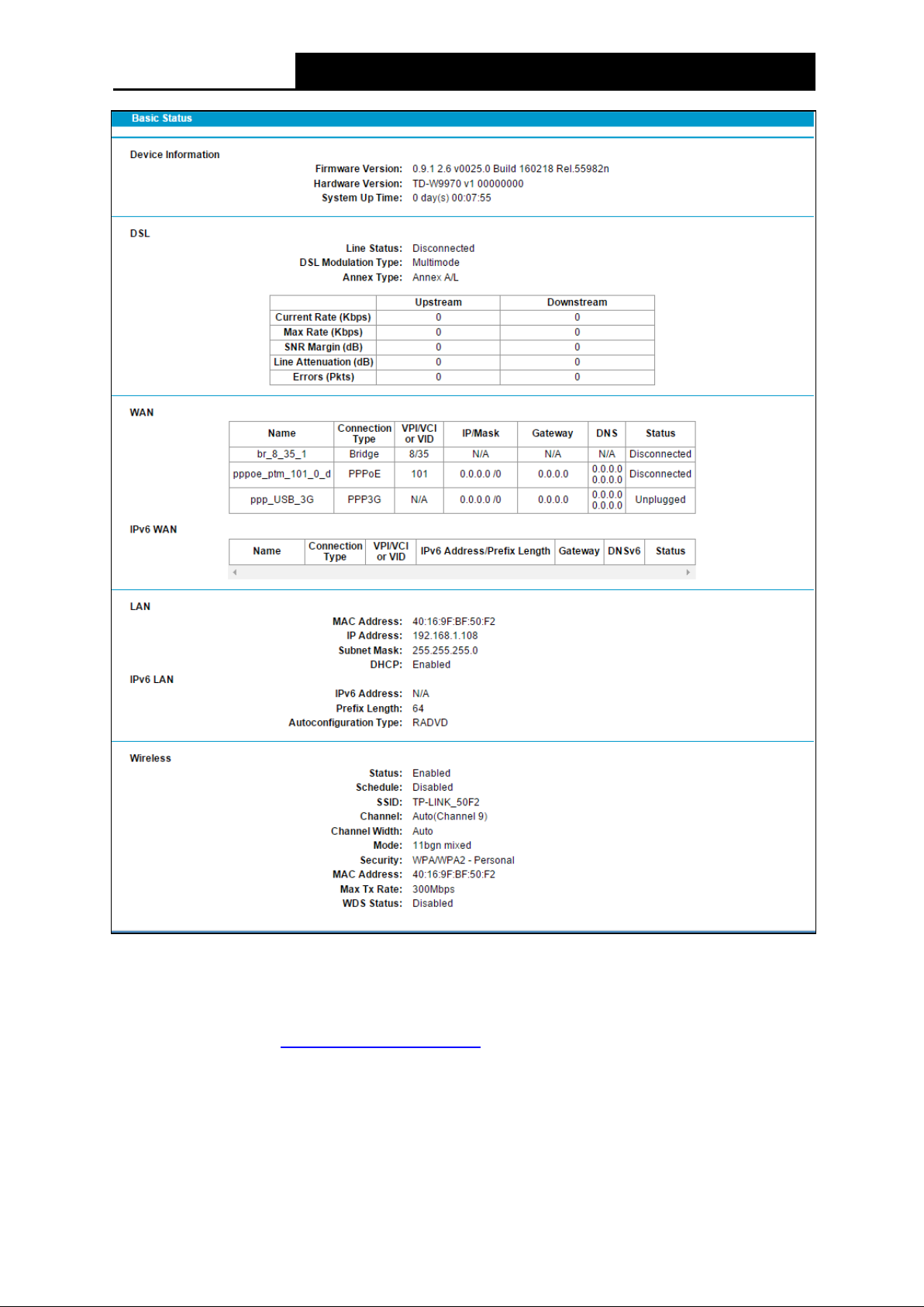
4.2 Statu s
Choose “Stat us”, you can see the corresponding information about Device Informatio n, DSL,
WAN, LAN and Wirele ss.
14
Page 23
TD-W9970/TD-W9970B
300Mbps Wireless N USB VDSL/ADSL Modem Router User Guide
Figure 4-1
4.3 Quick Setup
Please refer to Section 3.2 Quick Installation Guide.
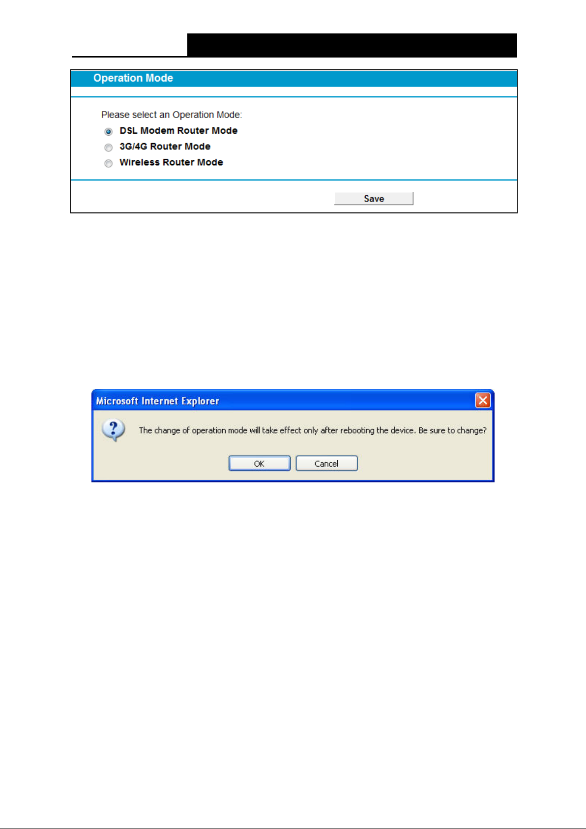
4.4 Operation Mode
Choose “Operation M o de”, and you will see the screen as shown in Figure 4-2. Select your
desired mode and then click Save .
15
Page 24
TD-W9970/TD-W9970B
300Mbps Wireless N USB VDSL/ADSL Modem Router User Guide
Figure 4-2
DSL M odem Router M ode : In this mode, the device enables multi-users to share Internet via
ADSL/VDSL using its VDSL port and share it wirelessly at 300Mbps wireless 802.11n speeds.
3G/4G Router Mode : In this mode, the device allows multi-users to share a 3G/4G mobile
broadband connection via wired or wireless connection.
Wireless Route r Mode : In this mode, the device enables multi-users to share Internet via
Ethernet WAN (EWAN) using its interchangeable LAN/WAN port and share it wirelessly at
300Mbps wireless 802.11n speeds.
After you click the Save button, the Note Dialog will appear. Click OK and then the modem router
will reboot. Please wait.
Note Dialog
4.5 Network
Choose “Ne t work”, there are many submenus under the main menu. Click any one of them, and
you will be able to configure the corresponding function.
16
Page 25
TD-W9970/TD-W9970B
300Mbps Wireless N USB VDSL/ADSL Modem Router User Guide
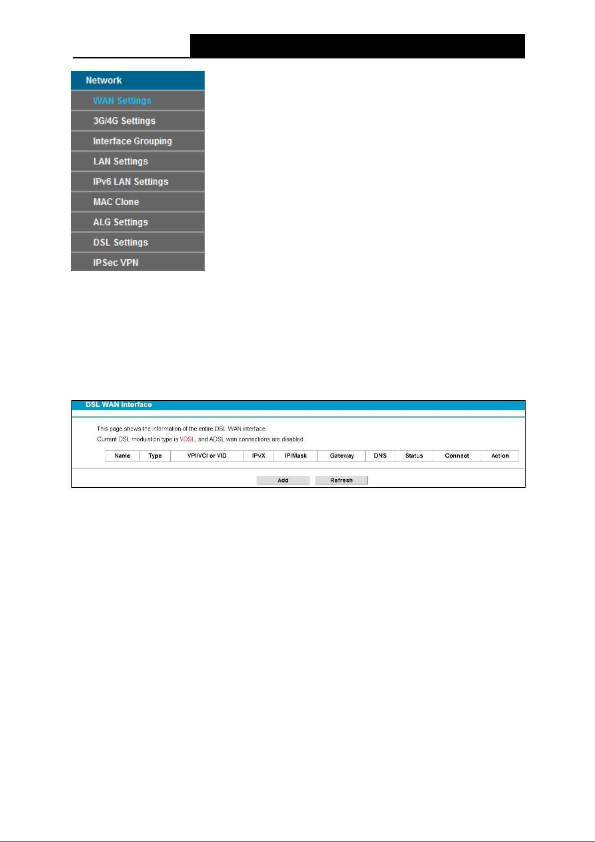
4.5.1 WAN Settings
Choose “Networ k ”“WAN Settings”, and you will see the WAN Port Information Table in the
screen similar to Figure 4-3.
4.5.1.1 VDSL WAN Settings
For VDSL mode, there are four different connection types, which are Static IP, Dynamic IP,
PPPoE and Bridge. You can select the corresponding types according to your needs.
Figure 4-3
Click Ad d to add a new entry, you can configure the parameters for PTM and W AN Service in the
next screen (shown in Figure 4-4).
17
Page 26
TD-W9970/TD-W9970B
300Mbps Wireless N USB VDSL/ADSL Modem Router User Guide
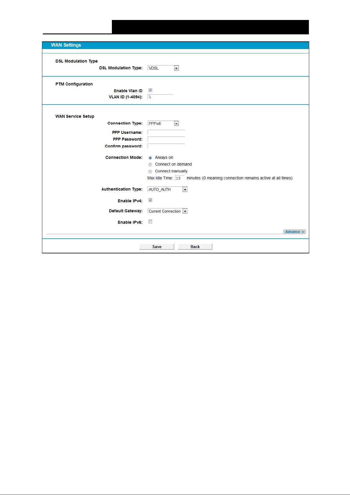
Figure 4-4
DSL Modulation Type:
DSL M odulat ion Type : The modem router supports two modulation types: ADSL and VDSL,
you can select the corresponding types according to your needs.
PTM Configuration:
Enable VLAN ID: Check the box to enable the Virtual LAN ID.
VLAN ID (1~4049): This indicates the VLAN group, and the valid range is from 1 to 4049.
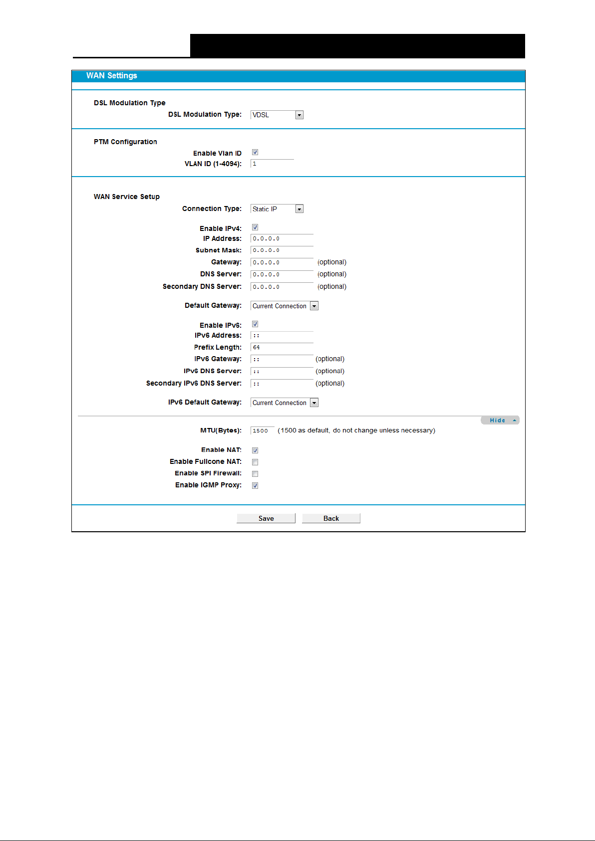
1) Static IP
Select this option if your ISP provides static IP information to you. You should set static IP address,
IP subnet mask, and gateway address in the screen below.
18
Page 27
TD-W9970/TD-W9970B
300Mbps Wireless N USB VDSL/ADSL Modem Router User Guide
:
Figure 4-5
WAN Service Setup:
Enable IPv4
IP Address: Enter the IP address in dotted-decimal notation provided by your ISP.
Subnet Mask: Enter the subnet Mask in dotted-decimal notation provided by your ISP,
Check the box to enable IPv4.
usually is 255.255.255.0.
Gateway (Optional): Enter the gateway IP address in dotted-decimal notation provided by
your ISP.
DNS Se rver/ Secondary DNS Server: Here you can set DNS Server (at least one) manually.
The Route will use this DNS Server for priority.
De fault Gate way: Select a WAN Interface from the drop-down list as the IPv4 default
gateway.
Enable IPv 6: Check the box to enable IPv6.
19
Page 28

TD-W9970/TD-W9970B
300Mbps Wireless N USB VDSL/ADSL Modem Router User Guide
IPv6 Address: Enter the IPv6 address provided by your ISP.
Pre fix Le ngth: Enter the prefix length of the IPv6 address. The default value is 64.
IPv 6 Gate way: Enter the gateway IPv6 address provided by your ISP.
IPv6 DNS Server / Secondary IPv6 DNS Server: Here you can set IPv6 DNS Server ( at
least one) manually. The Route will use this IPv 6 DNS Server for priority.
IPv6 Default Gateway: Select a WAN Interface from the drop-down list as the IPv6 default
gateway.
Click Advance, advanced selections of WAN Service Setup can be shown.
M TU (Byte s): Maximum Transmission Unit Size. Check this box then you can change the
MT U size. The default M TU value is 1500 Bytes. It is not recommended that you change the
default value unless required by your ISP.
Enable NAT: This technology translates the IP addresses of a local area network to a
different IP address for the Internet. If this modem router is hosting your network’s connection
to the Internet, please select the check box. If another Router exists in your network, you don’t
need to select the option.
Enable Fullcone NAT: It is a type of NAT, if not enabled, the default NAT will act.
Enable SPI Firewall: A SPI firewall enhances network’s security. Select the option to use a
firewall, or else without a firewall.
Enable IGM P Pro xy: IGMP (Internet Group Management Protocol) is used to manage
multicasting on TCP/IP networks. Some ISPs use IGMP to perform remote configuration for
client devices, such as the modem router. The default value is disabled, and if you are not
sure, please contact your ISP or just leave it.
Click the Save button to save the settings.
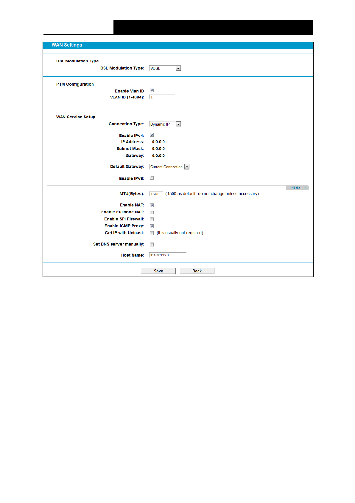
2) Dynamic IP
Select this option, the modem router will be able to obtain IP network information dynamically fro m
a DHCP server provided by your ISP.
20
Page 29
TD-W9970/TD-W9970B
300Mbps Wireless N USB VDSL/ADSL Modem Router User Guide
Figure 4-6
Click Advance, advanced selections for WAN Service Setup can be shown.
M TU (Byte s ): Maximum Transmission Unit Size. Check this box then you can change the
MT U s i ze. The default M TU value is 1500 Bytes. It is not recommended that you change the
default value unless required by your ISP.
Enable NAT: This technology translates the IP addresses of a local area network to a different
IP address for the Internet. If this modem router is hosting your network’s connection to the
Internet, please select the check box. If another Router exists in your network, you don’t need
to select the option.
Enable Fullcone NAT: It is a type of NAT, if not enabled, the default NAT will act.
Enable SPI Firewall: A SP I firewall enhances network’s security. Select the option to use a
firewall, or else without a firewall.
Enable IGM P Proxy: IG MP (Internet Group Management Protocol) is used to manage
multicasting on TCP/IP networks. Some ISPs use IGMP to perform remote configuration for
client devices, such as the modem router. The default value is disabled, and if you are not sure,
please contact your ISP or just leave it.
21
Page 30
TD-W9970/TD-W9970B
300Mbps Wireless N USB VDSL/ADSL Modem Router User Guide
Get IP with Unicast: This is disabled by default. The minority of DHCP Server of ISP will not
support to enable this. When the Route is connected right but IP cannot get, you can select
this box.
Set DNS Server manually: Choose “Set DNS Server manually”, you can set DNS Server
manually here. The modem router will use this DNS Server for priority.
Get IPv6 Address with Unicast: This is disabled by default. The minority of DHCPv6 Server
of ISP will not support to enable this. When the modem router is connected right but cannot
get IPv6 address, you can select this box.
Set IPv6 DNS Server manually: Choose “Set IPv6 DNS Server manually”, you can set IPv6
DNS Server manually here. The modem router will use this IPv6 DNS Server for priority.
Host Name: Here displays model No. of your modem router.
Click the Save button to save the settings.
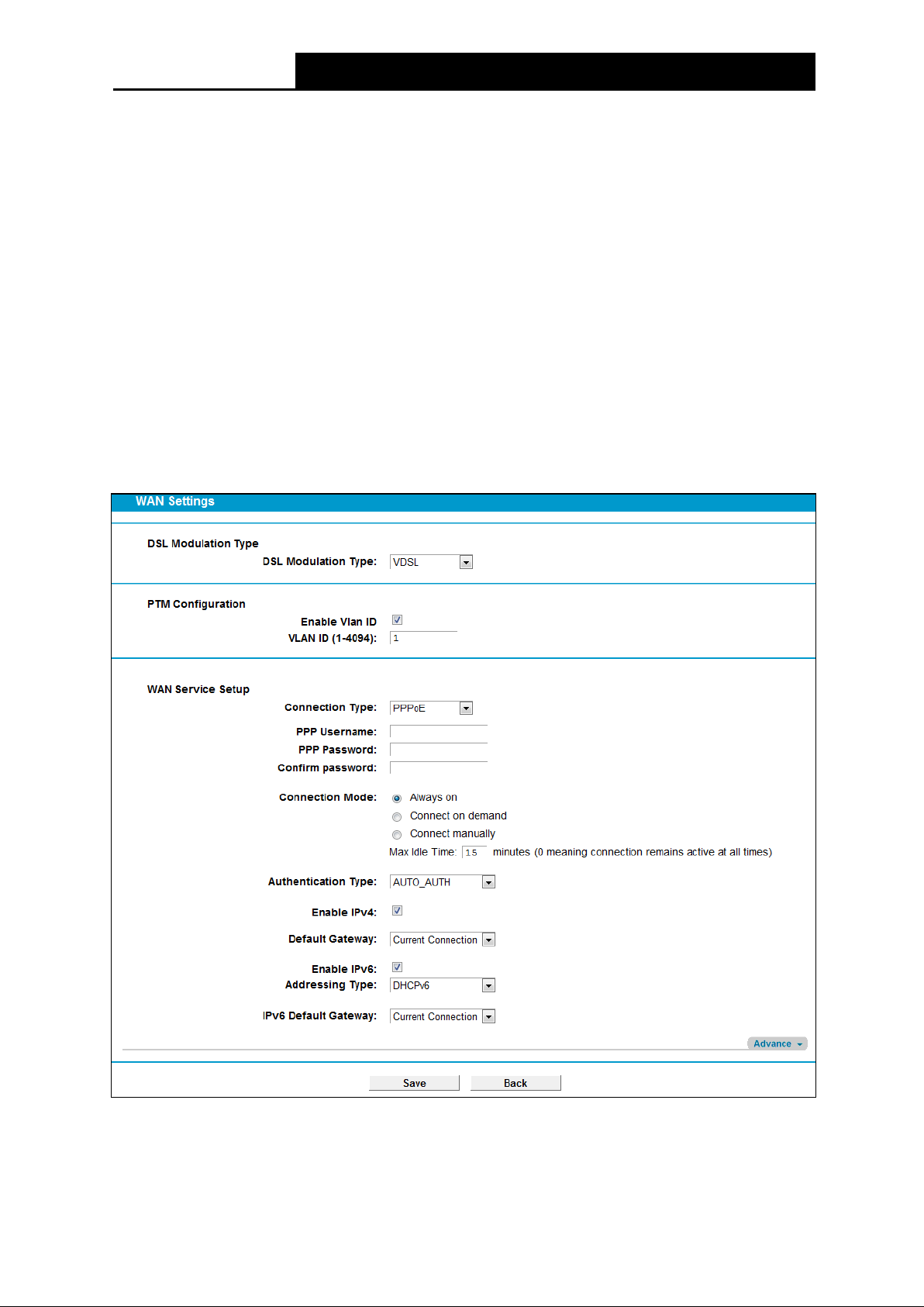
3) PPPoE
If yo ur ISP provides a PPPoE connection and you need to use an ATM Interface, choose PPPoE
in the drop-down list, and then the screen will be displayed as below.
Figure 4-7
PPP Use rname/Password/Con f ir m password: Enter the User Name, Password and
Confirm password provided by your ISP. These fields are case-sensitive.
22
Page 31

TD-W9970/TD-W9970B
300Mbps Wireless N USB VDSL/ADSL Modem Router User Guide
Connection Mode: For PPPoE connection, you can select Always on or Connect on
de mand or Connect manually. Connect on demand is dependent on the traffic. If there is no
traffic (or Id le ) for a pre-specified period of time, the connection will
drop down automatically.
And once there is traffic send or receive, the connection will be automatically on.
Authentication Type : Select the Authentication Type from the drop-down list, the default
method is AUTO_AUTH, and you can leave it as a default setting.
Enable IPv 4: Check this box to enable IPv4.
Enable IPv 6: Check this box to enable IPv6.
De fault Gateway: Select a WAN connection from the drop-down list as the IPv4 default
gateway.
IPv6 Default Gateway: Select a WAN connection from the drop-down list as the IPv6 default
gateway.
Click Advance, advanced selections for WAN Service Setup can be shown.
Se rvice Na me /Server Name: Enter the Service Name and Server Name if it was provided by
your ISP. You can leave them blank, if the ISP doesn’t provide them.
M TU (Byte s): Maximum Transmission Unit Size. Check this box then you can change the
MT U size. The default M TU value is 1500 Bytes. It is not recommended that you change the
default value unless required by your ISP.
Enable Fullcone NAT: It is a type of NAT, if not enabled, the default NAT will act.
Enable SPI Firewall: A SPI firewall enhances network’s security. Select the option to use a
firewall, or else without a firewall.
Enable IGM P Proxy: IGM P (Internet Group Management Protocol) is used to manage
multicasting on TCP/IP networks. Some ISPs use IGMP to perform remote configuration for
client devices, such as the modem router. The default value is disabled, and if you are not
sure, please contact your ISP or just leave it.
Use IP address spe cifie d by ISP: Choose “Use IP address specified by ISP”, you can enter
the IP address provided by your ISP.
Set DNS Server manually: Choose “Set DNS Server manually”, you can set DNS Server
manually here. The modem router will use this DNS Server for priority.
Use IPv6 address spe cified b y ISP: Choose “Use IPv6 address specified by ISP”, you can
enter the IPv6 address provided by your ISP.
Set IPv6 DNS Server manually: Choose “Set IPv6 DNS Server manually”, you can set IPv6
DNS Server manually here. The modem router will use this IPv6 DNS Server for priority.
Click the Save button to save the settings.
4) Bridge
If you select this type of connection, the modem router can be configured to act as a bridging
device between your LAN and your ISP. Bridges are devices that enable two or more networks to
communicate as if they are two segments of the same physical LAN.
23
Page 32

TD-W9970/TD-W9970B
300Mbps Wireless N USB VDSL/ADSL Modem Router User Guide
Figure 4-8
Note:
After you finishing the Internet configuration, please click Sav e to make the settings take effect.
4.5.1.2 ADSL WAN Settings
For ADSL mode, there are six different configurations for the connection types, wh ich are Static IP,
Dynamic IP, PPPo E, PPPoA, IPoA and Bridge. You can select the corresponding types according
to your needs.
Figure 4-9
Click Add to add a new entry, you can configure the parameters for PTM and WAN Service in the
next screen (shown in Figure 4-10).
24
Page 33

TD-W9970/TD-W9970B
300Mbps Wireless N USB VDSL/ADSL Modem Router User Guide
Figure 4-10
DSL Modulation Type:
DSL M odulat ion Type : The modem router supports two modulation types: ADSL and VDSL,
you can select the corresponding types according to your needs.
ATM Configuration:
VPI (0~255): Identifies the virtual path between endpoints in an ATM network. The valid range
is from 0 to 255. Please input the value provided by your ISP.
VCI (1~65535): Identifies the virtual channel endpoints in an ATM network. The valid range is
fr om 1 to 65535 (1 to 31 is reserved for well-known protocols). Please input the value
provided by your ISP.
1) Static IP
Select this option if your ISP provides static IP information to you. You should set static IP address,
IP subnet mask, and gateway address in the screen below.
25
Page 34

TD-W9970/TD-W9970B
300Mbps Wireless N USB VDSL/ADSL Modem Router User Guide
:
Figure 4-11
Click Advance, advanced selections of ATM Configuration can be shown.
Encapsulation Mode : Select the encapsulation mode for the Static IP Address. He r e you
can leave it default.
ATM Q o s Type: Select ATM Qos Type provided by ISP, and the type is UBR by default.
WAN Service Setup:
Enable IPv4
IP Address: Enter the IP address in dotted-decimal notation provided by your ISP.
Check the box to enable IPv4.
26
Page 35

TD-W9970/TD-W9970B
300Mbps Wireless N USB VDSL/ADSL Modem Router User Guide
Subnet Mask: Enter the subnet Mask in dotted-decimal notation provided by your ISP,
usually is 255.255.255.0.
Gateway (Optional): Enter the gateway IP address in dotted-decimal notation provided by
your ISP.
DNS Server/ Secondary DNS Server: Here you can set DNS Server (at least one) manually.
The Route will use this DNS Server for priority.
De fault Gate way: Select a WAN Interface from the drop-down list as the IPv4 default
gateway.
Enable IPv 6: Check the box to enable IPv6.
IPv6 Address: Enter the IPv6 address provided by your ISP.
Pre fix Le ngth: Enter the prefix length of the IPv6 address. The default value is 64.
IPv6 Gateway: Enter the gateway IPv6 address provided by your ISP.
IPv 6 DNS Server / Se condary IPv6 DNS Server: Here you can set IPv6 DNS Server (at
least one) manually. The Route will use this IPv6 DNS Server for priority.
IPv6 Default Gateway: Select a WAN Interface from the drop-down list as the IPv6 default
gateway.
Click Advance, advanced selections of WAN Service Setup can be shown.
M TU (Byte s): Maximum Transmission Unit Size. Check this box then you can change the
MT U size. The default M TU value is 1500 Bytes. It is not recommended that you change the
default value unless required by your ISP.
Enable NAT: This technology translates the IP addresses of a local area network to a
different IP address for the Internet. If this modem router is hosting your network’s connection
to the Internet, please select the check box. If another Router exists in your network, you don’t
need to select the option.
Enable Fullcone NAT: It is a type of NAT, if not enabled, the default NAT will act.
Enable SPI Firewall: A SPI firewall enhances network’s security. Select the option to use a
firewall, or else without a firewall.
Enable IGM P Pro xy: IGMP (Internet Group Management Protocol) is used to manage
multicasting on TCP/IP networks. Some ISPs use IGMP to perform remote configuration for
client devices, such as the modem router. The default value is disabled, and if you are not
sure, please contact your ISP or just leave it.
Click the Save button to save the settings.
2) Dynamic IP
Select this option, the modem router will be able to obtain IP network information dynamically fr om
a DHCP server provided by your ISP.
27
Page 36

TD-W9970/TD-W9970B
300Mbps Wireless N USB VDSL/ADSL Modem Router User Guide
Figure 4-12
Click Advance, advanced selections for WAN Service Setup can be shown.
M TU (Byte s): Maximum Transmission Unit Size. Check this box then you can change the
MT U s i ze. The default M TU value is 1500 Bytes. It is not recommended that you change the
default value unless required by your ISP.
28
Page 37

TD-W9970/TD-W9970B
300Mbps Wireless N USB VDSL/ADSL Modem Router User Guide
Enable NAT: This technology translates the IP addresses of a local area network to a different
IP address for the Internet. If this modem router is hosting your network’s connection to the
Internet, please select the check box. If another Router exists in your network, you don’t need
to select the option.
Enable Fullcone NAT: It is a type of NAT, if not enabled, the default NAT will act.
Enable SPI Firewall: A SPI firewall enhances network’s security. Select the option to use a
firewall, or else without a firewall.
Enable IGM P Proxy: IG MP (Internet Group Management Protocol) is used to manage
multicasting on TCP/IP networks. Some ISPs use IGMP to perform remote configuration for
client devices, such as the modem router. The default value is disabled, and if you are not sure,
please contact your ISP or just leave it.
Get IP with Unicast: This is disabled by default. The minority of DHCP Server of ISP will not
support to enable this. When the Route is connected right but IP cannot get, you can select this
box.
Set DNS Server manually: Choose “Set DNS Server manually”, you can set DNS Server
manually here. The modem router will use this DNS Server for priority.
Get IPv6 Address with Unicast: This is disabled by default. The minority of DHCPv6 Server
of ISP will not support to enable this. When the modem router is connected right but IPv6
address cannot get, you can select this box.
Set IPv6 DNS Server manually: Choose “Se t IPv6 DNS Server manually”, you can set IPv6
DNS Server manually here. The modem router will use this IPv6 DNS Server for priority.
Host Name: Here displays model No. of your modem router.
Click the Save button to save the settings.
3) PPPoE
If yo ur ISP provides a PPPoE connection and you need to use an ATM Interface, choose PPPoE
in the drop-down list, and then the screen will be displayed as below.
29
Page 38

TD-W9970/TD-W9970B
300Mbps Wireless N USB VDSL/ADSL Modem Router User Guide
Figure 4-13
PPP Use rname/Password/Confirm Password: Enter the User Name, Password and
Confirm Password provided by your ISP. These fields are case-sensitive.
Connection Mode: For PPPoE connection, you can select Always on or Connect on
de mand or Connect manually. Connect on demand is dependent on the traffic. If there is no
traffic (or Idle ) for a pre-specified period of time, the connection will tear down automatically.
And once there is traffic send or receive, the connection will be automatically on.
Authentication Typ e : Select the Authentication Typ e from the drop-down list, the default
method is AUTO_AUTH, and you can leave it as a default setting.
Enable IPv 4: Check this box to enable IPv4.
De fault Gateway: Select a WAN connection from the drop-down list as the IPv4 default
gateway.
Enable IPv 6: Check this box to enable IPv6.
Addressing Type: Select the Addressing Type from the drop-down list.
30
Page 39

TD-W9970/TD-W9970B
300Mbps Wireless N USB VDSL/ADSL Modem Router User Guide
IPv6 Default Gateway: Select a WAN connection from the drop-down list as the IPv6 default
gateway.
Click Advance, advanced selections for WAN Service Setup can be shown.
Service Name /Server Name: Enter the Service Name and Server Name if it was provided by
your ISP. You can leave them blank, if the ISP doesn’t provide them.
M TU (Byte s): Maximum Transmission Unit Size. Check this box then you can change the
MT U size. The default M TU value is 1500 Bytes. It is not recommended that you change the
default value unless required by your ISP.
Enable Fullcone NAT: It is a type of NAT, if not enabled, the default NAT will act.
Enable SPI Firewall: A SPI firewall enhances network’s security. Select the option to use a
firewall, or else without a firewall.
Enable IGM P Proxy: IGM P (Internet Group Management Protocol) is used to manage
multicasting on TCP/IP networks. Some ISPs use IGMP to perform remote configuration for
client devices, such as the modem router. The default value is disabled, and if you are not
sure, please contact your ISP or just leave it.
Use IP address spe cifie d by ISP: Choose “Use IP address specified by ISP”, you can enter
the IP address provided by your ISP.
Echo request interval: The router will detect Access Concentrator online at every inter val.
The default value is “0”. You can input the value between “0” and “120”. The value “0” means
no detect.
Set DNS Server manually: Choose “Set DNS Server manually”, you can set DNS Server
manually here. The modem router will use this DNS Server for priority.
Use IPv6 address spe cified b y ISP: Choose “Use IPv6 address specified by ISP”, you can
enter the IPv6 address provided by your ISP.
Set IPv6 DNS Server manually: Choose “Set IPv6 DNS Server manually”, you can set IPv6
DNS Server manually here. The modem router will use this IPv6 DNS Server for priority.
Click the Save button to save the settings.
4) PPPoA
If yo ur ISP provides a PPPoA connection and you need to use an ATM Interface, choose PPPoA
in the drop-down list, and then the screen will be displayed as below.
The configuration is similar to PPPo E. Please refer to the section 3) PPPoE to configure this part.
31
Page 40

TD-W9970/TD-W9970B
300Mbps Wireless N USB VDSL/ADSL Modem Router User Guide
Figure 4-14
5) IPo A
If yo ur ISP provides an IPoA connection, select IPoA option for the Connection Type on the
screen.
32
Page 41

TD-W9970/TD-W9970B
300Mbps Wireless N USB VDSL/ADSL Modem Router User Guide
Figure 4-15
IP Address/Subne t M ask: Enter the IP Address and Subnet Mask provided by ISP. If you
forget, you can ask your ISP.
Gateway: Enter the gateway IP address in dotted-decimal notation provided by your ISP.
DNS Server/ Se condary DNS Se rver: Type in your preferred DNS server.
De fault Gate way: Select a WAN Interface from the drop-down list as the IPv4 default
gateway.
6) Bridge
If you select this type of connection, the modem router can be configured to act as a bridging
device between your LAN and your ISP. Bridges are devices that enable two or more networks to
communicate as if they are two segments of the same physical LAN.
33
Page 42

TD-W9970/TD-W9970B
300Mbps Wireless N USB VDSL/ADSL Modem Router User Guide
Figure 4-16
Note:
After you finishing the Internet configuration, please click Sav e to make the settings take effect.
4.5.2 3G/4G Settings
If your modem router is in 3G/4G Router Mode, choose menu “Ne t wo rk→3G/4G Settings”, you
can configure parameters for 3G/4G function on the screen below. To use the 3G/4G function, you
should first insert your USB modem on the USB port of the modem router. There is already much
3G/4G USB modem information embedded in the modem router. If your USB modem is supported
by the modem router, then “Succe ssfully Identif ie d” will display in the USB 3G/4G Modem field.
Select the correct Location and M o b ile ISP manually, the USB modem parameters will be set
automatically.
Some 3G/4G USB modem may not be supported by the modem router. For more information,
please refer to Compatibility List on our website: www. t p -link.com
incompatible with our modem router, please contact our technical support by referring to the
Technical Support card found in your package.
. If your 3G/4G USB modem is
34
Page 43

TD-W9970/TD-W9970B
300Mbps Wireless N USB VDSL/ADSL Modem Router User Guide
Figure 4-17
Location: Please select the location where you're enjoying the 3G/4G card.
Mobi le ISP: Please select the ISP (Internet Service Provider) you apply to for 3G/4G service.
The modem router will show the default Dial Number and APN of that ISP.
Set the Dial Number, APN, Username and Password manually: Check the box and fill the
Dial Number and APN blanks below if your ISP is not listed in the Mob i le ISP list or the default
values are not the latest ones.
Dial Numbe r: Enter the Dial Number provided by your ISP.
APN: Enter the APN (Access Point Name) provided by your ISP.
Username/Password: Enter the Username and Password provided by your ISP. These fields
are case-sensitive.
Always on: Connect automatically after the modem router is disconnected. This option is
enabled by default.
Connect on demand: Connect on demand is dependent on the traffic. If there is no traffic (or
Idle ) for a pre-specified period of time (Max Id le Time ), the connection will tear down
automatically. And once there is traffic send or receive, the connection will be automatically on.
If you want your Internet connection to remain active at all times, enter 0 in the M ax Idle Time
field.
Note:
Sometimes the connection cannot be disconnected although you specify a time to Max Idle
Time because some applications visit the Internet continually in the background.
Connect manually: You can click the Connect/Disconnect button to connect/disconnect
connection immediately. This mode also supports the M ax Idle Time function as Connect on
de mand mode. If you want your Internet connection to remain active at all times, enter 0 in the
Max Idle Time field.
Authentication Type : Some ISPs need a specific authentication type, please confirm it with
your ISP or keep the default settings.
35
Page 44

TD-W9970/TD-W9970B
300Mbps Wireless N USB VDSL/ADSL Modem Router User Guide
Click Advance in Figure 4-17 to configure advanced settings for 3G/4G Setup.
Figure 4-18
MTU size (in byte s) : The default MTU (Maximum Transmission Unit) size is 1480 bytes,
which is usually fine. For some ISPs, you need modify the MTU. This should not be done
unless you are sure it is necessary for your ISP.
Echo request interval: The router will detect Access Concentrator online at every interva l.
The default value is “0”. You can input the value between “0” and “120”. The value “0” means
no detect.
Use the fo llo wing IP Address: If your ISP specifies an IP address for you, check the box,
and fill the Static IP Address.
Use the following DNS Servers: If your ISP specifies a DNS server IP address for you, check
the box, and fill the Primary DNS and Se co nd ary DNS blanks below. The Secondary DNS is
optional. Otherwise, the DNS servers will be assigned dynamically from ISP.
Primary DNS: Enter the DNS IP address in dotted-decimal notation provided by your ISP.
Se condary DNS: (Optional) Enter another DNS IP address in dotted-decimal notation
provided by your ISP.
Click the Sav e button to save your settings.
Once the connection is successful, click menu Status and you will see the 3G/4G status is similar
to Figure 4-19.
Figure 4-19
Note:
After connecting a 4G modem to the modem router, please access the Web-based
management page by typing http://tplinkmodem.net
press Enter.
4.5.3 Interface Grouping
Choose “Ne t w ork”“Interface Grouping”, you can view all the current groups on this page
(shown in Figure 4-20).
36
/ in the address field of the browser and
Page 45

TD-W9970/TD-W9970B
300Mbps Wireless N USB VDSL/ADSL Modem Router User Guide
Figure 4-20
Enable the Virtual LAN Ports feature: Virtual LAN (VLAN) is a group of devices on one or
more LANs that are configured so that they can communicate as if they were attached to the
same LAN. Because VLANs are based on logical instead of physical connections, it is very
flexible for user/host management, bandwidth allocation and resource optimization. If you
want to active Interface Grouping function, please check the box to enable the Virtual LAN
Ports feature.
Note:
It is not allowed to disable the VLAN with Ethernet Connection enabled.
To support this feature, you must create mapping groups with appropriate LAN and WAN
interfaces using the Ad d button. The Re move button will remove the grouping and add the
ungrouped interfaces to the Default group. Only the default group has IP interface.
Click the Add button. You can add a new interface group in the next screen. For example, you
want LAN1 and LAN3 to be a group called Group 1 over br_ptm_1_0 WAN interface, you can refer
to the following figure.
37
Page 46

TD-W9970/TD-W9970B
300Mbps Wireless N USB VDSL/ADSL Modem Router User Guide
Figure 4-21
Click Save to make the entry effective immediately
4.5.4 LAN Settings
Choose “Ne t w ork”“LAN Settings” menu, and you will see the LAN screen (shown in Figure
4-22). Please configure the parameters for LAN ports according to the descriptions below.
38
Page 47

TD-W9970/TD-W9970B
300Mbps Wireless N USB VDSL/ADSL Modem Router User Guide
Figure 4-22
IP Address: You can configure the modem router’s IP Address and Subnet Mask for LAN
Interface.
• IP Address: Enter the modem router’s local IP Address, then you can access to the
Web-based management page via the IP Address, the default value is 192.168.1.1.
• Subnet Mask: Enter the modem router’s Subnet Mask, the default value is 255.255.255.0.
Enable IGMP Snooping: If you select the option, please choose the IGMP Mode: Standard
Mode or Blocking Mode.
Enable Second IP: You can configure the modem router’s second IP Address and Subnet
Mask for LAN Interface through which you can also access to the Web-based management
page as the default IP Address and Subnet Mask.
DHCP Server: These settings allow you to configure the modem router‘s Dynamic Host
Configuration Protocol (DHCP) server function. The DHCP server is enabled by default for the
modem router’s Ethernet LAN interface. DHCP service will supply IP settings to computers
which are configured to automatically obtain IP settings that are connected to the modem
router though the Ethernet port. When the modem router is set for DHCP, it becomes the
default gateway for DHCP client connected to it. Keep in mind that if you change the IP
address of the modem router, you must change the range of IP addresses in the pool used for
DHCP on the LAN.
• Start IP Address: Enter a value for the DHCP server to start with when issuing IP
addresses. Because the default IP address for the modem router is 192.168.1.1, the
default Start IP Address is 192.168.1.100, and the Start IP Address must be 192.168.1.100
or greater, but smaller than 192.168.1.254.
• End IP Address: Enter a value for the DHCP server to end with when issuing IP
addresses. The End IP Address must be smaller than 192.168.1.254. The default End IP
Address is 192.168.1.254.
39
Page 48

TD-W9970/TD-W9970B
300Mbps Wireless N USB VDSL/ADSL Modem Router User Guide
• Le ased Time : The Leased Time is the amount of time in which a network user will be
allowed connection to the modem router with their current dynamic IP address. Enter the
amount of time, in hours, then the user will be “leased” this dynamic IP address. After the
dynamic IP address has expired, the user will be automatically assigned a new dynamic IP
address. The default is 1440 minutes.
The detailed configuration about DHCP server, please refer to section 4.7 DHCP Server
.
4.5.5 IPv6 LAN Settings
Choose menu “Ne t wo rk”“IPv6 LAN Settings”, you can configure LAN IPv6 interface for your
modem router.
Figure 4-23
Address Auto-configuration Type : Select a typ e to assign IPv6 addresses to the computers
in your LAN. RADVD and DHCPv6 Server are provided.
1) If RADVD is selected, it doesn’t need to be configured.
2) If DHCPv6 Server is selected, please complete the following parameters.
40
Page 49

TD-W9970/TD-W9970B
300Mbps Wireless N USB VDSL/ADSL Modem Router User Guide
Figure 4-24
• Start IPv6 Address: Enter a value for the DHCPv6 server to start with when issuing IPv6
addresses.
• End IPv6 Address: Enter a value for the DHCPv6 server to end with when issuing IPv6
addresses.
• Le ased Time : The Leased Time is the amount of time in which a network user will be
allowed connection to the modem router with their current dynamic IPv6 address. Enter
the amount of time, in hours, then the user will be “leased” this dynamic IPv6 address.
After the dynamic IPv6 address has expired, the user will be automatically assigned a
new dynamic IPv6 address. The default is 86400 seconds.
Sit e Pre fix Configu ration Type : Select a type to assign prefix to IPv6 addresses. Delegated
and Static are provided.
1) If Delegated is selected, please complete the following parameters.
Figure 4-25
• Prefix Delegated WAN Connection: Select a WAN connection form the drop-down list
to assign prefix.
2) If Static is selected, please complete the following parameters.
Figure 4-26
41
Page 50

TD-W9970/TD-W9970B
300Mbps Wireless N USB VDSL/ADSL Modem Router User Guide
• Site Pre fix: Enter a value for the site prefix.
• Site Prefix Length: Enter a value for the site prefix length.
Click the Sav e button to save the settings.
4.5.6 MAC Clone
Choose menu “Ne two r k”“M AC Clone”, you can configure the MAC address of the WAN
Interface as shown below.
The WAN Interface List displays the WAN Interfaces you have configured on the section
WAN Settings and its default MAC Address. You can select corresponding WAN Interface from the
drop-down list and click Clone M AC To button to clone your current PC MAC, and then click
Sav e .
Figure 4-27
Note:
Only the WAN Ports can use MAC Address Clone function. All the clone MAC addresses must not
be the same with each other.
4.5.1
4.5.7 ALG Settings
Choose menu “Ne two r k”“ALG Se ttings”, and then you can configure the basic secur ity in the
screen as shown in Figure 4-28.
42
Page 51

TD-W9970/TD-W9970B
300Mbps Wireless N USB VDSL/ADSL Modem Router User Guide
Figure 4-28
Virtual Private Network (VPN): VPN Passthrough must be enabled if you want to allow VPN
tunnels using VPN protocols to pass through the modem router.
• PPTP Passthrough: Point-to-Point Tunneling Protocol (PPTP) allows the Point-to -Point
Protocol (PPP) to be tunneled through an IP network. To allow PPTP tunnels to pass
through the modem router, click Enable.
• L2TP Passthrough: Layer Two Tunneling Protocol (L2TP) is the method used to
enable Point-to-Point sessions via the Internet on the Layer Two level. To allow L2TP
tunnels to pass through the modem router, click Enable.
• IPSec Passthrough: Internet Protocol security (IPSec) is a suite of protocols for
ensuring private, secure communications over Internet Protocol (IP) networks, through
the use of cryptographic security services. To allow IPSec tunnels to pass through the
modem router, click Enable.
Application Layer Gateway (ALG): It is recommended to enable Application Layer Gateway
(ALG) because ALG allows customized Network Address Translation (NAT) traversal filters to
be plugged into the gateway to support address and port translation for certain application
layer "control/data" protocols such as FTP, TFTP etc.
• F TP ALG: To allow FTP clients and servers to transfer data across NAT, click Enable.
• TFTP ALG: To allow TFTP clients and servers to transfer data across NAT, click Enable.
• H323 ALG: To allow H323 clients and servers to transfer data across NAT, click Enable.
• SIP ALG: To allow SIP clients and servers to transfer data across NAT, click Enable.
Click the Save button to save your settings.
43
Page 52

TD-W9970/TD-W9970B
300Mbps Wireless N USB VDSL/ADSL Modem Router User Guide
4.5.8 DSL Settings
Choose “Networ k ”“DSL Se tting s”, you can select the DSL Modulation Type and Annex Type in
the next screen. The DSL feature can be selected when you meet the physical connection
problem. Please check the proper settings with your Internet service provider.
Figure 4-29
DSL M odulation Type: Select the DSL operation Modulation Type which your DSL
connection uses.
Annex Type : Select the DSL operation Annex Type which your DSL connection uses.
Click the Save button to save your settings.
4.5.9 IPSec VPN
Choose “Ne twor k ”“IPSec VPN”, you can Add/Remove or Enable/Disable the IPSec tunnel
connections on the screen as shown in Figure 4-30.
Figure 4-30
This section will guide you to configure a VPN tunnel between two modem routers. The topology is
as follows.
44
Page 53

TD-W9970/TD-W9970B
300Mbps Wireless N USB VDSL/ADSL Modem Router User Guide
Note:
You could also use other VPN Routers to set VPN tunnels with the modem router. It supports u p to
10 VPN tunnels simultaneously.
Click Add New Connection in Figure 4-30 and then you will enter the screen shown in Figure
4-31.
45
Page 54

TD-W9970/TD-W9970B
300Mbps Wireless N USB VDSL/ADSL Modem Router User Guide
Figure 4-31
IPSec Connection Name: Enter a name for your VPN.
Remote IPSe c Gate way Address (URL): Enter the destination gateway IP address in the box
which is the public WAN IP or Domain Name of the remote VPN server endpoint. (For example:
Input 219.134.112.247 in Device1, Input 219.134.112.246 in Device 2)
Tunnel access from local IP addresses: Choose Subnet if you want the Whole LAN to join
the VPN network, or else choose Single Address if you want single IP to join the VPN network.
IP Address for VPN: Enter the IP address of your LAN. (For example: Input 192.168.1.1 in
Dev ice1, Input 192.168.2.1 in Device2)
IP Subnetmask: Enter the Subnet mask of your LAN. ( For example: Input 255.255.255.0 in
both Device1 and Device2)
Tunnel access from remote IP addresses: Choose Subnet if you want the Remote Whole
LAN to join the VPN network, or else choose Single Address if you want single IP to join the
VPN network.
IP Address for VPN: Enter the IP address of the Remote LAN. (For example: Input
192.168.2.1 in Device1,Input 192.168.1.1 in Device2)
IP Subnetmask: Enter the subnetmask of the remote LAN. ( For example: Input
255.255.255.0 in both Device1 and Device2)
Ke y Exchange Method: Select Aut o (IKE) or Manual.
If you select Auto as Key Exchange Method, the screen will display as follows:
46
Page 55

TD-W9970/TD-W9970B
300Mbps Wireless N USB VDSL/ADSL Modem Router User Guide
Figure 4-32
Authentication Method: Select Pre-Shared Key (recommended).
Pre-Sh are d Ke y: Enter the Pre-shared Key for IKE authentication, and ensure both the two
peers use the same key. The key should consist of visible characters without blank space.
Pe rf e ct F o r ward Se cre cy: PFS is an additional security protocol.
We recommend you le ave the Advanced Settings as default value.
After complete the basic settings and click Save/Apply in both Device1 and Device2, PCs in
LAN1 could communicate with PCs in remote LAN2. (For example: You can ping the IP
address of PC2 which is 192.168.2.100 in PC1)
Note:
The VPN Servers Endpoint from both ends must use the same pre-shared keys and Perfect
Forward Secrecy settings.
Click Show Advanced Settings and then you can configure the Advanced Settings.
Figure 4-33
47
Page 56

TD-W9970/TD-W9970B
300Mbps Wireless N USB VDSL/ADSL Modem Router User Guide
Settings for Phase 1:
Mo de : You can select M ain or Aggressive. Select Main to configure the standard negotiation
parameters for IKE phase1. Select Aggressive to configure IKE phase1 of the VPN Tunnel to
carry out negotiation in a shorter amount of time. (Not Recommended-Less Secure)
Note:
The difference between the two is that aggressive mode will pass more information in fewer
packets, with the benefit of slightly faster connection establishment, at the cost of transmitting the
identities of the security firewall in the clear. When using aggressive mode, some configuration
parameters such as Diffie-Hellman groups, and PFS cannot be negotiated, resulting in a greater
importance of having "compatible" configuration on both ends.
M y I dentifier Type - Select the local ID type for IKE negotiation. Local Wan IP: uses an IP
address as the ID in IKE negotiation. FQDN: uses a name as the ID.
M y Ide ntifier - This field does not need to enter if Local WAN IP is selected in My Identifier
Type field. And the WAN IP will be used automatically as Identifier. If Name type is selected,
enter a name for the local device as the ID in IKE negotiation.
Re mote Identifier Type - The remote gateway IP will be inputted automatically if IP Address
type is selected. If Name type is selected, enter the name of the remote peer as the ID in IKE
negotiation.
Re mote Ide ntif ier - This field does not need to enter if Re mote WAN IP is selected in Re mote
Ide ntifier Type field. And the remote gateway IP will be used automatically as Identifier. If
Name type is selected, enter the name of the remote peer as the ID in IKE negotiation.
Encryption Algorithm - Specify the encryption algorithm for IKE negotiation. Options include:
DES, 3DES, AES-128, AES-192, AES-256.
Integrity Algorithm - Select the authentication algorithm for IKE negotiation. Options include:
MD5 and SH A1 .
Se le ct Di f fie -Hellman Group for Key Exchange - Select the DH (Diffie-Hellman) group to be
used in key negotiation phase 1. The DH Group sets the strength of the algorithm in bits.
Key Life Time: Enter the number of seconds for the IPSec lifetime. It is the period of time to
pass before establishing a new IPSec security association (SA) with the remote endpoint. The
default value is 3600.
Settings for Phase 1:
Encryption Algorithm - Specify the encryption algorithm for IKE negotiation. Options include:
DES,3DES, AES-128, AES-192, AES-256
Integrity Algorithm - Select the authentication algorithm for IKE negotiation. Options include:
MD5 and SH A1 .
Diffie-Hellman Group for Ke y Exchange - Select the DH (Diffie-Hellman) group to be used in
key negotiation phase 1. The DH Group sets the strength of the algorithm in bits.
Ke y Life Time - Enter the number of seconds for the IPSec lifetime. It is the period of time to
pass before establishing a new IPSec security association (SA) with the remote endpoint. The
default value is 3600.
48
Page 57

TD-W9970/TD-W9970B
300Mbps Wireless N USB VDSL/ADSL Modem Router User Guide
Note:
If you want to change the default settings of Advanced Settings, please make sure that both VPN
server endpoints use the same Encryption Algorithm, Integrity Algorithm, Diffie-Hellman Group
and Key Life time in both phase1 and phase2.
If you select M anual as Key Exchange M ethod, the screen will display as follows:
Encryption Algorithm - Specify the encryption algorithm. Options include: DES, 3DES, AES
(aes-cbc).
Figure 4-34
Encryption Ke y - Place the mouse in this field about 2s,the requirements of the Encryption
Key will be displayed automatically. Enter the Encryption Key, and ensure both the two peers
use the same key.
Authentication Algorithm - Select the authentication algorithm. Options include: MD5 and
SH A1 .
Authentication Ke y - Place the mouse in this field about 2s,the requirements of the
Authentication Key will be displayed automatically. Then enter the authentication Key.
SPI – Specify the SPI (Security Parameter Index) manually. The SPI here must match the SPI
value at the other end of the tunnel, and vice versa.
4.6 IPT V
Choose “IPTV”, and you will see the screen as shown in Figure 4-35.
49
Page 58

TD-W9970/TD-W9970B
300Mbps Wireless N USB VDSL/ADSL Modem Router User Guide
Figure 4-35
Enable IPTV: Check the box to enable IPTV function.
Enable a wireless connection for IPTV: If enabled, the s et-top box can connect wirelessly
to the modem router. To use this function, follow the steps below:
1. Select Enable IPTV.
2. Select Enable a wire less connection for IPTV.
3. Enable SSID2 or SSID3 for IPTV connection and click Sav e . You may rename the
SSID.
4. Select your desired wireless network for IPTV connection.
DSL M odulat ion Type : The modem router supports two modulation types: ADSL and VDSL,
you can select the corresponding types according to your needs.
50
Page 59

TD-W9970/TD-W9970B
300Mbps Wireless N USB VDSL/ADSL Modem Router User Guide
If you choose "ADSL", you will see the screen as shown in the following figure:
• VPI (0~255): Identifies the virtual path between endpoints in an ATM network. The valid
range is from 0 to 255. Please input the value provided by your ISP.
• VCI (1~65535): Identifies the virtual channel endpoints in an ATM network. The valid range
is from 1 to 65535 (1 to 31 is reserved for well-known protocols). Please input the value
provided by your ISP.
If you choose "VDSL", you will see the screen as shown in the following figure:
• VLAN : Check the box to enable the Virtual LAN ID.
• VLAN ID (1~4049): This indicates the VLAN group, and the valid range is from 1 to 4049.
Click the Save button to save your settings.
4.7 DHCP Server
Choose “DHCP Server”, you can see the next submenus:
Click any of them, and you will be able to configure the corresponding function.
4.7.1 DHCP Settings
Choose menu “DHCP Server”“DHCP Se ttings”, you can configure the DHCP Server on the
page as shown in Figure 4-36.The modem router is set up by default as a DHCP (Dynamic Host
Configuration Protocol) server, which provides the TCP/IP configuration for all the PC(s) that are
connected to the modem router on the LAN.
51
Page 60

TD-W9970/TD-W9970B
300Mbps Wireless N USB VDSL/ADSL Modem Router User Guide
Figure 4-36
Start IP Address: Enter a value for the DHCP server to start with when issuing IP addresses.
The default Start IP Address is 192.168.1.100.
End IP Address: Enter a value for the DHCP server to end with when issuing IP addresses.
The default End IP Address is 192.168.1.199.
Le a se Time: The Leased Time is the amount of time in which a network user will be allowed
connection to the modem router with their current dynamic IP address. Enter the amount of
time, in hours, then the user will be “leased” this dynamic IP address. After the dynamic IP
address has expired, the user will be automatically assigned a new dynamic IP address. The
default is 1440 minutes.
Default Gateway - (Optional.) It is suggested to input the IP address of the LAN port of the
modem router. The default value is 192.168.1.1.
Default Domain - (Optional.) Input the domain name of your network.
Primary DNS - (Optional.) Input the DNS IP address provided by your ISP or consult your
ISP.
Se condary DNS - (Optional.) Input the IP address of another DNS server if your ISP provides
two DNS servers.
DHCP Relay: Select Re l a y, then you will see the next screen, and the modem router will work
as a DHCP Relay. A DHCP relay is a computer that forwards DHCP data between computers
that request IP addresses and the DHCP server that assigns the addresses. Each of the
device's interfaces can be configured as a DHCP relay. If it is enabled, the DHCP requests
from local PCs will forward to the DHCP server runs on WAN side. To have this function
working properly, please run on router mode only, disable the DHCP server on the LAN port,
and make sure the routing table has the correct routing entry.
52
Page 61

TD-W9970/TD-W9970B
300Mbps Wireless N USB VDSL/ADSL Modem Router User Guide
Note:
1) To use the DHCP server function of the modem router, you must configure all computers on
the LAN as "Obtain an IP Address automatically".
2) You have to disable NAT of the WAN connections, or the DHCP Relay may not take effect.
3) If you select Disable d, the DHCP function will not take effect.
Click the Save button to save your settings.
4.7.2 Clients List
Choose menu “DHCP Server”“Clie nts List”, you can view the information about the clients
attached to the modem router in the screen as shown in Figure 4-37.
Figure 4-37
Clie nt Name: The name of the DHCP client
M AC Addr e s s: The MAC address of the DHCP client
IP Address: The IP address that the modem router has allocated to the DHCP client
Valid Time : The time of the DHCP client leased. After the dynamic IP address has expired, a
new dynamic IP address will be automatically assigned to the user.
To update this page and to show the current wireless devices, click the Refresh button.
4.7.3 Address Reservation
Choose menu “DHCP Server”“Address Reservation”, you can view and add a reserved
address for clients via the next screen (shown in Figure 4-38).When you specify a reserved IP
address for a PC on the LAN, that PC will always receive the same IP address each time when it
accesses the DHCP server. Reserved IP addresses should be assigned to the servers that requir e
permanent IP settings.
Figure 4-38
M AC Addr e s s: The MAC address of the PC for which you want to reserve an IP address.
IP Address: The IP address reserved for the PC by the modem router.
Status: The status of this entry either Enabled or Disabled.
To Re serve an IP address:
1. Click the Add New button. Then Figure 4-39 will pop up.
2. Enter the MAC address (in XX:XX:XX:XX:XX:XX format.) and IP address (in dotted-decimal
53
Page 62

TD-W9970/TD-W9970B
300Mbps Wireless N USB VDSL/ADSL Modem Router User Guide
notation) of the computer for which you want to reserve an IP address.
3. Click the Save button.
Figure 4-39
To modify or delete an existing entry:
1. Click the Edit in the entry you want to modify. If you want to delete the entry, click the De le te .
2. Modify the information.
3. Click the Save button.
Click the Enable/Disable Selected button to make selected entries enabled/disabled.
Click the Delete Selected button to selected entries.
4.7.4 Conditional Pool
Choose menu “DHCP Se rver”“Conditional Pool”, you can see the next screen (shown in
Figure 4-40). This page displays vendor class settings and allows you to set parameters for
vendor class by clicking corresponding buttons.
Figure 4-40
To add a ve ndor class:
1. Click the Add New button. Then Figure 4-41 will pop up.
2. Enter parameters for the vendor class.
Click the Sav e button.
54
Page 63

TD-W9970/TD-W9970B
300Mbps Wireless N USB VDSL/ADSL Modem Router User Guide
To modify or delete an existing e ntry:
Figure 4-41
4. Click the Edit in the entry you want to modify. If you want to delete the entry, click the De le te .
5. Modify the information.
6. Click the Save button.
Click the Enable/Disable Selected button to make selected entries enabled/disabled.
Click the Delete Selected button to selected entries.
4.8 Wireless
There are seven submenus under the Wireless menu: Basic Se tting s , WPS Se ttings, Wireless
Se cu r it y, Wireless Schedule, Wireless MAC Filtering, Wire less Advanced and Wire less
Status. Click any of them, and you will be able to configure the corresponding function.
4.8.1 Basic Settings
Choose menu “Wireless” → “Basic Settings”, you can configure the basic settings for the
wireless network on this page.
55
Page 64

TD-W9970/TD-W9970B
300Mbps Wireless N USB VDSL/ADSL Modem Router User Guide
Figure 4-42
SSID: Wireless network name shared among all points in a wireless network. The SSID must
be identical for all devices in the wireless network. It is case-sensitive and must not exceed 32
characters (use any of the characters on the keyboard). Make sure this setting is the same for
all stations in your wireless network. Type the desired SSID in the space provided.
Mode
11b only: Select if all of your wireless clients are 802.11b.
11g only: Select if all of your wireless clients are 802.11g.
11n only: Select only if all of your wireless clients are 802.11n.
11bg mixed: Select if you are using both 802.11b and 802.11g wireless clients.
11bgn mixed: Select if you are using a mix of 802.11b, 11g, and 11n wireless clients.
Select the desired wireless mode. When 802.11g mode is selected, only 802.11g wireless
stations can be connected to the modem router. When 802.11n mode is selected, only
802.11n wireless stations can connect to the modem router. It is strongly recommended that
you set the Mode to 802.11b&g&n, and all of 802.11b, 802.11g, and 802.11n wireless
stations can connect to the modem router.
Channel: Select the channel you want to use from the drop-down List of Channel. This field
determines which operating frequency will be used. It is not necessary to change the wireless
channel unless you notice interference problems with another nearby access point.
Channel Width: Select the channel wid t h from the drop -down list
automatic, which can adjust the channel width for your clients automatically.
: Select the desired mode.
Note:
. The default setting is
If 11b only, 11g only, or 11bg mixe d is selected in the Mode field, the Channel Width selecting
field will turn grey and the value will become 20M, which is unable to be changed.
Enable SSID Broadcast: When wireless clients survey the local area for wireless networks to
associate with, they will detect the SSID broadcast by the modem router. If you select the
Enable SSID Broadcast checkbox, the Wireless Router will broadcast its name (SSID) on the
air.
56
Page 65

TD-W9970/TD-W9970B
300Mbps Wireless N USB VDSL/ADSL Modem Router User Guide
Enable WDS: Check this box to enable WDS. With this function, the modem router can bridge
two or more Wlans. If this checkbox is selected, you will have to set the following parameters
as shown in the figure below. Make sure the following settings are correct.
SSID (to be bridge d): The SSID of the AP your modem router is going to connect to as a
client. You can also use the search function to select the SSID to join.
BSSID (to be bridge d): The BSSID of the AP your modem router is going to connect to as a
client. You can also use the search function to select the BSSID to join.
Scan: Click this button, you can search the AP which runs in the current channel.
Ke y type : This option should be chosen according to the AP's security configuration. It is
recommended that the security type is the same as your AP's security type
WEP Inde x: This option should be chosen if the key type is WEP(ASCII) or WEP(HEX). It
indicates the index of the WEP key.
Aut h entication Type : This option should be chosen if the key type is WEP(ASCII) or
WEP(HEX). It indicates the authorization type of the Root AP.
Password
the password in this blank.
Click Save to save your settings.
: If the AP your modem router is going to connect needs password, you need to fill
4.8.2 WPS Settings
This section will guide you to add a new wireless device to an existing network quickly by WPS
(also called QSS) function.
a). Choose menu “WPS Se ttings”, and you will see the next screen (shown in Figure 4-43).
Figure 4-43
WPS: Enable or disable the WPS function here.
57
Page 66

TD-W9970/TD-W9970B
300Mbps Wireless N USB VDSL/ADSL Modem Router User Guide
Cu rrent PIN: The current value of the modem router's PIN is displayed here. The default PIN
of the modem router can be found in the label or User Guide.
Restore PIN: Restore the PIN of the modem router to its default.
Generate New PIN: Click this button, and then you can get a new random value for the
modem router's PIN. You can ensure the network security by generating a new PIN.
Add device: You can add a new device to the existing network manually by clicking this
button.
b). To add a new device:
If the wireless adapter supports Wi-Fi Protected Setup (WPS), you can establish a wireless
connection between wireless adapter and modem router using either Push Button Configuration
(PBC) method or PIN method.
Note:
To build a successful connection by WPS, you should also do the corresponding configuration of
the new device for WPS function meanwhile.
I. Use PBC (Push Button Configuration) me thod
Use this method if your client device has a WPS button.
Step 1: Press the WPS/RESET button and hold on 1 second on the back panel of the modem
router, as shown in the following figure.
You can also keep the default WPS Status as Enabled and click the Add device button in F igur e
4-43, then Choose “Press the button of the new device in two minutes” and click Connect.
(Shown below)
Figure 4-44
Step 2: Press and hold the WPS button of the client device directly.
Step 3: The WPS LED flashes for two minutes during the WPS process.
Step 4: When the WPS LED is on, the client device has successfully connected to the modem
router.
Refer back to your client device or its documentation for further instructions.
II. Enter the client device’s PIN on the modem router
58
Page 67

TD-W9970/TD-W9970B
300Mbps Wireless N USB VDSL/ADSL Modem Router User Guide
Use this method if your client device has a WPS PIN number.
Step 1: Keep the default WPS Status as Enabled and click the Add device button in Figu re
4-43, then the following screen will appear.
Figure 4-45
Step 2: Enter the PIN number from the client device in the field on the above WPS screen. Then
click Connect button.
Step 3: “Connect successfully” will appear on the screen of Figure 4-45, which means the
client device has successfully connected to the modem router.
III. Ente r the modem router’s PIN on your client device
Use this method if your client device asks for the modem router’s PIN number.
Step 1: On the client device, enter the PIN number listed on the modem router’s WPS screen. (It
is also labeled on the bottom of the modem router.)
Step 2: The WPS LED flashes for two minutes during the WPS process.
Step 3: When the WPS LED is on, the client device has successfully connected to the modem
router.
Step 4: Refer back to your client device or its documentation for further instructions.
Note:
1) The WPS LED on the modem router will light green for five minutes if the device has been
2) The WPS function cannot be configured if the Wireless Function of the modem router is
successfully added to the network.
disabled. Please make sure the Wireless Function is enabled before configuring the WPS.
4.8.3 Wireless Security
Choose menu “Wireless”” Wireless Se c ur i t y”, you can configure the security settings of your
wireless network.
There are three wireless security modes supported by the modem router: WPA/WPA2 – Personal,
WPA/WPA2 – Enterprise, WEP (Wired Equivalent Privacy).
59
Page 68

TD-W9970/TD-W9970B
300Mbps Wireless N USB VDSL/ADSL Modem Router User Guide
Figure 4-46
Disable Wireless Se cur it y: If yo u do not want to use wireless security, check this radio
button. But it’s strongly recommended to choose one of the following modes to enable
security.
WPA/WP A2-Personal: It’s the WPA/WPA2 authentication type based on pre-shared
passphrase. The modem router is configured by this security type by default.
• Authentication Typ e : You can choose the type for the WPA/WPA2-Personal security on
the drop-down list. The default setting is Auto, which can select WPA-PSK
or WPA2-PSK
authentication type automatically based on the wireless station's capability and request.
• Encryption: You can select Au t o , TKIP or AES as Encryption.
• Wireless Pass word: You can enter ASCII characters between 8 and 63 characters or 8 to
64 Hexadecimal characters. The default password is the same with the default PIN code,
which is labeled on the bottom of the Router or can be found in Figure 4-43.
• Group Key Update Period: Specify the group key update interval in seconds. The value
should be 30 or above. Enter 0 to disable the update.
WPA/WPA2 – Enterprise: It’s based on Radius Server.
• Authentication Type : Authe ntication Typ e : You can choose the type for the
WPA/WP A2-Personal security on the drop-down list. The default setting is Auto, which can
60
Page 69

TD-W9970/TD-W9970B
300Mbps Wireless N USB VDSL/ADSL Modem Router User Guide
select WPA-PSK
station's capability and request.
• Encryption: You can select Au t o , TKIP or AES as Encryption.
• RADIUS Server IP: Enter the IP address of the Radius Server.
• RADIUS Server Port: Enter the port that radius service used.
• RADIUS Server Password: Enter the password for the Radius Server.
• Group Key Update Period: Specify the group key update interval in seconds. The value
should be 30 or above. Enter 0 to disable the update.
WEP: It is based on the IEEE 802.11 standard.
or WP A2-PSK authentication type automatically based on the wireless
• Authentication Type : You can choose the type for the WPA/WPA2-Personal security on
the drop-down list. The default setting is Auto, which can select WPA-PSK
authentication type automatically based on the wireless station's capability and request.
• WEP Key Format: Hexadecimal and ASCII formats are provided here. Hexadecimal
format stands for any combination of hexadecimal digits (0-9, a-f, A-F) in the specified
length. ASCI I format stands for any combination of keyboard characters in the specified
length.
• WEP Key: Select which of the four keys will be used and enter the matching WEP key that
you create. Make sure these values are identical on all wireless stations in your network.
• Ke y Type: You can select the WEP key length (64-bit, or 128-bit.) for encryption.
"Disabled" means this WEP key entry is invalid.
64-bit:
not promoted) or 5 ASCII characters.
128-bit: You can enter 26 hexadecimal digits (any combination of 0-9, a-f, A-F, zero key is
not promoted) or 13 ASCII characters.
Note:
If you do not set the key, the wireless security function is still disabled even if you have selected
Shared Key as Authentication Type.
You can enter 10 hexadecimal digits (any combination of 0-9, a-f, A-F, zero key is
or WPA2-PSK
Be sure to click the Save button to save your settings on this page.
4.8.4 Wireless Schedule
Choose menu “Wire le ss”“Wireless Schedule”, you can configure the Task Schedule as shown
below.
61
Page 70

TD-W9970/TD-W9970B
300Mbps Wireless N USB VDSL/ADSL Modem Router User Guide
Figure 4-47
Note:
The time you set is the period you need the wireless off.
Before configure the wireless schedule, please set system time first which refer to
4.22.2 Time
Settings, then you can enable or disable Wireless Schedule.
Apply To: Select the day or days you want to switch the wireless off.
Start/End Time: You can select all day-24 hours or you may enter the Start Time and En d
Time in the corresponding field.
Add: Click this button to add your selected time to the below table.
Click the Clear Schedule button to clear your settings in the table.
Click Save to complete the settings.
4.8.5 Wireless MAC Filtering
Choose menu “Wireless” ”Wireless MAC Filtering”, you can control the wireless access by
configuring the Wire less MAC Filtering function, shown in Figure 4-48.
62
Page 71

TD-W9970/TD-W9970B
300Mbps Wireless N USB VDSL/ADSL Modem Router User Guide
Figure 4-48
To filter wireless users by MAC Address, click Enable. The default setting is Disable d.
M AC Addr e s s: The wireless station's MAC address that you want to filter.
Status: The status of this entry either Enabled or Disabled.
Description: A simple description of the wireless station.
To Add a Wireless MAC Address filtering entry, click the Ad d Ne w button. The following page will
appear, shown in Figure 4-49:
Figure 4-49
To add or modify a MAC Address Filtering entry, follow these instructions:
1. Enter the appropriate MAC Address into the M AC Add re s s field. The format of the MAC
Address is XX:XX: XX: XX:XX:XX (X is any hexadecimal digit). For example:
00:1D:0F:11:22:33.
2. Give a simple description for the wireless station in the Description field. For example:
Wireless station A.
3. Select Enabled or Disabled for this entry on the Status drop-down list.
4. Click the Save button to save this entry.
To e dit or delete an existing entry:
1. Click the Edit in the entry you want to modify.
2. Modify the information.
3. Click the Save button.
63
Page 72

TD-W9970/TD-W9970B
300Mbps Wireless N USB VDSL/ADSL Modem Router User Guide
Click the Enable/ Disabled Selected button to make selected entries enabled or disabled.
Click the Delete Selected button to selected entries.
For example: If you desire that the wireless station A with MAC address 00:1D:0F:11:22:33 and the
wireless station B with MAC address 00:0A:EB:00:07:5F are able to access the modem router, bu t
all the other wireless stations cannot access the Modem router, you can configure the Wireless
MAC Address Filtering list by following these steps:
1. Click the Enable button to enable this function.
2. Select the radio button “Allow the stations specified by a n y enabled entries in the list to
access” for Filtering Rules.
3. Delete all or disable all entries if there are any entries already.
4. Click the
Add New button.
1) Enter the MAC address
00:1D:0F:11:22:33/00:0A:EB:00:07:5F in the M AC Ad dre ss field.
2) Enter wireless station A/B in the Description field.
3) Select Enabled in the Status drop-down list.
4) Click the Sav e button.
The filtering rules that configured should be similar to the following list:
4.8.6 Wireless Advanced
Choose menu “Wireless””Wire le ss Ad v anced”, you can configure the advanced settings of
your wireless network.
Figure 4-50
64
Page 73

TD-W9970/TD-W9970B
300Mbps Wireless N USB VDSL/ADSL Modem Router User Guide
Transmit Power: Here you can specify the transmit power of modem router. You can select
High, Middle or Low which you would like. High is the default setting and is recommended.
Beacon Interval: Enter a value between 25-1000 milliseconds for Beacon Interval here. T h e
beacons are the packets sent by the modem router to synchronize a wireless network.
Beacon Interval value determines the time interval of the beacons. The default value is 100.
RTS Threshold: Here you can specify the RTS (Request to Send) Threshold. If the packet is
larger than the specified RTS Threshold size, the modem router will send RTS frames to a
particular receiving station and negotiate the sending of a data frame. The default value is
2346.
Fragmentation Threshold: This value is the maximum size determining whether packets
will be fragmented. Setting the Fragmentation Threshold too low may result in poor network
performance because of excessive packets. 2346 is the default setting and is recommended.
DTIM Interval: This value determines the interval of the Delivery Traffic Indication Message
(DTIM). A DTIM field is a countdown field informing clients of the next window for listening to
broadcast and multicast messages. When the modem router has buffered broadcast or
multicast messages for associated clients, it sends the next DTIM with a DTIM Interval value.
You can specify the value between 1-255 Beacon Intervals. The default value is 1, which
indicates the DTIM Interval is the same as Beacon Interval.
Enable Short GI: This function is recommended for it will increase the data capacity by
reducing the guard interval time
Enabled Cl ie nt isolation: This function can isolate wireless stations on your network from
each other. Wireless devices will be able to communicate with the modem router but not with
each other. To use this function, check this box. Client isolation is disabled by default.
Enable WMM: WM M functio n can guarantee the packets with high-priority messages being
transmitted preferentially. It is strongly recommended.
Note:
If you are not familiar with the setting items in this page, it's strongly recommended to keep the
provided default values; otherwise it may result in lower wireless network performance.
.
4.8.7 Wireless Status
Choose menu “Wire less””Wireless Status”, you can see the MAC Address, Current Status,
Received Packets and Sent Packets for each connected wireless station.
Figure 4-51
M AC Addr e s s: The connected wireless station's MAC address
Current Status: The connected wireless station's running status, one of STA-AU TH/
STA-ASSOC/ STA-JOINED/ WPA/ WPA-PSK/ WPA2/ WPA2-PSK/ AP-UP/ AP-DOWN/
Disconnected
Rece ived Packets: Packets received by the station
65
Page 74

TD-W9970/TD-W9970B
300Mbps Wireless N USB VDSL/ADSL Modem Router User Guide
Sent Packets: Packets sent by the station
To update this page and to show the current connected wireless stations, click on the Refresh
button.
4.9 Guest Network
There are two submenus under the Guest Network menu: Basic Settings and Gue st Ne twork
Status. Click any of them, and you will be able to scan or configure the corresponding function.
The detailed explanations for each submenu are provided below.
4.9.1 Basic Settings
Choose menu “Gue st Network”“Basic Settings”, and you will see the screen as shown in
Figure 4-52. This feature allows you to create a separate network for your guests without allowing
them to access your main network and the computers connected to it.
Figure 4-52
Guest Network: You can choose your Guest Network. When you enable this function, you
could set wireless parameters for Guest Network.
SSID: The guest network name. When setting up a Guest network, it is strongly
recommended to use a name that easily distinguishes it from your primary network. The
default SSID is set to be TP-LINK_Guest.
Se curity: The default value is disabled, but it’s strongly recommended to enable
WPA/WP A2-Personal. WPA/WPA2-Personal is the WPA/WPA2 authentication type based
on pre-shared passphrase.
Authentication Type: Select the Authentication Type from the drop-down list, the default
method is Auto , and you can leave it as a default setting.
Encryption: You can select either Auto , or TKIP or AES.
66
Page 75

TD-W9970/TD-W9970B
300Mbps Wireless N USB VDSL/ADSL Modem Router User Guide
Wireless Password: You can enter ASCII characters between 8 and 63 characters or 8 to 64
Hexadecimal characters.
Group Key Update Period: Specify the group key update interval in seconds. The value
should be 30 or above. Enter 0 to disable the update.
Allow Guests to access my Local Network: The guests have access to your Local
Network, but cannot login the modem router’s Web-Management page.
Allow Guests to access my USB Storage Sharing: The guests can access the specified
files on the USB storage device via the function of USB Storage Sharing, but the function of
FTP Server, Media Server and Print Ser ver are not available in Guest Network. For mo re
details please refer to 4.10.3 Storage Sharing
.
Guest Network Isolation: This function can isolate wireless clients on your guest network
fr om each other. Client isolation is disabled by default.
Guest Network Bandwidth Con trol: With this function, you can configure the Upstream
Bandwidth and Downstream Bandwidth for guest network.
Click Save to save your settings.
4.9.2 Guest Network Status
Choose menu “Guest Network”“Guest Ne twork St atus”, you can see the MAC Address,
Current Status, Received Packets and Sent Packets for each connected wireless station.
Figure 4-53
M AC Addr e s s: The connected wireless station's MAC address.
Current Status: The connected wireless station's running status.
Rece ived Packets: Packets received by the station.
Sent Packets: Packets sent by the station.
You cannot change any of the values on this page. To update this page and to show the current
connected wireless stations, click on the Refresh button.
67
Page 76

TD-W9970/TD-W9970B
300Mbps Wireless N USB VDSL/ADSL Modem Router User Guide
4.10 USB Settings
There are six submenus under the USB Settings menu, USB Mass Storage , User Accounts,
Sto r age Sharing, FTP Server, Media Server and Print Server. Click any of them, and you will be
able to configure the corresponding function.
4.10.1 USB Mass Storage
Choose menu “USB Settings → USB M ass Storage”, you can configure a USB disk drive
attached to the modem router and view volume and share properties such as share name,
capacity, status, and action, etc on this page as shown below.
Figure 4-54
Volume: The volume name of the USB drive the users have access to.
File System: The system of the USB drive.
Capacity: The storage capacity of the USB driver.
Status: Indicates the shared or non-shared status of the volume. Active means volume can
be shared, while Standby means volume cannot be shared. If De a ct iv ate in Action field is
68
Page 77

TD-W9970/TD-W9970B
300Mbps Wireless N USB VDSL/ADSL Modem Router User Guide
clicked, Inactive will be displayed in the Status field, which means volume cannot be shared.
Action: When the volume is shared, you can click the Deactivate to stop sharing the volume;
when volume is non-shared, you can click Ac t ivate to share the volume.
Click Disconne ct to safely remove the USB storage device that is connected to USB port.
Note:
Before removing the USB storage device, you should click “Disconnect” to make sure that all your
data have been saved completely. Removing device directly may cause your USB storage device
crashed.
4.10.2 User Accounts
You can specify the user name and password for Storage Sharing and FTP Server users on this
page. Storage Sharing users can access the folders by entering the following URL into the
address field of your browser or Windows Explorer, such as. \\192.168.1.1. FTP Server users can
log into the FTP Server via FTP Client.
There are five users here, which provide means to control the access to the USB mass storage by
Storage Sharing or FTP. The Super User has the right to read and write to Storage Sharing and
FTP Server.
Figure 4-55
To add a new user account, please follow the steps below:
1. Choose the index from the drop-down list of Choose Index.
2. Self-define a Ne w Username.
3. Enter the password in the Ne w Password field.
4. Re-enter the password in the Confirm password field.
5. Click the Se t button, and then a new entry will be added in the table.
69
Page 78

TD-W9970/TD-W9970B
300Mbps Wireless N USB VDSL/ADSL Modem Router User Guide
To delete an existing user account, please click Delete in the Ac t i o n column.
4.10.3 Storage Sharing
Choose menu “USB Se ttings” → “Storage Sharing”, you can configure a USB disk drive
attached to the modem router and view volume and share properties on this page as shown
below.
Figure 4-56
Server Status: Indicates the Storage Sharing's current status.
Anonymous access to all the volumes: This function is enabled by default, so users can
access all activated volumes of Storage Sharing without accounts. If you want to add a
shared folder which does not allow anonymous login, uncheck the box to disable this
function. And Folder Table will be displayed as shown below.
Figure 4-57
Share Name : This folder's display name.
Directory: The real full path of the specified folder.
Use r Access: The authorization of the user is displayed.
* Use r s mean Super Users wh o have the full-access permission to all activated volumes and
share folders. Grey users mean the users who have no right to use this function. Other s are
common users.
70
Page 79

TD-W9970/TD-W9970B
300Mbps Wireless N USB VDSL/ADSL Modem Router User Guide
Status: The status of the entry is enabled or disabled.
Edit: Click Edit in the table, and then you can modify the entry.
To add a new folder, follow the instructions below.
1. Click Add New Folder in Figure 4-57.
Figure 4-58
2. Click the Browse button, and then select the Select Volume from the drop-down list.
3. Enter display name of the share folder in Share Name filed.
4. Click the Apply button to apply the settings.
You can click the upper button to go to the upper folder.
Click the Enable/Disable Selected button to enable or disable the selected entries.
Click the Delete Selected button to delete the selected entries.
Note:
1. The max share folders number is 10. If you want to share a new folder when the number has
reached 10, you can delete an existing share folder and then add a new one.
2. If you want to change the Storage Sharing settings, you can click the Apply button to make
the changes take effect.
4.10.4 FTP Server
Choose menu “USB Se ttings”→ “FTP Se rver”, you can create an FTP server that can be
accessed from the Internet or your local network.
71
Page 80

TD-W9970/TD-W9970B
300Mbps Wireless N USB VDSL/ADSL Modem Router User Guide
Figure 4-59
Server Status: Indicates the FTP Server's current status.
Internet Access: If Internet Access is enabled, user(s) in public network can access FTP
server via Internet Address.
Internet Address: If Inte rnet Access is enabled, WAN IP will be displayed here.
Service Port: Enter the FTP Port number to use. The default is 21.
Share Name : This folder's display name.
Directory: The real full path of the specified folder.
User Index: The authorization of the user is displayed.
Status: The status of the entry is enabled or disabled.
Edit: Click Edit in the table, and then you can modify the entry.
To add a new folder, follow the instructions below.
1. Click Add New Folder in Figure 4-59.
72
Page 81

TD-W9970/TD-W9970B
300Mbps Wireless N USB VDSL/ADSL Modem Router User Guide
Figure 4-60
2. Click the Browse button, and then select the Sele ct Volume from the drop-down list.
3. Enter display name of the share folder in Share Name filed.
4. Click the Apply button to apply the settings.
You can click the upper button to go to the upper folder.
Click the Enable/Disable Selected button to enable or disable the selected entries.
Click the Delete Selected button to delete the selected entries.
Note:
1. The max share folders number is 10. If you want to share a new folder when the number has
reached 10, you can delete an existing share folder and then add a new one.
2. If you want to change the FTP settings, you can click the Apply button to make the changes
take effect.
4.10.5 Media Server
Choose menu “USB Settings”→“Media Server”, you ca n create media server that allows you to
share stored content with other computers and devices on your home network and on the Internet.
Figure 4-61
73
Page 82

TD-W9970/TD-W9970B
300Mbps Wireless N USB VDSL/ADSL Modem Router User Guide
Server Enable: Select this box to enable this function.
Serv er Name: The name of this Media Server.
To add a new share folder for your media server, please follow the instructions below:
a) Click Add New Folder button, and you will see the screen as shown in Figure 4-62.
b) Enter the name of the share folder in Share Name field.
c) Click the Apply button to apply the configuration.
Figure 4-62
d) Click the Scan now to scan all the share folders immediately. You can also select the
Aut o -scan, at same time, select an auto scan interval time by drop-down list. In this case,
the media server will auto scan the share folders.
Note:
The max share folders number is 6. If you want share a new folder when the numbers has been
reached to be 6, you can delete a share folder and then add a new one.
4.10.6 Print Server
Choose menu “USB Settings”→“Print Server”, you can configure print server on this page as
shown below.
Figure 4-63
There are three states of the print server, they are as follows:
Online: Indicates the print service has been turned on, and no user is using the print
services at present. You can click the "Stop" button to stop the print service.
Offline: Indicates the print service feature is disabled. You can click "Start" button to start
the print service.
Busy: Indicates the print service has been turned on, but at this moment other users are
using print services.
74
Page 83

TD-W9970/TD-W9970B
300Mbps Wireless N USB VDSL/ADSL Modem Router User Guide
4.11 Route Settings
Choose “Route Se t tings”, it includes four menus: Default Gateway, Static Route IPv6 Stati c
Route and RIP Settings. The detailed descriptions are provided below.
4.11.1 Default Gateway
Choose “Route Se ttings”“Default Gateway”, you can see the Default Gateway screen. You
can select a WAN Interface from the drop-down list as the system default gateway.
Figure 4-64
Click the Add Interface button, you can add WAN Interfaces.
Click the Sav e button to save your settings.
4.11.2 Static Route
Choose “Route Se t tings” “Static Route”. You can see the Static Route screen, this screen
allows you to configure the static routes (shown in Figure 4-65). A static route is a pre-determined
path that network information must travel to reach a specific host or network.
Figure 4-65
To add static routing entries:
1. Click the Add New button in Figure 4-65, and you will see the screen as shown in Figure
4-66.
75
Page 84

TD-W9970/TD-W9970B
300Mbps Wireless N USB VDSL/ADSL Modem Router User Guide
Figure 4-66
2. Enter the following data:
De stinat ion IP Address: The De stin a t io n IP Address is the address of the network or host
that you want to assign to a static route.
Subnet Mask: The Subnet Mask determines which portion of an IP Address is the network
portion, and which portion is the host portion.
Gateway: Here you should type the Gateway address correctly, and the option for Inter face
will adopt the default Gateway address for the Static Route.
Interface: Select the Interface name in the text box, or else, the default Use Interface will be
adopted for the Static Route.
Status: Select Enabled or Disable d from the drop-down list.
3. Click Sav e to save your settings as shown in Figure 4-66.
To modify or delete an existing entry:
1. Find the desired entry in the table.
2. Click Edit as desired on the Edit column.
Click the Enable/ Disabled Selected button to make selected entries enabled/ disabled.
Click the Delete Selected button to delete selected entries.
4.11.3 RIP Settings
Choose “Route Se ttin gs”“RIP Se tt ings”, you can see the RIP (Routing Information Protocol)
screen which allows you to configure the RIP.
Figure 4-67
Note:
RIP cannot be configured on the WAN Interface which has NAT enabled (such as PPPoE).
76
Page 85

TD-W9970/TD-W9970B
300Mbps Wireless N USB VDSL/ADSL Modem Router User Guide
4.12 IPv6 Route Settings
Choose “IPv 6 Route Se ttings”, it includes two menus: I Pv 6 De fault Gateway and IPv 6 St atic
Route. The detailed descriptions are provided below.
4.12.1 IPv6 Default Gateway
Choose “IPv 6 Route Se t tings”“IPv 6 De fault Gateway”, you can see the Default Gateway
screen. You can select a WAN Interface from the drop-down list as the system default gateway.
Figure 4-68
Click the Add Interface button, you can add WAN Interfaces.
Click the Sav e button to save your settings.
4.12.2 IPv6 Static Route
Choose “I Pv 6 Route Se tt ings” “IPv6 Static Route”. You can see the IPv6 Static Route screen.
This screen allows you to configure the IPv6 static routes (shown in Figure 4-69). An IPv6 static
route is a pre-determined path that network information must travel to reach a specific host or
network.
Figure 4-69
To add a new entry, follow the instructions below.
1. Click the Ad d Ne w button in Figure 4-69, and you will see the screen as shown in Figure
4-70.
77
Page 86

TD-W9970/TD-W9970B
300Mbps Wireless N USB VDSL/ADSL Modem Router User Guide
Figure 4-70
2. Enter the following data:
De stinat ion I Pv 6 Ad dre s s : The IPv6 address of the network or host that you want to assign
to a static route.
Prefix Length: The prefix length of the destination IPv6 address.
Gateway: Type in the correct IPv6 Gateway address for the IPv6 Static Route.
Interface: Select the Interface from the drop-down list.
Status: Select Enabled or Disable d from the drop-down list.
3. Click Sav e to save your settings.
To modify or delete an existing entry:
1. Find the desired entry in the table.
2. Click Edit as desired on the Edit column.
Click the Enable/ Disabled Selected button to make selected entries enabled/ disabled.
Click the Delete Selected button to delete the selected entries.
4.13 Forwarding
There are four submenus under the Forwarding menu: Virtual Servers, Por t Triggering , DM Z
and UPnP. Click any of them, and you will be able to configure the corresponding function.
4.13.1 Virtual Servers
Choose menu “Forwarding” → “Virtual Servers”, and then you can view and add virtual servers
in the next screen (shown in Figure 4-71). Virtual servers can be used for setting up public
services on your LAN. A virtual server is defined as a service port, and all requests from Internet
78
Page 87

TD-W9970/TD-W9970B
300Mbps Wireless N USB VDSL/ADSL Modem Router User Guide
to this service port will be redirected to the computer specified by the server IP. Any PC that was
used for a virtual server must have a static or reserved IP address because its IP address may
change when using the DHCP function.
Figure 4-71
Service Port: The numbers of External Service Ports. You can enter a service port or a
range of service ports (the format is XXX – YY Y; XXX is the Start port and YYY is the End
port).
IP Address: The IP address of the PC running the service application.
Internal Port: The Internal Service Port number of the PC running the service application.
You can leave it blank if the Inte rnal Port is the same as the Service Port, o r enter a specific
port number when Service Port is a single one.
Protocol: The protocol used for this application, either TCP, UDP, or All (all protocols
supported by the modem router).
Status: The status of this entry, "Enabled" means the virtual server entry is enabled.
WAN: The WAN Service Interface providing the service application.
Edit: To modify or delete an existing entry.
To se t up a virtual server entry:
1. Click the Add New button. (pop-up
Figure 4-72)
2. Select the service you want to use from the Co mmon Service Port list. If the Common
Service Port menu does not list the service that you want to use, enter the number of the
service port or service port range in the Se rv ice Port field.
3. Enter the IP address of the computer running the service application in the IP Address field.
4. Select the protocol used for this application in the Protocol drop-down list, either TCP, UDP,
or All .
5. Select the Enabled option in the Status drop-down list.
Click the Sav e button.
79
Page 88

TD-W9970/TD-W9970B
300Mbps Wireless N USB VDSL/ADSL Modem Router User Guide
Figure 4-72
Note:
It is possible that you have a computer or server that has more than one type of available service.
If so , select another service, and type the same IP address for that computer or server.
To modify or dele te an existing entry:
1. Find the desired entry in the table.
2. Click Edit as desired on the Edit column.
Click the Enable/ Disabled Selected button to make selected entries enabled/ disabled.
Click the Delete Selected button to delete selected entries.
Note:
If you set the service port of the virtual server as 80, you must set the Web management port on
System Tools –> Manage Contr ol page to be any other value except 80 such as 8080.
Otherwise there will be a conflict to disable the virtual server.
4.13.2 Port Triggering
Choose menu “Forwarding”→ “Port Triggering”, you can view and add port triggering in the
next screen (shown in Figure 4-73). Some applications require multiple connections, like Internet
games, video conferencing, Internet telephoning and so on. Port Triggering is used for some of
these applications that cannot work with a pure NAT modem router.
Figure 4-73
To add a new rule, follow the steps below.
1. Click the Add New button, the next screen will pop-up as shown in Figure 4-74.
2. Select a common application from the Common Service Port drop-down list, then the
Trigger Por t field and the Open Ports field will be automatically filled. If the Common
80
Page 89

TD-W9970/TD-W9970B
300Mbps Wireless N USB VDSL/ADSL Modem Router User Guide
Service Port does not have the application you need, enter the Trigger Port and the Open
Por ts manually.
3. Select the protocol used for Trigger Port from the Trigger Protocol drop-down list, either
TCP, UDP, or All .
4. Select the protocol used for Incoming Ports from the Open Protocol dro p-down list, either
TCP or UDP, or All.
5. Select Enable in Status field.
6. Click the Save button to save the new rule.
Figure 4-74
Interface: Display the default gateway you have set in 4.5.1 WAN Settings.
Trigger Po rt: The port for outgoing traffic. An outgoing connection using this port will trigger
this rule.
Trigger Pro toco l: The protocol used for Trigger Ports, either TCP, UDP, or All (all protocols
supported by the modem router).
Ope n Por t: The port or port range used by the remote system when it responds to the
outgoing request. A response using one of these ports will be forwarded to the PC which
triggered this rule. You can input at most 5 groups of ports (or port sections). Every group of
ports must be separated with ",", for example, 2000-2038, 2046, 2050-2051, 2085,
3010-3030.
Ope n Protocol: The protocol used for Incoming Port, either TCP, UDP, or ALL (all
protocols supported by the modem router).
Status: The status of this entry, Enabled means the Port Triggering entry is enabled.
Common Service Port: Some popular applications already listed in the drop-down list of
Open Protocol.
To modify or delete an existing entry:
1. Find the desired entry in the table.
2. Click Edit as desired on the Edit column.
Click the Enable/ Disabled Selected button to make selected entries enabled/ disabled.
Click the Delete Selected button to delete selected entries.
81
Page 90

TD-W9970/TD-W9970B
300Mbps Wireless N USB VDSL/ADSL Modem Router User Guide
Once the modem router is configured, the operation is as follows:
1. A local host makes an outgoing connection to an external host using a destination port
number defined in the Trigger Port field.
2. The modem router records this connection, opens the incoming port or ports associated with
this entry in the Port Triggering table, and associates them with the local host.
3. When necessary, the external host will be able to connect to the local host using one of the
ports defined in the Incoming Ports field.
Note:
1. When the trigger connection is released, the corresponding opened ports will be closed.
2. Each rule can only be used by one host on the LAN at a time. The trigger connection of other
hosts on the LAN will be refused.
3. Open Ports ranges cannot overlap each other.
4.13.3 DMZ
Choose menu “Forwarding→DM Z”, and then you can view and configure DMZ host in the screen
(shown in Figure 4-75).The DMZ host feature allows one local host to be exposed to the Internet
for a special-purpose service such as Internet gaming or videoconferencing. The modem router
forwards packets of all services to the DMZ host. Any PC whose port is being forwarded must
have its DHCP client function disabled and should have a new static IP Address assigned to it
because its IP Address may be changed when using the DHCP function.
Figure 4-75
To assign a computer or server to be a DMZ server:
1. Click the Enable button.
2. Enter the IP address of a local PC that is set to be DMZ host in the DMZ Host IP Address
field.
3. Click the Sav e button.
4.13.4 UPnP
Choose menu “Forwarding→UPnP”, and then you can view the information about UPnP in the
screen (shown in Figure 4-76). The Universal Plug and Play (UPnP) feature allows the devices,
such as Internet computers, to access the local host resources or devices as needed. UPnP
devices can be automatically discovered by the UPnP service application on the LAN.
82
Page 91

TD-W9970/TD-W9970B
300Mbps Wireless N USB VDSL/ADSL Modem Router User Guide
Figure 4-76
Current UPnP Status: UPn P can be enabled or disabled by clicking the Enable or Disable
button. This feature is enabled by default.
Current UPnP Settings List: This table displays the current UPnP information.
• App Description: The description about the application which initiates the UPnP
request.
• External Port: The port which the modem router opens for the application.
• Protocol: The type of protocol which is opened.
• Internal Port: The port which the modem router opened for local host.
• IP Address: The IP address of the local host which initiates the UPnP request.
• Status: Either Enabled or Disabled. "Enabled" means that the port is still active;
otherwise, the port is inactive.
Click the Enable button to enable UPnP.
Click the Disable button to disable UPnP.
Click the Refresh button to update the Current UPnP Settings List.
4.14 Parental Control
Choose menu “Parental Control”, and you can configure the parental control in the screen as
shown in Figure 4-77. The Parental Control function can be used to control the Internet activities of
the child, limit the child to access certain websites and restrict the time of surfing.
83
Page 92

TD-W9970/TD-W9970B
300Mbps Wireless N USB VDSL/ADSL Modem Router User Guide
Figure 4-77
Enable Pare ntal Control: Check the box if you want this function to take effect. This function
is disabled by default.
MAC Address of Parental PC: In this field, enter the MAC address of the controlling PC, or
you can make use of the Copy To Above button below.
M AC Addre s s of Cur rent PC: This field displays the MAC address of the PC that is
managing this modem router. If the MAC Address of your adapter is registered, you can click
the Copy To Above button to fill this address to the MAC Address of Parental PC field above.
Add URL: Here you can input the net addresses which the child is allowed to access.
Click the Sav e button to save your settings.
4.15 Firewall
84
Page 93

TD-W9970/TD-W9970B
300Mbps Wireless N USB VDSL/ADSL Modem Router User Guide
There are four submenus under the Firewall menu: Rule, LAN Host, WAN Host and Sche du le .
Click any of them, and you will be able to configure the corresponding function.
4.15.1 Rule
Choose menu “Firewall” → “Rule ”, and then you can view and set Access Control rules in the
screen as shown in Figure 4-78.
Figure 4-78
Enable Fire wall: Select the check box to enable the F ir e wall function, so the Default Filtering
Rules can take effect.
Description: Here displays the description of the rule and this name is unique.
LAN Host: Here displays the host selected in the corresponding rule.
WAN Host: Here displays the W AN host selected in the corresponding rule.
Schedule: Here displays the schedule selected in the corresponding rule.
Status: Here displays the status of the rule, enabled or not.
Edit: Here you can edit or delete an existing rule.
Add New: Click the Add New button to add a new rule entry.
Enable Selected: Click the Enable Selected button to enable the selected rules in the list.
Disable Selected: Click the Disable Selected button to disable the selected rules in the list.
Delete Selected: Click the Delete Selected button to delete the selected entries in the table.
The methods to add a new rule:
1. Click the Add New button and the next screen will pop up as shown in Figure 4-79.
2. Give a name (e.g. Rule_1) for the rule in the Description field.
3. Select a host from the LAN Host drop-down list or choose “Add LAN Host”.
4. Select a target from the WAN Host drop-sown list or choose “Add WAN Host”.
5. Select a schedule from the Schedule drop-down list or choose “Add Schedule”.
6. In the Ac t i o n field, select Deny or Allow to deny or allow your entry.
7. In the Status field, select Enabled or Disabled to enable or disable your entry.
8. In the Direction field, select IN or OUT from the drop-down list for the direction.
85
Page 94

TD-W9970/TD-W9970B
300Mbps Wireless N USB VDSL/ADSL Modem Router User Guide
9. In the Protocol field, here are four options, All, TCP, UDP, and ICMP. Select one of them
from the drop-down list for the target.
10. Click the Sav e button.
Figure 4-79
4.15.2 LAN Host
Choose menu “Firewall” → “LAN Host”, and then you can view and set a Host list in the screen
as shown in Figure 4-80.
Figure 4-80
Description: Here displays the description of the host and this description is unique.
Addre ss Info: Here displays the information about the host. It can be IP or MAC.
Edit: To modify an existing entry.
To add a new entry, please follow the steps below.
1. Click the Add New button.
2. In the Mode field, select IP Address or MAC Address.
If you select IP Address, please follow the steps below:
1) In Description field, create a unique description for the host (e.g. Host_1).
2) In IP Address field, enter the IP address.
If you select MAC Address, please follow the steps below:
1) In Description field, create a unique description for the host (e.g. Host_1).
2) In M AC Addre ss field, enter the MAC address.
86
Page 95

TD-W9970/TD-W9970B
300Mbps Wireless N USB VDSL/ADSL Modem Router User Guide
3. Click the Save button to complete the settings.
Click the Delete Selected button to delete the selected entries in the table.
4.15.3 WAN Host
Choose menu “Firewall” → “WAN Host”, and then you can view and set a Host list in the screen
as shown in Figure 4-81.
Figure 4-81
Description: Here displays the description about the WAN and this description is unique.
Details: The details can be IP address, port, or domain name.
Edit: To modify an existing entry.
To add a new entry, please follow the steps below.
1. Click the Add New button.
2. In Mode field, select IP Address, M AC Addr e ss or URL Address.
If you select IP Address, the screen shown is Figure 4-82.
Figure 4-82
1) In De scription field, create a unique description for the host (e.g. Host_1).
2) In IP Address field, enter the IP address.
If you select M AC Address, the screen shown is Figure 4-83.
Figure 4-83
87
Page 96

TD-W9970/TD-W9970B
300Mbps Wireless N USB VDSL/ADSL Modem Router User Guide
1) In De scription field, create a unique description for the host (e.g. Host_1).
2) In M AC Address field, enter the MAC address.
If you select URL Address, the screen shown is Figure 4-84.
Figure 4-84
1) In De scription field, create a unique description for the host (e.g. Host_1).
2) Enter the URL address in the Add URL Address field, and then click the Ad d button. Th e
URL address will be shown in the De tail table. If you click the De le te button, the existing URL
address in the Detail table can be deleted.
3. Click the Save button to complete the settings.
4.15.4 Schedule
Choose menu “Firewall” → “Schedule”, and then you can view and set a Schedule list in the
next screen as shown in Figure 4-85.
Figure 4-85
Description: Here displays the description of the schedule and this description is unique.
Edit: Here you can modify an existing schedule.
To add a new schedule, follow the steps below:
1. Click Add New button and the next screen will pop-up as shown in Figure 4-86.
2. In De scription field, create a unique description for the schedule (e.g. Schedule_1).
3. In Apply To field, select the day or days you need.
4. In time field, you can select all day-24 hours or you may enter the Start Time and St op Time
in the corresponding field.
5. Click Save to complete the settings.
Click the Clear Schedule button to clear your settings in the table.
88
Page 97

TD-W9970/TD-W9970B
300Mbps Wireless N USB VDSL/ADSL Modem Router User Guide
Figure 4-86
Click the Delete Selected button to delete the selected entries in the table.
4.16 IPv6 Firewall
There are four submenus under the IPv6 Firewall menu: IPv6 Ru le, IPv 6 LAN Host, IPv 6 WAN
Host and I Pv 6 Sche du le . Click any of them, and you will be able to configure the corresponding
function.
4.16.1 IPv6 Rule
Choose menu “IPv 6 Firewall” → “IPv6 Rule”, and then you can view and set Access Control
rules in the screen as shown in Figure 4-87.
89
Page 98

TD-W9970/TD-W9970B
300Mbps Wireless N USB VDSL/ADSL Modem Router User Guide
Figure 4-87
Enable I Pv 6 Firewall: Select the check box to enable the IPv6 Firewall function, so the
Default Filtering Rules can take effect.
Description: Here displays the description of the IPv6 rule and this name is unique.
IPv6 LAN Host: Here displays the L AN host selected in the corresponding rule.
IPv6 WAN Host: Here displays the WAN host selected in the corresponding rule.
Schedule: Here displays the schedule selected in the corresponding rule.
Status: Here displays the status of the rule either enabled or disabled.
Edit: Here you can edit or delete an existing rule.
To add a new IPv 6 rule:
1. Click the Add New button, and you will see the screen as shown in Figure 4-88.
Figure 4-88
2. Give a name (e.g. Rule_1) for the rule in the Description field.
3. Select a host from the IPv 6 LAN Host drop-down list or choose “Add IPv 6 LAN Host”.
4. Select a target from the IPv6 WAN Host drop-sown list or choose “Add IPv 6 WAN Host”.
5. Select a schedule from the IPv 6 Schedule drop-down list or choose “Add IPv6 Schedule”.
90
Page 99

TD-W9970/TD-W9970B
300Mbps Wireless N USB VDSL/ADSL Modem Router User Guide
6. In the Action field, select De ny or Allow to deny or allow your entry.
7. In the Status field, select Enabled or Disabled to enable or disable your entry.
8. In the Direction field, select IN or OUT from the drop-down list for the direction.
9. In the Protocol field, here are four options, All, TCP, UDP, and ICMPv6. Select one of them
from the drop-down list for the target.
10. Click the Sav e button to save the settings.
Click the Enable/ Disable Selected button to make selected entries enabled or disabled.
Click the Delete Selected button to delete selected entries.
4.16.2 IPv6 LAN Host
Choose menu “IPv 6 Fire wall ” → “IPv6 LAN Host”, and then you can view and set a Host list in
the screen as shown in Figure 4-89.
Figure 4-89
Description: Here displays the description of the host and this description is unique.
IPv 6 Address Info: Here displays the information about the host.
Edit: To modify an existing entry.
To add a new entry, please follow the steps below.
1. Click the Add New button, and you will see the screen as shown in Figure 4-90.
Figure 4-90
2. Create a unique name for the host (e.g. Host_1) in the Description field.
3. Enter an IPv6 address in the IPv6 Address field.
4. Enter the prefix length of the IPv6 address in the Prefix Length field.
5. Click the Save button to save the settings.
Click the Delete Selected button to delete selected entries.
91
Page 100

TD-W9970/TD-W9970B
300Mbps Wireless N USB VDSL/ADSL Modem Router User Guide
4.16.3 IPv6 WAN Host
Choose menu “I Pv 6 F ire wall ” → “IPv 6 WAN Host”, and then you can view and set a Host list in
the screen as shown in Figure 4-91.
Figure 4-91
Description: Here displays the description about the WAN and this description is unique.
Details: The details can be IPv6 address, prefix length or port.
Edit: To modify an existing entry.
To add a new entry, please follow the steps below.
1. Click the Add New button, and you will see the screen as shown in Figure 4-92.
Figure 4-92
2. Create a unique description for the host (e.g. Host_1) in the Description field.
3. Enter an IPv6 address in the IPv6 Address field.
4. Enter the prefix length of the IPv6 address in the Prefix Length field.
5. Click the Save button to save the settings.
Click the Delete Selected button to delete selected entries.
4.16.4 IPv6 Schedule
Choose menu “IPv 6 F irewall” → “IPv 6 Schedule”, and then you can view and set a Schedule list
in the next screen as shown in Figure 4-93.
Figure 4-93
92
 Loading...