

Page 1

User Guide
JetStream 8-Port Gigabit Smart Switch
T1500G-10MPS/T1500G-8T (TL-SG2008)
T1500G-10PS (TL-SG2210P)
REV1.0.2
1910012063
Page 2

COPYRIGHT & TRADEMARKS
Specifications are subject to change without notice. is a registered trademark of
TP-Link Technologies Co., Ltd. Other brands and product names are trademarks or registered
trademarks of their respective holders.
No part of the specifications may be reproduced in any form or by any means or used to make
any derivative such as translation, transformation, or adaptation without permission from
TP-Link Technologies Co., Ltd. Copyright © 2017 TP-Link Technologies Co., Ltd. All rights
reserved.
http://www.tp-link.com
FCC STATEMENT
This equipment has been tested and found to comply with the limits for a Class A digital device,
pursuant to part 15 of the FCC Rules. These limits are designed to provide reasonable
protection against harmful interference when the equipment is operated in a commercial
environment. This equipment generates, uses, and can radiate radio frequency energy and, if
not installed and used in accordance with the instruction manual, may cause harmful
interference to radio communications. Operation of this equipment in a residential area is likely
to cause harmful interference in which case the user will be required to correct the interference
at his own expense.
This device complies with part 15 of the FCC Rules. Operation is subject to the following two
conditions:
1) This device may not cause harmful interference.
2) This device must accept any interference received, including interference that may
cause undesired operation.
Any changes or modifications not expressly approved by the party responsible for compliance
could void the user’s authority to operate the equipment.
CE Mark Warning
This is a class A product. In a domestic environment, this product may cause radio interference,
in which case the user may be required to take adequate measures.
Продукт сертифіковано згідно с правилами системи УкрСЕПРО на відповідність вимогам
нормативних документів та вимогам, що передбачені чинними законодавчими актами
України.
Page 3

Symbol
Explanation
この装置は、クラスA情報技術装置です。この装置を家庭環境で使用すると電波妨害を引き起こす
ことがあります。この場合には使用者が適切な対策を講ずるよう要求されることがあります。
VCCI-A
Industry Canada Statement
CAN ICES-3 (A)/NMB-3(A)
Safety Information
When product has power button, the power button is one of the way to shut off the
product; When there is no power button, the only way to completely shut off power is to
disconnect the product or the power adapter from the power source.
Don’t disassemble the product, or make repairs yourself. You run the risk of electric shock
and voiding the limited warranty. If you need service, please contact us.
Avoid water and wet locations.
安全諮詢及注意事項
請使用原裝電源供應器或只能按照本產品注明的電源類型使用本產品。
清潔本產品之前請先拔掉電源線。請勿使用液體、噴霧清潔劑或濕布進行清潔。
注意防潮,請勿將水或其他液體潑灑到本產品上。
插槽與開口供通風使用,以確保本產品的操作可靠並防止過熱,請勿堵塞或覆蓋開口。
請勿將本產品置放於靠近熱源的地方。除非有正常的通風,否則不可放在密閉位置中。
請不要私自打開機殼,不要嘗試自行維修本產品,請由授權的專業人士進行此項工作。
此為甲類資訊技術設備,于居住環境中使用時,可能會造成射頻擾動,在此種情況下,使用者
會被要求採取某些適當的對策。
Explanation of the symbols on the product label
AC voltage
Page 4

Symbol
Explanation
RECYCLING
the retailer when he buys a new electrical or electronic equipment.
This product bears the selective sorting symbol for Waste electrical and electronic
equipment (WEEE). This means that this product must be handled pursuant to
European directive 2012/19/EU in order to be recycled or dismantled to minimize its
impact on the environment.
User has the choice to give his product to a competent recycling organization or to
Indoor use only
Page 5

CONTENTS
Package Contents ......................................................................................................................... 1
Chapter 1 About this Guide .......................................................................................................... 2
1.1 Intended Readers ......................................................................................................... 2
1.2 Conventions ................................................................................................................. 2
1.3 Overview of This Guide ................................................................................................ 2
Chapter 2 Introduction ................................................................................................................. 7
2.1 Overview of the Switch ................................................................................................ 7
2.2 Appearance Description .............................................................................................. 7
2.2.1 Front Panel ........................................................................................................ 7
2.2.2 Rear Panel ....................................................................................................... 11
Chapter 3 Login to the Switch .................................................................................................... 14
3.1 Login .......................................................................................................................... 14
3.2 Configuration ............................................................................................................. 14
Chapter 4 System ....................................................................................................................... 16
4.1 System Info ................................................................................................................ 16
4.1.1 System Summary ............................................................................................ 16
4.1.2 Device Description .......................................................................................... 17
4.1.3 System Time .................................................................................................... 18
4.1.4 Daylight Saving Time ....................................................................................... 19
4.1.5 System IP......................................................................................................... 20
4.2 User Management ...................................................................................................... 22
4.2.1 User Table ....................................................................................................... 22
4.2.2 User Config ...................................................................................................... 22
4.3 System Tools ............................................................................................................. 24
4.3.1 Boot Config ..................................................................................................... 24
4.3.2 Config Restore ................................................................................................ 24
4.3.3 Config Backup ................................................................................................. 25
4.3.4 Firmware Upgrade ........................................................................................... 26
4.3.5 System Reboot ................................................................................................ 26
4.3.6 System Reset .................................................................................................. 27
4.4 Access Security ......................................................................................................... 27
4.4.1 Access Control ................................................................................................ 27
Page 6

4.4.2 HTTP Config .................................................................................................... 28
4.4.3 HTTPS Config .................................................................................................. 29
4.4.4 SSH Config ...................................................................................................... 33
4.4.5 Telnet Config ................................................................................................... 39
Chapter 5 Switching ................................................................................................................... 40
5.1 Port ............................................................................................................................. 40
5.1.1 Port Config ...................................................................................................... 40
5.1.2 Port Mirror ....................................................................................................... 41
5.1.3 Port Security .................................................................................................... 43
5.1.4 Port Isolation ................................................................................................... 45
5.1.5 Loopback Detection ........................................................................................ 46
5.2 LAG ............................................................................................................................. 48
5.2.1 LAG Table ........................................................................................................ 48
5.2.2 Static LAG ........................................................................................................ 50
5.2.3 LACP Config .................................................................................................... 51
5.3 Traffic Monitor ........................................................................................................... 52
5.3.1 Traffic Summary .............................................................................................. 52
5.3.2 Traffic Statistics .............................................................................................. 53
5.4 MAC Address ............................................................................................................. 55
5.4.1 Address Table ................................................................................................. 56
5.4.2 Static Address ................................................................................................. 58
5.4.3 Dynamic Address ............................................................................................ 59
5.4.4 Filtering Address ............................................................................................. 61
Chapter 6 VLAN .......................................................................................................................... 63
6.1 802.1Q VLAN ............................................................................................................. 64
6.1.1 VLAN Config .................................................................................................... 65
6.1.2 Port Config ...................................................................................................... 67
6.2 Application Example for 802.1Q VLAN ...................................................................... 68
Chapter 7 Spanning Tree ........................................................................................................... 70
7.1 STP Config ................................................................................................................. 75
7.1.1 STP Config....................................................................................................... 75
7.1.2 STP Summary .................................................................................................. 77
7.2 Port Config ................................................................................................................. 78
7.3 MSTP Instance ........................................................................................................... 80
Page 7

7.3.1 Region Config .................................................................................................. 80
7.3.2 Instance Config ............................................................................................... 81
7.3.3 Instance Port Config ....................................................................................... 82
7.4 STP Security .............................................................................................................. 83
7.4.1 Port Protect ..................................................................................................... 83
7.5 Application Example for STP Function ...................................................................... 86
Chapter 8 Multicast .................................................................................................................... 91
8.1 IGMP Snooping .......................................................................................................... 93
8.1.1 Snooping Config ............................................................................................. 95
8.1.2 Port Config ...................................................................................................... 97
8.1.3 VLAN Config .................................................................................................... 98
8.1.4 Multicast VLAN ................................................................................................ 99
8.1.5 Querier Config ............................................................................................... 103
8.1.6 Profile Config ................................................................................................. 104
8.1.7 Profile Binding ............................................................................................... 106
8.1.8 Packet Statistics ........................................................................................... 107
8.2 Multicast Table ......................................................................................................... 108
8.2.1 IPv4 Multicast Table ...................................................................................... 109
8.2.2 Static IPv4 Multicast Table ............................................................................ 109
Chapter 9 QoS .......................................................................................................................... 112
9.1 DiffServ .................................................................................................................... 115
9.1.1 Port Priority ................................................................................................... 115
9.1.2 Schedule Mode ............................................................................................. 11 6
9.1.3 802.1P Priority ............................................................................................... 11 7
9.1.4 DSCP Priority ................................................................................................. 118
9.2 Bandwidth Control ................................................................................................... 119
9.2.1 Rate Limit ....................................................................................................... 119
9.2.2 Storm Control ................................................................................................ 120
9.3 Voice VLAN .............................................................................................................. 121
9.3.1 Global Config ................................................................................................. 124
9.3.2 Port Config .................................................................................................... 124
9.3.3 OUI Config ..................................................................................................... 126
Chapter 10 PoE .......................................................................................................................... 128
10.1 PoE Config ............................................................................................................... 129
Page 8

10.1.1 PoE Config ..................................................................................................... 129
10.1.2 PoE Profile ..................................................................................................... 130
10.2 Time-Range .............................................................................................................. 131
10.2.1 Time-Range Summary ................................................................................... 131
10.2.2 Time-Range Create ....................................................................................... 132
10.2.3 Holiday Config ............................................................................................... 134
Chapter 11 ACL .......................................................................................................................... 135
11.1 ACL Config ............................................................................................................... 135
11.1.1 ACL Summary................................................................................................ 135
11.1.2 ACL Create .................................................................................................... 135
11.1.3 MAC ACL ....................................................................................................... 136
11.1.4 Standard-IP ACL ............................................................................................ 137
11.1.5 Extend-IP ACL ............................................................................................... 137
11.2 Policy Config ............................................................................................................ 138
11.2.1 Policy Summary ............................................................................................. 139
11.2.2 Policy Create ................................................................................................. 139
11.2.3 Action Create ................................................................................................ 139
11.3 ACL Binding .............................................................................................................. 140
11.3.1 Binding Table ................................................................................................. 140
11.3.2 Port Binding ................................................................................................... 141
11.3.3 VLAN Binding ................................................................................................. 142
11.4 Policy Binding ........................................................................................................... 143
11.4.1 Binding Table ................................................................................................. 143
11.4.2 Port Binding ................................................................................................... 144
11.4.3 VLAN Binding ................................................................................................. 145
11.5 Application Example for ACL ................................................................................... 146
Chapter 12 Network Security ..................................................................................................... 148
12.1 IP-MAC Binding ........................................................................................................ 148
12.1.1 Binding Table ................................................................................................. 148
12.1.2 Manual Binding .............................................................................................. 150
12.1.3 ARP Scanning ................................................................................................ 151
12.2 DHCP Snooping ....................................................................................................... 153
12.2.1 Global Config ................................................................................................. 156
12.2.2 Port Config .................................................................................................... 157
Page 9

12.2.3 Option 82 Config ........................................................................................... 158
12.3 ARP Inspection ......................................................................................................... 159
12.3.1 ARP Detect .................................................................................................... 162
12.3.2 ARP Defend ................................................................................................... 164
12.3.3 ARP Statistics ................................................................................................ 165
12.4 DoS Defend .............................................................................................................. 165
12.4.1 DoS Defend ................................................................................................... 167
12.5 802.1X ...................................................................................................................... 168
12.5.1 Global Config ................................................................................................. 172
12.5.2 Port Config .................................................................................................... 174
12.6 AAA .......................................................................................................................... 176
12.6.1 Global Config ................................................................................................. 177
12.6.2 Privilege Elevation ......................................................................................... 177
12.6.3 RADIUS Server Config ................................................................................... 177
12.6.4 TACACS+ Server Config ............................................................................... 178
12.6.5 Authentication Server Group Config ............................................................. 179
12.6.6 Authentication Method List Config ............................................................... 181
12.6.7 Application Authentication List Config ......................................................... 182
12.6.8 802.1X Authentication Server Config ........................................................... 183
12.6.9 Default Settings ............................................................................................. 183
Chapter 13 SNMP ....................................................................................................................... 185
13.1 SNMP Config ............................................................................................................ 187
13.1.1 Global Config ................................................................................................. 187
13.1.2 SNMP View .................................................................................................... 188
13.1.3 SNMP Group .................................................................................................. 189
13.1.4 SNMP User .................................................................................................... 191
13.1.5 SNMP Community ......................................................................................... 192
13.2 Notification ............................................................................................................... 195
13.3 RMON ....................................................................................................................... 196
13.3.1 Statistics ........................................................................................................ 197
13.3.2 History ........................................................................................................... 198
13.3.3 Event .............................................................................................................. 199
13.3.4 Alarm ............................................................................................................. 200
Chapter 14 LLDP ........................................................................................................................ 202
Page 10

14.1 Basic Config ............................................................................................................. 207
14.1.1 Global Config ................................................................................................. 207
14.1.2 Port Config .................................................................................................... 208
14.2 Device Info ............................................................................................................... 209
14.2.1 Local Info ....................................................................................................... 209
14.2.2 Neighbor Info ................................................................................................. 211
14.3 Device Statistics ...................................................................................................... 212
14.4 LLDP-MED ................................................................................................................ 213
14.4.1 Global Config ................................................................................................. 214
14.4.2 Port Config .................................................................................................... 215
14.4.3 Local Info ....................................................................................................... 216
14.4.4 Neighbor Info ................................................................................................. 217
Chapter 15 Maintenance ............................................................................................................ 219
15.1 System Monitor ........................................................................................................ 219
15.1.1 CPU Monitor .................................................................................................. 219
15.1.2 Memory Monitor ............................................................................................ 220
15.2 Log ........................................................................................................................... 221
15.2.1 Log Table ....................................................................................................... 222
15.2.2 Local Log ....................................................................................................... 223
15.2.3 Remote Log ................................................................................................... 223
15.2.4 Backup Log .................................................................................................... 224
15.3 Device Diagnostics .................................................................................................. 225
15.3.1 Cable Test ..................................................................................................... 225
15.4 Network Diagnostics ................................................................................................ 226
15.4.1 Ping ................................................................................................................ 226
15.4.2 Tracert ........................................................................................................... 227
Appendix A: Specifications ........................................................................................................ 228
Appendix B: Glossary ................................................................................................................. 230
Page 11

Package Contents
The following items should be found in your box:
One Gigabit Smart Switch
One power cord
Four rubber cushions
Two mounting brackets and other fittings
Installation Guide
Resource CD, including:
• This User Guide
• CLI Reference Guide
• SNMP Mibs
• Other Helpful Information
Note:
Make sure that the package contains the above items. If any of the listed items are damaged or
missing, please contact your distributor.
1
Page 12
Symbol
Description
Note:
Ignoring this type of note might result in a malfunction or damage to the
device.
Tips:
your device.
Chapter
Introduction
Chapter 1 About This Guide
Introduces the guide structure and conventions.
Chapter 1 About this Guide
This User Guide contains information for setup and management of T1500G-10MPS/
T1500G-8T/T1500G-10PS JetStream 8-Port Gigabit Smart Switch. Please read this guide
carefully before operation.
1.1 Intended Readers
This Guide is intended for network managers familiar with IT concepts and network
terminologies.
1.2 Conventions
In this Guide the following conventions are used:
The switch or device mentioned in this Guide stands for T1500G-10MPS/T1500G-8T/
T1500G-10PS JetStream 8-Port Gigabit Smart Switch without any explanation.
Tips:
The T1500G-10MPS/T1500G-8T/T1500G-10PS switchs are sharing this User Guide. They just
differ in the number of LED indicators and ports. For simplicity, we will take T1500G-10MPS for
example throughout this Guide. However, differences with significance will be presented with
figures or notes as to attract your attention.
Menu Name→Submenu Name→Tab page indicates the menu structure. System→System
Info→System Summary means the System Summary page under the System Info menu
option that is located under the System menu.
Bold font indicates a button, a toolbar icon, menu or menu item.
Symbols in this Guide:
This format indicates important information that helps you make better use of
1.3 Overview of This Guide
2
Page 13

Chapter
Introduction
Chapter 2 Introduction Introduc
es the features, application and appearance of
T1500G-10MPS/T1500G-8T/T1500G-10PS.
Switch
System Info: Configure the description, system time and
Provide different security measures for
the login to enhance the configuration management
security.
a number of ports together to make a single
DHCP Filtering: Monitor the process of the host obtaining
the IP address from DHCP server.
802.1Q VLAN: Configure port-based VLAN.
STP Config: Configure and view the global settings of
STP Security: Configure protection function to prevent
devices from any malicious attack against STP features.
Chapter 3 Login to the
Introduces how to log on to the Web management page.
Chapter 4 System This module is used to configure system properties of the
switch. Here mainly introduces:
network parameters of the switch.
User Management: Configure the user name and password
for users to log on to the Web management page with a
certain access level.
System Tools: Manage the configuration file of the switch.
Access Security:
Chapter 5 Switching This module is used to configure basic functions of the switch.
Here mainly introduces:
Port: Configure the basic features for the port.
LAG: Configure Link Aggregation Group. LAG is to combine
high-bandwidth data path.
Traffic Monitor: Monitor the traffic of each port.
MAC Address: Configure the address table of the switch.
Chapter 6 VLAN This module is used to configure VLANs to control broadcast
in LANs. Here mainly introduces:
Chapter 7 Spanning Tree This module is used to configure spanning tree function of the
switch. Here mainly introduces:
spanning tree function.
Port Config: Configure CIST parameters of ports.
MSTP Instance: Configure MSTP instances.
3
Page 14

Chapter
Introduction
IGMP Snooping: Configure global parameters of IGMP
Snooping function, port properties, VLAN and multicast
messages in the network.
uality of service for various network applications
ch port; configure storm control
stream within the specified VLAN so as to ensure the
transmission priority of voice data stream and voice quality.
This module is used to configure the PoE function for the
switch to supply power for PD devices. Here mainly
to supply power.
effect on a specific port/VLAN.
Chapter 8 Multicast This module is used to configure multicast function of the
switch. Here mainly introduces:
VLAN.
Multicast IP: Configure multicast IP table.
Multicast Filter: Configure multicast filter feature to restrict
users ordering multicast programs.
Packet Statistics: View the multicast data traffic on each
port of the switch, which facilitates you to monitor the IGMP
Chapter 9 QoS This module is used to configure QoS function to provide
different q
and requirements. Here mainly introduces:
DiffServ: Configure priorities, port priority, 802.1P priority
and DSCP priority.
Bandwidth Control: Configure rate limit feature to control
the traffic rate on ea
feature to filter broadcast, multicast and UL frame in the
network.
Voice VLAN: Configure voice VLAN to transmit voice data
Chapter 10 PoE
introduces:
PoE Config: Configure PoE function globally.
PoE Time-Range: Configure the effective time for PoE port
Chapter 11 ACL This module is used to configure match rules and process
policies of packets to filter packets in order to control the
access of the illegal users to the network. Here mainly
introduces:
ACL Config: ACL rules.
Policy Config: Configure operation policies.
Policy Binding: Bind the policy to a port/VLAN to take its
4
Page 15

Chapter
Introduction
the connected Port number of the Host for automatic
ARP Inspection: Configure ARP inspection feature to
LAN ports to solve mainly authentication and security
AAA: Configure the authentication, authorization and
accounting features.
management frame to monitor and maintain the network
tification: Configure notification function for the
efficiently.
unction to provide
LLDP statistics of the local
LLDP-MED: Configure LLDP-MED parameters of the device.
Chapter 12 Network Security This module is used to configure the protection measures for
the network security. Here mainly introduces:
IP-MAC Binding: Bind the IP address, MAC address, VLAN
ID and the connected Port number of the Host together.
DHCP Snooping: DHCP Snooping functions to monitor the
process of the Host obtaining the IP address from DHCP
server, and record the IP address, MAC address, VLAN and
binding.
prevent the network from ARP attacks.
DoS Defend: Configure DoS defend feature to prevent DoS
attack.
802.1X: Configure common access control mechanism for
problems.
Chapter 13 SNMP This module is used to configure SNMP function to provide a
devices. Here mainly introduces:
SNMP Config: Configure global settings of SNMP function.
No
management station to monitor and process the events.
RMON: Configure RMON function to monitor network more
Chapter 13 LLDP This module is used to configure LLDP f
information for SNMP applications to simplify troubleshooting.
Here mainly introduces:
Basic Config: Configure the LLDP parameters of the device.
Device Info: View the LLDP information of the local device
and its neighbors
Device Statistics: View the
device
5
Page 16

Chapter
Introduction
System Monitor: Monitor the memory and CPU of the
and the account of router hops from the switch to the
destination.
Appendix A Specifications
Lists the hardware specifications of the switch.
Appendix B Glossary
Lists the glossary used in this manual.
Chapter 14 Maintenance This module is used to assemble the commonly used system
tools to manage the switch. Here mainly introduces:
switch.
Log: View configuration parameters on the switch.
Device Diagnostics: Test the connection status of the cable
connected to the switch, test if the port of the switch and
the connected device are available.
Network Diagnostics: Test if the destination is reachable
Return to CONTENTS
6
Page 17
Name
Status
Indication
On
The switch is powered on
Off
The switch is powered off or power supply is abnormal
Flashing
Power supply is abnormal
Chapter 2 Introduction
2.1 Overview of the Switch
Designed for workgroups and departments, T1500G-10MPS/T1500G-8T/T1500G-10PS from
TP-Link provides wire-speed performance and full set of layer 2 management features. It
provides a variety of service features and multiple powerful functions with high security.
The EIA-standardized framework and smart configuration capacity can provide flexible
solutions for a variable scale of networks. QoS and IGMP snooping/filtering optimize voice and
video application. Link aggregation (LACP) increase aggregated bandwidth, optimizing the
transport of business critical data. SNMP, RMON, WEB/CLI/Telnet Log-in bring abundant
management policies.
with excellent performance, and is friendly to manage, which can fully meet the need of the users
demanding higher networking performance.
2.2 Appearance Description
T1500G-10MPS/T1500G-8T/T1500G-10PS integrates multiple functions
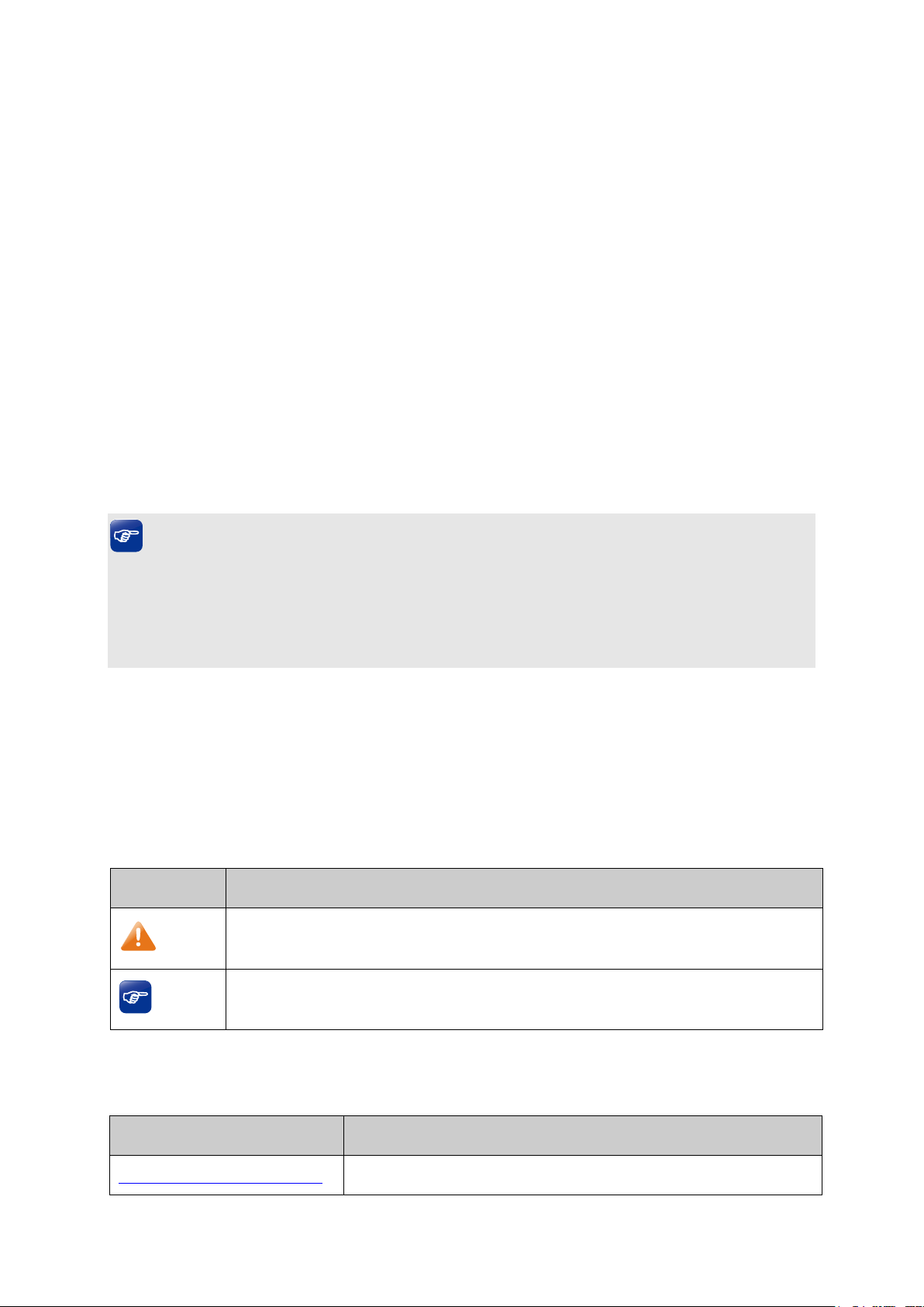
2.2.1 Front Panel
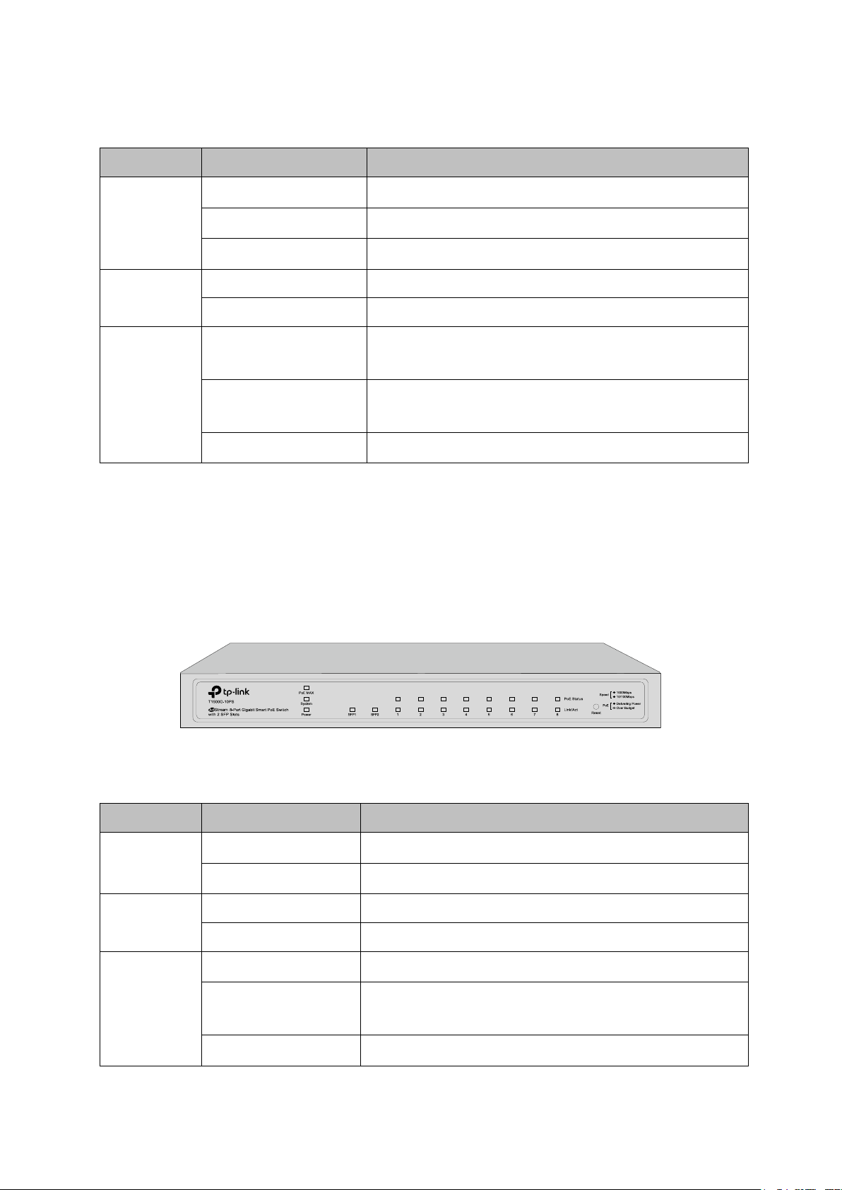
T1500G-10MPS
The front panel of T1500G-10MPS is shown as Figure 2-1.
Figure 2-1 Front Panel of
The following parts are located on the front panel of T1500G-10MPS:
LEDs
T1500G-10MPS has an LED mode switch button which is for switching the LED status
indication. When the Speed LED is on, the port LED is indicating the data transmission status.
When the PoE LED is on, the port LED is indicating the power supply status. By default, the
Speed LED is on. Pressing the mode switch button, the Speed LED will turn off and the PoE LED
T1500G-10MPS
will light up. Then the PoE LED will turn off after being on for 60 seconds and the Speed LED will
light up again.
When the Speed LED is on, the port LED is indicating the data transmission status.
PWR
7
Page 18
Name
Status
Indication
SYS
Flashing
The switch is working normally.
On/Off
The switch is working abnormally.
Green
All the fans work properly.
Yellow
Not all the fans work properly.
On
The remaining PoE power≤7W
on for 2 minutes.
Off
The remaining PoE power>7W
corresponding port, but no activity.
Flashing
Data is being transmitted or received.
corresponding port, but no activity.
Flashing
Data is being transmitted or received.
Off
No device is connected to the corresponding port.
corresponding port, but no activity.
Flashing
Data is being transmitted or received.
port, but no activity.
Flashing
Data is being transmitted or received.
Off
No device is connected to the corresponding port.
Name
Status
Indication
On
The switch is powered on.
Off
The switch is powered off or power supply is abnormal.
Flashing
Power supply is abnormal.
Flashing
The switch is working normally.
On/Off
The switch is working abnormally.
Green
All the fans work properly.
Yellow
Not all the fans work properly.
FAN
PoE MAX
Speed or
PoE
SPF1, SFP2
Green
Yellow
Green
Yellow
Flashing
On
On
On
On
The remaining PoE power keeps ≤7W after this LED is
A 1000Mbps device is connected to the
A 10/100Mbps device is connected to the
A 1000Mbps device is connected to the
A 100Mbps device is connected to the corresponding
When the PoE LED is on, the port LED is indicating the power supply status.
PWR
SYS
FAN
8
Page 19
Name
Status
Indication
On
The remaining PoE power≤7W
on for 2 minutes.
Off
The remaining PoE power>7W
On
The port is supplying power normally.
maximum power.
On
Overload or short circuit is detected.
Flashing
Power-on self-test has failed.
Off
No device is connected to the corresponding port.
corresponding port, but no activity.
Flashing
Data is being transmitted or received.
port, but no activity.
Flashing
Data is being transmitted or received.
Off
No device is connected to the corresponding port.
PoE MAX
Speed or
PoE
SPF1, SFP2
Green
Yellow
Green
Yellow
Flashing
Flashing
On
On
The remaining PoE power keeps ≤7W after this LED is
The supply power exceeds the corresponding port's
A 1000Mbps device is connected to the
A 100Mbps device is connected to the corresponding
Reset
Press this button for five seconds or above to reset the software setting back to factory default
setting.
10/100/1000Mbps RJ45 Port and PoE Port
Designed to connect to the device with a bandwidth of 10Mbps, 100Mbps or 1000Mbps. Each
has a corresponding Speed or PoE LED.
SFP Port
Designed to install the SFP module. T1500G-10MPS features 2 SFP transceiver ports.
T1500G-8T
The front panel of T1500G-8T is shown as Figure 2-2.
Figure 2-2 Front Panel of
T1500G-8T
9
Page 20
Name
Status
Indication
On
The switch is powered on.
Off
The switch is powered off or power supply is abnormal.
Flashing
Power supply is abnormal.
Flashing
The switch is working normally.
On/Off
The switch is working abnormally.
device.
10/100Mbps device.
Flashing
The corresponding port is transmitting/receiving data.
Name
Status
Indication
On(Green)
The switch is powered on.
Flashing/Off
The switch is powered off or power supply is abnormal.
Flashing
The switch is working normally.
On/Off
The switch is working abnormally.
On
The remaining PoE power≤7W
on for 2 minutes.
Off
The remaining PoE power>7W
The following parts are located on the front panel of T1500G-8T:
LEDs
Power
System
The corresponding port is connected to a 1000Mbps
The corresponding port is connected to a
1-8
On (Green)
On (Yellow)
Reset
Press this button for five seconds or above to reset the software setting back to factory default
settings.
T1500G-10PS
The front panel of T1500G-10PS is shown as Figure 2-3.
Figure 2-3 Front Panel of T1500G-10PS
The following parts are located on the front panel of T1500G-8T:
Power
System
PoE MAX
Flashing
The remaining PoE power keeps ≤7W after this LED is
10
Page 21
Name
Status
Indication
port, but no activity.
Flashing
Data is being transmitted or received.
corresponding port, but no activity.
Flashing
Data is being transmitted or received.
Off
No device is connected to the corresponding port.
port is connected to a Non-standard PD.
No PD is connected to the corresponding port, or no
port, but no activity.
Flashing
Data is being transmitted or received.
port, but no activity.
Flashing
Data is being transmitted or received.
Off
No device is connected to the corresponding port.
Link/Act
PoE Status
(Port 1-8)
Green
Yellow
On(Green)
Flashing
Green
Off
On
On
On
A 1000Mbps device is connected to the corresponding
A 10/100Mbps device is connected to the
The corresponding port is connected to a PoE PD and
supplying power.
The PoE power circuit is overloaded, in short, power
exceeded the user-defined value or the corresponding
power is supplied.
A 1000Mbps device is connected to the corresponding
SPF1, SFP2
On
Yellow
Reset
Press this button for five seconds or above to reset the software setting back to factory default
setting.
A 100Mbps device is connected to the corresponding
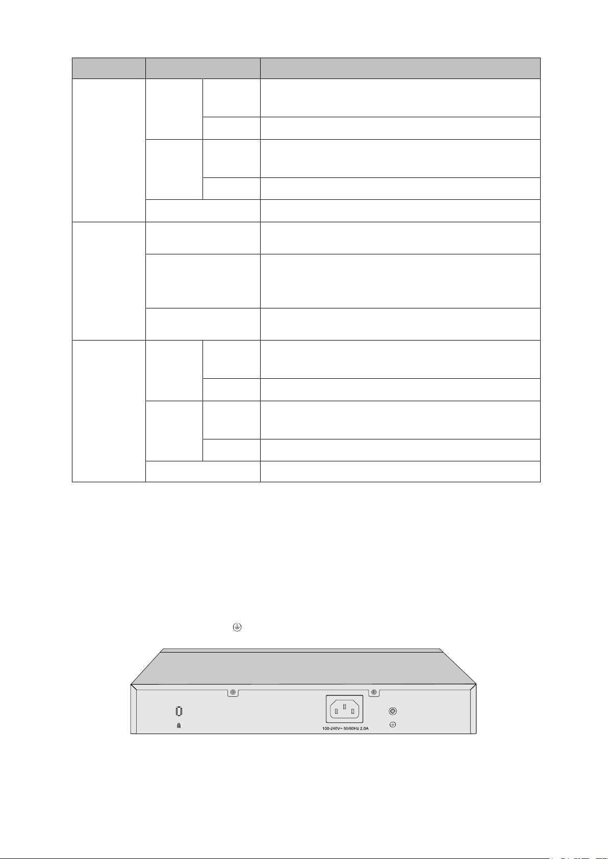
2.2.2 Rear Panel
T1500G-10MPS
The rear panel of T1500G-10MPS features a Kensington Security Slot, a power socket and a
Grounding Terminal (marked with
).
Figure 2-4 Rear Panel of the switch
11
Page 22
Kensington Security Slot
Secure the lock (not provided) into the security slot to prevent the device from being stolen.
Power Socket
Connect the female connector of the power cord here, and the male connector to the AC
(Alternating Current) power outlet. Please make sure the voltage of the power supply meets
the requirement of the input voltage.
Grounding Terminal
The switch already comes with lightning protection mechanism. You can also ground the
switch through the PE (Protecting Earth) cable of AC cord or with Ground Cable.
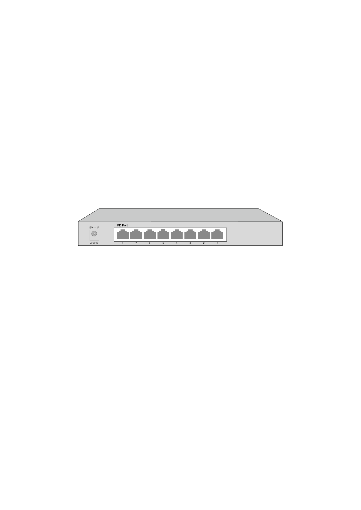
T1500G-8T
The rear panel of T1500G-8T features a power socket, 8 10/100/1000Mbps Ethernet ports and
a Kensington Security Slot.
Figure 2-5 Rear Panel of T1500G-8T
Power Socket
Connect the power socket and AC (Alternating Current) power outlet with the provided DC
power adapter and AC power cord. Please make sure the voltage of the power supply
meets the requirement of the input voltage.
Port 1-8
Designed to connect to the device with a bandwidth of 10Mbps, 100Mbps or 1000Mbps.
Each has a corresponding LED.
Please note that port 8 is a PD (Powered Device) port that supports being powered by a PSE
(Power Sourcing Equipment) complying with 802.3af standard. The DC power input takes
precedence over the PD port. If the DC input fails, the PoE input on the PD port will supply
power to the switch instead.
T1500G-10PS
The rear panel of T1500G-10PS features a power socket, 8 10/100/1000Mbps Ethernet ports
and 2 SFP transceiver ports.
12
Page 23

Figure 2-6 Rear Panel of T1500G-10PS
Power Socket
Connect the power socket and AC (Alternating Current) power outlet with the provided DC
power adapter and AC power cord. Please make sure the voltage of the power supply
meets the requirement of the input voltage.
10/100/1000Mbps RJ45 Port and PoE Port
Designed to connect to the device with a bandwidth of 10Mbps, 100Mbps or 1000Mbps.
Each has a corresponding Link/Act or PoE Status LED.
SFP Port
Designed to install the SFP module. T1500G-10PS features 2 SFP transceiver ports.
Return to CONTENTS
13
Page 24
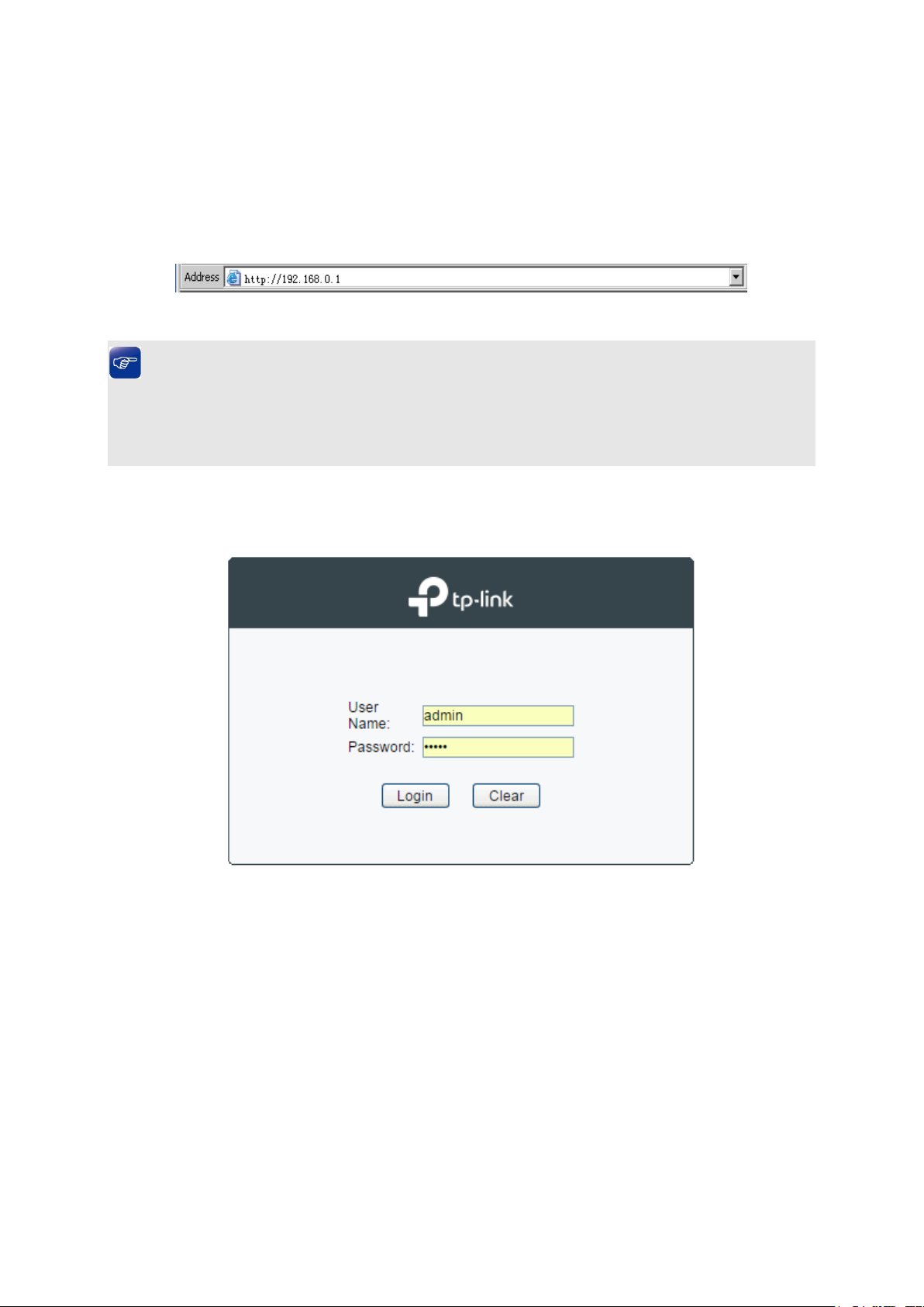
Chapter 3 Login to the Switch
3.1 Login
1) To access the configuration utility, open a web-browser and type in the default address
http://192.168.0.1 in the address field of the browser, then press the Enter key.
Figure 3-1 Web-browser
Tips:
To log in to the switch, the IP address of your PC should be set in the same subnet addresses
of the switch. The IP address is 192.168.0.x ("x" is any number from 2 to 254), Subnet Mask is
255.255.255.0. For the detailed instructions as to how to do this, please refer to Appendix B.
2) After a moment, a login window will appear, as shown in Figure 3-2. Enter admin for the User
Name and Password, both in lower case letters. Then click the Login button or press the
Enter key.
Figure 3-2 Login
3.2 Configuration
After a successful login, the main page will appear as Figure 3-3, and you can configure the
function by clicking the setup menu on the left side of the screen.
14
Page 25
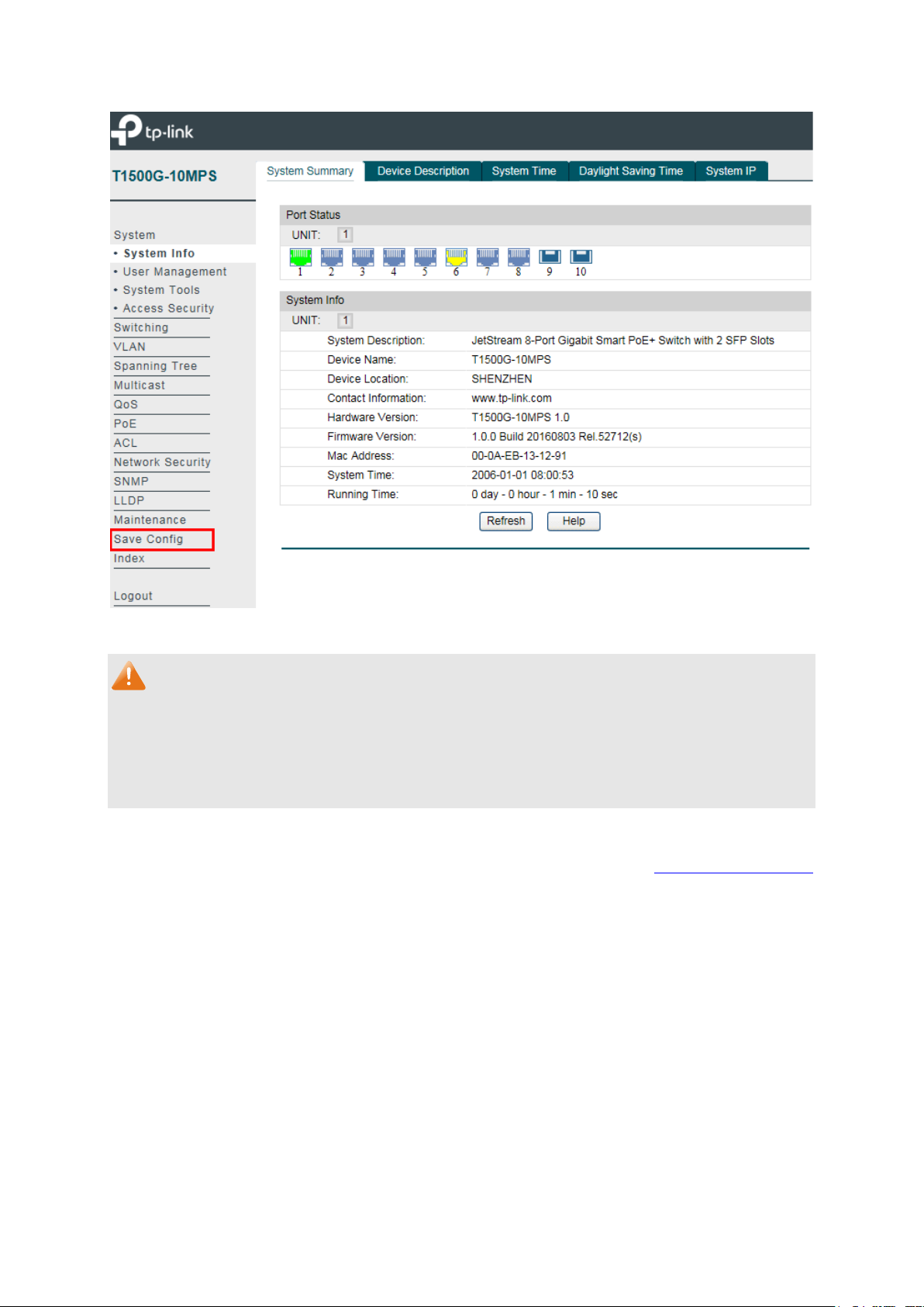
Figure 3-3 Main Setup-Menu
Note:
Clicking Apply can only make the new configurations effective before the switch is rebooted. If
you want to keep the configurations effective even the switch is rebooted, please click Save
Config. You are suggested to click Save Config before cutting off the power or rebooting the
switch to avoid losing the new configurations.
Return to CONTENTS
15
Page 26
Indicates the 1000Mbps port is not connected to a device.
Indicates the 1000Mbps port is at the speed of 1000Mbps.
Indicates the SFP port is not connected to a device.
Indicates the SFP port is at the speed of 1000Mbps.
Chapter 4 System
The System module is mainly for system configuration of the switch, including four submenus:
System Info, User Management, System Tools and Access Security.
4.1 System Info
The System Info, mainly for basic properties configuration, can be implemented on System
Summary, Device Description, System Time, Daylight Saving Time and System IP pages.
4.1.1 System Summary
On this page you can view the port connection status and the system information.
The port status diagram shows the working status of 8 10/100/1000Mbps RJ45 ports and 2
SFP ports of the switch.
Choose the menu System→System Info→System Summary to load the following page.
Figure 4-1 System Summary
Port Status
Indicates the 1000Mbps port is at the speed of 10Mbps or 100Mbps.
16
Page 27
Port:
Displays the port number of the switch.
Type:
Displays the type of the port.
Speed:
Displays the maximum transmission rate of the port.
Status:
Displays the connection status of the port.
Select Rx to display the bandwidth utilization of receiving
packets on this port.
on this port.
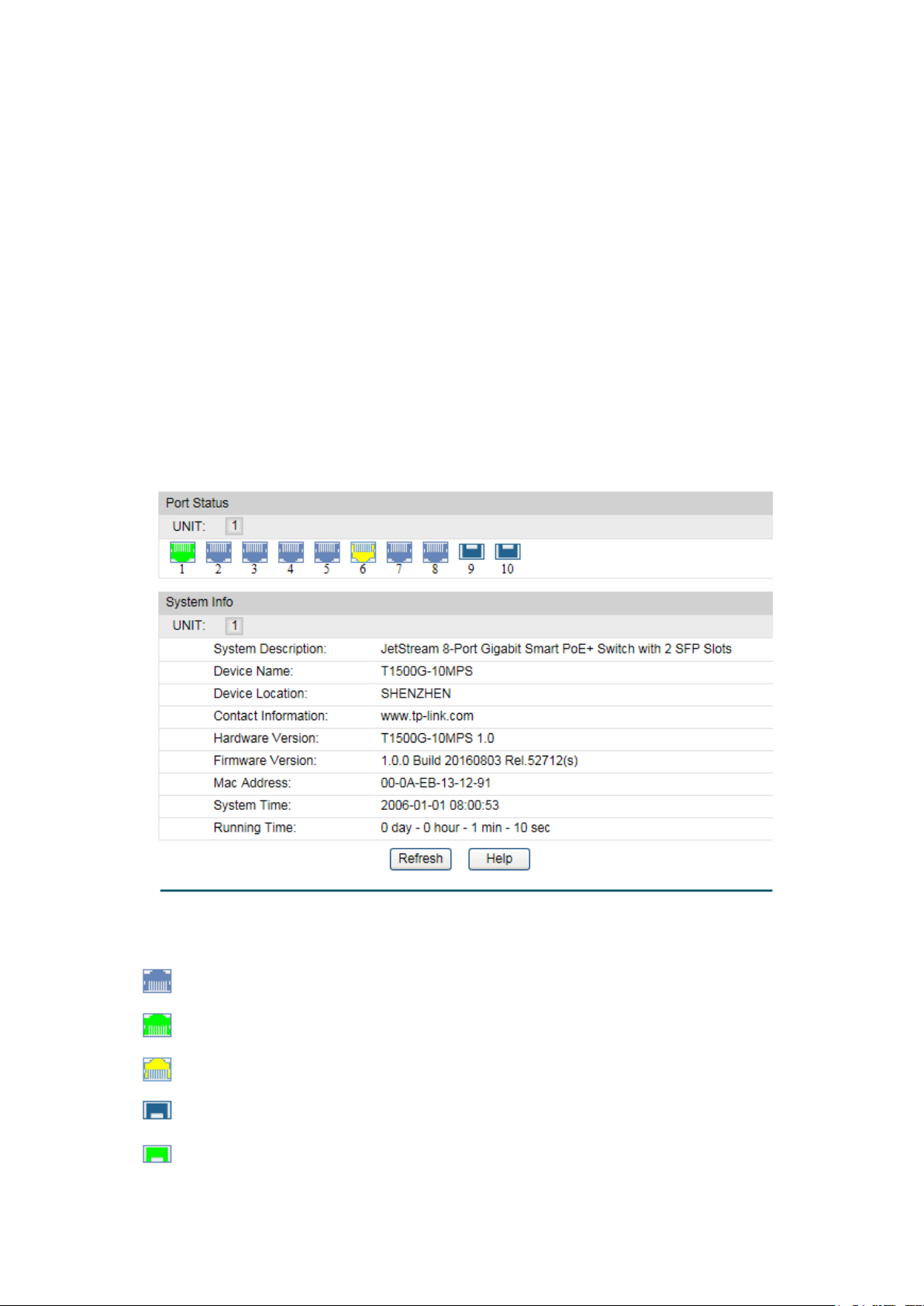
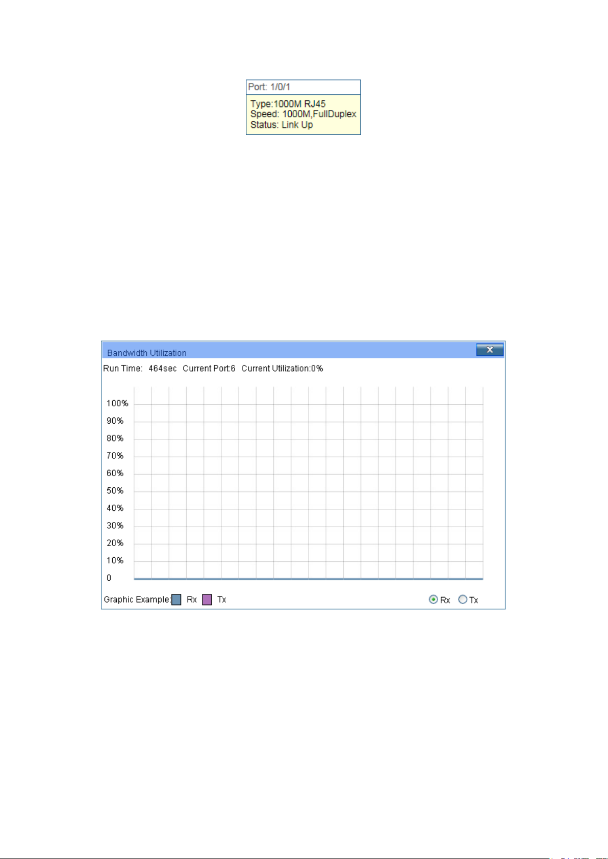
When the cursor moves on the port, the detailed information of the port will be displayed.
Figure 4-2 Port Information
Port Info
Click a port to display the bandwidth utilization on this port. The actual rate divided by
theoretical maximum rate is the bandwidth utilization. The following figure displays the
bandwidth utilization monitored every four seconds. Monitoring the bandwidth utilization on
each port facilitates you to monitor the network traffic and analyze the network abnormities.
Figure 4-3 Bandwidth Utilization
Bandwidth Utilization
Rx:
Tx: Select Tx to display the bandwidth utilization of sending packets
4.1.2 Device Description
On this page you can configure the description of the switch, including device name, device
location and system contact.
17
Page 28
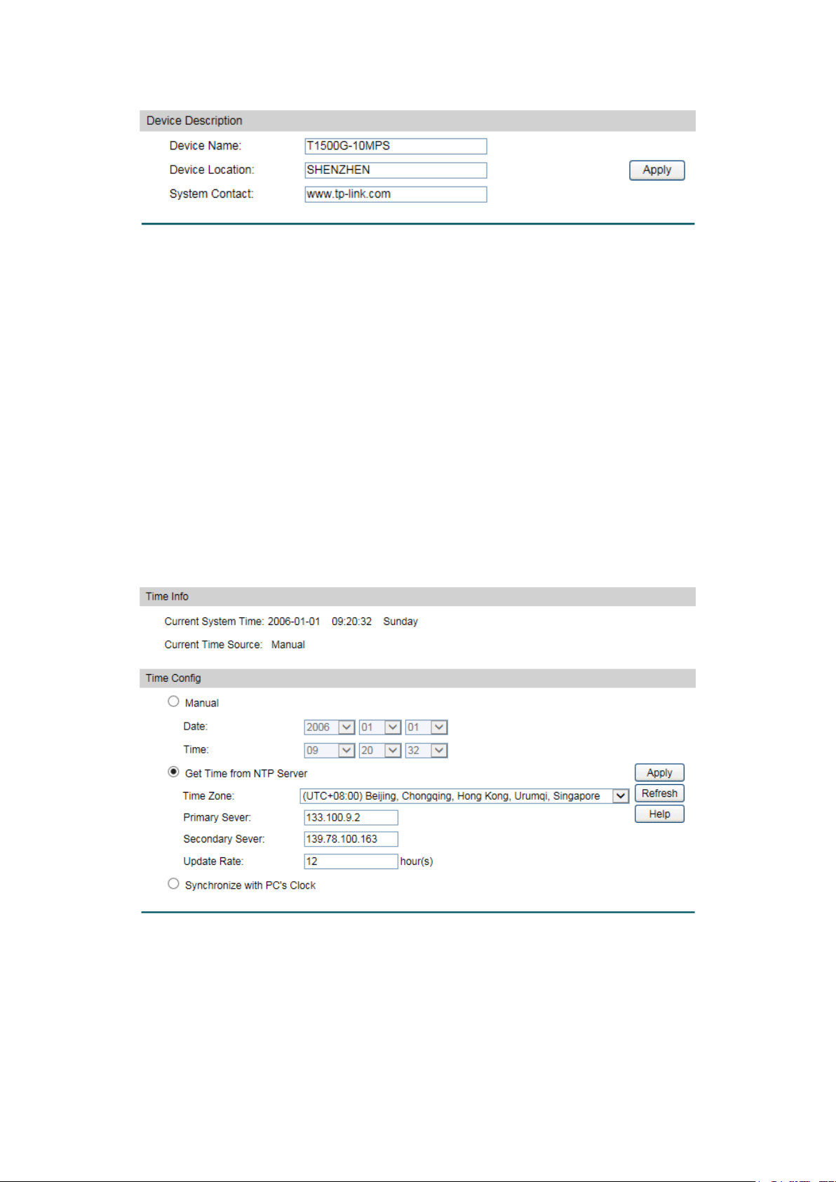
Device Name:
Enter the name of the switch.
Device Location:
Enter the location of the switch.
System Contact:
Enter your contact information.
Current System Date:
Displays the current date and time of the switch.
Current Time Source:
Displays the current time source of the switch.
Choose the menu System→System Info→Device Description to load the following page.
Figure 4-4 Device Description
The following entries are displayed on this screen:
Device Description
4.1.3 System Time
System Time is the time displayed while the switch is running. On this page you can configure the
system time and the settings here will be used for other time-based functions.
You can manually set the system time or synchronize with PC’s clock as the system time.
Choose the menu System→System Info→System Time to load the following page.
The following entries are displayed on this screen:
Time Info
Figure 4-5 System Time
18
Page 29
When this option is selected, you can set the date and time
manually.
Get Time from NTP
nfigure the time zone
Enter the IP Address for the
ify the rate fetching time from NTP
server.
Synchronize with
PC’S Clock:
clock is
utilized.
Time Config
Manual:
When this option is selected, you can co
Server:
and the IP Address for the NTP Server. The switch will get UTC
automatically if it has connected to an NTP Server.
Time Zone: Select your local time.
Primary/Secondary Server:
NTP Server.
Update Rate: Spec
When this option is selected, the administrator PC’s
Note:
1. The system time will be restored to the default when the switch is restarted and you need to
reconfigure the system time of the switch.
2. When Get Time from NTP Server is selected and no time server is configured, the switch will
get time from the time server of the Internet if it has connected to the Internet.
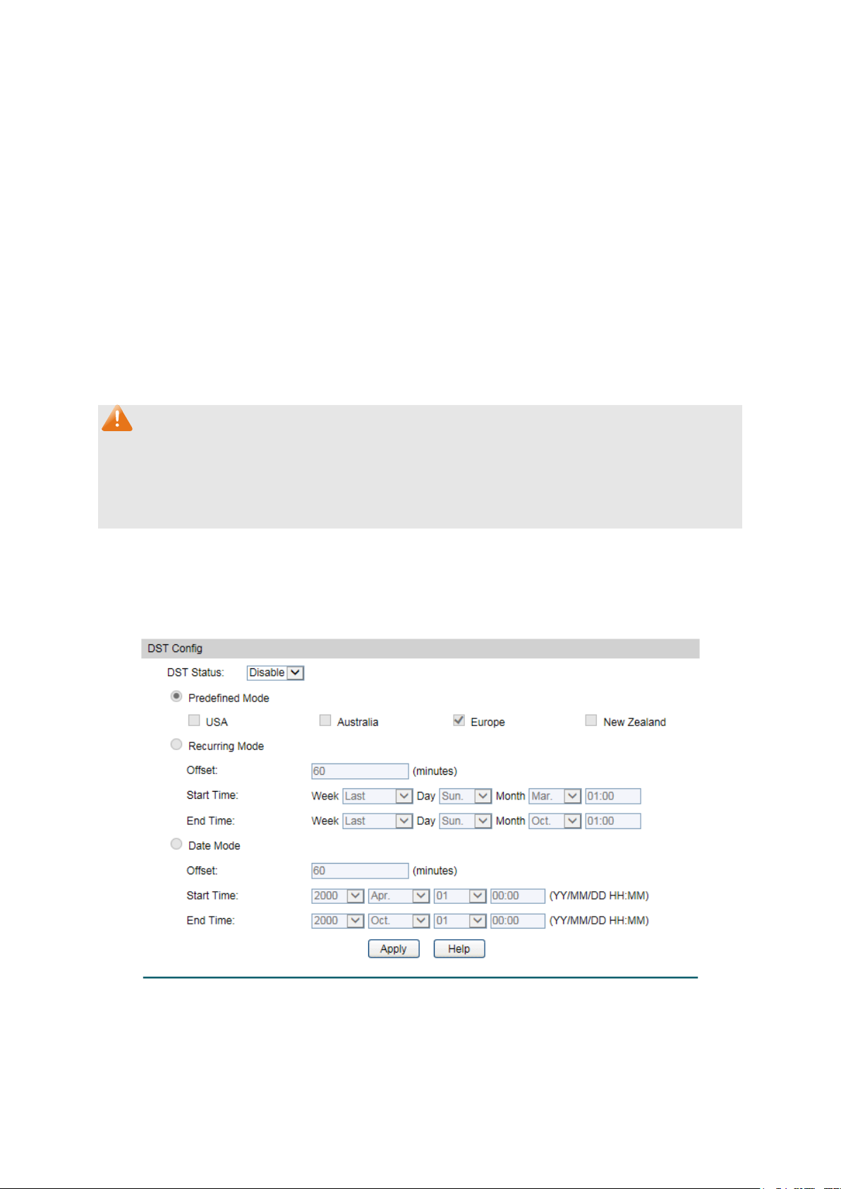
4.1.4 Daylight Saving Time
Here you can configure the Daylight Saving Time of the switch.
Choose the menu System→System Info→Daylight Saving Time to load the following page.
Figure 4-6 Daylight Saving Time
19
Page 30

DST Status:
Enable or disable the DST.
First Sunday in
First Sunday in
Last Sunday in
First
Sunday in April, 03:00.
Specify the DST configuration in recurring mode. This
cify the time adding in minutes when Daylight
Start/End Time: Select starting time and ending time of
Daylight Saving Time.
te mode. This configuration
he time adding in minutes when Daylight
Start/End Time: Select starting time and ending time of
Daylight Saving Time.
The following entries are displayed on this screen:
DST Config
Predefined Mode: Select a predefined DST configuration.
USA: Second Sunday in March, 02:00 to
November, 02:00.
Australia: First Sunday in October, 02:00 to
April, 03:00.
Europe: Last Sunday in March, 01:00 to
October, 01:00.
New Zealand: Last Sunday in September, 02:00 to
Recurring Mode:
configuration is recurring in use.
Offset: Spe
Saving Time comes.
Date Mode: Specify the DST configuration in Da
is recurring in use.
Offset: Specify t
Saving Time comes.
Note:
1. When the DST is disabled, the predefined mode, recurring mode and date mode cannot be
configured.
2. When the DST is enabled, the default daylight saving time is of European in predefined
mode.
4.1.5 System IP
Each device in the network possesses a unique IP Address. You can log on to the Web
management page to operate the switch using this IP Address. The switch supports three
modes to obtain an IP address: Static IP, DHCP and BOOTP. The IP address obtained using a
new mode will replace the original IP address. On this page you can configure the system IP of
the switch.
20
Page 31
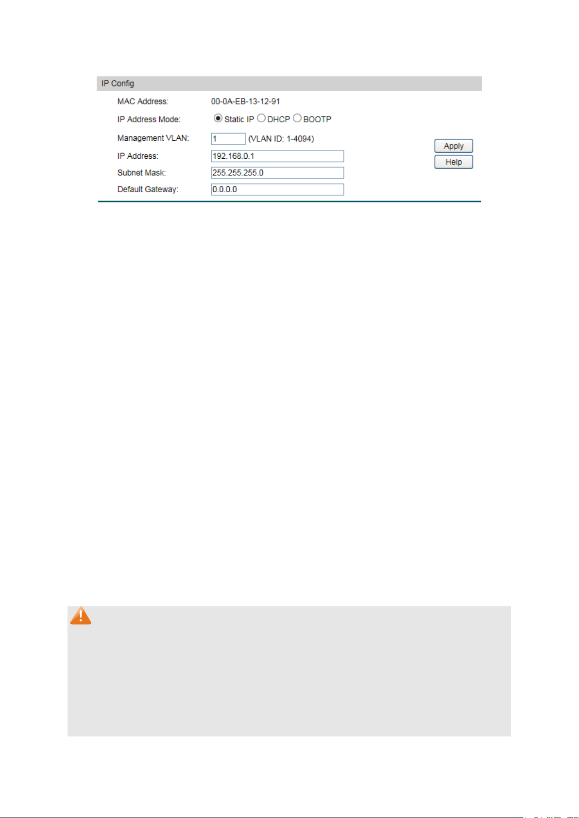
MAC Address:
Displays MAC Address of the switch.
Static IP: When this option is selected, you should enter IP
DHCP: When this option is selected, the switch will obtain
OOTP: When this option is selected, the switch will obtain
network parameters from the BOOTP Server.
Enter the ID of management VLAN, the only VLAN through which
you can get access to the switch. By default VLAN1 owning all
he Management VLAN and you can access the
switch via any port on the switch. However, if another VLAN is
created and set to be the Management VLAN, you may have to
reconnect the management station to a port that is a member of
the Management VLAN.
Enter the system IP of the switch. The default system IP is
192.168.0.1 and you can change it appropriate to your needs.
Subnet Mask:
Enter the subnet mask of the switch.
Default Gateway:
Enter the default gateway of the switch.
Choose the menu System→System Info→System IP to load the following page.
Figure 4-7 System IP
The following entries are displayed on this screen:
IP Config
IP Address Mode: Select the mode to obtain IP Address for the switch.
Address, Subnet Mask and Default Gateway manually.
network parameters from the DHCP Server.
B
Management VLAN:
the ports is t
IP Address:
Note:
1. Changing the IP address to a different IP segment will interrupt the network communication,
so please keep the new IP address in the same IP segment with the local network.
2. The switch only possesses one IP address. The IP address configured will replace the
original IP address.
3. If the switch gets the IP address from DHCP server, you can see the configuration of the
switch in the DHCP server; if DHCP option is selected but no DHCP server exists in the
network, a few minutes later, the switch will restore the setting to the default.
21
Page 32

4. If DHCP or BOOTP option is selected, the switch will get network parameters dynamically
from the Internet, which means that IP address, subnet mask and default gateway cannot
be configured.
5. By default, the IP address is 192.168.0.1.
4.2 User Management
User Management functions to configure the user name and password for users to log on to
the Web management page with a certain access level so as to protect the settings of the
switch from being randomly changed.
The User Management function can be implemented on User Table and User Config pages.
4.2.1 User Table
On this page you can view the information about the current users of the switch.
Choose the menu System→User Management→User Table to load the following page.
Figure 4-8 User Table
4.2.2 User Config
On this page you can configure the access level of the user to log on to the Web management
page. The switch provides four access levels: Admin, Operator, Power User and User. “Admin”
means that you can edit, modify and view all the settings of different functions. “Operator”
means that you can edit, modify and view most of the settings of different functions. “Power
User” means that you can edit, modify and view some of the settings of different functions.
“User” means that you can only view some of the settings of different functions without the
right to edit or modify. The Web management pages contained in this guide are subject to the admin’s
login without any explanation.
22
Page 33

User Name:
Create a name for users’ login.
Admin: Admin can edit, modify and view all the settings of
Operator: Operator can edit, modify and view most of the
Power User: Power User can edit, modify and view some of
User: User only can view the settings without the right to edit
and modify.
Password:
Type a password for users’ login.
Confirm Password:
Retype the password.
esponding user
The current user information
can’t be deleted.
User ID, Name and
Access Level:
edit the
corresponding user information. After modifying the settings,
button to make the modification
effective. Access level and user status of the current user
information cannot be modified.
Choose the menu System→User Management→User Config to load the following page.
Figure 4-9 User Config
The following entries are displayed on this screen:
User Info
Access Level: Select the access level to login.
different functions.
settings in different functions.
the settings in different functions.
User Table
Select: Select the desired entry to delete the corr
information. It is multi-optional.
Displays the current user ID, user name and access level.
Operation:
Click the Edit button of the desired entry, and you can
please click the Modify
23
Page 34

Select:
Select the unit(s).
Unit:
Displays the unit ID.
Image:
Next Startup Image:
Select the next startup image.
Backup Image:
Select the backup boot image.
4.3 System Tools
The System Tools function, allowing you to manage the configuration file of the switch, can be
implemented on Boot Config, Config Restore, Config Backup, Firmware Upgrade, System
Reboot and System Reset pages.
4.3.1 Boot Config
On this page you can configure the boot file of the switch. When the switch is powered on, it will
start up with the startup image. If it fails, it will try to start up with the backup image. If this fails
too, you will enter into the bootutil menu of the switch.
Choose the menu System → System Tools → Boot Config to load the following page.
Figure 4-10 Boot Config
The following entries are displayed on this screen:
Boot Table
Current Startup
Displays the current startup image.
4.3.2 Config Restore
On this page you can upload a backup configuration file to restore your switch to this previous
configuration.
24
Page 35

ile and click the
Import button to restore the startup configuration file.
button to save the current configuration as a
file to your computer. You are suggested to take this measure
before upgrading.
Choose the menu System→System Tools→Config Restore to load the following page.
Figure 4-11 Config Restore
The following entries are displayed on this screen:
Config Restore
Restore Config: Click the Browse button to select a backup f
Note:
1. It will take a few minutes to restore the configuration. Please wait without any operation.
2. To avoid any damage, please don’t power down the switch while being restored.
3. After being restored, the current settings of the switch will be lost. Wrong uploaded
configuration file may cause the switch unmanaged.
4.3.3 Config Backup
On this page you can download the current configuration and save it as a file to your computer
for your future configuration restore.
Choose the menu System→System Tools→Config Backup to load the following page.
Figure 4-12 Config Backup
The following entries are displayed on this screen:
Config Backup
Backup Config: Click the Export
25
Page 36

Note:
It will take a few minutes to backup the configuration. Please wait without any operation.
4.3.4 Firmware Upgrade
The switch system can be upgraded via the Web management page. To upgrade the system is
to get more functions and better performance. Go to http://www.tp-link.com
updated firmware.
Choose the menu System→System Tools→Firmware Upgrade to load the following page.
to download the
Figure 4-13 Firmware Upgrade
Please pay attention to the checkbox “After upgrading, the device will reboot automatically
with the backup image”. If the checkbox is checked, the switch will reboot with the uploaded
firmware file, and the current Next Startup Image will switch to the Backup Image. If the
checkbox is not checked, the uploaded firmware file will take place of the Backup Image. To
start with the uploaded firmware, you should exchange the Next Startup Image and Backup
Image in Boot Config
Note:
1. Don’t interrupt the upgrade.
2. Please select the proper software version matching with your hardware to upgrade.
3. To avoid damage, please don't turn off the device while upgrading.
4. After upgrading, the device will reboot automatically.
5. You are suggested to backup the configuration before upgrading.
and reboot the switch.
4.3.5 System Reboot
On this page you can reboot the switch and return to the login page. Please save the current
configuration before rebooting to avoid losing the configuration unsaved
26
Page 37

Choose the menu System→System Tools→System Reboot to load the following page.
Figure 4-14 System Reboot
Note:
To avoid damage, please don't turn off the device while rebooting.
4.3.6 System Reset
On this page you can reset the switch to the default. All the settings will be cleared after the
switch is reset.
Choose the menu System→System Tools→System Reset to load the following page.
Figure 4-15 System Reset
Note:
After the system is reset, the switch will be reset to the default and all the settings will be
cleared.
4.4 Access Security
Access Security provides different security measures for the remote login so as to enhance
the configuration management security. It can be implemented on Access Control, HTTP
Config, HTTPS Config, SSH Config and Telnet Config pages.
4.4.1 Access Control
On this page you can control the users logging on to the Web management page to enhance
the configuration management security.
27
Page 38

log on to the Web
range of the users
based: Select this option to limit the MAC Address of
Port-based: Select this option to limit the ports for login.
Access Interface:
Select the interface for access control to apply.
based mode
re are
allowed for login.
based mode is
selected. Only the user with this MAC Address you set here are
allowed for login.
Choose the menu System→Access Security→Access Control to load the following page.
Figure 4-16 Access Control
The following entries are displayed on this screen:
Access Control Config
Control Mode: Select the control mode for users to
management page.
Disable: Select to disable Access Control function.
IP-based: Select this option to limit the IP-
for login.
MAC-
the users for login.
IP Address & Mask These fields is available to configure only when IP-
is selected. Only the users within the IP-range you set he
MAC Address: The field is available to configure only when MAC-
4.4.2 HTTP Config
With the help of HTTP (Hyper Text Transfer Protocol), you can manage the switch through a
standard browser. The standards development of HTTP was coordinated by the Internet
Engineering Task Force and the World Wide Web Consortium.
On this page you can configure the HTTP function.
28
Page 39

HTTP:
Select Enable/Disable the HTTP function on the switch.
If you do nothing with the Web management page within the
reconfigure, please login again.
Number Control:
Select Enable/Disable the Number Control function.
Enter the maximum number of the users logging on to the Web
management page as Admin.
Enter the maximum number of the users logging on to the Web
management page as Operator.
the maximum number of the users logging on to the Web
management page as Power User.
Enter the maximum number of the users logging on to the Web
management page as User.
Choose the menu System→Access Security→HTTP Config to load the following page.
Figure 4-17 HTTP Config
The following entries are displayed on this screen
Global Config
Session Config
Session Timeout:
timeout time, the system will log out automatically. If you want to
Access User Number
Admin Number:
Operator Number:
Power User
Enter
Number:
:
User Number:
4.4.3 HTTPS Config
SSL (Secure Sockets Layer), a security protocol, is to provide a secure connection for the
application layer protocol (e.g. HTTP) communication based on TCP. SSL is widely used to
29
Page 40

secure the data transmission between the Web browser and servers. It is mainly applied
through ecommerce and online banking.
SSL mainly provides the following services:
1. Authenticate the users and the servers based on the certificates to ensure the data are
transmitted to the correct users and servers;
2. Encrypt the data transmission to prevent the data being intercepted;
3. Maintain the integrality of the data to prevent the data being altered in the transmission.
Adopting asymmetrical encryption technology, SSL uses key pair to encrypt/decrypt
information. A key pair refers to a public key (contained in the certificate) and its corresponding
private key. By default the switch has a certificate (self-signed certificate) and a corresponding
private key. The Certificate/Key Download function enables the user to replace the default key
pair.
After SSL is effective, you can log on to the Web management page via https://192.168.0.1
. For
the first time you use HTTPS connection to log into the switch with the default certificate, you
will be prompted that “The security certificate presented by this website was not issued by a
trusted certificate authority” or “Certificate Errors”. Please add this certificate to trusted
certificates or continue to this website.
On this page you can configure the HTTPS function.
Choose the menu System→Access Security→HTTPS to load the following page.
30
Page 41

HTTPS:
Select Enable/Disable the HTTPS function on the switch.
e Sockets Layer Version 3.0. By default,
it’s enabled.
Enable or Disable Transport Layer Security Version 1.0. By
default, it’s enabled.
bit encryption and
MD5 for message digest. By default, it’s enabled.
Figure 4-18 HTTPS Config
The following entries are displayed on this screen
Global Config
SSL Version 3: Enable or Disable Secur
TLS Version 1:
CipherSuite Config
RSA_WITH_RC4_128_MD5: Key exchange with RC4 128-
:
31
Page 42

bit encryption and
SHA for message digest. By default, it’s enabled.
CBC for message
encryption and SHA for message digest. By
default, it’s enabled.
CBC
for message encryption and SHA for message
digest. By default, it’s enabled.
the
reconfigure, please login again.
Number Control:
Select Enable/Disable the Number Control function.
to the Web
management page as Admin.
Enter the maximum number of the users logging on to the Web
management page as Operator.
Enter the maximum number of the users logging on to the Web
management page as Power User.
Enter the maximum number of the users logging on to the Web
management page as User.
Select the desired certificate to download to the switch. The
certificate must be BASE64 encoded.
Select the desired key to download to the switch. The key must
be BASE64 encoded.
RSA_WITH_RC4_128_SHA: Key exchange with RC4 128-
RSA_WITH_DES_CBC_SHA: Key exchange with DES-
RSA_WITH_3DES_EDE_CBC_SHA: Key exchange with 3DES and DES-EDE3-
Session Config
Session Timeout: If you do nothing with the Web management page within
timeout time, the system will log out automatically. If you want to
Access User Number
Admin Number: Enter the maximum number of the users logging on
Operator Number:
Power User
Number:
User Number:
Certificate Download
Certificate File:
Key Download
Key File:
Note:
1. The SSL certificate and key downloaded must match each other; otherwise the HTTPS
connection will not work.
2. To establish a secured connection using https, please enter https:// into the URL field of
the browser.
3. It may take more time for https connection than that for http connection, because https
connection involves authentication, encryption and decryption etc.
32
Page 43
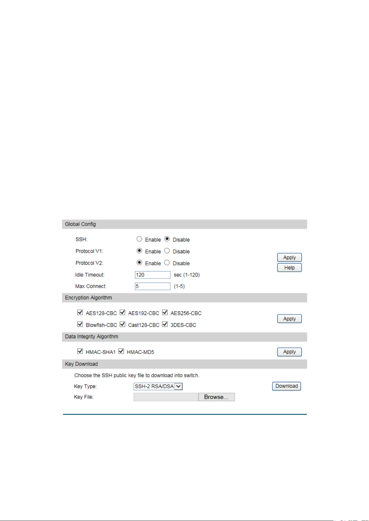
SSH:
Select Enable/Disable SSH function.
4.4.4 SSH Config
As stipulated by IETF (Internet Engineering Task Force), SSH (Secure Shell) is a security
protocol established on application and transport layers. SSH-encrypted-connection is similar
to a telnet connection, but essentially the old telnet remote management method is not safe,
because the password and data transmitted with plain-text can be easily intercepted. SSH can
provide information security and powerful authentication when you log on to the switch
remotely through an insecure network environment. It can encrypt all the transmission data and
prevent the information in a remote management being leaked.
Comprising server and client, SSH has two versions, V1 and V2 which are not compatible with
each other. In the communication, SSH server and client can auto-negotiate the SSH version
and the encryption algorithm. After getting a successful negotiation, the client sends
authentication request to the server for login, and then the two can communicate with each
other after successful authentication. This switch supports SSH server and you can log on to
the switch via SSH connection using SSH client software.
SSH key can be downloaded into the switch. If the key is successfully downloaded, the
certificate authentication will be preferred for SSH access to the switch.
Choose the menu System→Access Security→SSH Config to load the following page.
The following entries are displayed on this screen
Global Config
Figure 4-19 SSH Config
:
33
Page 44

Protocol V1:
Select Enable/Disable SSH V1 to be the supported protocol.
Protocol V2:
Select Enable/Disable SSH V2 to be the supported protocol.
Idle Timeout:
Specify the idle timeout time. The system will automatically
release the connection when the time is up. The default time is
120 seconds.
Specify the maximum number of the connections to the SSH
server. No new connection will be established when the number
of the connections reaches the maximum number you set. The
default value is 5.
CBC algorithm of
SSH.
CBC algorithm of
SSH.
CBC algorithm of
SSH.
CBC algorithm of
SSH.
CBC algorithm of
SSH.
CBC algorithm of
SSH.
3DES-CBC:
Select the checkbox to enable the 3DES-CBC algorithm of SSH.
SHA1 algorithm of
SSH.
MD5 algorithm of
SSH.
Select the type of SSH Key to download. The switch supports
two types: SSH-2 RSA/DSA and SSH-1 RSA.
Please ensure the key length of the downloaded file is in the
range of 512 to 3072 bits.
Max Connect:
Encryption Algorithm
Configure SSH encryption algorithms.
AES128-CBC:
Select the checkbox to enable the AES128-
AES128-CBC: Select the checkbox to enable the AES128-
AES192-CBC: Select the checkbox to enable the AES192-
AES256-CBC: Select the checkbox to enable the AES256-
Blowfish-CBC: Select the checkbox to enable the Blowfish-
Cast128-CBC: Select the checkbox to enable the Cast128-
Data Integrity Algorithm
Configure SSH data integrity algorithms.
HMAC-SHA1:
Select the checkbox to enable the HMAC-
HMAC-MD5: Select the checkbox to enable the HMAC-
Key Download
Key Type:
Key File:
34
Page 45

button to download the desired key file to
the switch.
Download: Click the Download
Note:
1. It will take a long time to download the key file. Please wait without any operation.
2. After the Key File is downloaded, the user's original key of the same type will be replaced.
The wrong downloaded file will result in the SSH access to the switch via Password
authentication.
Application Example 1 for SSH:
Network Requirements
1. Log on to the switch via password authentication using SSH and the SSH function is
enabled on the switch.
2. PuTTY client software is recommended.
Configuration Procedure
1. Open the software to log on to the interface of PuTTY. Enter the IP address of the switch
into Host Name field; keep the default value 22 in the Port field; select SSH as the
Connection type.
2. Click the Open button in the above figure to log on to the switch. Enter the login user name
and password, and then you can continue to configure the switch.
35
Page 46

Application Example 2 for SSH:
Network Requirements
1. Log on to the switch via key authentication using SSH and the SSH function is enabled on
the switch.
2. PuTTY client software is recommended.
Configuration Procedure
1. Select the key type and key length, and generate SSH key.
Note:
1. The key length is in the range of 512 to 3072 bits.
2. During the key generation, randomly moving the mouse quickly can accelerate the key
generation.
36
Page 47

2. After the key is successfully generated, please save the public key and private key to the
computer.
3. On the Web management page of the switch, download the public key file saved in the
computer to the switch.
Note:
1. The key type should accord with the type of the key file.
2. The SSH key downloading cannot be interrupted.
4. After the public key and private key are downloaded, please log on to the interface of PuTTY
and enter the IP address for login.
37
Page 48

5. Click Browse to download the private key file to SSH client software and click Open.
After successful authentication, please enter the login user name. If you log on to the switch
without entering password, it indicates that the key has been successfully downloaded.
38
Page 49

Telnet:
Select Enable/Disable Telnet function globally on the switch.
4.4.5 Telnet Config
On this page you can Enable/Disable Telnet function globally on the switch.
Choose the menu System→Access Security→Telnet Config to load the following page.
Figure 4-20 Telnet Config
The following entries are displayed on this screen:
Global Config
Return to CONTENTS
39
Page 50

Jumbo: Specify the global jumbo size. The default maximum
transmission unit (MTU) size is 1518 bytes.
UNIT:1/LAGS:
to
configure the link aggregation groups.
Select:
Select the desired port for configuration. It is multi-optional.
Chapter 5 Switching
Switching module is used to configure the basic functions of the switch, including five
submenus: Port, LAG, Traffic Monitor, MAC Address and DHCP Filtering.
5.1 Port
The Port function, allowing you to configure the basic features for the port, is implemented on
the Port Config, Port Mirror, Port Security , Port Isolation and Loopback Detection pages.
5.1.1 Port Config
On this page, you can configure the basic parameters for the ports. When the port is disabled, the
packets on the port will be discarded. Disabling the port which is vacant for a long time can
reduce the power consumption effectively. And you can enable the port when it is in need.
The parameters will affect the working mode of the port, please set the parameters appropriate
to your needs.
Choose the menu Switching→Port→Port Config to load the following page.
Figure 5-1 Port Config
The following entries are displayed on this screen:
Global Config
Port Config
Click 1 to configure the physical ports. Click LAGS
40
Page 51

Port:
Displays the port number.
Type:
Displays the medium type of the port.
Description:
Give a description to the port for identification.
Status: Allows you to Enable/Disable the port. When Enable is
selected, the port can forward the packets normally.
Speed:
or the port. The device connected to
the switch should be in the same Speed and Duplex mode with
the switch. When 'Auto' is selected, the Speed mode will be
determined by auto negotiation.
Duplex:
ed,
the Duplex mode will be determined by auto negotiation.
Flow Control:
Allows you to Enable/Disable the Flow Control feature. When
Flow Control is enabled, the switch can synchronize the speed
with its peer to avoid the packet loss caused by congestion.
LAG:
Displays the LAG number which the port belongs to.
Select the Duplex mode for the port. When ‘Auto’ is select
Note:
1. The switch cannot be managed through the disabled port. Please enable the port which is
used to manage the switch.
2. The parameters of the port members in a LAG should be set as the same.
3. When using the SFP port with a 100M module or a gigabit module, you need to configure
its corresponding Speed and Duplex mode. For 100M module, please select 100MFD
while select 1000MFD for gigabit module. By default, the Speed and Duplex mode of SFP
port is 1000MFD.
Select the Speed mode f
5.1.2 Port Mirror
Port Mirror, the packets obtaining technology, functions to forward copies of packets from
one/multiple ports (mirrored port) to a specific port (mirroring port). Usually, the mirroring port
is connected to a data diagnose device, which is used to analyze the mirrored packets for
monitoring and troubleshooting the network.
Choose the menu Switching→Port→Port Mirror to load the following page.
Figure 5-2 Mirror Group List
41
Page 52

Session:
Displays the mirror session number.
Destination:
Displays the mirroring port.
The value will be "Ingress Only",
"Egress Only" or “Both”.
Source:
Displays the mirrored ports.
, or clear
the mirror session configuration by clicking the Clear.
Input or select a physical port from the port panel as the
mirroring port.
Mirror Session List
Mode: Displays the mirror mode.
Operation: You can configure the mirror session by clicking Edit
Click Edit to display the following figure.
Figure 5-3 Port Mirror Config
The following entries are displayed on this screen:
Destination Port
Destination Port:
42
Page 53

Select:
Select the desired port as a mirrored port. It is multi-optional.
Port:
Displays the port number.
Select Enable/Disable the Ingress feature. When the Ingress is
be copied to the mirroring port.
Enable/Disable the Egress feature. When the Egress is
copied to the mirroring port.
Displays the LAG number which the port belongs to. The LAG
port or mirroring
port.
Source Port
Ingress:
enabled, the incoming packets received by the mirrored port will
Egress: Select
enabled, the outgoing packets sent by the mirrored port will be
LAG:
member cannot be selected as the mirrored
Note:
1. The LAG member cannot be selected as the mirrored port or mirroring port.
2. A port cannot be set as the mirrored port and the mirroring port simultaneously.
3. The Port Mirror function can span the multiple VLANs.
5.1.3 Port Security
MAC Address Table maintains the mapping relationship between the port and the MAC
address of the connected device, which is the base of the packet forwarding. The capacity of
MAC Address Table is fixed. MAC Address Attack is the attack method that the attacker takes
to obtain the network information illegally. The attacker uses tools to generate the cheating
MAC address and quickly occupy the MAC Address Table. When the MAC Address Table is full,
the switch will broadcast the packets to all the ports. At this moment, the attacker can obtain
the network information via various sniffers and attacks. When the MAC Address Table is full,
the packets traffic will flood to all the ports, which results in overload, lower speed, packets
drop and even breakdown of the system.
Port Security is to protect the switch from the malicious MAC Address Attack by limiting the
maximum number of MAC addresses that can be learned on the port. The port with Port
Security feature enabled will learn the MAC address dynamically. When the learned MAC
address number reaches the maximum, the port will stop learning. Thereafter, the other
devices with the MAC address unlearned cannot access to the network via this port.
43
Page 54

Select
multi-optional.
Port:
Displays the port number.
Max Learned MAC
learned on the port.
Learned Num
learned on the port.
Learn Mode
entries will be saved even the switch is rebooted.
Status
Packets arrived on the port with new MAC
addresses will be dropped when the threshold limit is
Choose the menu Switching→Port→Port Security to load the following page.
Figure 5-4 Port Security
The following entries are displayed on this screen:
Port Security
: Select the desired port for Port Security configuration. It is
: Specify the maximum number of MAC addresses that can be
: Displays the number of MAC addresses that have been
: Select the Learn Mode for the port.
• Dynamic: When Dynamic mode is selected, the learned
MAC address will be deleted automatically after the aging
time.
• Static: When Static mode is selected, the learned MAC
address will be out of the influence of the aging time and
can only be deleted manually. The learned entries will be
cleared after the switch is rebooted.
• Permanent: When Permanent mode is selected, the
learned MAC address will be out of the influence of the
aging time and can only be deleted manually. The learned
: Choose the mode that the switch adopts when the threshold
limit on selected port is exceeded.
• Drop:
44
Page 55
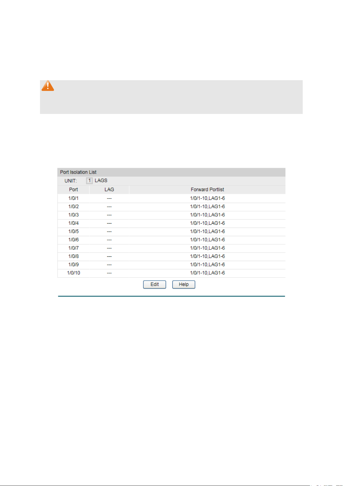
exceeded.
Disable: The threshold is not valid.
Click 1 to show the information of the physical ports. Click
LAGS to show the information of the link aggregation groups.
Port:
Displays the port number.
LAG :
Displays the LAG number which the port belongs to.
Forward Portlist:
Displays the forward portlist.
• Forward: Packets arrived on the port with new MAC
addresses will be forwarded but the addresses will not be
learned when the threshold limit is exceeded.
•
Note:
The Port Security function is disabled for the LAG port member. Only the port is removed from
the LAG, will the Port Security function be available for the port.
5.1.4 Port Isolation
Port Isolation provides a method of restricting traffic flow to improve the network security by
forbidding the port to forward packets to the ports that are not on its forward portlist.
Choose the menu Switching→Port→Port Isolation to load the following page.
The following entries are displayed on this screen:
Figure 5-5 Port Isolation
Port Isolation List
UNIT :1/LAGS :
45
Page 56

Click Edit to display the following figure.
Figure 5-6 Port Isolation Config
5.1.5 Loopback Detection
With loopback detection feature enabled, the switch can detect loops using loopback
detection packets. When a loop is detected, the switch will display an alert or further block the
corresponding port according to the port configuration.
Choose the menu Switching→Port→Loopback Detection to load the following page.
Figure 5-7 Loopback Detection Config
46
Page 57

Status:
Here you can enable or disable Loopback Detection function
globally.
Set a Loopback Detection interval between 1 and 1000
seconds. By default, it’s 30 seconds.
Time after which the blocked port would automatically recover
. It can be set as integral times of detection
interval.
Web Refresh Status:
Here you can enable or disable web automatic refresh.
h interval between 3 and 100 seconds. By
default, it’s 6 seconds.
to configure
the link aggregation groups.
It
is multi-optional.
Port:
Displays the port number.
Status:
Enable or disable Loopback Detection function for the port.
block the port.
Manual: Block status only can be removed manually.
Loop Status:
Displays the port status whether a loopback is detected.
Block Status:
Displays the port status about block or unblock.
LAG:
Displays the LAG number the port belongs to.
he loop or block
status of selected ports.
The following entries are displayed on this screen:
Global Config
LoopbackDetection
Detection Interval:
Automatic
Recovery Time:
to normal status
Web Refresh Interval: Set a web refres
Port Config
UNIT:1/LAGS: Click 1 to configure the physical ports. Click LAGS
Select: Select the desired port for Loopback Detection configuration.
Operation Mode: Select the mode how the switch processes the detected loops.
• Alert: When a loop is detected, display an alert.
• Port based: When a loop is detected, display an alert and
Recovery Mode: Select the mode how the blocked port recovers to normal status.
• Auto: Block status can be automatically removed after
recovery time.
•
Recover: Click the Recover button to manually remove t
Note:
Loopback Detection must coordinate with storm control.
47
Page 58

Hash Algorithm:
Select the applied scope of Aggregate Arithmetic, which
5.2 LAG
LAG (Link Aggregation Group) is to combine a number of ports together to make a single
high-bandwidth data path, so as to implement the traffic load sharing among the member ports
in the group and to enhance the connection reliability.
For the member ports in an aggregation group, their basic configuration must be the same. The
basic configuration includes STP, QoS, VLAN, port attributes, MAC Address Learning mode
and other associated settings. The further explains are following:
If the ports, which are enabled for the 802.1Q VLAN, STP, QoS and Port Configuration
(Speed and Flow Control), are in a LAG, their configurations should be the same.
The ports, which are enabled for the half-duplex, Port Security, Port Mirror and MAC
Address Filtering, cannot be added to the LAG.
If the LAG is needed, you are suggested to configure the LAG function here before configuring
the other functions for the member ports.
Tips:
1. Calculate the bandwidth for a LAG: If a LAG consists of the four ports in the speed of
1000Mbps Full Duplex, the whole bandwidth of the LAG is up to 8000Mbps (2000Mbps * 4)
because the bandwidth of each member port is 2000Mbps counting the up-linked speed
of 1000Mbps and the down-linked speed of 1000Mbps.
2. The traffic load of the LAG will be balanced among the ports according to the Aggregate
Arithmetic. If the connections of one or several ports are broken, the traffic of these ports
will be transmitted on the normal ports, so as to guarantee the connection reliability.
The LAG function is implemented on the LAG Table, Static LAG and LACP Config
configuration pages.
5.2.1 LAG Table
On this page, you can view the information of the current LAG of the switch.
Choose the menu Switching→LAG→LAG Table to load the following page.
The following entries are displayed on this screen:
Global Config
Figure 5-8 LAG Table
48
Page 59

results in choosing a port to transfer the packets.
When this option is selected, the Aggregate
Arithmetic will apply to the source MAC addresses of
When this option is selected, the Aggregate
MAC addresses
When this option is selected,
the Aggregate Arithmetic will apply to the source and
When this option is selected, the Aggregate
source IP addresses of the
When this option is selected, the Aggregate
Arithmetic will apply to the destination IP addresses of
: When this option is selected, the
and
destination IP addresses of the packets.
Select:
Select the desired LAG. It is multi-optional.
Group Number:
Displays the LAG number here.
Description:
Displays the description of LAG.
Member:
Displays the LAG member.
Operation
Detail: Click to get the information of the LAG.
• SRC MAC:
the packets.
• DST MAC:
Arithmetic will apply to the destination
of the packets.
• SRC MAC + DST MAC:
destination MAC addresses of the packets.
• SRC IP:
Arithmetic will apply to the
packets.
• DST IP:
the packets.
• SRC IP + DST IP
Aggregate Arithmetic will apply to the source
LAG Table
: Allows you to view or modify the information for each LAG.
• Edit: Click to modify the settings of the LAG.
•
Click the Detail button for the detailed information of your selected LAG.
49
Page 60

5.2.2 Static LAG
Group Number:
Select a Group Number for the LAG.
Description:
Displays the description of the LAG.
Member Port
Select the port as the LAG member. Clearing all the ports
of the LAG will delete this LAG.
Figure 5-9 Detailed Information
On this page, you can manually configure the LAG.
Choose the menu Switching→LAG→Static LAG to load the following page.
Figure 5-10 Manually Config
The following entries are displayed on this screen:
LAG Config
Member Port
:
50
Page 61

Tips:
1. The LAG can be deleted by clearing its all member ports.
2. A port can only be added to a LAG. If a port is the member of a LAG, the port number will be
displayed in gray and cannot be selected.
5.2.3 LACP Config
LACP (Link Aggregation Control Protocol) is defined in IEEE802.3ad and enables the dynamic
link aggregation and disaggregation by exchanging LACP packets with its partner. The switch
can dynamically group similarly configured ports into a single logical link, which will highly
extend the bandwidth and flexibly balance the load.
With the LACP feature enabled, the port will notify its partner of the system priority, system
MAC, port priority, port number and operation key (operation key is determined by the physical
properties of the port, upper layer protocol and admin key). The device with higher priority will
lead the aggregation and disaggregation. System priority and system MAC decide the priority
of the device. The smaller the system priority, the higher the priority of the device is. With the
same system priority, the device owning the smaller system MAC has the higher priority. The
device with the higher priority will choose the ports to be aggregated based on the port priority,
port number and operation key. Only the ports with the same operation key can be selected
into the same aggregation group. In an aggregation group, the port with smaller port priority will
be considered as the preferred one. If the two port priorities are equal, the port with smaller
port number is preferred. After an aggregation group is established, the selected ports can be
aggregated together as one port to transmit packets.
On this page, you can configure the LACP feature of the switch.
Choose the menu Switching→LAG→LACP Config to load the following page.
Figure 5-11 LACP Config
51
Page 62

System Priority:
rity and
MAC address constitute the system identification (ID). A lower
system priority value indicates a higher system priority. When
exchanging information between systems, the system with higher
to, and the
system with lower priority adds the proper links to the link
aggregation according to the selection of its partner.
Select:
Select the desired port for LACP configuration. It is multi-optional.
Port:
Displays the port number.
Ad
aggregation group must have the same Admin Key.
Port Priority:
Specify a Port Priority for the port. This value determines the
group member. The port with smaller Port Priority will be
considered as the preferred one. If the two port priorities are
equal; the port with smaller port number is preferred.
Mode:
Specify LACP mode for your selected port.
Status:
Enable/Disable the LACP feature for your selected port.
LAG:
Displays the LAG number which the port belongs to.
The following entries are displayed on this screen:
Global Config
Specify the system priority for the switch. The system prio
priority determines which link aggregation a link belongs
LACP Config
min Key: Specify an Admin Key for the port. The member ports in a dynamic
priority of the port to be selected as the dynamic aggregation
5.3 Traffic Monitor
The Traffic Monitor function, monitoring the traffic of each port, is implemented on the Traffic
Summary and Traffic Statistics pages.
5.3.1 Traffic Summary
Traffic Summary screen displays the traffic information of each port, which facilitates you to
monitor the traffic and analyze the network abnormity.
52
Page 63
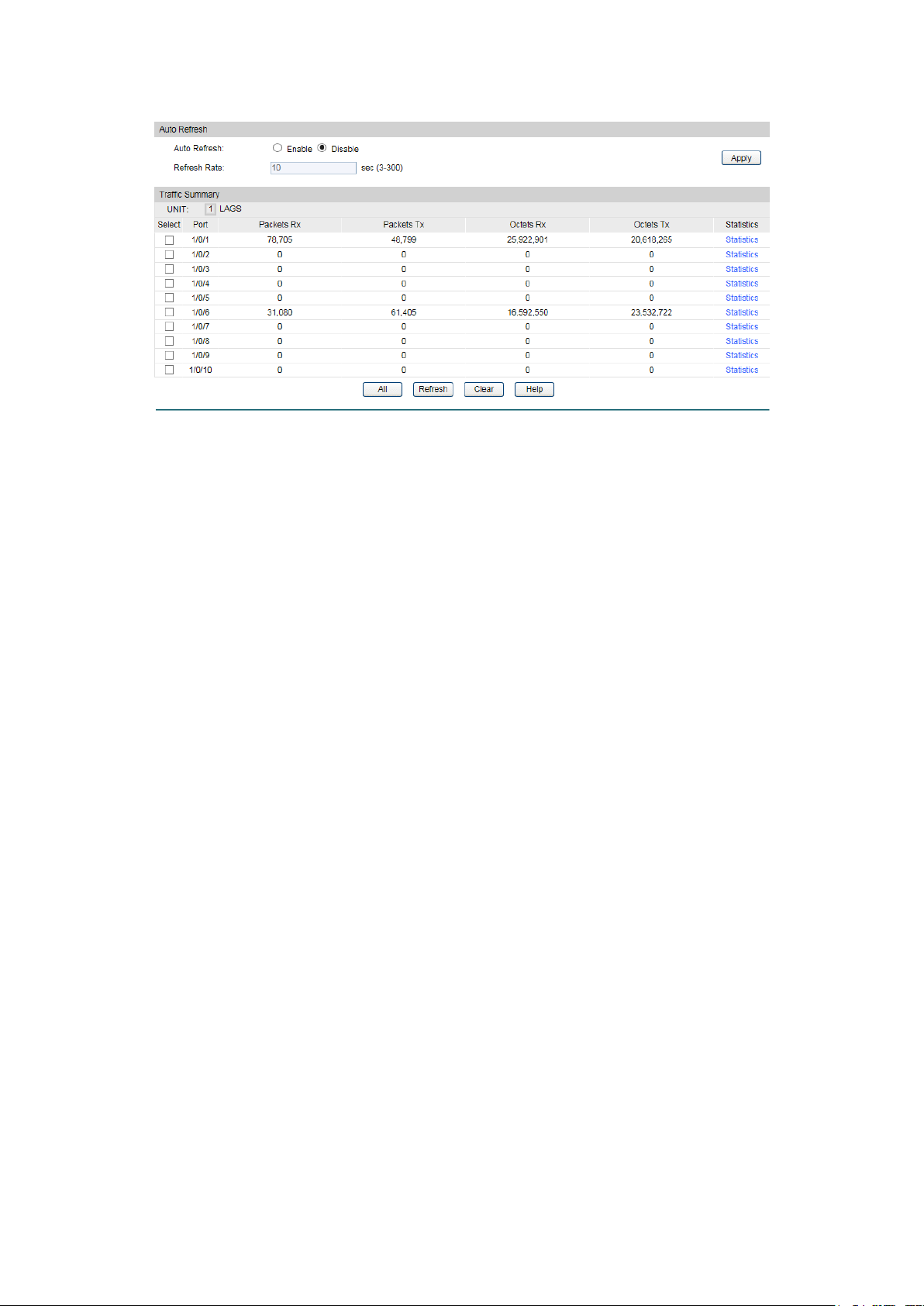
Auto Refresh
Traffic Summary
automatically.
Refresh Rate:
Enter a value in seconds to specify the refresh interval.
UNIT:1/LAGS:
to
show the information of the link aggregation groups
Select:
Select the desired port for clearing. It is multi-optional.
Port:
Displays the port number.
Packets Rx
Displays the number of packets received on the port. The error
packets are not counted in.
Packets Tx:
Displays the number of packets transmitted on the port.
Octets Rx
Displays the number of octets received on the port. The error
octets are counted in.
Octets Tx:
Displays the number of octets transmitted on the port.
Statistics
c statistics of
the port.
Choose the menu Switching→Traffic Monitor→Traffic Summary to load the following page.
Figure 5-12 Traffic Summary
The following entries are displayed on this screen:
Auto Refresh
Traffic Summary
:
:
: Allows you to Enable/Disable refreshing the
Click 1 to show the information of the physical ports. Click LAGS
: Click the Statistics button to view the detailed traffi
5.3.2 Traffic Statistics
Traffic Statistics screen displays the detailed traffic information of each port, which facilitates
you to monitor the traffic and locate faults promptly.
53
Page 64

Auto Refresh
ng the Traffic Summary
automatically.
Refresh Rate:
Enter a value in seconds to specify the refresh interval.
UNIT:1/LAGS:
to show the information of the physical ports. Click
LAGS to show the information of the link aggregation groups.
Port:
button or select the
port to view the traffic statistics of the corresponding port.
Received:
Displays the details of the packets received on the port.
Sent:
Displays the details of the packets transmitted on the port.
Broadcast
Displays the number of good broadcast packets received or
transmitted on the port. The error frames are not counted in.
Multicast
Displays the number of good multicast packets received or
transmitted on the port. The error frames are not counted in.
Unicast
Displays the number of good unicast packets received or
transmitted on the port. The error frames are not counted in.
Choose the menu Switching→Traffic Monitor→Traffic Statistics to load the following page.
Figure 5-13 Traffic Statistics
The following entries are displayed on this screen:
Auto Refresh
: Allows you to Enable/Disable refreshi
Port Select
Click 1
Enter a port number and click the Select
Statistics
:
:
:
54
Page 65

Alignment Errors
Displays the number of the received packets that have a bad
integral octet
(Alignment Error) and have a bad FCS with an integral octet
n 64 bytes and
bad
. The length of the packet is from
64 bytes to maximal bytes of the jumbo frame(usually 10240
bytes).
U
ndersizePkts:
Displays the number of the received packets (excluding error
packets) that are less than 64 bytes long.
Pkts64Octets
Displays the number of the received packets (including error
packets) that are 64 bytes long.
Pkts65to127Octets
the number of the received packets (including error
packets) that are between 65 and 127 bytes long.
Pkts128to255Octets
Displays the number of the received packets (including error
packets) that are between 128 and 255 bytes long.
Pkts256to511Octets
splays the number of the received packets (including error
packets) that are between 256 and 511 bytes long.
Pkts512to1023Octets
Displays the number of the received packets (including error
packets) that are between 512 and 1023 bytes long.
PktsOver1023
Displays the number of the received packets (including error
packets) that are over 1023 bytes.
Collisions
Displays the number of collisions experienced by a port during
packet transmissions.
:
: For T1500G-10MPS:
Frame Check Sequence (FCS) with a non-
(CRC Error). The length of the packet is betwee
1518 bytes.
For :
Displays the number of the received packets that have a
Frame Check Sequence (FCS)
: Displays
:
: Di
:
Octets:
:
5.4 MAC Address
The main function of the switch is forwarding the packets to the correct ports based on the
destination MAC address of the packets. Address Table contains the port-based MAC address
information, which is the base for the switch to forward packets quickly. The entries in the
Address Table can be updated by auto-learning or configured manually. Most the entries are
generated and updated by auto-learning. In the stable networks, the static MAC address
entries can facilitate the switch to reduce broadcast packets and enhance the efficiency of
packets forwarding remarkably. The address filtering feature allows the switch to filter the
undesired packets and forbid its forwarding so as to improve the network security.
55
Page 66

Being kept after
(if the configuration
is saved)
Relationship between the
bound MAC address and
The bound MAC address
be learned by the
VLAN.
Table
The bound MAC address
can be learned by the other
Table
The types and the features of the MAC Address Table are listed as the following:
Type
Static
Address
Table
Dynamic
Address
Filtering
Address
This function includes four submenus: Address Table, Static Address, Dynamic Address and
Filtering Address.
Configuration
Way
Manually
configuring
Automatically
learning
Manually
configuring
Table 5-1 Types and features of Address Table
Aging out
No Yes
Yes No
No Yes -
reboot
the port
cannot
other ports in the same
ports in the same VLAN.
5.4.1 Address Table
On this page, you can view all the information of the Address Table.
56
Page 67

MAC Address:
Enter the MAC address of your desired entry.
VLAN ID:
Enter the VLAN ID of your desired entry.
Type:
This option allows the address table to display all the
This option allows the address table to display the static
is option allows the address table to display the
This option allows the address table to display the
filtering address entries only.
Port: Select the corresponding port number or LAG of your desired
entry.
MAC Address:
Displays the MAC address learned by the switch.
Choose the menu Switching→MAC Address→Address Table to load the following page.
Figure 5-14 Address Table
The following entries are displayed on this screen:
Search Option
Select the type of your desired entry.
All:
address entries.
Static:
address entries only.
Dynamic: Th
dynamic address entries only.
Filter:
Address Table
57
Page 68

VLAN ID:
Displays the corresponding VLAN ID of the MAC address.
Port:
Displays the corresponding Port number of the MAC address.
Type:
Displays the type of the MAC address.
Aging Status:
Displays the aging status of the MAC address.
MAC Address:
Enter the static MAC Address to be bound.
VLAN ID:
Enter the corresponding VLAN ID of the MAC address.
Port:
Select the corresponding port of your desired entry.
5.4.2 Static Address
The static address table maintains the static address entries which can be added or removed
manually, independent of the aging time. In the stable networks, the static MAC address entries
can facilitate the switch to reduce broadcast packets and remarkably enhance the efficiency of
packets forwarding without learning the address. The static MAC address learned by the port
with Port Security enabled in the static learning mode will be displayed in the Static Address
Table.
Choose the menu Switching→MAC Address→Static Address to load the following page.
Figure 5-15 Static Address
The following entries are displayed on this screen:
Create Static Address
58
Page 69

Search Option:
down list and click the
in the Static Address
Port: Enter the Port number of your desired entry.
Select:
he corresponding port
number. It is multi-optional.
MAC Address:
Displays the static MAC Address.
VLAN ID:
Displays the corresponding VLAN ID of the MAC address.
Port: Displays the corresponding port number of the MAC address. Here
rt number to which the MAC address is
bound. The new port should be in the same VLAN.
Type:
Displays the type of the MAC address.
Aging Status:
Displays the aging status of the MAC address.
Search Option
Select a Search Option from the pull-
Static Address Table
Select the entry to delete or modify t
Search button to find your desired entry
Table.
MAC: Enter the MAC address of your desired entry.
VLAN ID: Enter the VLAN ID number of your desired entry.
you can modify the po
Note:
1. If the corresponding port number of the MAC address is not correct, or the connected port
(or the device) has been changed, the switch cannot forward the packets correctly. Please
reset the static address entry appropriately.
2. If the MAC address of a device has been added to the Static Address Table, connecting
the device to another port will cause its address not to be recognized dynamically by the
switch. Therefore, please ensure the entries in the Static Address Table are correct and
valid.
3. The MAC address in the Static Address Table cannot be added to the Filtering Address
Table or bound to a port dynamically.
5.4.3 Dynamic Address
The dynamic address can be generated by the auto-learning mechanism of the switch. The
Dynamic Address Table can update automatically by auto-learning or the MAC address aging
out mechanism.
To fully utilize the MAC address table, which has a limited capacity, the switch adopts an aging
mechanism for updating the table. That is, the switch removes the MAC address entries related
to a network device if no packet is received from the device within the aging time.
On this page, you can configure the dynamic MAC address entry.
59
Page 70

Auto Aging:
Allows you to Enable/Disable the Auto Aging feature.
Aging Time:
Enter the Aging Time for the dynamic address.
Search Option:
Search
Port: Enter the Port number of your desired entry.
Select: Select the entry to delete the dynamic address or to bind the MAC
address to the corresponding port statically. It is multi-optional.
MAC Address:
Displays the dynamic MAC Address.
VLAN ID:
Displays the corresponding VLAN ID of the MAC address.
Port:
Displays the corresponding port number of the MAC address.
Type:
Displays the type of the MAC address.
Choose the menu Switching→MAC Address→Dynamic Address to load the following page.
Figure 5-16 Dynamic Address
The following entries are displayed on this screen:
Aging Config
Search Option
Select a Search Option from the pull-down list and click the
button to find your desired entry in the Dynamic Address Table.
• MAC: Enter the MAC address of your desired entry.
• VLAN ID: Enter the VLAN ID number of your desired entry.
•
Dynamic Address Table
60
Page 71

Aging Status:
Displays the aging status of the MAC address.
Bind:
button to bind the MAC address of your selected
entry to the corresponding port statically.
MAC Address:
Enter the MAC Address to be filtered.
VLAN ID:
Enter the corresponding VLAN ID of the MAC address.
Search Option:
VLAN ID: Enter the VLAN ID number of your desired entry.
Click the Bind
Tips:
Setting aging time properly helps implement effective MAC address aging. The aging time that
is too long or too short results in a decrease of the switch performance. If the aging time is too
long, excessive invalid MAC address entries maintained by the switch may fill up the MAC
address table. This prevents the MAC address table from updating with network changes in
time. If the aging time is too short, the switch may remove valid MAC address entries. This
decreases the forwarding performance of the switch. It is recommended to keep the default
value.
5.4.4 Filtering Address
The filtering address is to forbid the undesired packets to be forwarded. The filtering address
can be added or removed manually, independent of the aging time. The filtering MAC address
allows the switch to filter the packets which includes this MAC address as the source address
or destination address, so as to guarantee the network security. The filtering MAC address
entries act on all the ports in the corresponding VLAN.
Choose the menu Switching→MAC Address→Filtering Address to load the following page.
Figure 5-17 Filtering Address
The following entries are displayed on this screen:
Create Filtering Address
Search Option
Select a Search Option from the pull-down list and click the Search
button to find your desired entry in the Filtering Address Table.
• MAC Address: Enter the MAC address of your desired entry.
•
61
Page 72

Select: Select the entry to delete the corresponding filtering address. It is
multi-optional.
MAC Address:
Displays the filtering MAC Address.
VLAN ID:
Displays the corresponding VLAN ID.
Port:
Here the symbol “--” indicates no specified port.
Type:
Displays the type of the MAC address.
Aging Status:
Displays the aging status of the MAC address.
Filtering Address Table
Note:
The MAC address in the Filtering Address Table cannot be added to the Static Address Table
or bound to a port dynamically.
Return to CONTENTS
62
Page 73

Chapter 6 VLAN
The traditional Ethernet is a data network communication technology based on CSMA/CD
(Carrier Sense Multiple Access/Collision Detect) via shared communication medium. Through
the traditional Ethernet, the overfull hosts in LAN will result in serious collision, flooding
broadcasts, poor performance or even breakdown of the Internet. Though connecting the
LANs through switches can avoid the serious collision, the flooding broadcasts cannot be
prevented, which will occupy plenty of bandwidth resources, causing potential serious security
problems.
A Virtual Local Area Network (VLAN) is a network topology configured according to a logical
scheme rather than the physical layout. The VLAN technology is developed for switches to
control broadcast in LANs. By creating VLANs in a physical LAN, you can divide the LAN into
multiple logical LANs, each of which has a broadcast domain of its own. Hosts in the same
VLAN communicate with one another as if they are in a LAN. However, hosts in different VLANs
cannot communicate with one another directly. Therefore, broadcast packets are limited in a
VLAN. Hosts in the same VLAN communicate with one another via Ethernet whereas hosts in
different VLANs communicate with one another through the Internet devices such as router,
the Layer 3 switch, etc. The following figure illustrates a VLAN implementation.
Figure 6-1 VLAN implementation
Compared with the traditional Ethernet, VLAN enjoys the following advantages.
(1) Broadcasts are confined to VLANs. This decreases bandwidth utilization and improves
network performance.
(2) Network security is improved. VLANs cannot communicate with one another directly.
That is, a host in a VLAN cannot access resources in another VLAN directly, unless
routers or Layer 3 switches are used.
(3) Network configuration workload for the host is reduced. VLAN can be used to group
specific hosts. When the physical position of a host changes within the range of the
VLAN, you do not need to change its network configuration.
63
Page 74
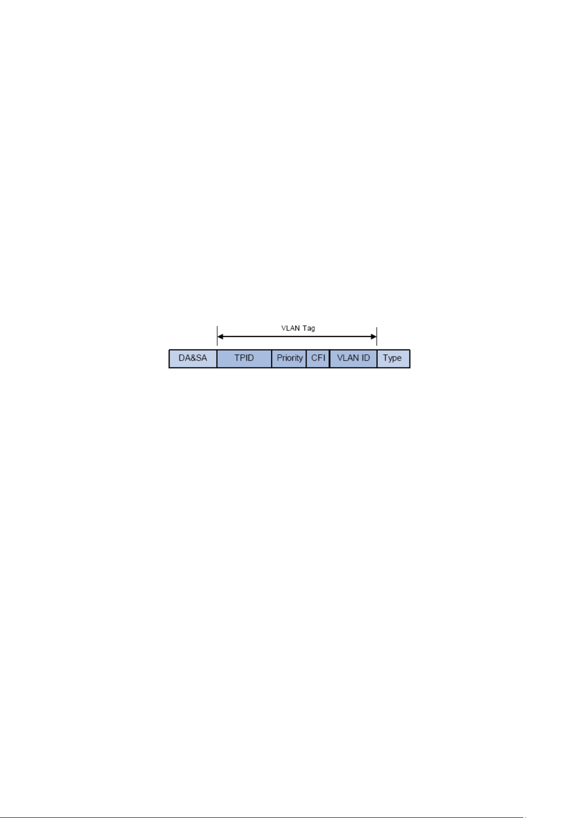
A VLAN can span across multiple switches, or even routers. This enables hosts in a VLAN to be
dispersed in a looser way. That is, hosts in a VLAN can belong to different physical network
segments. This switch supports 802.1Q VLAN to classify VLANs. VLAN tags in the packets are
necessary for the switch to identify packets of different VLANs.
6.1 802.1Q VLAN
VLAN tags in the packets are necessary for the switch to identify packets of different VLANs.
The switch works at the data link layer in OSI model and it can identify the data link layer
encapsulation of the packet only, so you can add the VLAN tag field into the data link layer
encapsulation for identification.
In 1999, IEEE issues the IEEE 802.1Q protocol to standardize VLAN implementation, defining
the structure of VLAN-tagged packets. IEEE 802.1Q protocol defines that a 4-byte VLAN tag is
encapsulated after the destination MAC address and source MAC address to show the
information about VLAN.
As shown in the following figure, a VLAN tag contains four fields, including TPID (Tag Protocol
Identifier), Priority, CFI (Canonical Format Indicator), and VLAN ID.
Figure 6-1 Format of VLAN Tag
(1) TPID: TPID is a 16-bit field, indicating that this data frame is VLAN-tagged. By default, it is
0x8100 in this switch.
(2) Priority: Priority is a 3-bit field, referring to 802.1p priority. Refer to section “QoS & QoS
profile” for details.
(3) CFI: CFI is a 1-bit field, indicating whether the MAC address is encapsulated in the
standard format in different transmission media. This field is not described in detail in this
chapter.
(4) VLAN ID: VLAN ID is a 12-bit field, indicating the ID of the VLAN to which this packet
belongs. It is in the range of 0 to 4,095. Generally, 0 and 4,095 is not used, so the field is in
the range of 1 to 4,094.
VLAN ID identifies the VLAN to which a packet belongs. When the switch receives a
un-VLAN-tagged packet, it will encapsulate a VLAN tag with the default VLAN ID of the inbound
port for the packet, and the packet will be assigned to the default VLAN of the inbound port for
transmission.
In this User Guide, the tagged packet refers to the packet with VLAN tag whereas the untagged
packet refers to the packet without VLAN tag, and the priority-tagged packet refers to the
packet with VLAN tag whose VLAN ID is 0.
Link Types of ports
When creating the 802.1Q VLAN, you should set the link type for the port according to its
connected device. The link types of port including the following two types: Untagged and
Tagged.
64
Page 75

Packets
Packets
Packets
When untagged
packets are
received, the
default VLAN
of the ingress
port, to the
is allowed by the
be forwarded
its VLAN tag
be forwarded
(1) Untagged: The untagged port can be added in multiple VLANs. If a VLAN-tagged
packet arrives at a port and the VLAN ID in its VLAN tag does not match any of the
VLAN the ingress port belongs to, this packet will be dropped. The packets forwarded
by the untagged port are untagged.
(2) Tagged: The tagged port can be added in multiple VLANs. If a VLAN-tagged packet
arrives at a port and the VLAN ID in its VLAN tag does not match any of the VLAN the
ingress port belongs to, this packet will be dropped. When the VLAN-tagged packets
are forwarded by the Tagged port, its VLAN tag will not be changed.
PVID
PVID (Port VLAN ID) is the default VID of the port. When the switch receives an
un-VLAN-tagged packet, it will add a VLAN tag to the packet according to the PVID of its
received port and forward the packets.
When creating VLANs, the PVID of each port, indicating the default VLAN to which the port
belongs, is an important parameter with the following two purposes:
(1) When the switch receives an un-VLAN-tagged packet, it will add a VLAN tag to the
packet according to the PVID of its received port
(2) PVID determines the default broadcast domain of the port, i.e. when the port receives
UL packets or broadcast packets, the port will broadcast the packets in its default
VLAN.
Different packets, tagged or untagged, will be processed in different ways, after being received
by ports of different link types, which is illustrated in the following table.
Receiving Packets Forwarding Packets
Port Type
Untagged
Tagged
Untagged
port will add the
tag, i.e. the PVID
packets.
Tagged Packets
If the VID of packet
port, the packet will
be received.
If the VID of packet
is forbidden by the
port, the packet will
be dropped.
Untagged
The packet will be
forwarded
unchanged.
The packet will be
forwarded with the
PVID of egress port
as its VLAN tag.
Tagged
The packet will
after removing
The packet will
with its current
VLAN tag.
IEEE 802.1Q VLAN function is implemented on the VLAN Config and Port Config pages.
6.1.1 VLAN Config
On this page, you can configure the 802.1Q VLAN and its ports.
Table 6-1 Relationship between Port Types and VLAN Packets Processing
65
Page 76

Select the desired entry to delete the corresponding VLAN. It is
multi-optional.
VLAN ID:
Displays the VLAN ID.
Name:
Displays the name of the specific VLAN.
Members:
Displays the port members in the VLAN.
Detail: Click to get the information of VLAN.
Choose the menu VLAN→802.1Q VLAN→VLAN Config to load the following page.
Figure 6-2 VLAN Table
To ensure the normal communication of the factory switch, the default VLAN of all ports is set
to VLAN1.
The following entries are displayed on this screen:
VLAN Table
Select:
Operation: Allows you to view or modify the information for each entry.
• Edit: Click to modify the settings of VLAN.
•
Click Edit and the following content will be shown.
Figure 6-3 VLAN Info
66
Page 77
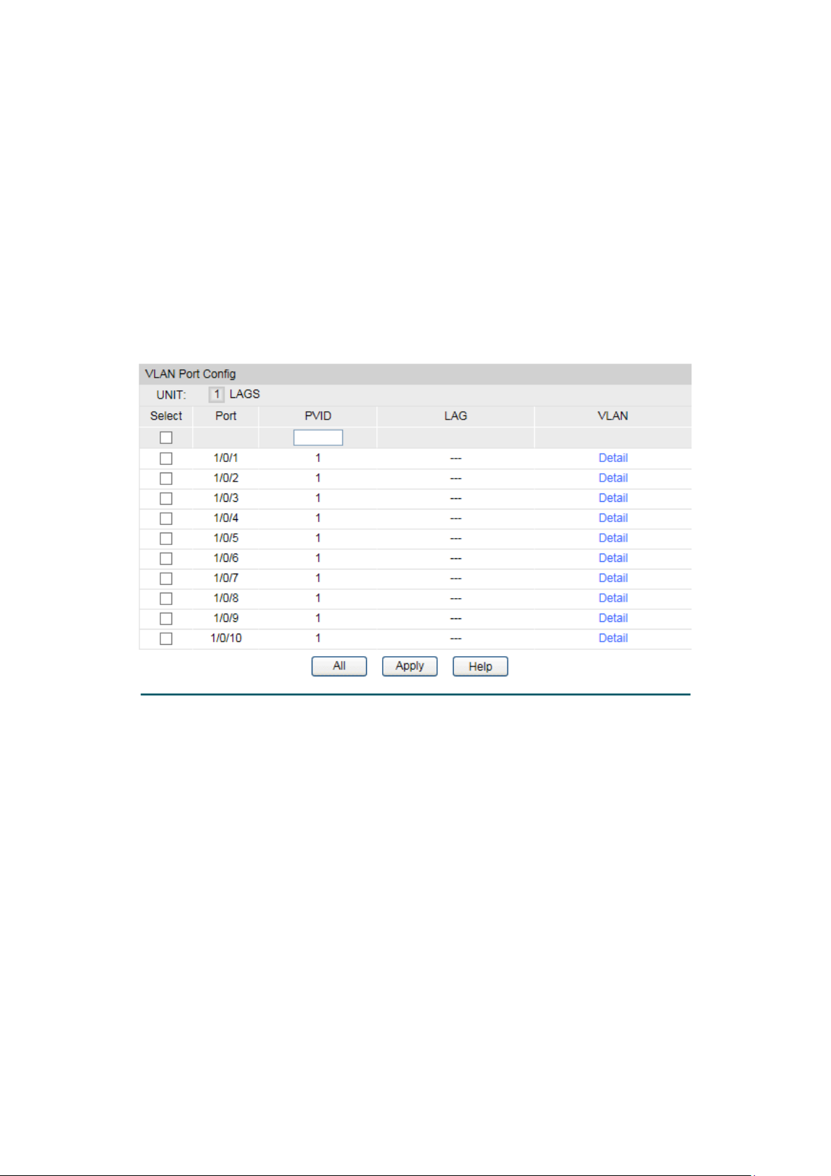
VLAN ID:
Displays the ID number of VLAN.
Name:
Displays the name of the specific VLAN.
Untagged Port:
Displays the untagged ports of the specific VLAN.
Tagged Port:
Displays the tagged ports of the specific VLAN.
to configure
the link aggregation groups.
Select:
PVID:
Enter the PVID number of the port.
LAG:
Displays the LAG to which the port belongs.
button to view the information of the VLAN to
which the port belongs.
VLAN Info
6.1.2 Port Config
Before creating the 802.1Q VLAN, please acquaint yourself with all the devices connected to
the switch in order to configure the ports properly.
Choose the menu VLAN→802.1Q VLAN→Port Config to load the following page.
Figure 6-4 Port Config
The following entries are displayed on this screen:
VLAN Port Config
UNIT:1/LAGS: Click 1 to configure the physical ports. Click LAGS
Select the desired port for configuration. It is multi-optional.
Port:
Displays the port number.
VLAN: Click the Detail
67
Page 78
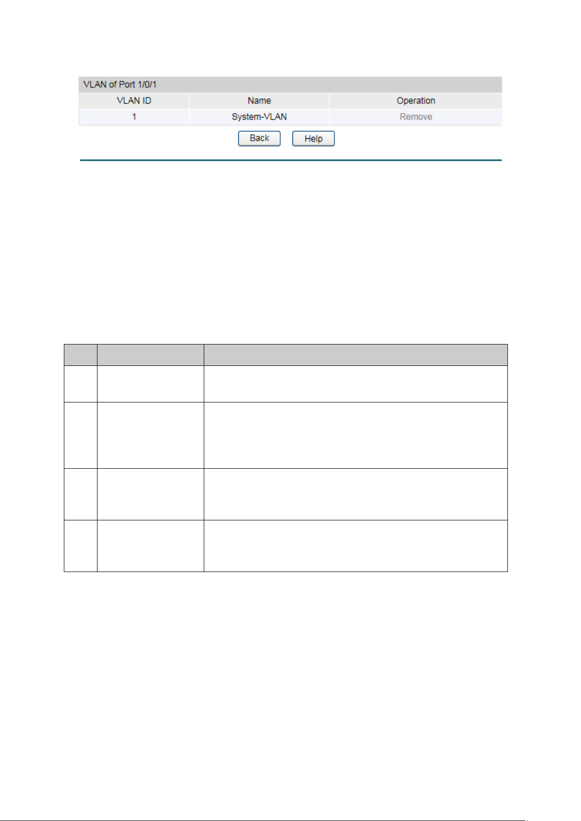
VLAN ID:
Name:
Operation:
Allows you to remove the port from the current VLAN.
Step
Operation
Description
port.
the link type for the port basing on its connected device.
and the description for the VLAN. Meanwhile, specify its
member ports.
the corresponding VLAN.
clicking the Delete button.
Click the Detail button to view the information of the corresponding VLAN.
Figure 6-5 View the Current VLAN of Port
The following entries are displayed on this screen:
VLAN of Port
Displays the ID number of VLAN.
Displays the user-defined description of VLAN.
Configuration Procedure:
1 Set the link type for
2 Create VLAN. Required. On the VLAN→802.1Q VLAN→VLAN Config page,
3 Modify/View VLAN. Optional. On the VLAN→802.1Q VLAN→VLAN Config page,
4 Delete VLAN Optional. On the VLAN→802.1Q VLAN→VLAN Config page,
Required. On the VLAN→802.1Q VLAN→Port Config page, set
click the Create button to create a VLAN. Enter the VLAN ID
click the Edit/Detail button to modify/view the information of
select the desired entry to delete the corresponding VLAN by
6.2 Application Example for 802.1Q VLAN
Network Requirements
Switch A is connecting to PC A and Server B;
Switch B is connecting to PC B and Server A;
PC A and Server A is in the same VLAN;
PC B and Server B is in the same VLAN;
PCs in the two VLANs cannot communicate with each other.
68
Page 79
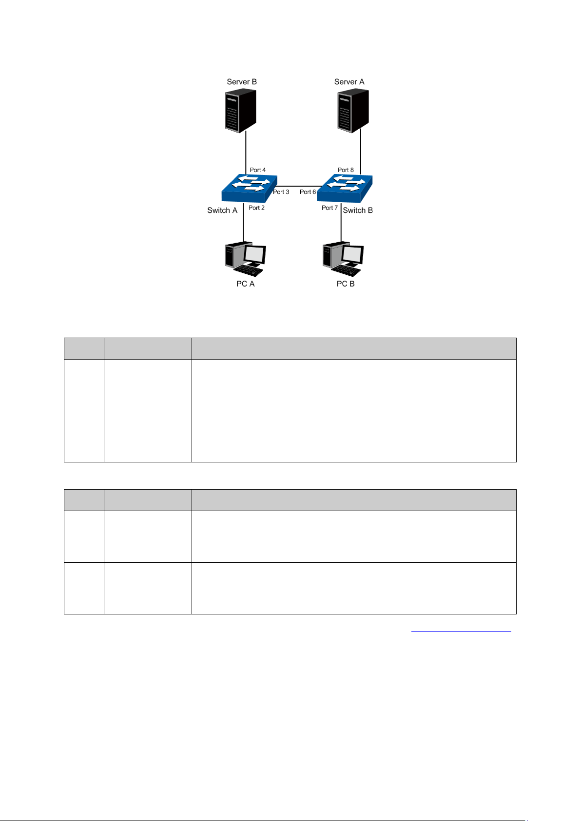
Network Diagram
Step
Operation
Description
Port 3.
Port 4.
Step
Operation
Description
Port 8.
Port 7.
Configuration Procedure
Configure switch A
1
2
Configure switch B
1
2
Create VLAN10 Required. On VLAN→802.1Q VLAN→VLAN Config page, create a
Create VLAN20 Required. On VLAN→802.1Q VLAN→VLAN Config page, create a
Create VLAN10 Required. On VLAN→802.1Q VLAN→VLAN Config page, create a
Create VLAN20 Required. On VLAN→802.1Q VLAN→VLAN Config page, create a
VLAN with its VLAN ID as 10, owning Untagged Port 2 and Tagged
VLAN with its VLAN ID as 20, owning Tagged Port 3 and Untagged
VLAN with its VLAN ID as 10, owning Tagged Port 6 and Untagged
VLAN with its VLAN ID as 20, owning Tagged Port 6 and Untagged
Return to CONTENTS
69
Page 80

Chapter 7 Spanning Tree
STP (Spanning Tree Protocol), subject to IEEE 802.1D standard, is to disbranch a ring network in
the Data Link layer in a local network. Devices running STP discover loops in the network and
block ports by exchanging information, in that way, a ring network can be disbranched to form a
tree-topological ring-free network to prevent packets from being duplicated and forwarded
endlessly in the network.
BPDU (Bridge Protocol Data Unit) is the protocol data that STP and RSTP use. Enough
information is carried in BPDU to ensure the spanning tree generation. STP is to determine the
topology of the network via transferring BPDUs between devices.
To implement spanning tree function, the switches in the network transfer BPDUs between
each other to exchange information and all the switches supporting STP receive and process
the received BPDUs. BPDUs carry the information that is needed for switches to figure out the
spanning tree.
STP Elements
Bridge ID(Bridge Identifier): Indicates the value of the priority and MAC address of the bridge.
Bridge ID can be configured and the switch with the lower bridge ID has the higher priority.
Root Bridge: Indicates the switch has the lowest bridge ID. Configure the best PC in the ring
network as the root bridge to ensure best network performance and reliability.
Designated Bridge: Indicates the switch has the lowest path cost from the switch to the root
bridge in each network segment. BPDUs are forwarded to the network segment through the
designated bridge. The switch with the lowest bridge ID will be chosen as the designated
bridge.
Root Path Cost: Indicates the sum of the path cost of the root port and the path cost of all the
switches that packets pass through. The root path cost of the root bridge is 0.
Bridge Priority: The bridge priority can be set to a value in the range of 0 to 32768. The lower
value priority has the higher priority. The switch with the higher priority has more chance to be
chosen as the root bridge.
Root Port: Indicates the port that has the lowest path cost from this bridge to the Root Bridge
and forwards packets to the root.
Designated Port: Indicates the port that forwards packets to a downstream network segment
or switch.
Port Priority: The port priority can be set to a value in the range of 0 to 255. The lower value
priority has the higher priority. The port with the higher priority has more chance to be chosen
as the root port.
Path Cost: Indicates the parameter for choosing the link path by STP. By calculating the path
cost, STP chooses the better links and blocks the redundant links so as to disbranch the
ring-network to form a tree-topological ring-free network.
The following network diagram shows the sketch map of spanning tree. Switch A, B and C are
connected together in order. After STP generation, switch A is chosen as root bridge, the path
from port 2 to port 6 is blocked.
70
Page 81

Bridge: Switch A is the root bridge in the whole network; switch B is the designated bridge of
switch C.
Port: Port 3 is the root port of switch B and port 5 is the root port of switch C; port 1 is the
designated port of switch A and port 4 is the designated port of switch B; port 6 is the
blocked port of switch C.
Figure 7-1 Basic STP diagram
STP Timers
Hello Time:
Hello Time ranges from 1 to 10 seconds. It specifies the interval to send BPDU packets. It is
used to test the links.
Max. Age:
Max. Age ranges from 6 to 40 seconds. It specifies the maximum time the switch can wait
without receiving a BPDU before attempting to reconfigure.
Forward Delay:
Forward Delay ranges from 4 to 30 seconds. It specifies the time for the port to transit its state
after the network topology is changed.
When the STP regeneration caused by network malfunction occurs, the STP structure will get
some corresponding change. However, as the new configuration BPDUs cannot be spread in
the whole network at once, the temporal loop will occur if the port transits its state immediately.
Therefore, STP adopts a state transit mechanism, that is, the new root port and the designated
port begins to forward data after twice forward delay, which ensures the new configuration
BPDUs are spread in the whole network.
BPDU Comparing Principle in STP mode
Assuming two BPDUs: BPDU X and BPDU Y
If the root bridge ID of X is smaller than that of Y, X is superior to Y.
If the root bridge ID of X equals that of Y, but the root path cost of X is smaller than that of Y, X
is superior to Y.
71
Page 82

Step
Operation
If the priority of the BPDU received on the port is lower than that of the BPDU if
of the port itself, the switch discards the BPDU and does not change the BPDU
of the port.
iority of the BPDU is higher than that of the BPDU of the port itself, the
switch replaces the BPDU of the port with the received one and compares it
with those of other ports on the switch to obtain the one with the highest
priority.
Step
Operation
For each switch (except the one chosen as the root bridge) in a network, the
port that receives the BPDU with the highest priority is chosen as the root port
of the switch.
st, the switch generates a
Root path is replaced with the sum of the root path cost of the root port
The ID of the designated port is replaced with that of the port.
If the root bridge ID and the root path cost of X equal those of Y, but the bridge ID of X is
smaller than that of Y, X is superior to Y.
If the root bridge ID, the root path cost and bridge ID of X equal those of Y, but the port ID of X
is smaller than that of Y, X is superior to Y.
STP Generation
In the beginning
In the beginning, each switch regards itself as the root, and generates a configuration BPDU for
each port on it as a root, with the root path cost being 0, the ID of the designated bridge being
that of the switch, and the designated port being itself.
Comparing BPDUs
Each switch sends out configuration BPDUs and receives a configuration BPDU on one of its
ports from another switch. The following table shows the comparing operations.
1
2 If the pr
Table 7-1 Comparing BPDUs
Selecting the root bridge
The root bridge is selected by BPDU comparing. The switch with the smallest root ID is chosen
as the root bridge.
Selecting the root port and designate port
The operation is taken in the following way:
1
2 Using the root port BPDU and the root path co
designated port BPDU for each of its ports.
Root ID is replaced with that of the root port;
and the path cost between this port and the root port;
The ID of the designated bridge is replaced with that of the switch;
72
Page 83

The switch compares the resulting BPDU with the BPDU of the desired port
PDU takes the precedence over the BPDU of the port, the
port is chosen as the designated port and the BPDU of this port is
replaced with the resulting BPDU. The port regularly sends out the
the resulting BPDU, the
BPDU of this port is not replaced and the port is blocked. The port only can
receive BPDUs.
3
whose role you want to determine.
If the resulting B
resulting BPDU;
If the BPDU of this port takes the precedence over
Table 7-2 Selecting root port and designated port
Tips:
In a STP with stable topology, only the root port and designated port can forward data, and the
other ports are blocked. The blocked ports only can receive BPDUs.
RSTP (Rapid Spanning Tree Protocol), evolved from the 802.1D STP standard, enable Ethernet
ports to transit their states rapidly. The premises for the port in the RSTP to transit its state
rapidly are as follows.
The condition for the root port to transit its port state rapidly: The old root port of the
switch stops forwarding data and the designated port of the upstream switch begins to
forward data.
The condition for the designated port to transit its port state rapidly: The designated
port is an edge port or connecting to a point-to-point link. If the designated port is an
edge port, it can directly transit to forwarding state; if the designated port is connecting
to a point-to-point link, it can transit to forwarding state after getting response from the
downstream switch through handshake.
RSTP Elements
Edge Port: Indicates the port connected directly to terminals.
P2P Link: Indicates the link between two switches directly connected.
MSTP (Multiple Spanning Tree Protocol), compatible with both STP and RSTP and subject to
IEEE 802.1s standard, not only enables spanning trees to converge rapidly, but also enables
packets of different VLANs to be forwarded along their respective paths so as to provide
redundant links with a better load-balancing mechanism.
Features of MSTP:
MSTP combines VLANs and spanning tree together via VLAN-to-instance mapping table.
It binds several VLANs to an instance to save communication cost and network
resources.
MSTP divides a spanning tree network into several regions. Each region has several
internal spanning trees, which are independent of each other.
MSTP provides a load-balancing mechanism for the packets transmission in the VLAN.
MSTP is compatible with both STP and RSTP.
73
Page 84

MSTP Elements
MST Region (Multiple Spanning Tree Region): An MST Region comprises switches with the
same region configuration and VLAN-to-Instances mapping relationship.
IST (Internal Spanning Tree): An IST is a spanning tree in an MST.
CST (Common Spanning Tree): A CST is the spanning tree in a switched network that connects
all MST regions in the network.
CIST (Common and Internal Spanning Tree): A CIST, comprising IST and CST, is the spanning
tree in a switched network that connects all switches in the network.
The following figure shows the network diagram in MSTP.
Figure 7-2 Basic MSTP diagram
MSTP
MSTP divides a network into several MST regions. The CST is generated between these MST
regions, and multiple spanning trees can be generated in each MST region. Each spanning tree
is called an instance. As well as STP, MSTP uses BPDUs to generate spanning tree. The only
difference is that the BPDU for MSTP carries the MSTP configuration information on the
switches.
Port States
In an MSTP, ports can be in the following four states:
Forwarding: In this status the port can receive/forward data, receive/send BPDU packets
as well as learn MAC address.
Learning: In this status the port can receive/send BPDU packets and learn MAC address.
Blocking: In this status the port can only receive BPDU packets.
Disconnected: In this status the port is not participating in the STP.
Port Roles
In an MSTP, the following roles exist:
74
Page 85

Root Port: Indicates the port that has the lowest path cost from this bridge to the Root
Bridge and forwards packets to the root.
Designated Port: Indicates the port that forwards packets to a downstream network
segment or switch.
Master Port: Indicates the port that connects a MST region to the common root. The path
from the master port to the common root is the shortest path between this MST region
and the common root.
Alternate Port: Indicates the port that can be a backup port of a root or master port.
Backup Port: Indicates the port that is the backup port of a designated port.
Disabled: Indicates the port that is not participating in the STP.
The following diagram shows the different port roles.
Figure 7-3 Port roles
The Spanning Tree module is mainly for spanning tree configuration of the switch, including
four submenus: STP Config, Port Config, MSTP Instance and STP Security.
7.1 STP Config
The STP Config function, for global configuration of spanning trees on the switch, can be
implemented on STP Config and STP Summary pages.
7.1.1 STP Config
Before configuring spanning trees, you should make clear the roles each switch plays in each
spanning tree instance. Only one switch can be the root bridge in each spanning tree instance.
On this page you can globally configure the spanning tree function and related parameters.
Choose the menu Spanning Tree→STP Config→STP Config to load the following page.
75
Page 86

STP:
Select Enable/Disable STP function globally on the switch.
MSTP: Multiple Spanning Tree Protocol.
Enter a value from 0 to 61440 to specify the priority of the
the switch with the highest priority will be chosen as the root
is 32768 and should be exact divisor of 4096.
≤ Max Age. The default value is 2 seconds.
time the switch can wait without receiving a BPDU before
attempting to reconfigure. The default value is 20 seconds.
2*(Forward Delay-1) ≥ Max Age. The default value is 15 seconds.
5pps.
that occur in a specific region before the BPDU is discarded.
The default value is 20 hops.
Figure 7-4 STP Config
The following entries are displayed on this screen:
Global Config
Version: Select the desired STP version on the switch.
STP: Spanning Tree Protocol.
RSTP: Rapid Spanning Tree Protocol.
Parameters Config
CIST Priority:
switch for comparison in the CIST. CIST priority is an important
criterion on determining the root bridge. In the same condition,
bridge. The lower value has the higher priority. The default value
Hello Time Enter a value from 1 to 10 in seconds to specify the interval to
send BPDU packets. It is used to test the links. 2*(Hello Time + 1)
Max Age: Enter a value from 6 to 40 in seconds to specify the maximum
Forward Delay: Enter a value from 4 to 30 in seconds to specify the time for the
port to transit its state after the network topology is changed.
TxHold Count: Enter a value from 1 to 20 to set the maximum number of BPDU
packets transmitted per Hello Time interval. The default value is
Max Hops: Enter a value from 1 to 40 to set the maximum number of hops
76
Page 87

Note:
1. The forward delay parameter and the network diameter are correlated. A too small forward
delay parameter may result in temporary loops. A too large forward delay may cause a
network unable to resume the normal state in time. The default value is recommended.
2. An adequate hello time parameter can enable the switch to discover the link failures
occurred in the network without occupying too much network resources. A too large hello
time parameter may result in normal links being regarded as invalid when packets drop
occurred in the links, which in turn result in spanning tree being regenerated. A too small
hello time parameter may result in duplicated configuration being sent frequently, which
increases the network load of the switches and wastes network resources. The default
value is recommended.
3. A too small max age parameter may result in the switches regenerating spanning trees
frequently and cause network congestions to be falsely regarded as link problems. A too
large max age parameter result in the switches unable to find the link problems in time,
which in turn handicaps spanning trees being regenerated in time and makes the network
less adaptive. The default value is recommended.
4. If the TxHold Count parameter is too large, the number of MSTP packets being sent in each
hello time may be increased with occupying too much network resources. The default
value is recommended.
7.1.2 STP Summary
On this page you can view the related parameters for Spanning Tree function.
Choose the menu Spanning Tree→STP Config→STP Summary to load the following page.
77
Page 88
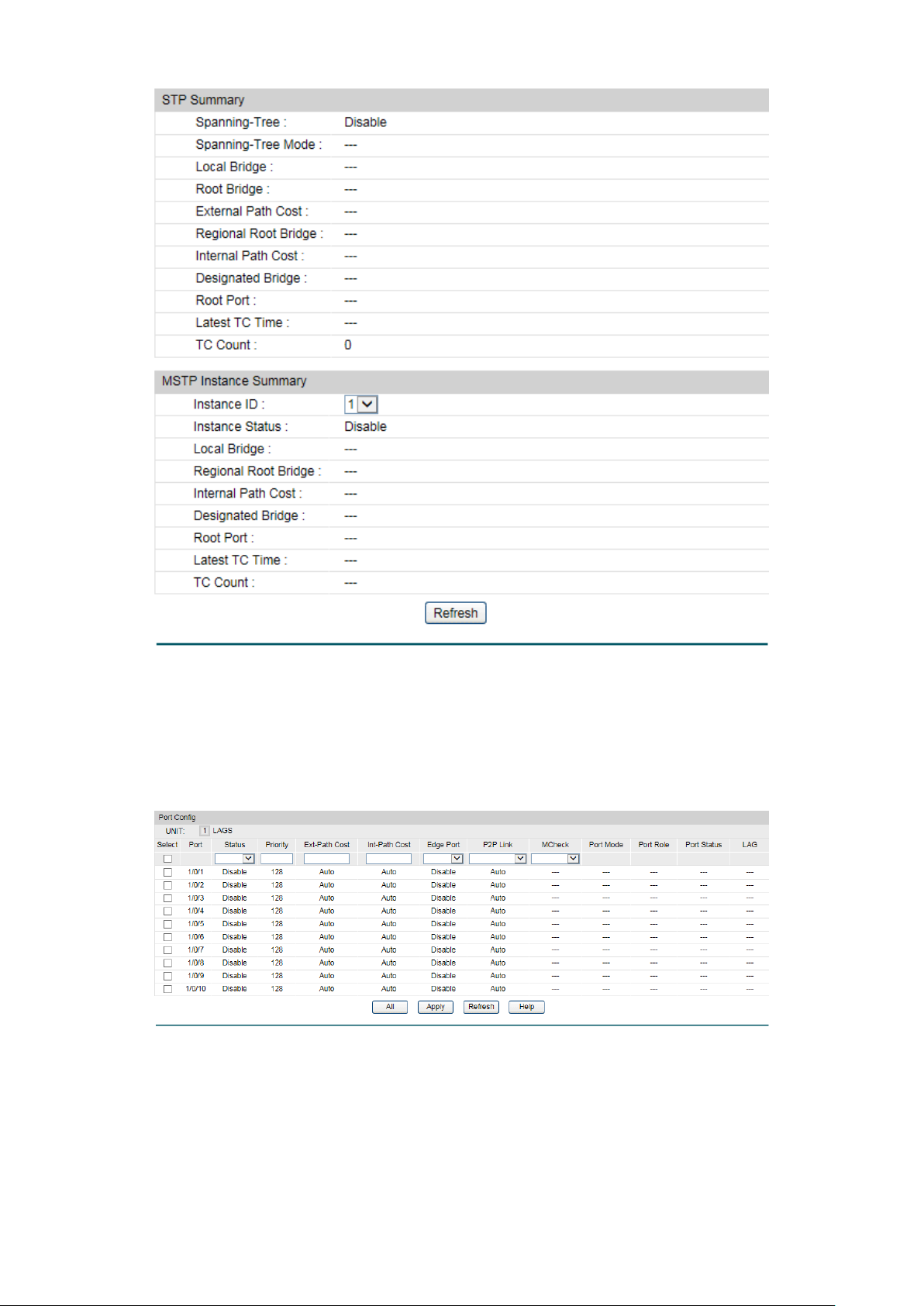
select the corresponding port
based on the port number you entered.
Figure 7-5 STP Summary
7.2 Port Config
On this page you can configure the parameters of the ports for CIST
Choose the menu Spanning Tree→Port Config to load the following page.
Figure 7-6 Port Config
The following entries are displayed on this screen:
Port Config
Port Select: Click the Select button to quick-
78
Page 89

Select:
Select the desired port for STP configuration. It is multi-optional.
Port:
Displays the port number of the switch.
Status:
Select Enable /Disable STP function for the desired port.
Enter a value from 0 to 240 divisible by 16. Port priority is an
important criterion on determining if the port connected to this
priority.
ExtPath Cost is used to choose the path and calculate the path
on determining the root port. The lower value has the higher
priority.
determining the root port. The lower value has the higher priority.
Select Enable/Disable Edge Port. The edge port can transit its
forwarding rapidly without waiting for
forward delay.
rapidly to reduce the unnecessary forward delay.
means no MCheck operation.
STP Version:
Displays the STP version of the port.
the common root. The path from the master port to the
Disabled: Indicates the port that is not participating in the STP.
Learning: In this status the port can receive/send BPDU
packets and learn MAC address.
Priority:
port will be chosen as the root port. The lower value has the higher
ExtPath:
costs of ports in different MST regions. It is an important criterion
IntPath: IntPath Cost is used to choose the path and calculate the path
costs of ports in an MST region. It is an important criterion on
Edge Port:
state from blocking to
P2P Link: Select the P2P link status. If the two ports in the P2P link are root
port or designated port, they can transit their states to forwarding
MCheck: Select Enable to perform MCheck operation on the port. Unchange
Port Role: Displays the role of the port played in the STP Instance.
Root Port: Indicates the port that has the lowest path cost
from this bridge to the Root Bridge and forwards packets to
the root.
Designated Port: Indicates the port that forwards packets to a
downstream network segment or switch.
Master Port: Indicates the port that connects a MST region to
common root is the shortest path between this MST region
and the common root.
Alternate Port: Indicates the port that can be a backup port of
a root or master port.
Backup Port: Indicates the port that is the backup port of a
designated port.
Port Status: Displays the working status of the port.
Forwarding: In this status the port can receive/forward data,
receive/send BPDU packets as well as learn MAC address.
79
Page 90
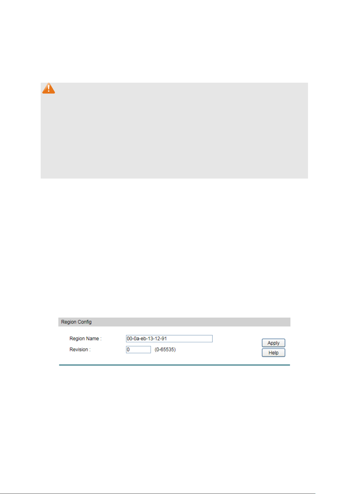
Blocking: In this status the port can only receive BPDU
STP.
LAG:
Displays the LAG number which the port belongs to.
up to 32
characters.
Revision:
Enter the revision from 0 to 65535 for MST region identification.
packets.
Disconnected: In this status the port is not participating in the
Note:
1. Configure the ports connected directly to terminals as edge ports and enable the BPDU
protection function as well. This not only enables these ports to transit to forwarding state
rapidly but also secures your network.
2. All the links of ports in a LAG can be configured as point-to-point links.
3. When the link of a port is configured as a point-to-point link, the spanning tree instances
owning this port are configured as point-to-point links. If the physical link of a port is not a
point-to-point link and you forcibly configure the link as a point-to-point link, temporary
loops may be incurred.
7.3 MSTP Instance
MSTP combines VLANs and spanning tree together via VLAN-to-instance mapping table
(VLAN-to-spanning-tree mapping). By adding MSTP instances, it binds several VLANs to an
instance to realize the load balance based on instances.
Only when the switches have the same MST region name, MST region revision and
VLAN-to-Instance mapping table, the switches can be regarded as in the same MST region.
The MSTP Instance function can be implemented on Region Config, Instance Config and
Instance Port Config pages.
7.3.1 Region Config
On this page you can configure the name and revision of the MST region
Choose the menu Spanning Tree→MSTP Instance→Region Config to load the following page.
Figure 7-7 Region Config
The following entries are displayed on this screen:
Region Config
Region Name: Create a name for MST region identification using
80
Page 91

Instance ID:
Enter the corresponding instance ID.
VLAN ID won’t be replaced.
Select:
Select the desired Instance ID for configuration. It is multi-optional.
Instance ID:
Displays Instance ID of the switch.
Status:
Displays status of the instance.
bridge in the specific instance.
and mapped to the CIST.
7.3.2 Instance Config
Instance Configuration, a property of MST region, is used to describe the VLAN to Instance
mapping configuration. You can assign VLAN to different instances appropriate to your needs.
Every instance is a VLAN group independent of other instances and CIST.
Choose the menu Spanning Tree→MSTP Instance→Instance Config to load the following
page.
Figure 7-8 Instance Config
The following entries are displayed on this screen:
VLAN-Instance Mapping
VLAN ID: Enter the desired VLAN ID. After modification here, the new VLAN
ID will be added to the corresponding instance ID and the previous
Instance Table
Priority: Enter the priority of the switch in the instance. It is an important
criterion on determining if the switch will be chosen as the root
VLAN ID: Enter the VLAN ID which belongs to the corresponding instance
ID. After modification here, the previous VLAN ID will be cleared
81
Page 92

cleared VLAN ID will be automatically mapped to the CIST.
Instance ID:
Select the desired instance ID for its port configuration.
link aggregation groups.
multi-optional.
Port:
Displays the port number of the switch.
Enter the priority of the port in the instance. It is an important
chosen as the root port.
Clear All: Click Clear All to clear up all VLAN IDs from the instance ID. The
7.3.3 Instance Port Config
A port can play different roles in different spanning tree instance. On this page you can
configure the parameters of the ports in different instance IDs as well as view status of the
ports in the specified instance.
Choose the menu Spanning Tree→MSTP Instance→Instance Port Config to load the
following page.
Figure 7-9 Instance Port Config
The following entries are displayed on this screen:
Instance ID Select
Instance Port Config
UNIT:1/LAGS: Click 1 to configure the physical ports. Click LAGS to configure the
Select: Select the desired port to specify its priority and path cost. It is
Priority:
criterion on determining if the port connected to this port will be
82
Page 93

of ports in an MST region. It is an important criterion on
determining the root port. The lower value has the higher priority.
Port Role:
Displays the role of the port played in the MSTP Instance.
Port Status:
Displays the working status of the port.
LAG:
Displays the LAG number which the port belongs to.
Step
Operation
Description
play in spanning tree
instances: root bridge or
designated bridge
Globally configure MSTP
Tree→STP Config→STP Config page.
Configure MSTP parameters
for ports
Configure MSTP parameters for ports on
Spanning Tree→Port Config→Port Config page.
Required. Create MST region and configure the role
Config page.
Configure MSTP parameters
Optional. Configure different instances in the MST
Port Config page.
Path Cost: Path Cost is used to choose the path and calculate the path costs
Note:
The port status of one port in different spanning tree instances can be different.
Global configuration Procedure for Spanning Tree function:
1 Make clear roles the switches
2
parameters
3
4 Configure the MST region
5
for instance ports
Preparation.
Required. Enable Spanning Tree function on the switch
and configure MSTP parameters on Spanning
Required.
the switch plays in the MST region on Spanning
Tree→MSTP Instance→Region Config and Instance
region and configure MSTP parameters for instance
ports on Spanning Tree→MSTP Instance→Instance
7.4 STP Security
Configuring protection function for devices can prevent devices from any malicious attack
against STP features. The STP Security function can be implemented on Port Protect page.
Port Protect function is to prevent the devices from any malicious attack against STP features.
7.4.1 Port Protect
On this page you can configure loop protect feature, root protect feature, TC protect feature,
BPDU protect feature and BPDU filter feature for ports. You are suggested to enable
corresponding protection feature for the qualified ports.
83
Page 94

Loop Protect
In a stable network, a switch maintains the states of ports by receiving and processing BPDU
packets from the upstream switch. However, when link congestions or link failures occurred to
the network, a down stream switch does not receive BPDU packets for certain period, which
results in spanning trees being regenerated and roles of ports being reselected, and causes
the blocked ports to transit to forwarding state. Therefore, loops may be incurred in the
network.
The loop protect function can suppresses loops. With this function enabled, a port, regardless
of the role it plays in instances, is always set to blocking state, when the port does not receive
BPDU packets from the upstream switch and spanning trees are regenerated, and thereby
loops can be prevented.
Root Protect
A CIST and its secondary root bridges are usually located in the high-bandwidth core region.
Wrong configuration or malicious attacks may result in configuration BPDU packets with higher
priorities being received by the legal root bridge, which causes the current legal root bridge to
lose its position and network topology jitter to occur. In this case, flows that should travel along
high-speed links may lead to low-speed links, and network congestion may occur.
To avoid this, MSTP provides root protect function. Ports with this function enabled can only be
set as designated ports in all spanning tree instances. When a port of this type receives BDPU
packets with higher priority, it transits its state to blocking state and stops forwarding packets
(as if it is disconnected from the link). The port resumes the normal state if it does not receive
any configuration BPDU packets with higher priorities for a period of two times of forward
delay.
TC Protect
A switch removes MAC address entries upon receiving TC-BPDU packets. If a user maliciously
sends a large amount of TC-BPDU packets to a switch in a short period, the switch will be busy
with removing MAC address entries, which may decrease the performance and stability of the
network.
To prevent the switch from frequently removing MAC address entries, you can enable the TC
protect function on the switch. With TC protect function enabled, if the account number of the
received TC-BPDUs exceeds the maximum number you set in the TC threshold field, the switch
will not performs the removing operation in the TC protect cycle. Such a mechanism prevents
the switch from frequently removing MAC address entries.
BPDU Protect
Ports of the switch directly connected to PCs or servers are configured as edge ports to
rapidly transit their states. When these ports receive BPDUs, the system automatically
configures these ports as non-edge ports and regenerates spanning trees, which may cause
network topology jitter. Normally these ports do not receive BPDUs, but if a user maliciously
attacks the switch by sending BPDUs, network topology jitter occurs.
To prevent this attack, MSTP provides BPDU protect function. With this function enabled on the
switch, the switch shuts down the edge ports that receive BPDUs and reports these cases to
the administrator. If a port is shut down, only the administrator can restore it.
84
Page 95

link aggregation groups.
Select the desired port for port protect configuration. It is
multi-optional.
Port:
Displays the port number of the switch.
recalculating STP because of link failures and network
congestions.
by the role change of the current legal root bridge.
crease of the performance and
stability of the switch brought by continuously removing MAC
address entries upon receiving TC-BPDUs in the STP network.
BPDU Filter
BPDU filter function is to prevent BPDUs flood in the STP network. If a switch receives
malicious BPDUs, it forwards these BPDUs to the other switched in the network, which may
result in spanning trees being continuously regenerated. In this case, the switch occupying too
much CPU or the protocol status of BPDUs is wrong.
With BPDU filter function enabled, a port does not receive or forward BPDUs, but it sends out
its own BPDUs. Such a mechanism prevents the switch from being attacked by BPDUs so as to
guarantee generation the spanning trees correct.
Choose the menu Spanning Tree→STP Security→Port Protect to load the following page.
Figure 7-10 Port Protect
The following entries are displayed on this screen:
Port Protect
UNIT:1/LAGS: Click 1 to configure the physical ports. Click LAGS to configure the
Select:
Loop Protect: Loop Protect is to prevent the loops in the network brought by
Root Protect: Root Protect is to prevent wrong network topology change caused
TC Protect: TC Protect is to prevent the de
85
Page 96

maliciously created BPDUs
BPDU Filter:
BPDU Filter is to prevent BPDUs flood in the STP network.
LAG:
Displays the LAG number which the port belongs to.
Step
Operation
Description
page, configure the link
106. The detailed
VLAN.
BPDU Protect: BPDU Protect is to prevent the edge port from being attacked by
7.5 Application Example for STP Function
Network Requirements
Switch A, B, C, D and E all support MSTP function.
A is the central switch.
B and C are switches in the convergence layer. D, E and F are switches in the access layer.
There are 6 VLANs labeled as VLAN101-VLAN106 in the network.
All switches run MSTP and belong to the same MST region.
The data in VLAN101, 103 and 105 are transmitted in the STP with B as the root bridge. The
data in VLAN102, 104 and 106 are transmitted in the STP with C as the root bridge.
Network Diagram
Configuration Procedure
Configure Switch A:
1 Configure ports On VLAN→802.1Q VLAN
type of the related ports as Tagged, and add the
ports to VLAN101-VLAN
instructions can be found in the section 802.1Q
86
Page 97

Step
Operation
Description
enable MSTP function for the port.
default revision setting.
mapping table of the MST
d 105 to Instance 1;
map VLAN 102, 104 and 106 to Instance 2.
Step
Operation
Description
page, configure the link
VLAN.
enable MSTP function for the port.
default revision setting.
le of the MST
table. Map VLAN 101, 103 and 105 to Instance 1;
map VLAN 102, 104 and 106 to Instance 2.
be 0.
Configure switch B as the
designated bridge of Instance
2
be 4096.
2 Enable STP function On Spanning Tree→STP Config→STP Config page,
enable STP function and select MSTP version.
On Spanning Tree→STP Config→Port Config page,
3 Configure the region name and
the revision of MST region
4 Configure VLAN-to-Instance
On Spanning Tree→MSTP Instance→Region Config
page, configure the region as TP-Link and keep the
On Spanning Tree→MSTP Instance→Instance
Config page, configure VLAN-to-Instance mapping
region
Configure Switch B:
table. Map VLAN 101, 103 an
1 Configure ports On VLAN→802.1Q VLAN
type of the related ports as Tagged, and add the
ports to VLAN101-VLAN106. The detailed
instructions can be found in the section
802.1Q
2 Enable STP function On Spanning Tree→STP Config→STP Config page,
enable STP function and select MSTP version.
On Spanning Tree→STP Config→Port Config page,
3 Configure the region name and
the revision of MST region
4 Configure VLAN-to-Instance
mapping tab
region
5 Configure switch B as the root
bridge of Instance 1
6
On Spanning Tree→MSTP Instance→Region Config
page, configure the region as TP-Link and keep the
On Spanning Tree→MSTP Instance→Instance
Config page, configure VLAN-to-Instance mapping
On Spanning Tree→MSTP Instance→Instance
Config page, configure the priority of Instance 1 to
On Spanning Tree→MSTP Instance→Instance
Config page, configure the priority of Instance 2 to
87
Page 98

Step
Operation
Description
page, configure the link
106. The detailed
VLAN.
page, enable MSTP function for the port.
keep the default revision setting.
mapping table of the MST
and 105 to Instance 1;
map VLAN102, 104 and 106 to Instance 2.
be 4096.
be 0.
Step
Operation
Description
page, configure the link
106. The detailed
VLAN.
page, enable MSTP function for the port.
keep the default revision setting.
Configure Switch C:
1 Configure ports On VLAN→802.1Q VLAN
type of the related ports as Tagged, and add the
ports to VLAN101-VLAN
instructions can be found in the section 802.1Q
2 Enable STP function On Spanning Tree→STP Config→STP Config page,
enable STP function and select MSTP version.
On Spanning Tree→STP Config→Port Config
3 Configure the region name and
the revision of MST region
4 Configure VLAN-to-Instance
On Spanning Tree→MSTP Instance→Region
Config page, configure the region as TP-Link and
On Spanning Tree→MSTP Instance→Instance
Config page, configure VLAN-to-Instance mapping
region
5 Configure switch C as the root
bridge of Instance 1
6 Configure switch C as the root
bridge of Instance 2
Configure Switch D:
table. Map VLAN101, 103
On Spanning Tree→MSTP Instance→Instance
Config page, configure the priority of Instance 1 to
On Spanning Tree→MSTP Instance→Instance
Config page, configure the priority of Instance 2 to
1 Configure ports On VLAN→802.1Q VLAN
type of the related ports as Tagged, and add the
ports to VLAN101-VLAN
instructions can be found in the section 802.1Q
2 Enable STP function On Spanning Tree→STP Config→STP Config page,
3 Configure the region name and
the revision of MST region
enable STP function and select MSTP version.
On Spanning Tree→STP Config→Port Config
On Spanning Tree→MSTP Instance→Region
Config page, configure the region as TP-Link and
88
Page 99

Step
Operation
Description
mapping table of the MST
and 105 to Instance 1;
map VLAN102, 104 and 106 to Instance 2.
4 Configure VLAN-to-Instance
On Spanning Tree→MSTP Instance→Instance
Config page, configure VLAN-to-Instance mapping
region
The configuration procedure for switch E and F is the same with that for switch D.
The topology diagram of the two instances after the topology is stable
For Instance 1 (VLAN101, 103 and 105), the red paths in the following figure are connected
table. Map VLAN101, 103
links; the gray paths are the blocked links.
For Instance 2 (VLAN102, 104 and 106), the blue paths in the following figure are connected
links; the gray paths are the blocked links.
Suggestion for Configuration
Enable TC Protect function for all the ports of switches.
Enable Root Protect function for all the ports of root bridges.
89
Page 100

Enable Loop Protect function for the non-edge ports.
Enable BPDU Protect function or BPDU Filter function for the edge ports which are connected
to the PC and server.
Return to CONTENTS
90
 Loading...