


Version: V1.0
Installation User Guide
GPON OLT P1200-08

COPYRIGHT & TRADEMARKS
Specifications are subject to change without notice. is a registered trademark of
TP-Link Technologies Co., Ltd. Other brands and product names are trademarks or registered
trademarks of their respective holders.
No part of the specifications may be reproduced in any form or by any means or used to make any
derivative such as translation, transformation, or adaptation without permission from TP-Link
Technologies Co., Ltd. Copyright © 2017 TP-Link Technologies Co., Ltd. All rights reserved.
http://www.tp-link.com
I

CONTENTS
1 Product Introduction .................................................................................................................... 1
1.1 Brief Introduction ............................................................................................................ 1
1.2 Functional Features ....................................................................................................... 1
1.3 Appearance and Interface .............................................................................................. 2
2 Pre-Installation Preparation ......................................................................................................... 4
2.1 Power Requirement ....................................................................................................... 4
2.2 Equipment Ground ......................................................................................................... 4
2.3 Room Design Requirements .......................................................................................... 4
3 Hardware Installation ................................................................................................................... 4
3.1 Open package and checkout ......................................................................................... 4
3.2 Pre-installation Preparation ............................................................................................ 5
3.3 OLT Installation .............................................................................................................. 5
3.3.1 Plane stack installation ........................................................................................ 5
3.3.2 Rack Installation .................................................................................................. 5
3.4 Port and Connection ...................................................................................................... 6
3.4.1 Uplink Port ........................................................................................................... 6
3.4.2 PON Port Connection .......................................................................................... 7
3.4.3 Ground Cable Connection ................................................................................... 8
3.4.4 Management Port Connection ............................................................................ 8
3.4.5 Power Supply ...................................................................................................... 9
3.5 OLT working status checkout ....................................................................................... 10
3.5.1 Check out power supply .................................................................................... 10
3.5.2 Check out OLT’s working status ........................................................................ 10
3.5.3 Network Management Checkout ....................................................................... 10
4 Default Configuration ................................................................................................................. 10
4.1 Network Parameter Configuration ................................................................................ 10
4.2 CONSOLE Parameter Configuration ............................................................................ 11
4.3 Default Username and Password ................................................................................. 11
5 Appendix: OLT Specification ...................................................................................................... 11
II
1 Product Introduction
1.1 Brief Introduction
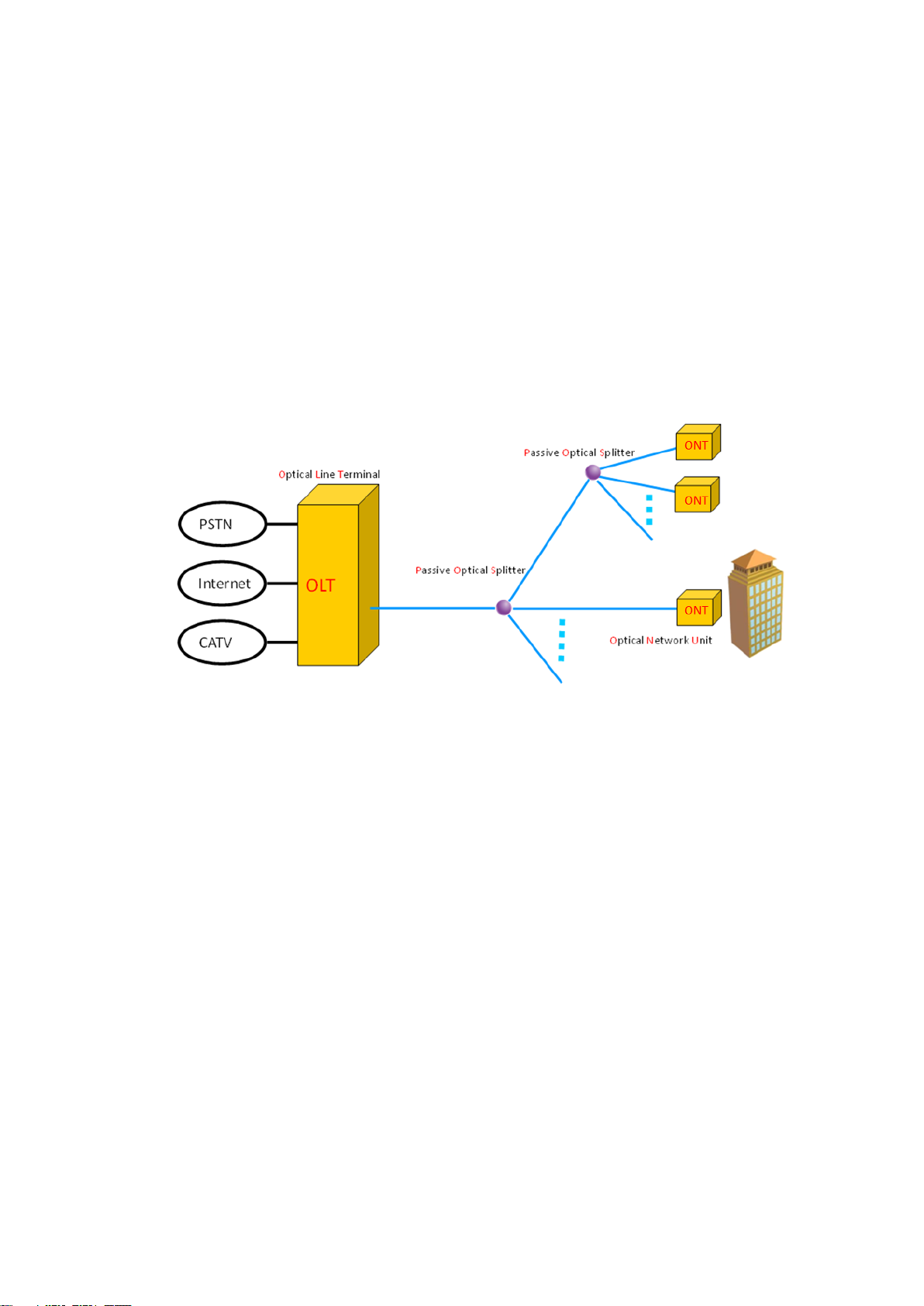
TP-Link presents the industry's leading GPON solution of P1200-08, which complies with the
relevant standards of ITU G.984.x and FSAN. P1200-08 is 1U Rack mount equipment, 8pon
ports, 8 GE uplink optic ports, 8 GE uplink electric ports. The maximum optical coupling ratio
of 1:128, up to 1024 GPON ONTs. The down link band width is 2.5Gbps and uplink bandwidth
is 1.25Gbps. The product is in compact design and convenient for flexible using, easy to
deploy with high performance. It can meet the requirements of equipment performance and
compact volume of the room environment. It can also satisfy the requirements of the access
network and enterprise network that enhancing the network function, improving the reliability
and reducing power consumption. The product is suitable for the "triple play" service, the
resident of optical access network, video surveillance network, enterprise network and the
Internet of the network applications.
Figure 1-1 P1200-08 in GPON system
1.2 Functional Features
Comply with ITU-T G.984/G.988 standards and China's Telecom industry GPON
standards.
Support OMCI remote management of ONT/ONT, compatible with ITU-984.4 OMCI
protocol.
Standalone 1U 8PON compact design of OLT products
P1200-08 provides 8 GPON ports, 8 uplink GE optical ports + 8 uplink GE electric ports, 10
Gigabit card expansion slot provides 2*10Gigabit SFP+ uplink port. Each PON port supports
128 ONT, total 1024 ONT for one chassis. Support dual power supply redundancy, 220VAC
and -48VDC mixed.
The complete layer 2 switching function
OLT is with powerful layer 2 switching capacity and complete layer 2 protocol. Supporting with
the exchange, isolation and One By One working mode. Supporting port aggregation, VLAN,
port speed, queue technology, flow control technology and ACL rich two layer function.
Offering the technical support for the development of the multi-service fusion.
The QOS security
GPON products is with complete DBA function and excellent ability of QoS service. DBA
provides a variety of QoS for the GPON system by means of four types of bandwidth and five
1

Item
Specification
Chassis
Slots
1*10 Gigabit uplink card slot
2 power module slot
Uplink Port
Copper
8*10/100/1000M auto-negotiable
SFP
8 SFP slots(1000BASE-TX interface)
10 Gigabit card
2 SFP (optional)
PON Port
QTY
8
Physical Interface
SFP Slots
Connector Type
ITU-TG.984.2Class B+ or ITU-TG.984.2Class C+
Max splitting ratio
1:128
Management Ports
1 MGMT port
Reset
Reset OLT equipment
LED
Status
Indication
PWR n (n = 1/2)
Green ,Always ON
Normal Power supply
OFF
Power supply is unconnected or
breaks down
types of T-CONT. It can meet different business flow of time delay, jitter and packet loss rate
of different QoS requirements.
Easy-to-use management system
Support CLI management. complying with OMCI standard. Realizing the business
management through OMCI channel protocol, including the ONT function parameters, type
and number of T-CONT business, QoS parameter, configuration request information and
performance statistics, automatic notification running event system, the realization of OLT on
ONT configuration, fault diagnosis, performance and security management.
1.3 Appearance and Interface
The P1200-08 1U high Pizza-Box, can be mounted into the standard 19” rack. Demission of
machine frame: 440mm (L)*391mm (W)*44mm (H).
As shown below:
Figure 1-2 Front View of P1200-08
See the following table:
Please refer to Table about LED and button on the front panel of OLT.
2

SYS
Flash per second
System normally operate
MGMT
Green , Always ON
Management port is connected
OFF
Management port isn't connected
S_PRS
Green , Always ON
10 Gigabit Uplink Card installed
OFF
10 Gigabit Uplink Card uninstalled
P n ( n=1/2/3/4/5/6/7/8)
Flash
There is communication data at
GPON port(n)
Green , Always ON
There are ONT register on OLT
port(n) and the optical fiber link is
normal.
OFF
NO ONT link with the OLT port(n)
GE n ( n=1/2/3/4/5/6/7/8/9/
10/11/12/13/14/15/16)
Flash
There is the communication data at
the uplink port(n)
Green , Always ON
The uplink port(n) is connected
OFF
The uplink port(n) isn't connected
ALARM
Always ON
One fan doesn’t work
Slow Flash
Two fan doesn’t work
Fast Flash
More than three fan doesn’t work
OFF
All the fan work
Item
Specification
Grounding Terminal
One, it's in the left of the front panel and is used to grounding for machine
frame
10 Gigabit Uplink Card
Support Pluggable type 10 Gigabit uplink card, two 10 Gigabit uplink port,
Figure 1-3 Back View of P1200-08
3

optional
Power module
Support Pluggable type two power module. You can chose AC or DC power
supply, optional
2 Pre-Installation Preparation
2.1 Power Requirement
The input voltage must be stable, no EMI noise and distortion.
When use DC power supply, the input voltage is -48VDC, the allowed range is -36 ~ -72 VDC.
When use AC power supply, the input voltage is 110/220VAC, the allowed range is 90 ~ 264VAC.
Note: Follow all security specification and the rule about the electricity in the locality or the
building. All power supply must be legal.
2.2 Equipment Ground
The grounding body must be configured in the machine room, the grounding resistance value is
less than 1Ω. It can be realize by layout the anti-static copper nose.
2.3 Room Design Requirements
The environment of the equipment operation has very big effect on its long-term reliable
operation .Room design requests to up to the following standards:
The device allows room temperature is 0 ° C ~ 40 ° C. To ensure that equipment works in the
normal temperature environment (25 ° C or so), should try to make the equipment away from
the main heat source (such as power supply, etc.), if the environment temperature is higher
than 40 ° C, should try to improve the ventilated condition of the room, such as install fan in
the frame or air conditioning in the room. The ventilation pipe in the room should be swept
clean and ventilated, etc.;
There must be the good cable wiring and go line space in the room. Cable and optical cable
wiring (including fiber splicing work) are already in place.
The related humidity 10%~95%, No condensation, no frost;
The dust particles density with more than 5μm in diameter≤3.0*104/m3 ; Dust particles is a
non-conductive, the non-magnetic and the non-corrosive.
3 Hardware Installation
3.1 Open package and checkout
According to the packing list or supply contract, check and verify the goods, if any component is
loss, wrong or damaged, please contact with your customer manager.
The list includes the following content normally:
1 OLT Machine(1 Pcs)
SFP modules are ordered according to user requirement
4

AC power line or DC power line according to user requirement
RJ-45-to-DB-9 console cable
3.2 Pre-installation Preparation
Verify the following working environment and installation requirements
1. Power Supply Requirement:
- DC power supply: –48V DC, the allowed range:-36VDC~ -72 VDC
- AC power supply: 110/220V AC, the allowed range: 90 ~ 264VAC
2. The equipment should be equipped in the dry, cool place, at least have 10 centimeters at both
sides for the ventilation space.
3. Avoid the direct light, far away from the heat source or the place with the stronger
electromagnetic interference
4. If want to install OLT inside the rack, ensure that have the necessary mounting screws and
nuts and necessary tools.
5. Check the required cable and connectors for installation
6. In the system management, need connect the following equipment with OLT:
- A management platform, such as PC
- RJ45/DB9 RS232 Console line
3.3 OLT Installation
OLT can be put in the bigger horizontal surface or within the standard EIA 19" rack.
3.3.1 Plane stack installation
Step I: Pre-Installation Validation
Ensure the worktable is strong enough to support the weight of the device and cables.
Ensure no obstacles on the worktable and the surroundings affecting the installation of the
device exist.
Prepare the OLT device to be installed and move the device to the place where is near the
work table and facilitates the handling.
Step II: Lift the OLT device and slowly move to the front of the worktable.
Step III: Move the OLT device to the location slightly higher than the worktable and then place the
OLT device to the specified location on the worktable.
3.3.2 Rack Installation
OLT equipment can be installed inside 19’’ rack which is compliance with ETSI standard. OLT rack
diagram as shown in below.
5

Front Panel
Figure 3-1 Rack installation
The installation process is as follows:
Step I: Pre-Installation Validation
Ensure the cabinet is fixed and the installation location of the OLT device in the cabinet is well
arranged, and no obstacles inside the cabinet and the surroundings affecting the installation
of the device exist.
Prepare the OLT device to be installed and move the device to the place where is near the
cabinet and facilitates the handling.
Step II: Lift the OLT device and slowly move the device to the front of the cabinet.
Step III: Lift the OLT device to the location slightly higher than the tray or sideway of the cabinet,
place the OLT device to the tray or sideway of the cabinet and then push it to the cabinet.
Step IV. Use screws to fix the suspension loops of the cabinet to the square holes of the 19-inch
cabinet column and to fix the OLT device to the cabinet.
3.4 Port and Connection
The chapter describes the port and power supply connection situation in OLT system, mainly
include the following parts:
Uplink Port
PON Port Connection
Ground Cable Connection
Management Port Connection
Please carefully read the following introduction before connecting each port of OLT:
3.4.1 Uplink Port
3.4.1.1 Port Explanation
OLT offers eight GE electrical port, eight GE SFP optical port and two 10 Gigabit port for uplink.
Electrical port and optical port can combination at the sometime, you can use direct-through, cross
cable or fiber connection of the OLT and uplink equipment.
SFP module can be the optical module or the electrical module, and follow standards below:
1000Base-LX (Long wave length)
1000Base-SX (Short wave length)
6

10/100/1000Base-TX (Electrical port)
When use the single mode optical fiber, the maximum transmission distance can be up to 10-40km;
when use the multimode fiber, the maximum transmission distance is less than 500 meters.
Gigabit Ethernet uplink port supports the duplex mode and flow control auto negotiation.
But need note that the maximum length of the optical fiber is related with work mode of the optical
fiber:
Maximum length of 1000Base-LX fiber is depend on duplex mode.
Maximum length of 1000Base-SX fiber is the same in both full duplex and half duplex mode.
3.4.1.2 Port Connection
There are two kinds of uplink network connection:
Cable with RJ45 connectors at both sides
Cable with LC connector at both sides
Decide the port type of OLT according to the port type of the uplink device (Switch or Route).
3.4.1.3 Method of making cable
If you use SFP optical module, cable specification: the optical cable with LC connector at both
sides.
If you use GE copper interface, cable specification: Category 5 cable or Category5 super cable
with RJ45 connector at both sides45.
The below the reference for making STP (Shielded Twisted-Pair) cable with RJ45connector at
both sides.
3.4.2 PON Port Connection
P1200-08 support eight GPON SFP slots, every SFP GPON slots can mount a GPON SFP
module and provides one PON port.
Caution: When insert into optical cable, please confirm the connector is inserted into the
correct position, thus guarantee the good contract.
7

Port on Computer
Cable Required
Port on OLT
Serial Port
RJ-45 to DB-9 Console Cable
RJ-45 Console Port
USB Type-A Port
USB to RS-232 compatible
serial port adapter ( Adapter
may require a software driver )
RJ-45 to DB-9 Console Cable
SFP PON slots installs standard ITU-TG.984.2Class B+ or ITU-TG.984.2Class C+OLT SFP .The
OLT SFP interface is SC/PC. Please use the patch cord with SC/PC connector to connect
between the OLT and the ODN networking.
3.4.3 Ground Cable Connection
Ensure the safety and reliable working of OLT. P1200-08 should be connected with the ground if
necessary. Grounding screws are located in the rear panel. While connecting, you should use
screwdriver to loosen the grounding screw first, then connect the ground cable, finally tighten the
screws.
3.4.4 Management Port Connection
P1200-08 equipment provides console interface (marked as “CONSOLE” RJ45 type port) and
MGMT management internet access (marked as “MGMT” RJ45 type port).
Console access is really only required when initially configuring a device, or if remote access fails.
Console access requires:
Console cable: RJ-45-to-DB-9 console cable
Terminal emulation software: HyperTerminal
The cable is connected between the serial port of the host and the console port on the device.
Most computers and notebooks no longer include built-in serial ports. If the host does not have a
serial port, the USB port can be used to establish a console connection. A special USB-to-RS-232
compatible serial port adapter is required when using the USB port.
Figure 3-1 Connecting the Console Port
8

When starting the management, please use straight and cross Ethernet cable, connecting
“Console” management interface to network or managed PC.
MGMT access requires:
RJ45 cable
Terminal emulation software: HyperTerminal
3.4.5 Power Supply
3.4.5.1 Connecting the AC Power Cable
The two AC power supply units in the P1200-08 allow for 1 + 1 power redundancy. If one power
supply unit fails, then the system will continue to operate using the remaining power supply unit.
Additionally, to ensure true AC line input redundancy for the OLT, you should connect each AC
power cable to a different AC power source. You can also connect an uninterruptible power supply
(UPS) between each AC power source and the OLT to increase the availability of the OLT.
1. Get the supplied AC power cords from the OLT's shipment kit.
2. Connect one end of each AC power cord into the AC power inlet connectors located at the rear
of the OLT.
3. Connect the other ends of the power cords into AC wall outlets. Connect each AC power cord
to a different AC power source if you want AC line input power redundancy.
Figure 3-2 Connecting to Power Supply
9

3.4.5.2 Connecting the DC Input Power Cable
1. Identify the parts that you will use to assemble the DC input power cable
The following DC connection cable is required to assemble one or more DC power input cables.
These cables connect the -48V DC input source(s) to the power supply units.
2. Turn off power from the DC power source through the circuit breakers.
Caution - Do not proceed with these instructions until you have turned off the power from the DC
power source through the circuit breakers.
3. Get a DC input plug from the ship kit.
4. Locate the four wires coming from the DC power source that will be used in the connection to
your unit:
-48V: negative terminal
-48V: Return (positive terminal)
-48V: Earth ground
5. Unscrew the screws, the cable wire fixed on the DC screw.
6. Repeat Step 5 for the other two wires to complete the assembly of the DC input power cable.
3.5 OLT working status checkout
3.5.1 Check out power supply
Before you connect the power supply, double check the power supply if it is accord with the power
supply requirements, If each module and card are installed correctly, If the equipment is in reliable
grounding or not. After checking everything is OK, you can turn on the power supply sources.
3.5.2 Check out OLT’s working status
Please check if the OLT’s working status from following aspects:
Check the power LED. The power LED will be on.
The SYS LED will flash per second.
If the uplink equipment is connected to the uplink port, the relevant connection LED is on.
3.5.3 Network Management Checkout
Local Command Line Interface Management:
Use the RJ45/DB9 Serial Port cable (in package) to link management PC with P1200-08
CONSOLE or MGMT port. Management computer can access to OLT equipment from Super
terminal interface of the PC for configuration.
※Please refer to relevant CLI user manual.
4 Default Configuration
4.1 Network Parameter Configuration
Management Port
10

Item
Specification
Chassis
Rack
1U 19 inch standard box
Slots
1*10 Gigabit uplink card slot
2 power module slot
Uplink Port
Copper
8*10/100/1000M auto-negotiable
SFP
8 SFP slots(1000BASE-TX interface)
10 Gigabit card
2 SFP (optional)
PON Port
QTY
8
Physical Interface
SFP Slots
Connector Type
ITU-TG.984.2Class B+ or ITU-TG.984.2Class C+
Max splitting ratio
1:128
Management Ports
1 MGMT port
1CONSOLE port
IP Address: 192.168.1.100
Subnet Mask: 255.255.255.0
Default Gateway: 192.168.1.1
4.2 CONSOLE Parameter Configuration
Band Rate: 9600
Data Bit: 8
Parity Check: NO
Stop Bit: 1
Flow Control: NO
4.3 Default Username and Password
Local Command Line
Username: root
Password: admin
5 Appendix: OLT Specification
11

PON Port Specification
(Apply to C-Data PON module)
Transmission Distance :20KM, PON port speed:
Downstream Data Rate: 2.5Gbps, Upstream Data
Rate: 1.25Gbps, Wavelength: 1490nm
TX,1310nm RX, Connector: SC,
Fiber Type: 9/125μm SMF, TX Power: +1.5 ~
+5dBm,
Rx Sensitivity: -28dBm, Saturation Optical Power:
-8dBm
Management Mode
CLI
Management Function
Support for state monitoring, configuration
management, equipment log, equipment
upgrades, equipment management, user
management.Layer-2 switch configuration such
as Vlan, Trunk, RSTP, IGMP, QOS, etc. PON
management function: DBA, ONT authorization,
ACL, QOS, etc. Online ONT configuration and
management. User management. Alarm
management
Dimension
440mm(L)*391mm(W)*44mm(H)
Weight
4kg
Power
Supply
220VAC
AC: 90V~240V,47/63Hz
-48DC
DC:-36V~-72V
Power Consumption
65W
Operating
Environment
Working Temperature
0~50℃
Storage Temperature
-40~85℃
Relative Humidity
5~90%(non condensing)
12
 Loading...