

Page 1

Version: V1.0
EMS User Guide
GPON OLT P1200-08
Page 2

COPYRIGHT & TRADEMARKS
Specifications are subject to change without notice. is a registered trademark of
TP-Link Technologies Co., Ltd. Other brands and product names are trademarks or registered
trademarks of their respective holders.
No part of the specifications may be reproduced in any form or by any means or used to make any
derivative such as translation, transformation, or adaptation without permission from TP-Link
Technologies Co., Ltd. Copyright © 2017 TP-Link Technologies Co., Ltd. All rights reserved.
http://www.tp-link.com
I
Page 3

About This Manual
This manual is applicable to TP-Link GPON OLT products, The contents of this document
include TP-Link PON Element Management System (hereinafter refer to as “EMS”) software
installation and operation guidelines. Users should learn this document first when beginning to
operate GPON OLT device.
II
Page 4

CONTENTS
1 Software Introduction .................................................................................................................. 1
1.1 Software Information ...................................................................................................... 1
1.2 Functional Features ....................................................................................................... 1
2 EMS Software Installation ........................................................................................................... 1
3 EMS Start-Up ............................................................................................................................... 2
3.1 EMS Server Start-Up ...................................................................................................... 2
3.2 EMS Client Start-Up ....................................................................................................... 2
3.3 Login EMS ...................................................................................................................... 2
4 EMS Software Framework Introduction ...................................................................................... 3
4.1 Main Window Introduction .............................................................................................. 3
4.2 Device Management Window ........................................................................................ 5
5 Add and Delete Management Object .......................................................................................... 5
5.1 Add and Delete Location ................................................................................................ 5
5.2 Add and Delete Device .................................................................................................. 7
6 GPON OLT Management ............................................................................................................ 9
6.1 OLT Chassis Management ............................................................................................. 9
6.2 OLT Chassis Management ........................................................................................... 10
6.2.1 View System Status ............................................................................................ 11
6.2.2 OLT Management Configuration ....................................................................... 12
6.2.3 OLT and ONU Upgrade Management .............................................................. 14
6.2.4 OLT Uplink Port Attribute Configuration ............................................................ 15
6.2.5 OLT trunk(LACP) Configuration ........................................................................ 16
6.2.6 OLT Port Mirror Configuration ........................................................................... 18
6.2.7 OLT Mac Address Management ........................................................................ 20
6.2.8 Uplink Port Broadcast Storm Suppression Configuration ................................. 22
6.2.9 OLT Port VLAN Management ........................................................................... 24
6.2.10 OLT STP Management ...................................................................................... 40
6.2.11 ACL Management ............................................................................................. 44
6.2.12 OLT QoS Configuration ..................................................................................... 51
6.3 OLT PON Card Management ....................................................................................... 54
6.3.1 OLT PON Port Basic Configuration ................................................................... 55
6.3.2 View OLT PON Port Optical Module Information .............................................. 56
6.3.3 OLT DBA Profile Configuration .......................................................................... 56
III
Page 5

6.3.4 OLT line Profile Configuration ........................................................................... 59
6.3.5 OLT Service (business) Profile Configuration ................................................... 65
6.3.6 OLT Traffic Profile Configuration ....................................................................... 76
6.3.7 PON Radio Storm Suppression ........................................................................ 77
6.3.8 ONU Auto Authentication .................................................................................. 79
6.3.9 ONU VOIP Service Configuration ..................................................................... 85
6.3.10 Upgrade ONU .................................................................................................... 95
6.4 PON Port Is Managed Separately ................................................................................ 97
7 Manage ONU Device ................................................................................................................ 98
7.1 Introduction of ONU Management ............................................................................... 98
7.2 ONU Basic Information Management .......................................................................... 99
7.2.1 View Basic Information of ONU ......................................................................... 99
7.2.2 ONU Capability Set Information View ............................................................... 99
7.2.3 ONU Optical Link Information ......................................................................... 100
7.3 ONU Port Management .............................................................................................. 101
7.3.1 Basic Configuration of ONU Port .................................................................... 101
7.3.2 ONU Port Access Mode Vlan Configuration ................................................... 101
7.3.3 ONU Port Rate Limit........................................................................................ 102
7.4 ONU CATV Management ........................................................................................... 103
7.5 ONU VOIP Service Configuration .............................................................................. 104
7.5.1 ONU VOIP Service IP Configuration ............................................................... 104
7.5.2 ONU VOIP Registered Tel-number Configuration .......................................... 106
7.5.3 View ONU VOIP Registered State .................................................................. 108
8 Operation Logs Management .................................................................................................. 109
9 Alarm Logs Management ......................................................................................................... 111
10 Database Management ............................................................................................................ 114
11 User Management .................................................................................................................... 115
12 Device Upgrade ........................................................................................................................ 116
13 Device Search Function ........................................................................................................... 118
14 End ........................................................................................................................................... 119
IV
Page 6

1 Software Introduction
1.1 Software Information
The EMS software is a C/S architecture integrated device management platform, which is
designed based on SNMP protocol.
The EMS need following operational environment:
OS: Windows XP/2000/Vista/7/8/10
Hardware: at least 2.4GHz CPU, 512M memory
Software: JAVA 1.5, MySQL 5.0
1.2 Functional Features
The EMS software has following main features:
Based on standard SNMP protocol
Support multi-user access, C/S structure
Support centralization management of TP-Link GPON serial products
Support discovering topology automatically, TreeView, modifying topology manually
Support all functional configuration
Support division of management rights
Support real-time alarm and historic alarm log query
Support perfect log management
Use single database and Support database backup and import functions
Support real-time performance collection and port traffic statistics.
Use third-party open database platform
2 The EMS Software Installation
The EMS install file has integrated the database software by default, so as long as the EMS is
installed, the corresponding database software is also installed simultaneously. if your computer
has installed the database software already, you don’t need to uninstall it, it will not disturb the
EMS software installation.
It’s easy to install the EMS, just need to click ‘Next Step’, and you will finish it.
When you finish the installation of the EMS, you will find two Shortcuts in the installation directory
or desktop for server and
1
Page 7
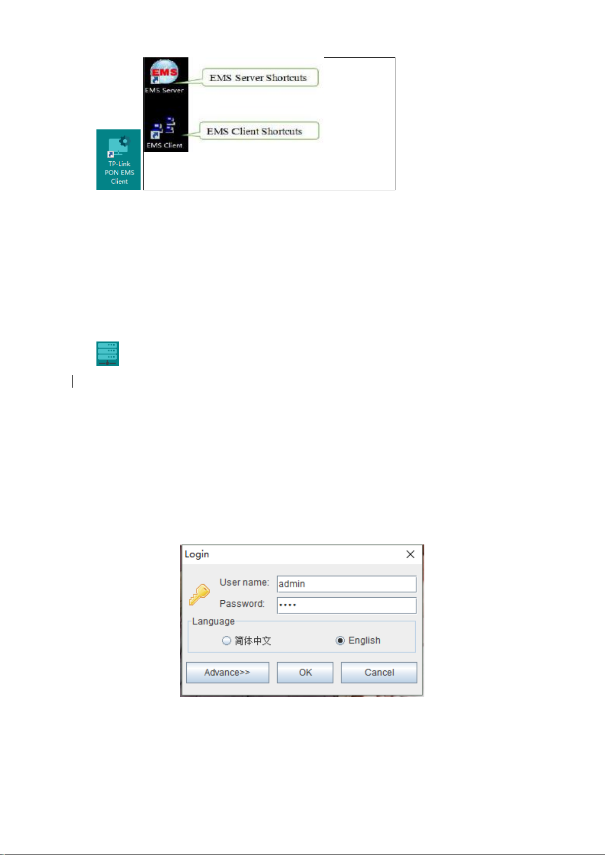
client .
Note: When the EMS installation finished successfully, you can start it directly.
3 The EMS Start-Up
The architecture of EMS is C/S (Server and Client), Server and Client. You should start Server
program before start Client program.
3.1 EMS Server Start-Up
Run the TP-Link PON EMS Server (hereinafter refer to as “EMS Server”) program, we will find
icon in the system tray after the Server runs successfully
Note: EMS Server start-up time is no longer than 30 seconds. If the program runs more than 30
seconds, it means the program doesn’t start properly.
3.2 EMS Client Start-Up
Run the TP-Link PON EMS Client (hereinafter refer to as “EMS Client”) program after the EMS
Server program starts. The EMS Client and EMS Server can be run on the same computer or two
independent computers with reliable intercommunication.
Note: To ensure operational performance of software, it is recommended that the EMS Server and
EMS Client be installed on the same computer or different computers in the same LAN.
After the EMS Client starts successfully, the login page will appears as follows:
3.3 Login EMS
If the EMS Server and EMS Client are installed on the same computer, enter the user name and
password and login directly. If the Server and Client are installed on different computers, you must
click the ‘Advance’ and configure, page appears as follows:
2
Page 8
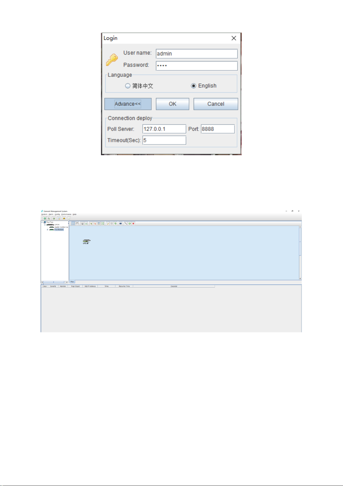
Configurations are as follows: change poll server’s IP to the server’s IP which EMS server runs on,
port and Timeout Keep the default.
Note: The default user is "admin", password is "1234"for client to login.
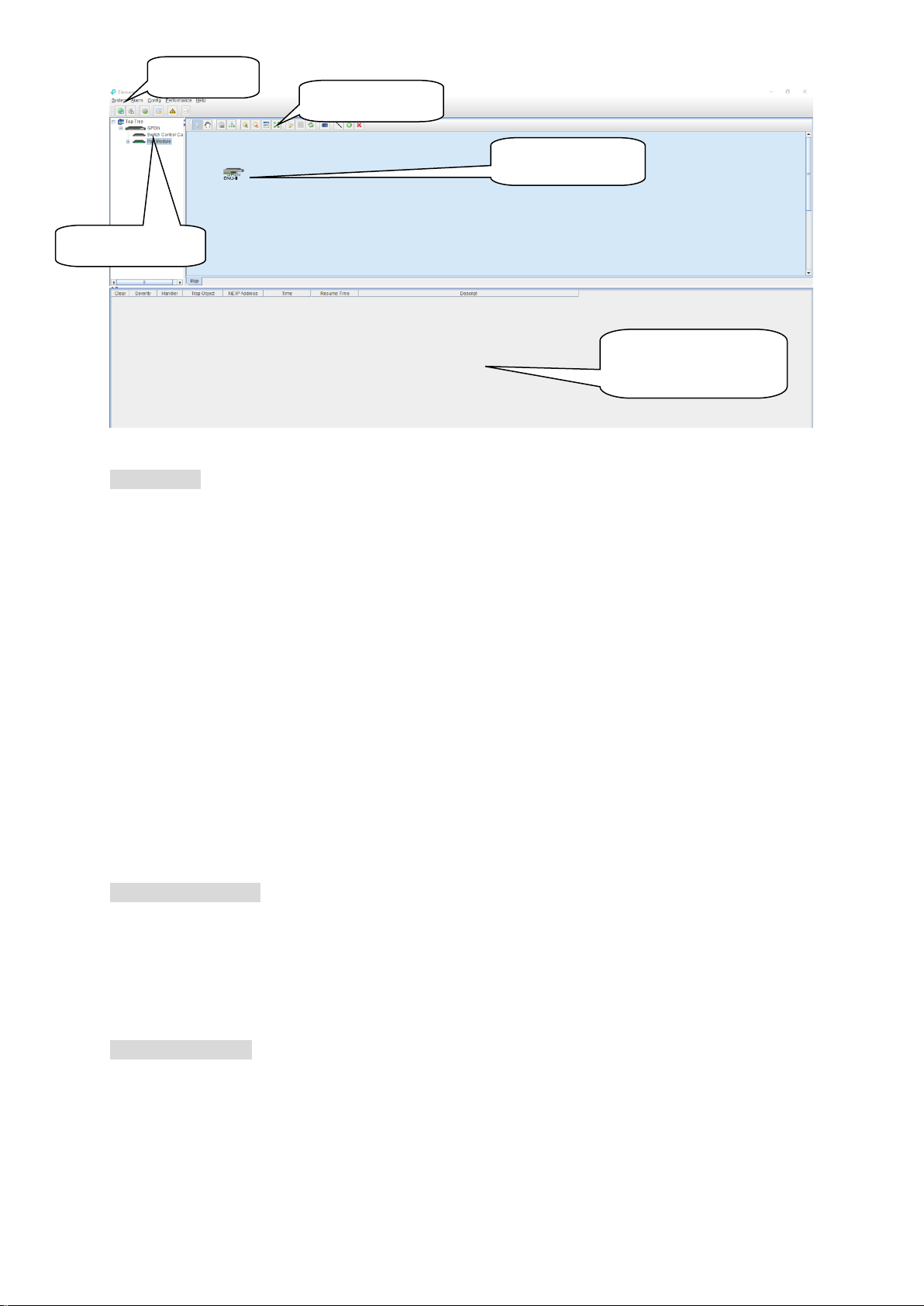
After login the EMS Client successfully, you will see the main page. The typical page appears as
follows:
At this point, The EMS Server and EMS Client programs have been started successfully.
4 EMS Software Framework Introduction
4.1 Main Window Introduction
After login successfully, system will enter main window management page.
3
Page 9
main menu
topology tool bar
Device list window
Topology window
real-time alarm
operation log window
As shown above, the EMS Client main window is divided into the following sections:
Main menu:
Main menu contains System, Alarm, Configure, Performance and Help parts. Their main features
are as follows:
Main Menu
Including System Configuration, MIB Browser, Database Maintenance and User Manage, etc.
Alarm Menu
Alarm Query, Configure Trap Rule and System Log are within this menu.
Configuration Menu
Top-tree update, device add/delete, device configuration, map update and device upgrade
features are located in this menu.
Performance Menu
Including performance monitor and alarm threshold configuration.
Help menu
Change software skin, language and about information.
Device list window:
The device list window shows all the devices under management currently. The device list can
directly observe whether the device is online, whether there is an alarm. You can enter into the
management window of the device by double click the device.
The OLT device has 5 level management object in the device list window, the machine box,
exchange control module, PON module, PON port and ONU level.
Topology window:
Windows of topology is the main display area of the EMS software, according to the management
device, user can move device to right position on regional background map for visual management.
Double click the device object on the topology diagram, you can enter the device management
window to perform various operations on the device.
The administrator can add or modify the passive network part of the topology diagram manually,
4
Page 10
such as the optical splitters in PON network, to make the topology same to the actual network
layout.
Real-time alarm and Operational log:
The real-time alarm window shows the abnormal alarm information of the current management
device, such as alarm object, alarm time, alarm content, etc.
The operation log window records all the operations of the EMS, so it’s convenient to trace who
has operated it.
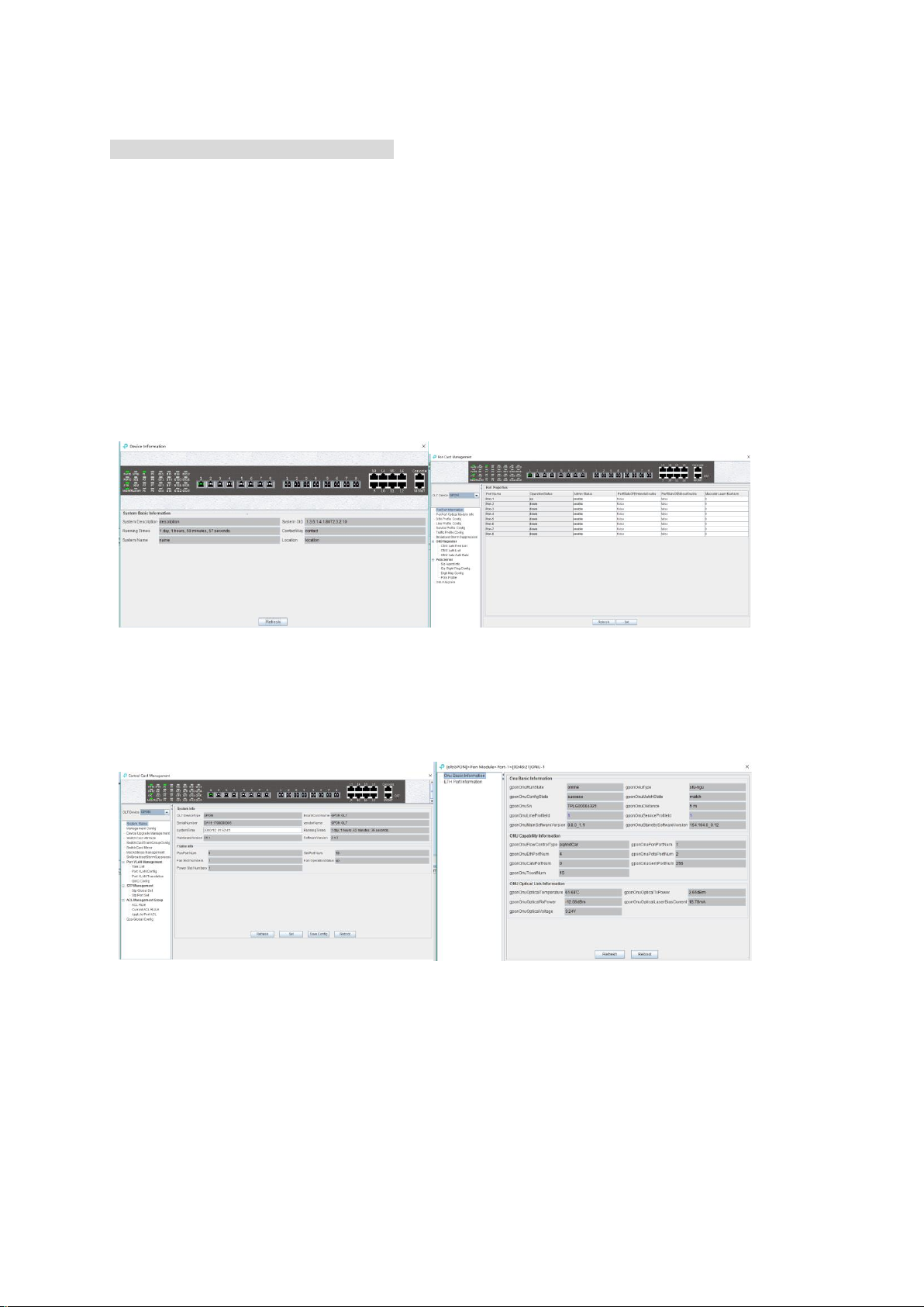
4.2 Device Management Window
For device management, EMS is mainly through the corresponding device management window
to operate. Through the Configuration menu or double click the device icons located on Top-tree or
topology map, manager can open the device management windows. Following are several typical
examples:
System Management Window PON Card Management
Switch and Control Card Window ONU management window
5 Add and Delete Management Object
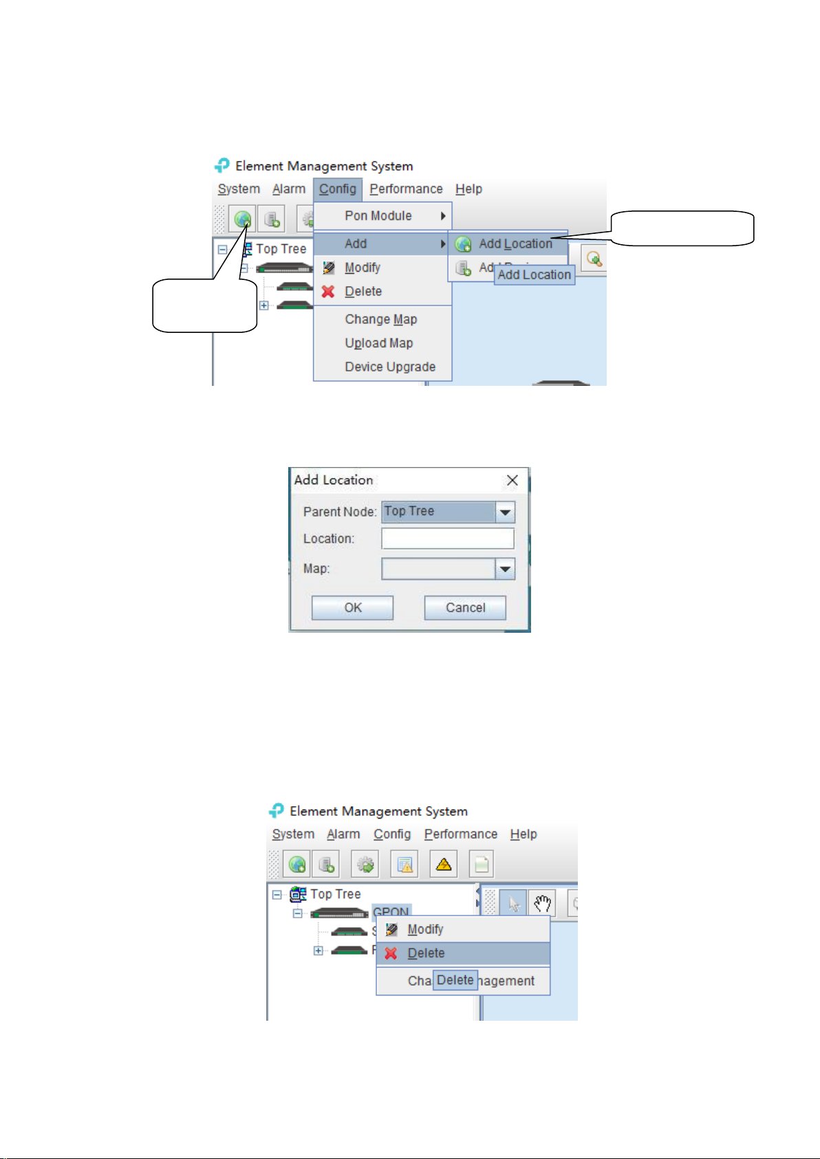
5.1 Add and Delete Location
For convenience of managing numerous devices, divide them in different regions according to
5
Page 11
Add Location
shortcut
Add Location menu
their deployed locations is normally needed. According to following steps to divide management
regions:
1) Add a Location node on the Top-tree list. Showing as follows:
As above figure, through ‘Add Location’ menu or its shortcut, open add location operate
window, as following:
Operation steps:
i. Select the parent node for new added node;
ii. Input the name of new node;
iii. Select map for the new location node (The map should be upload first), when select this
node on top-tree, the topology area will apply this map;
2) Location node delete
As above figure, right click the selected location node and delete it.
6
Page 12
Add Device shortcut
Add Device menu
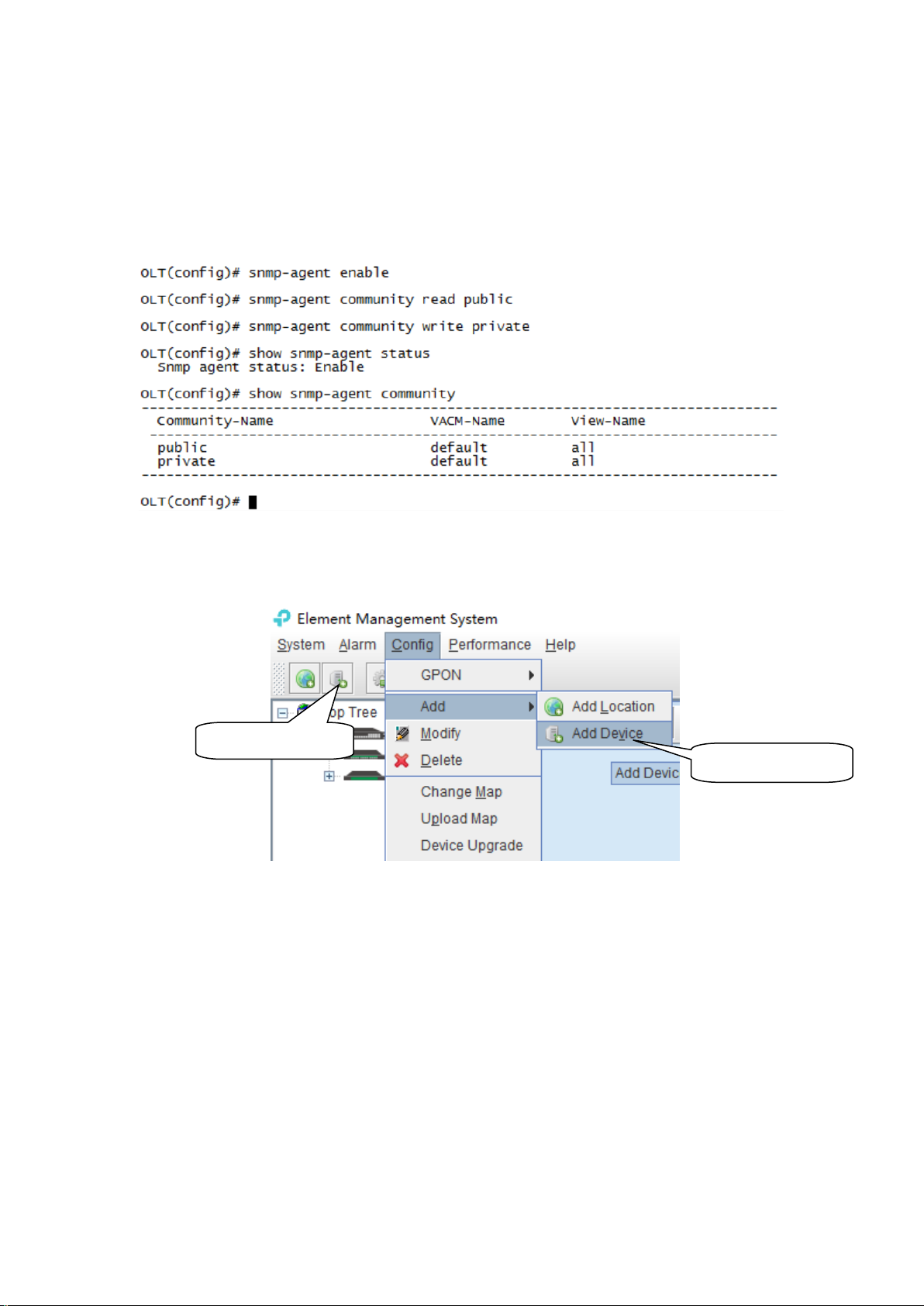
5.2 Add and Delete Device
Note: Before using EMS to manage an EPON device, you need to login OLT system to enable
SNMP functions and to configure the read-write community. The read the community is public, and
write community is private by default.
Configuration and view commands are as follows: (see CLI user Manual for more relevant
configuration view commands).
Next, you need to add the device to the EMS manually, and the operation of adding a GPON OLT
device is as follows.
1) Add OLT
As above figure, through ‘Add Device’ sub-menu or its shortcut to open the device add window
and add device.
7
Page 13
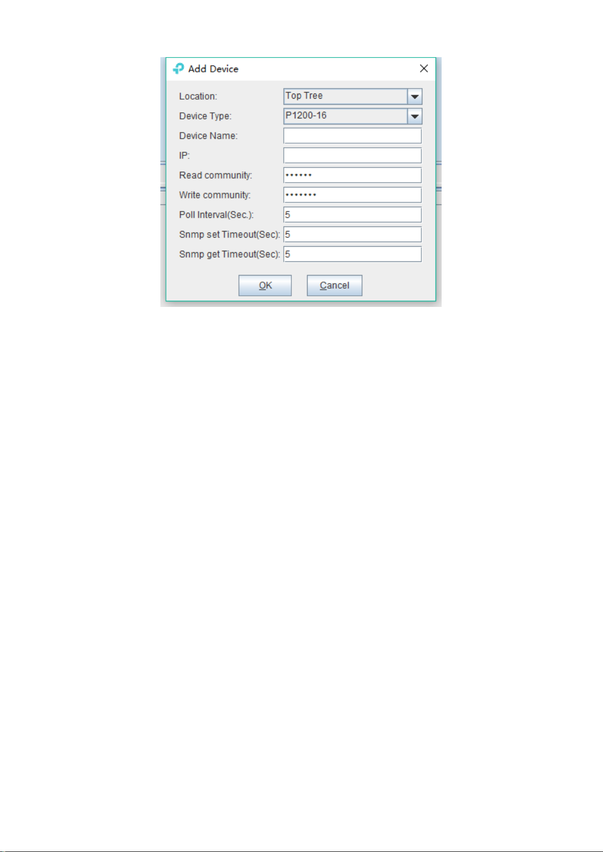
As above figure, the new added device need configure following parameters:
Location
Select the location node where the added device should be located.
Device Type
Select the device type for the new added device. The EMS can manage all TP-Link GPON OLT
products. So, it is needed to select correct device type. Select P1200-08 for TP-Link 8-port GPON
OLT device.
Device Alias
In order to recognize the managed device easily, a suitable alias is normally needed instead of IP
Address or MAC Address. This device alias will be displayed in the device list area.
IP Address
Input the management IP Address of the new added element device, which can be in-band or
out-band IP Address.
Read and Write Community
EMS software is designed based on SNMP protocol to communicate with managed devices. Read
and write community is used by SNMP protocol as access password. Community value inputted
here should be the same with which configured in managed device, such EMS can communicate
with the managed device successfully.
Polling Interval and SNMP Read and Write Timeout Value
EMS software will poll the managed device periodically with a configured time interval. Normally,
the poll interval can use the default value. SNMP read and write timeout values are the longest
wait time for EMS to wait response from managed device. Usually, the default value is suitable.
Manager can also revise these values according to the real network performance situation.
When the above parameters are configured, click OK button to finish the device add operation.
When success, the new added device’s icon will appear in the device list and topology area.
Showing as following figure:
8
Page 14
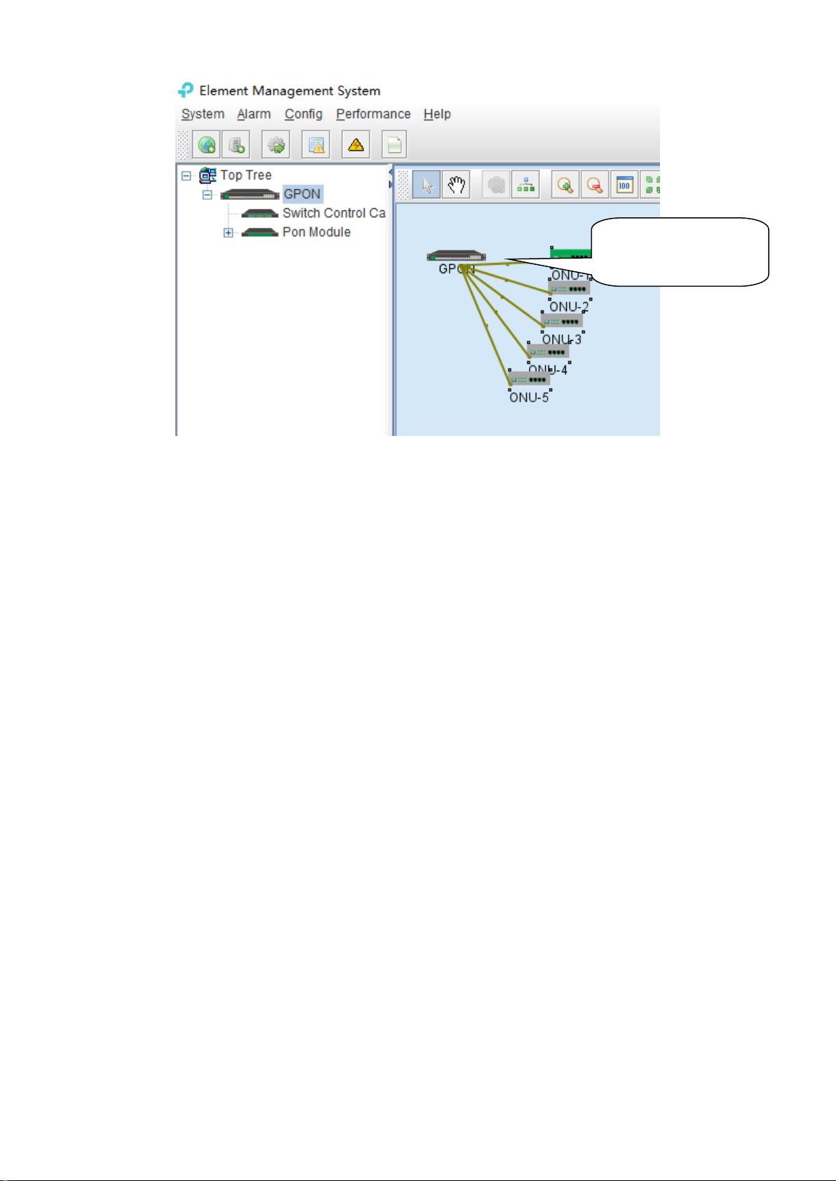
2) Delete OLT
Newly added device icon
on the topology diagram
Obsolete or unwanted device in device list can be deleted from EMS. Right click on the selected
device icon and select Delete option to delete a device.
Note:
i. Deleted device can’t be restored and need to be added when need.
ii. All the information of the deleted device will also be removed from EMS.
iii. None any configurations on the deleted device itself will be changed.
6 GPON OLT Management
OLT device mainly consists of OLT chassis, Switch and Control module, PON Card module and
ONU Device management module. The following sections describe the management of EMS
software for these parts.
6.1 OLT Chassis Management
Double click the OLT chassis icon to open the chassis management window. Typically as following
figure:
9
Page 15
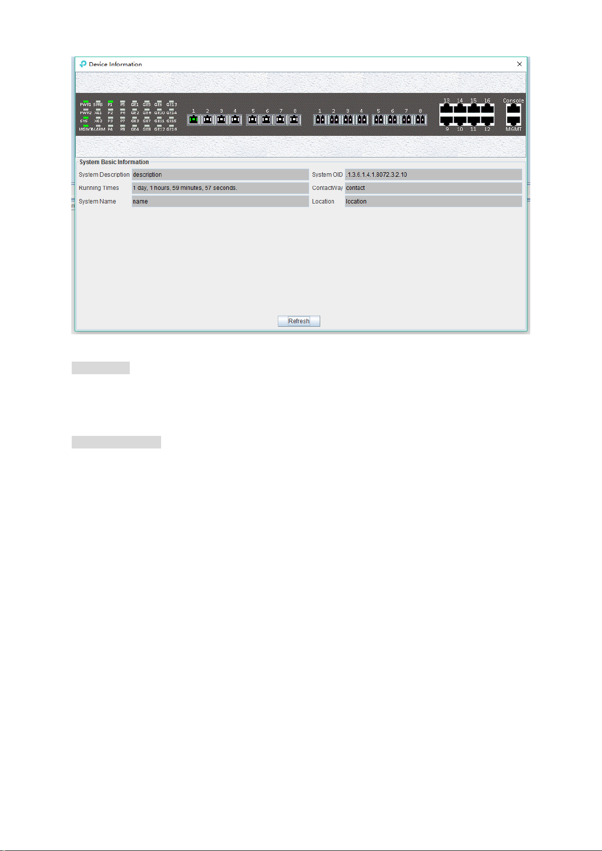
OLT chassis management includes following several parts.
Front Panel
The equipment panel parts display the power supply of the device and the status of each port
indicator light in real time. The meaning of the indicator is subject to the panel label.
When EMS can’t connect with the OLT this window will change to gray color.
Basic Information
This section shows the system description, system OID, running time, contact information, system
name, location and other basic information. Click ‘Refresh’ button can refresh the above
information.
6.2 Control Card Management
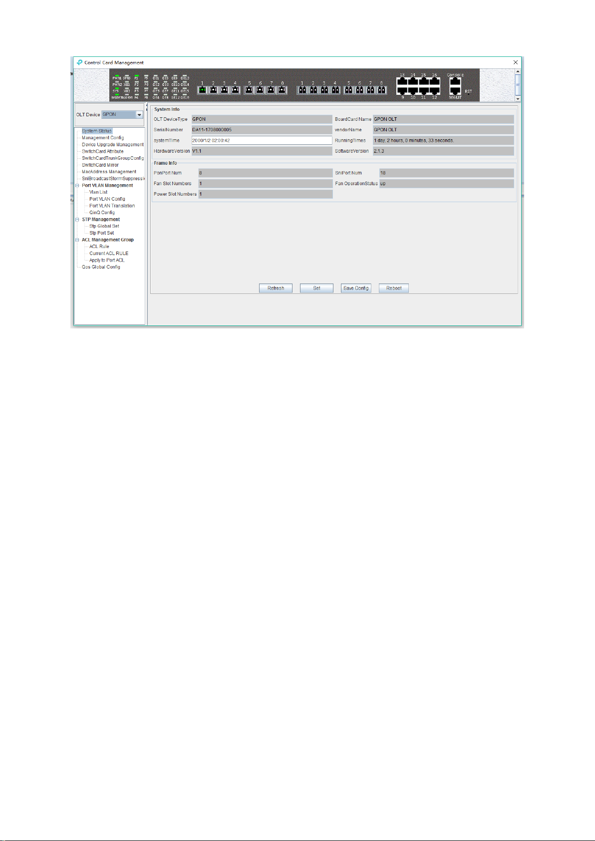
Double click 'Switch Control Card' icon in device list to open the 'Control Card Management'
window. Typical as following figure:
10
Page 16
Following management features are contained on this window:
view or set device basic information;
view or set the IP address, the trap address, SNMP management parameters, etc;
upgrade OLT device`s firmware;
view and set the uplink ports, such as the admin status of port, and the port rate;
Swap TRUNK functionality (link aggregation) configuration;
MAC address table management;
Uplink ports storm suppression management;
OLT port VLAN configuration management;
OLT IGMP configuration;
OLT STP configuration;
ACL management configuration;
QoS configuration;
Following sections in this part introduce the management features contained in the control card
management window.
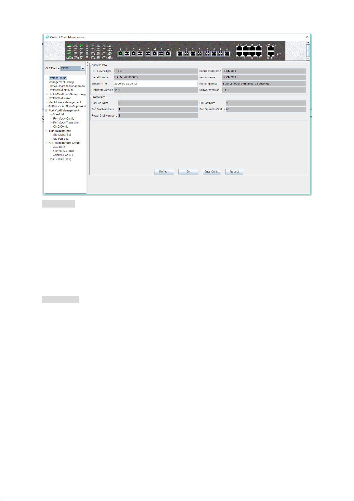
6.2.1 View System Status
Double click the 'Switch Control Card' icon on the left side of the main page to open the 'Control
Card Management' window and enter the 'System Status' to view the page.
11
Page 17
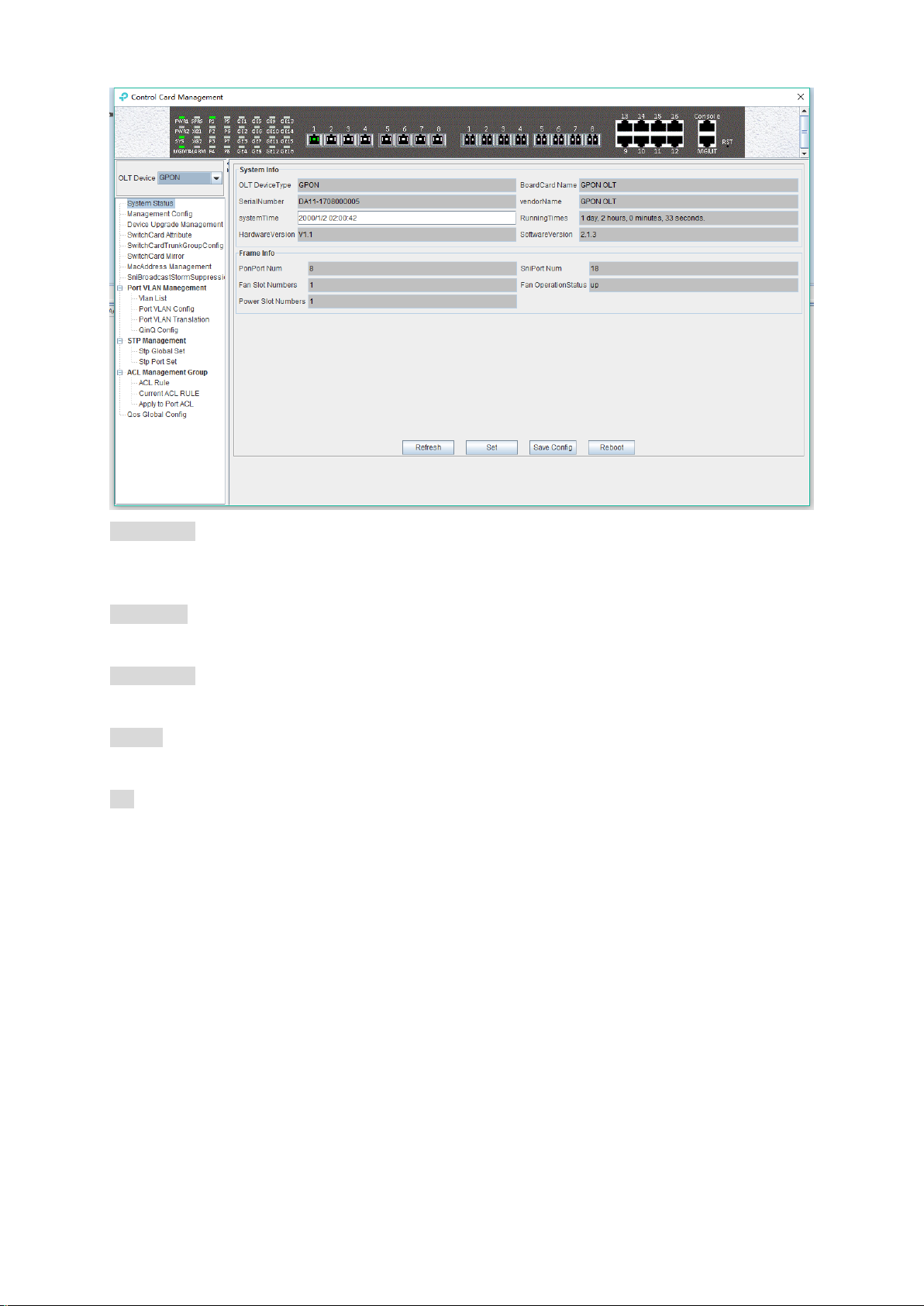
System info
Display Board card name, serial number, vendor Name, system time, software and hardware
version number, device running time and other information.
Frame info
Display PON port number, GE port number, fan slot numbers, and fan operation status.
Save config
The button of ‘Save Config’ is mainly for saving all configuration of OLT.
Reboot
Click ‘Reboot’ button, and OLT will reboot.
Set
The button of ‘Set’ is used for setting system time.
6.2.2 OLT Management Configuration
Double click the 'Switch Control Card' icon on the left side of the main page to open the 'Control
Card Management' window and enter the 'Management Config' page:
12
Page 18
System info
View inband IP address, outband IP address, subnet mask, gateway, inband VLAN.
Instructions:
1) Inband management comes from uplink port and needs to add management VLAN for uplink
port.
2) Outband management comes from MGMT port and needs to add IP for MGMT port.
3) Normally, modify the IP of management and device parameters, EMS will lose connection with
device, user need to modify management IP of device in EMS, only in this way, can we
connect device again.
Trap address
Alarm receiving address is the destination IP address which alarm information sent to, when the
alarm occur, GPON OLT will sent Data Packet of ‘SNMP TRAP’ to the management PC, usually,
trap address is same to the PC’s IP which start EMS, Users can set four trap addresses mostly.
[Example of trap address configuration]
Example: configure trap information as follows :host name is 1234,Alarm reception address is
192.168.5.135,The alarm port is 162,community is public.
13
Page 19

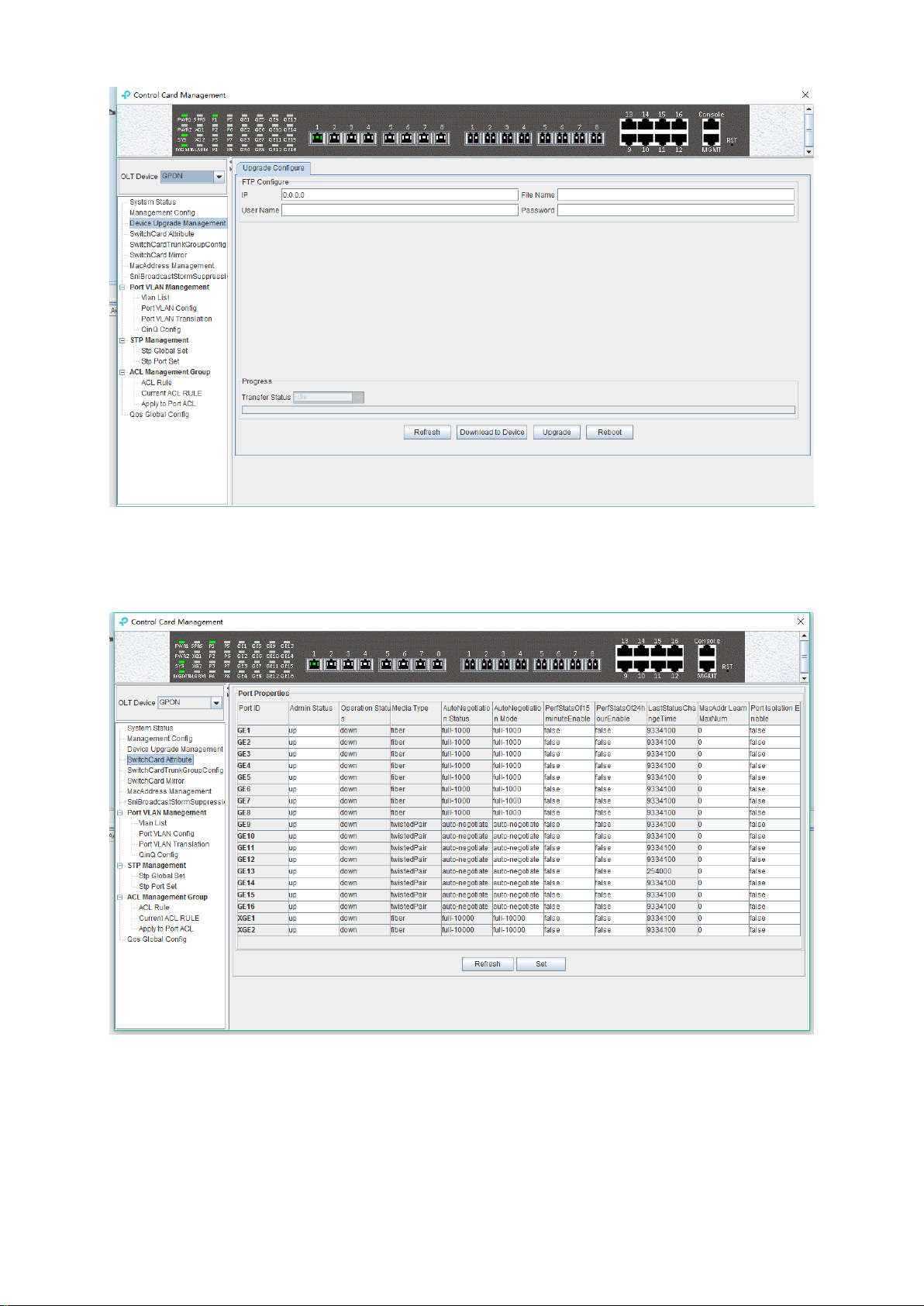
6.2.3 Device Upgrade Management
Double click the 'Switch Control Card' icon on the left side of the main page to open the 'Control
Card Management' window and enter the 'Device Upgrade Management' page.
The configuration management interface can upgrade the software of OLT.
Note: before upgrading, you need to ensure that there is an upgrade file. The FTP server need to
connect with OLT.
[Example of device upgrade configuration]
Example: Upgrade firmware via FTP server which IP is 192.168.5.153.
14
Page 20
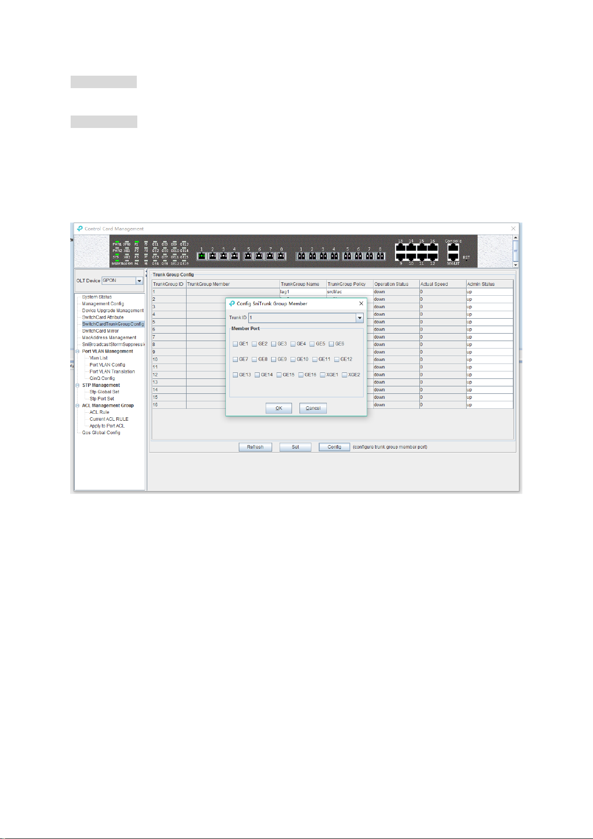
6.2.4 OLT Uplink Port Attribute Configuration
Double click the 'Switch Control Card' icon on the left side of the main page to open the 'Control
Card Management' window and enter the 'Switch Card Attribute' page.
The ‘Switch Card Attribute’ management page is mainly used to configure and view the attribute
parameters of OLT 's uplink port (GE photoelectric port and 10GE uplink port). The parameters are
described as follows:
Admin Status
Set the uplink port state to enable or disable. When the port is set to 'Up', the port is opened and
15
Page 21

when the port is set to 'Down', the port is closed, 'testing' status is not available currently.
Operation Status
Displays the current link state of the uplink port, when the uplink port connects with the end
devices, the operation state is displayed as 'Up '; when the uplink port does not connect with any
end devices, the operation state is displayed as 'Down ', and the running state only shows but
can’t be configured.
Media Type
Show the media type of the uplink port, the default interface of GE1-GE8 is the optical interface,
and the media type is shown as 'Fiber'. the default interface of GE9-GE16 is the electrical
interface, and the media type is shown as 'Twisted Pair '; XGE1 and XGE2 are uplink port of
10GE.
Auto Negotiation Status
Display the uplink port rate and duplex mode, 1000M full duplex, 100M full duplex, 10M full duplex
and auto negotiation status.
Auto Negotiation Mode
Configure the uplink port rate and duplex mode, 1000M full duplex, 100M full duplex, 10M full
duplex and auto negotiation mode.
PerfStats Of 15 minute Enable
Configure PerfStats Of 15 minute Enable of uplink port, ’False’ means stop performance statistics
of every fifteen minutes on uplink port. ’True’ means start performance statistics of Every fifteen
minutes on uplink port.
PerfStats Of 24 hour Enable
Configure PerfStats Of 24 hours Enable of uplink port, ‘False’ means stop performance statistics
of every 24 hours on uplink port. ‘True’ means start performance statistics of every 24 hours on
uplink port.
Last Status Change time
Show the change cycle of performance statistics time, and the time of performance statistics
changes every 300ms.
Mac Addr Learn Max Num
Limit the number of MAC addresses (0-8092) that are permitted to pass by the uplink port, set to
'0' means no limit, set to '1-8092' to limit the number of MAC addresses which permitted to pass by
the uplink port.
Port Isolation Enable
Set up data isolation or not between one uplink port and others. ‘False’ means uplink port can
access to each other. ‘True’ means uplink port can`t access to the other uplink port.
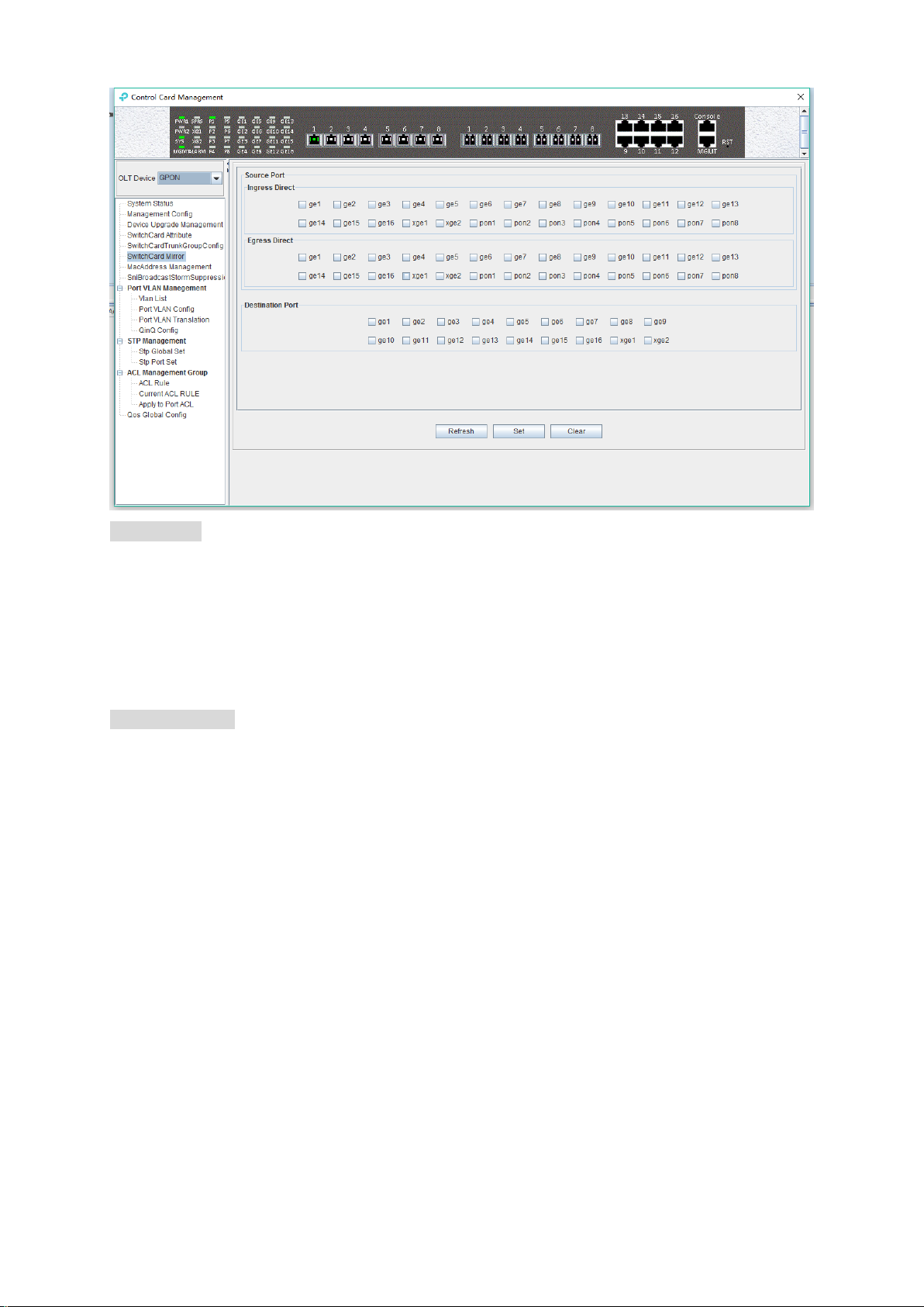
6.2.5 OLT trunk(LACP) Configuration
The device supports the link aggregation protocol LACP which conforms to the IEEE802.3 ad
standard. The LACP protocol is used to bundle multiple uplink ports together to form a single
logical connection to increase the bandwidth of the link and realize backup functions of uplink port,
which means when a port is broken, other ports can still communicate.
Double click the 'Switch Control Card' icon on the left side of the main interface to open the
16
Page 22

'Control Card Management' window and enter the 'Switch Card Trunk Group Config' page.
The features of OLT LACP are as follows:
Link aggregation function is mainly applied to all uplink port;
The default aggregation group is 16;
All port can be added to a aggregation group;
Support several equalization algorithms based on the source and destination MAC address,
source and destination IP address;
Each port can be assigned to only one aggregation group and cannot be assigned to multiple
aggregation groups at the same time.
LACP Function parameter on EMS are as follows:
Trunk Group ID
Show number of link aggregation groups available by default on OLT, default number is 1-16, link
aggregation groups can’t be added, only can be modified and configured.
Trunk Group Member
Show which uplink port members are already in the link aggregation group.
Trunk Group Name
Name of the link aggregation group.
Trunk Group Policy
Select a strategy of link aggregation negotiation, which can be negotiated in several ways, such as
the source and destination MAC address, source, and destination IP address.
Operation Status
Show the configuration state of the link aggregation group, the 'Up' indicates that the configured
link aggregation group is successful and has taken effect, 'Down' indicates that the configured link
17
Page 23
aggregation group is unsuccessful and hasn’t taken effect.
Actual Speed
Shows the current negotiation rate of the link aggregation group.
Admin Status
Configure the management status of the link aggregation group, 'Up' to enable the link
aggregation group and 'Down' to disable the link aggregation group.
[Example of link aggregation configuration]
Example: Add GE1 and GE3 to link aggregation group 1, named 1234, with source MAC and
destination MAC negotiation.
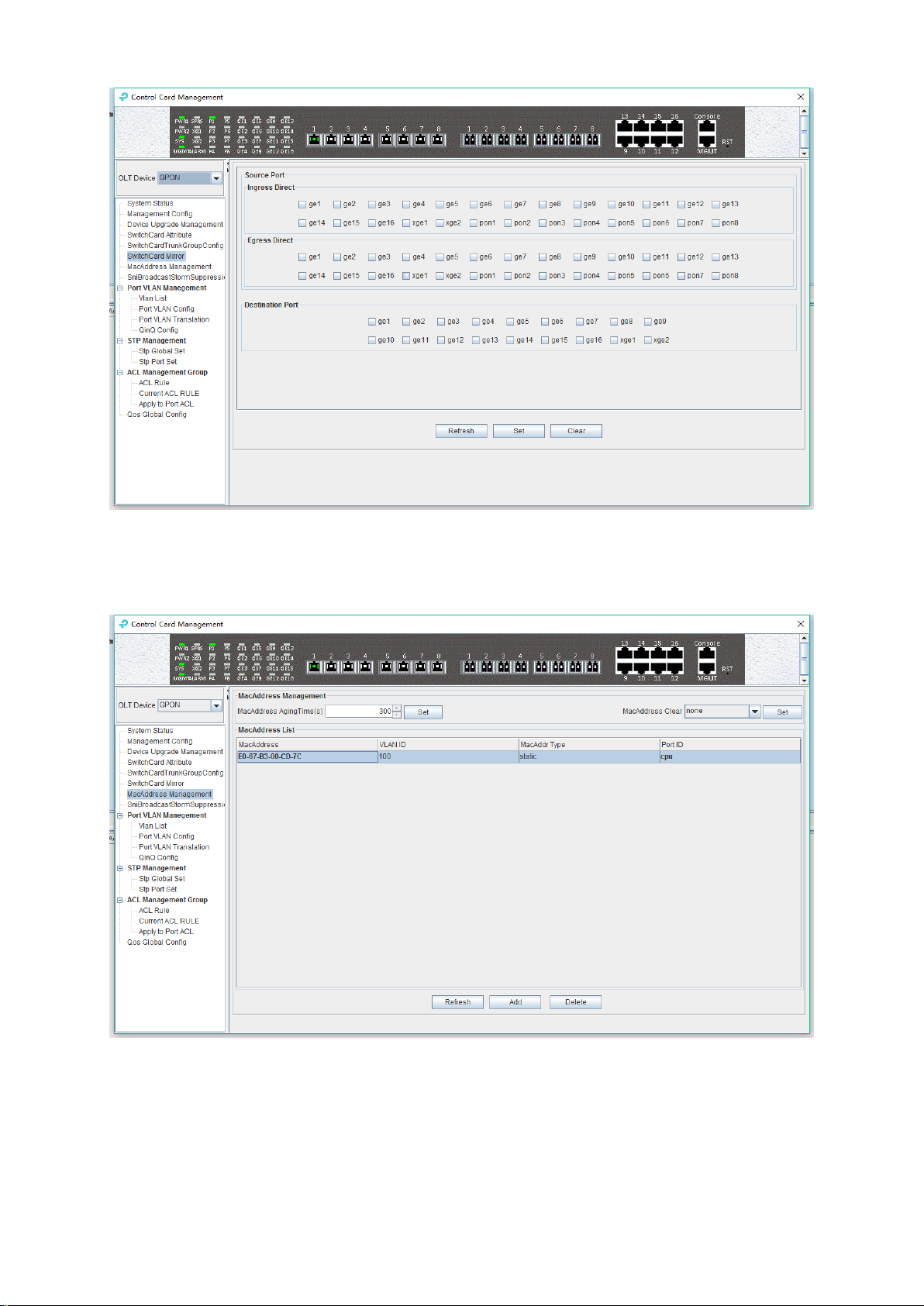
6.2.6 OLT Port Mirror Configuration
Port mirror function is used to copy the packets of Source port to other port (destination port), the
user can monitor the packets which copy to the destination port to monitor network and debug. All
uplink port and PON port can be set to source or destination ports.
Double click the 'Switch Control Card' icon on the left side of the main page to open the 'Control
Card Management' window and enter the 'Switch Card Mirror' page.
18
Page 24
Source port
Specify the source port that needs to be captured and analyzed. User should know the concepts of
'Ingress Direct' and 'Egress Direct' first:
'Egress Direct' means the direction of the packets leave the port; ‘Ingress Direct’ means the
direction the packets enter the port.
When only one direction is checked, OLT will copy packets of one direction to the destination port.
When both directions are selected, all packets are mirrored to the destination port.
Destination port
The port that receives packets of the source port.
The configuration of the ports is as follows:
1) select the source port. All ports can be selected as the source port, each port has 'Ingress
Direct’ and 'Egress Direct'.
2) specify the destination port. You can specify one of the ports as the destination port, and all
source port packets will be forwarded to the specified destination port.
[Example of port mirror configuration]
Example: check ge2 in the 'Ingress Direct' and 'Egress Direct' and select ge8 in 'Destination
port' then click 'Set' button. All traffic of ge2 are mirrored to ge8 port.
19
Page 25
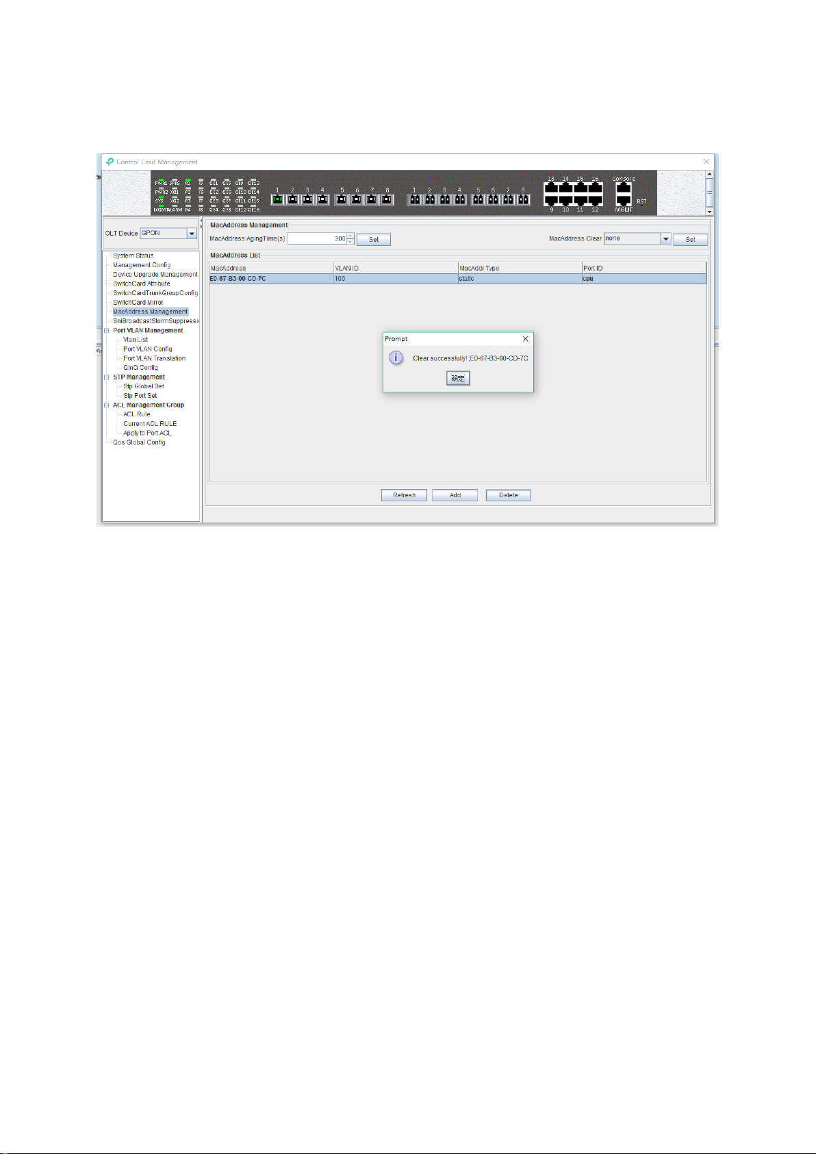
6.2.7 OLT MAC Address Management
Double click the 'Switch Control Card' icon on the left side of the main page to open the 'Control
Card Management' window and enter the 'Mac Address Management' page.
MAC Address Management
MAC address management window is used to configure OLT’s mac address aging time and clear
MAC address, view the MAC address information which OLT has learnt, including MAC address,
VLAN ID, type of MAC address, port ID, parameters are as follows:
Mac address aging time
20
Page 26
Set OLT's MAC address aging time. The MAC address that OLT learned will be cleaned
automatically after this time.
Mac address clear
Choose a type of mac address in ‘Mac Address Clear’ then click the ‘Set’ button, the MAC
address of the specified type will be cleaned.
Mac Address List
The MAC address list mainly displays the MAC address that have learned by OLT, including the
VLAN of the MAC address, the type and the port where the MAC address is learnt. The
parameters we can view or configured in the MAC address list are as follows:
Mac Address
Specified mac address, format as: xx-xx-xx-xx-xx-xx or xx:xx:xx:xx:xx:xx.
VLAN ID
Display the vlan of mac address which from uplink port or pon port and the the vlan which
we set for static mac address.
Mac Addr Type
There are three options, static, blackhole, and dynamic.
Static represents a static MAC address. When the source MAC address of the packet
matches this static MAC address, it will be forwarded. The static MAC address will not
be cleaned after the aging time.
Blackhole represents the black hole of the MAC address. If the source MAC address
of the message is matched with this MAC address, it is discarded and not allowed to
be circulated.
Dynamic represents a MAC address automatically learnt by OLT, it will be cleaned
after the aging time.
Port ID
Show the port which MAC address learned from.
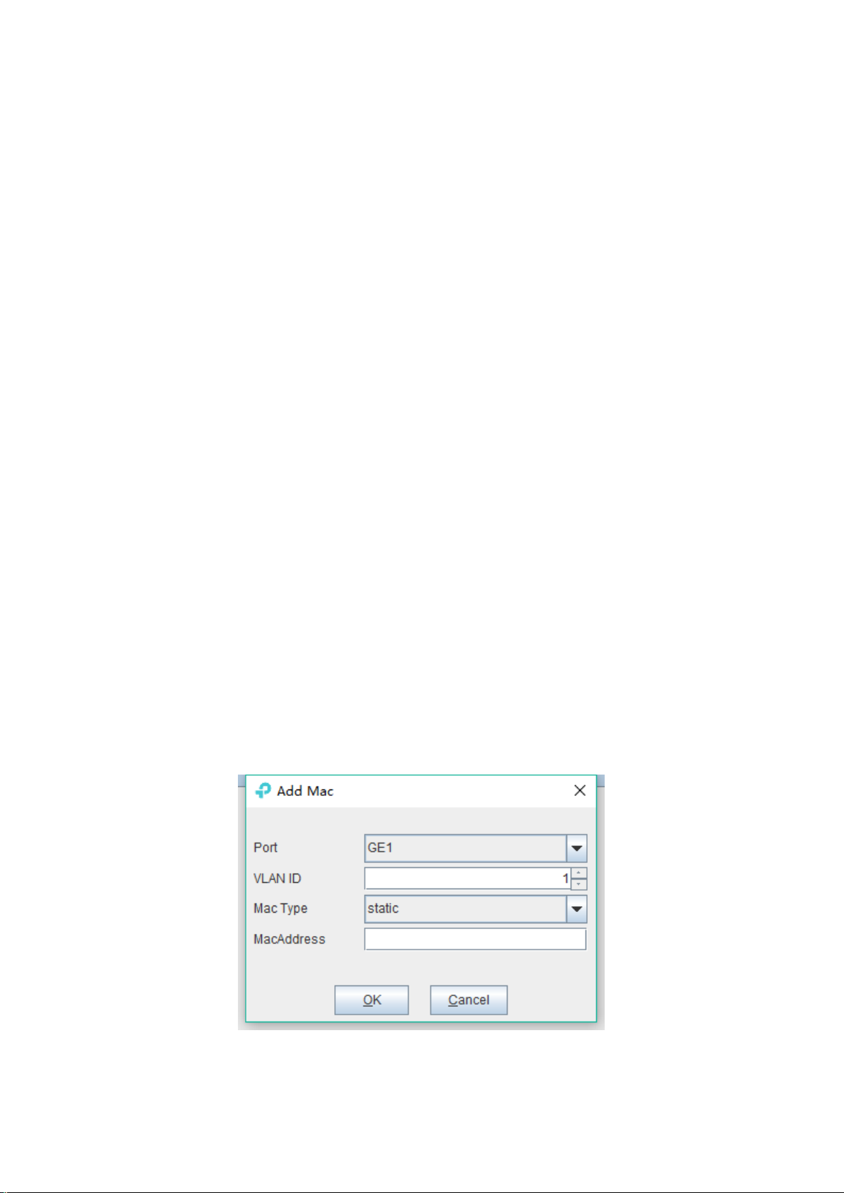
Click the ‘Add’ button to bring up a window of ‘Add MAC’. We can add a static MAC address to
the MAC address table.
After finishing configuration, click ‘Confirm’ button, at the same time, MAC address list will show
21
Page 27
this new added mac-address entry.
‘Delete’ button: Choose a specified mac-address entry in MAC address list, clicking ‘Delete’
button can delete this entry.
Click ‘Refresh’ button to update MAC address list.
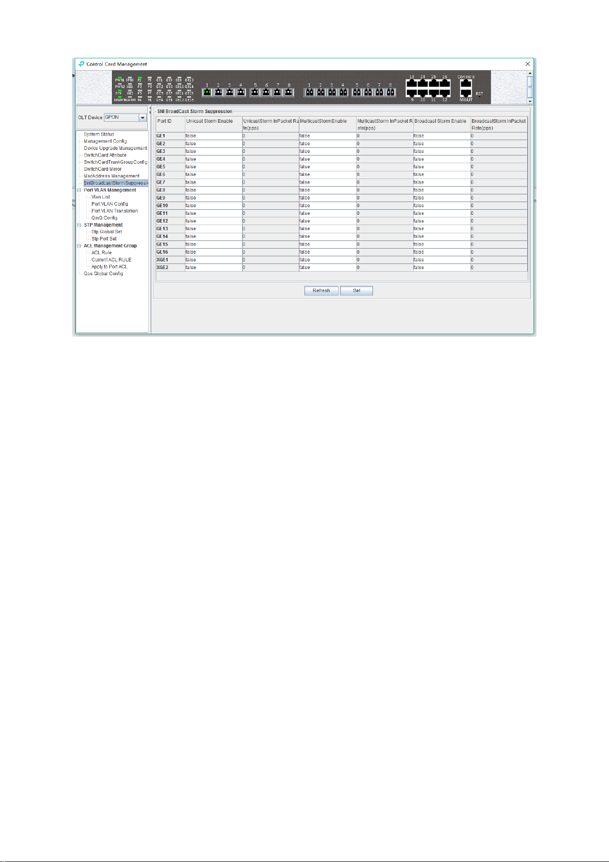
6.2.8 Uplink Port Broadcast Storm Suppression Configuration
Storm suppression function is used to let the uplink port suppress the unicast storms, multicast
storms and broadcast storms to prevent these storms from adversely impacting the network
performance.
Double click the 'Switch Control Card' icon on the left side of the main page, open the 'Control
Card Management' window, enter the 'SNI Broadcast Storm Suppression' management page
configuration.
22
Page 28

Unicast / multicast / broadcast storm suppression enabled
When ‘True’ is selected, the unicast / multicast / broadcast storm suppression function of the port
is enabled.
When ‘False’ is selected, the unicast / multicast / broadcast storm suppression function of the port
is disabled.
Unicast / multicast / broadcast inpacket rate
This parameter is used to configure the packet rate limitation, when the
unicast/multicast/broadcast packet rate is higher than the limitation, the storm suppression
function will be enabled, and the corresponding traffic will be suppressed. The limitation value
should be between 1-1488100 pps.
[Example of storm suppression configuration]
Example: The unicast storm suppression function is set to True and the unicast inpacket rate is
5000 pps. The multicast storm suppression function is set to True and the multicast inpacket rate
to 5000 pps. The broadcast storm suppression function is set to True and the broadcast inpacket
rate to 5000 pps. Click 'Set' button after the configuration, a prompt window will pop up and click
the 'OK' button to complete the configuration.
23
Page 29
6.2.9 OLT Port VLAN Management
VLAN (Virtual Local Area Network), is a kind of technology that logically divided the LAN into
multiple segments based on user demand (functions, departments or applications, etc.) without
considering the physical location of the virtual network. VLAN technology allows a network
administrator to divide a physical network into different logical segments (VLAN), each containing
a set of devices with the same requirements.
The advantage of VLAN technology is that the traffic within a VLAN will not be forwarded to other
VLANs, thus helping to control network traffic, simplify network management and improve network
security.
The VLAN configuration of the GPON system is divided into the VLAN configuration of the OLT
and the VLAN configuration of the ONU part. The VLAN management of the ‘Switch Control
Card’ section refers to the VLAN configuration of the OLT part.
The VLAN function of the OLT part of the TP-Link GPON system is as follows:
Support Port-based VLAN and IEEE802.1Q VLAN.
Support full 4K VLAN group, VID range 1~4094.
VLAN 1 is the system reserved VLAN, it includes all switch ports, all ports are UNTAG mode.
All switch ports, including uplink ports and downlink ports support VLAN Partition.
6.2.9.1 OLT Port VLAN Management
Double click the ‘Switch Control Card’ icon on the left side of the main page, open the ‘Control
Card Management’ window, and enter the 'VLAN List' page. Typical page is as follows:
24
Page 30
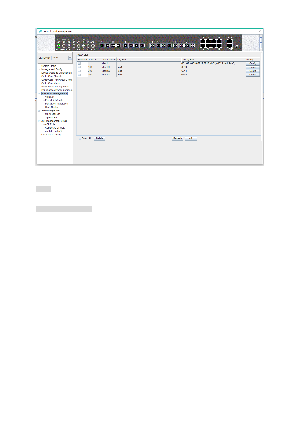
The VLAN list has ‘Selected’, ‘VLAN ID’, ‘VLAN Name’, ‘Tag Port’, ‘Untag Port’, ’Modify’ items.
Here's a brief introduction to these projects:
Select
Use to select a VLAN entry.
VLAN ID / VLAN Name
VLAN ID displays all the VLAN ID that are available on the current OLT. VLAN Name displays the
name of the current existing VLAN.
Tag Port / Untag Port
In the Port of Tag Port, the egress packets will be tagged with a VLAN Tag. In the Port of Untag
Port, the VLAN tag of the egress packets will be stripped off.
6.2.9.2 Modify OLT VLAN
Each VLAN entry has a 'Config' button, which is used to modify the VLAN's 'Tag Mode’ and
‘Member Port' as shown below, click 'Confirm' button to complete the configuration after setting up.
25
Page 31

6.2.9.3 Add OLT VLAN
Here is a ‘Add’ button in the ‘VLAN List’ page. Click the button to add a VLAN ID to the OLT, and
the configuration completes after click 'OK' button.
6.2.9.4 OLT Port VLAN Configuration
Double click the ‘Switch Control Card’ icon on the left side of the main page, open the ‘Control
Card Management’ window, and enter the port 'VLAN Configuration' page. Typical page is as
follows.
26
Page 32

Port ID
Displays the corresponding port number, GE represents the uplink port, XGE represents the
Gigabit port, PON represents the PON interface.
VLAN Priority
Displays the priority of the current port VLAN, which shows the value of 0-7, the minimum priority
of 0, and the highest priority of 7.
Port VLAN(PVID)
Displays the default VLAN for the current port, which shows the value of 1-4094. If you want to
configure the VLAN of a port to a new one, you need to make sure the new VLAN is added to the
OLT already.
VLAN Mode
Displays the VLAN mode of the current port, where the modes that can be displayed are: access,
hybrid, trunk.
Modify
Double click the ‘Config’ button to configure the VLAN priority, port VLAN ID(PVID), and VLAN
mode of the corresponding port. Click the ‘Set’ button to complete the configuration. As shown in
the following figure.
27
Page 33

VLAN
mode
Actions (in the ingress direction)
Actions (in the
egress direction)
Untagged
packet
Tagged packet
Access
Tag the packet
with the PVID.
If the VLAN ID of
received packet is
the same as the
PVID.
Drop the packet if its
VLAN ID is different
from the PVID.
Remove the VLAN ID and
tag and send out the packet.
Trunk
Tag the packet
with the PVID.
Receive the packet if
its VLAN is carried on
the port.
Drop the packet if its
VLAN is not carried
on the port.
Removing the tag and
send out the packet if its
VLAN ID is the same as
the PVID of this port.
Send out the packet
without removing the tag if
its VLAN is carried on the
port but is different from
the PVID.
Hybrid
Drop the packet if its
VLAN is not carried on the
port.
The packets in different VLAN modes are handled as follows:
28
Page 34

If the VLAN of the packet
is carried on the port, send
the packet out. The VLAN
tag of the packet will be
removed if the port is
configured as UNTAG in
this VLAN. And the VLAN
tag will be kept if the port
is configured as TAG in
this VLAN.
6.2.9.4.1 OLT Port Access Mode VLAN Configuration
Example: Configure GE1 port as access mode, priority is 2, PVID is 100. The steps are as follows:
(PON port configuration is the same)
Step 1:
Double click the ‘Config’ button in the column of GE1 in the port VLAN configuration page.
Step 2:
At this point, the Port VLAN Config page will appear as follows. Set the VLAN priority to 2, the
PVID to 100, and the VLAN mode select to access. Then click the ‘Set’ button and click the ‘OK’
button to complete the configuration.
29
Page 35

Step 3:
Click the 'Back' button to view the modified configuration.
6.2.9.4.2 OLT Port Trunk Mode VLAN Configuration
Example: Configure GE3 port as trunk mode, priority is 3, PVID is 200, trunk VLAN is101-103.
The steps are as follows:
Step 1:
Double click the ‘Config’ button in the column of GE3 in the port VLAN configuration page.
30
Page 36

Step 2:
At this point, the following page will appear. Firstly, change the VLAN Mode to trunk in this page.
Step 3:
Then, set the VLAN priority to 3, the PVID to 200, Click the “Set” and then click “OK” in the pop-up
window.
31
Page 37

Step 4:
Click ‘Add’ button, add '101-103' at the 'Add Trunk VLAN' window and click the ‘OK’ button, then
click “OK” button in the pop-up window to complete the configuration.
Step 5:
Click ‘Back’ button to view modified configurations.
6.2.9.4.3 OLT Port Hybrid Mode VLAN Configuration
32
Page 38

Example: Configure GE4 port as hybrid mode, priority is 4, PVID is 300, The hybrid mode allows
VLAN 301 with tag, VLAN 302 without tag. The steps are as follows:
Step 1:
Double click the ‘Config’ button in the column of GE4 in the port VLAN configuration page.
Step 2:
At this point, the following page will appear. Firstly, switch VLAN mode into hybrid mode in this
page.
Step 3:
33
Page 39

Then, set the VLAN priority to 4, the PVID to 300, Click the “Set” and then click “OK” in the pop-up
window.
Step 4:
The allowed untag and tag VLAN of the hybrid mode need to be added in the 'VLAN List'. You
can refer to chapter 6.2.9.2 and 6.2.9.3.
Add VLAN 301 with tag:
Add VLAN 302 with untag:
34
Page 40

6.2.9.5 OLT Port VLAN Translation Configuration
The OLT port VLAN translation means the CVLAN from the user side (means PON ports) of the
OLT is translated into the SVLAN on the network side (means uplink ports). Details are as follows.
Double click the ‘Switch Control Card’ icon on the left side of the main page, turn on the ‘Control
Card Management’ window, and enter the ‘Port VLAN Translation’ page. Typical page is as
follows.
Port VLAN Translation page can be used to view and configure the port, CVLAN ID, and SVLAN
ID. The following will be a brief introduction.
35
Page 41

Port
Display the corresponding port number, GE represents the uplink port, XGE represents the 10G
port, PON represents the PON interface, the serial number represents the number of ports.
CVLAN ID
Represents the VLAN before the translation (VLAN of the PON port), with a value of 1-4094.
SVLAN ID
Represents the converted VLAN (VLAN of the uplink port), with a value of 1-4094.
‘Set’ button
When you have configured the above items, you can click the ‘Set’ button to complete the
configuration. At this point, the translate item will appear in the VLAN translation list.
‘Delete’ button
Select the entry you want to delete in the VLAN translation list and click the ‘Delete’ button to
delete the specified entry.
[Example of VLAN Translation Configuration]
Example: Converts a packet with a VLAN of 100 on the user side of the GE1 port to VLAN 200 on
the network side. The configuration steps are as follows.
Step 1:
Click on the 'Port VLAN Translation', Select GE1 in the right page, CVLAN set to 100, SVLAN set
to 200, click on the following 'Set' button, and then click the 'OK' button in the 'Prompt' window to
complete the configuration.
Step 2:
Click the 'Refresh' button to view the VLAN translation list that you just configured.
36
Page 42

6.2.9.6 OLT Port QinQ VLAN Configuration
QinQ technology (also known as Stacked VLAN or Double VLAN). The standard is from IEEE
802.1ad, which encapsulates the user's private VLAN tag in the public VLAN tag, so that the
packet carries the two-layer VLAN tag through the operator's backbone network (public network).
QinQ technology effectively extends the number of VLAN by stacking two 802.1Q headers in
Ethernet frames so that the number of VLAN can be up to 4096x4096.
TP-Link GPON QinQ configurations are mainly accomplished in the PON Port.:
Double click the 'Switch Control Card' on the left side of the main page to open the 'Control
Card Management' window and enter the 'QinQ Config' page. The typical page is as follows.
37
Page 43

The QinQ config window can be used to view and configure the PON port ID, Start VLAN ID, End
VLAN ID, Outer VLAN ID, and Outer VLAN Priority. The following will be a brief introduction.
Port Name
Displays the corresponding port number, PON represents the PON interface, the serial number
followed by represents the port number.
Start VLAN ID, End VLAN ID, Outer VLAN ID
Start Customer VLAN ID (CVLAN):Represents the initial VLAN ID (when entering the PON port) of
the inner layer VLAN, with the value of 1-4094;
END Customer VLAN ID (CVLAN):Represents the termination VLAN ID (when entering the PON
port) of the inner layer VLAN, with a value of 1-4094;
Service provider VLAN (SVLAN): Represents another layer of VLAN after the inner layer VLAN,
with a value of 1-4094;
When a packet enters the PON port with the VLAN ranges from the start VLAN to the end VLAN, a
layer of outer VLAN (SVLAN) is added to the packet, and the packet at this time is a packet with
double layer VLAN.
SVLAN Priority
Represents the priority of SVLAN, with a value of 0-7, in which 0 is the lowest priority and 7 is the
highest priority.
‘Add’ button
Click the 'Add' button pops up the window as shown below. In this window, you can configure the
start CVLAN, end CVLAN, SVLAN, and priority. Click ‘OK’ button to complete the configuration.
38
Page 44

‘Set’ button
When you have added all the items, you can click the ‘Set’ button to complete the configuration.
‘Delete’ button
Select the items to be deleted in the QinQ config list, and then click ‘Delete’ button to delete the
specified entry.
[Example of VLAN QinQ Configuration]
Example: PON 8 received VLAN100-103 packets are marked with a layer of outer VLAN 200, the
priority of 0.
Step 1:
Click the 'Add' button, pop up the 'Add QinQ' window, configure the start VLAN to 100, end VLAN
to 103, SVLAN to 200, the priority to 0. Then click 'OK'.
Step 2:
Click the 'OK' button in the prompt window that appears.
39
Page 45

At this point, we can see our newly added QinQ entries in the QinQ config list.
6.2.10 OLT STP Management
STP is the abbreviation of spanning tree protocol. The protocol can be applied to the loop network,
through a certain algorithm to achieve path redundancy, while the loop network is trimmed into a
loopless tree network.
The main application of the spanning tree protocol is to avoid the network loopback in the LAN and
solve the "broadcast storm" problem of the ring-to-ring Ethernet network. In a sense, it is a kind of
network protection technology that can eliminate the loop connection caused by mistake or
accident.
40
Page 46

6.2.10.1 STP Global Config
Double click the 'Switch Control Card' icon on the left side of the main page, open the 'Control
Card Management' window and enter the 'STP Global Set' window of ‘STP Management’.
As shown above, in ‘STP Global Set’ page, you can view the STP Version, Priority, Time Since
Topology Change, Topology Change Times, Designate Root , Root Cost, Root Port, Max Age
Time(s), Hello Time(s), Hold Time(s), Forward Delay(s), Bridge Tx Rate(kbps)and STP Enable
State. Among them, Priority, Max Age Time(s) ,Hello Time(s) , Forward Delay(s), Bridge Tx
Rate(kbps) and STP Enable State can be modified . Specific parameters are introduced as follows:
STP Global Set
STP Version
The default setting of system is RSTP.
Priority
Bridge priority is used to select the root bridges of the network. The smaller the value, the higher
the priority, the greater chance of being selected as the root bridge. You can set a bridge with a
priority value of 0, 4096, 8192, 12288,16384, 20480, 24576, 28672, 32768, 36864, 40960, 45056,
49152,53248, 57344 and 61440.
Time Since Topology Change
The duration of switching from the previous topology state to the current state.
Topology Change Times
The number of topology changes caused by the change of the port or link state in the network
topology.
Designate Root
You can designate root bridge through bridge priority. In case of not designating priority, the
smaller the MAC address, and the greater the chance of being the designated root bridge.
41
Page 47

Root Cost
To calculate the link cost, the port with the lowest root link cost will become the forwarding port in
case of forwarding the same network bridge ID. The legal range is 1 ~ 20000000.
Root Port
The number of ports that are passed by the path of from non-root bridge to the root bridge.
Max Age Time
The lifetime of the BPDU message received from the adjacent bridge of Designated port. The legal
range is 6~40, in s.
Hello Time
Set the bridge how often to send a BPDU message. The setting range time is 1~2, in s.
Hold Time
When the network bridge changes in topology, maintaining the time of monitoring and learning
state before sending packets.
Forward Delay
With downward compatibility STP network bridge, for port of working in the STP mode, forwarding
delay timer designated the port before the transition to the learning state the time of in discarding
state, and before the learning state transition to the forwarding state in the time of learning state.
The legal range is 4~30, in s.
Bridge Tx Rate
Set the number of maximum sending BPDU messages in 1 second. The setting range of 1~10, in
frame/s.
STP Enable State Configuration
Open or close the RSTP function by setting the 'RSTP State’ to ‘Enable’ or ‘Disable’.
Note: When you set Max Age Time, Hello Time, Forward Delay, first input setting value, then click
‘Set’ button, finally click ‘Refresh’ button, thus configuring successfully. And consistent with three
contents shown below.
6.2.10.2 STP Port Config
Double click the 'Switch Control Card' icon on the left side of the main page, open the 'Control
Card Management' window and enter the 'STP Port Set' window of ‘STP Management’.
42
Page 48

As shown above, in ‘STP Port Set’ page, you can view Device ID, Port Status, Port Priority, Port
Path Cost, Designated Root ID, Forward Transitions, Protocol Migration Enable, Edge Port Admin
Status, Edge Port Oper Status, Port Point to Point Admin Status, Port Point to Port Oper Status
and Port STP Enabled Status. In addition, you can modify Port Priority, Port Path Cost, Protocol
Migration Enable, Edge Port Admin Status and Port Point to Point Admin Status. Specific
parameters are introduced as follows:
Port Status
STP Port Status has five types, including disable, learning, listening, forwarding and blocking.
Disable: In the invalid status, to be a valid port, first switch to the blocking port.
Learning: In the learning state, the port is adding addresses to its forwarding database, but does
not forward packets.
Listening: In the listening state, the port is waiting to receive BPDU packet, and BPDU may tell the
port to return to the blocking state.
Forwarding: In the forwarding state, the port is forwarding the packet.
Blocking: In the blocking state, the port is blocked and can not forward or receive packets.
Port Priority
When the link cost and the sending network bridge ID is the same, the lowest priority port will be
the forward port. The parameter value can be set to 0 ~ 440, and the step length is 16.
Designated Root ID
The BID in the BPDU message consists of two parts, the bridge priority and the bridge MAC. The
bridge ID is only. Switches selects the smallest BID switch as the root bridge in the network.
Forward Transitions
The port consists of five status. Status transitions need to go through status transition time.
Protocol Migration Enable
43
Page 49

This means that the device supports RTSP, and if the port is enabled, the port will automatically
migrate to STP compatible mode when the port is connected to the device running the STP
protocol. 'True' means opening this function, and 'False' means closing this function.
Edge Port Admin Status
You can use this option to set whether it is an edge port. 'Edge' is an edge port, and ‘NEdge’ is a
non - edge port.
Edge Port Oper Status
This option indicates whether the current port is in the edge port state. ‘False’ indicates that the
port is not in an edge state, and ‘Ture’ indicates the status of the port on the edge. The edge port
does not need to go through the ‘Discarding-learning-forwarding’ step and directly switch to the
forwarding status.
Port Point to Point Admin Status
You can use this option to set whether the port is a point-to-point port, including 'Auto', 'Ture' and
‘False’ three options. 'Ture' is to set this port to point-to-point port, and 'False' is to set this port to
non point-to-point port. ‘Auto’ is dependent on the STP protocol itself. Point-to- point ports allow
fast switching to forwarding status, and non point-to-point ports need to go through
discarding-learning-forwarding step to switch to forwarding status.
Port Point to Port Oper Status
The option is to specify the point-to- point port state in which the current port is actually located.
Prompt: Some of the parameter explanations are described in the previous section, which are not
repeated here. You can go to the previous section to inquire.
6.2.11 ACL Management
ACL is ‘Access Control List’. Through configuring a serial of matching rules to filter specific data
packets, thus identifying objects that needs to be filtered. After identifying specific objects,
according to preset policy permitting or denying the corresponding data packets pass. The
process of ACL filter message flow prepares for QoS.
6.2.11.1 Configuration ACL Rule
ACL has three types, including basic ACL, its Id range from 2000 to 2999, only matching source IP
address; advanced ACL, its Id range from 3000 to 4999, being able to matching source IP address,
destination IP address, source port, destination port, DSCP and IP message type; link ACL, its Id
range from 5000 to 5999, being able to match source mac, destination mac, VLAN Id and Ethernet
type.
6.2.11.1.1 Basic ACL Configuration
Double click the 'Switch Control Card' icon on the left side of the main interface, open the
'Control Card Management' window and enter the 'ACL Rule' window of ‘ACL Management’
page. Click the pull-down menu of ACL Type, and choose basic acl(2000-2999) option.
44
Page 50
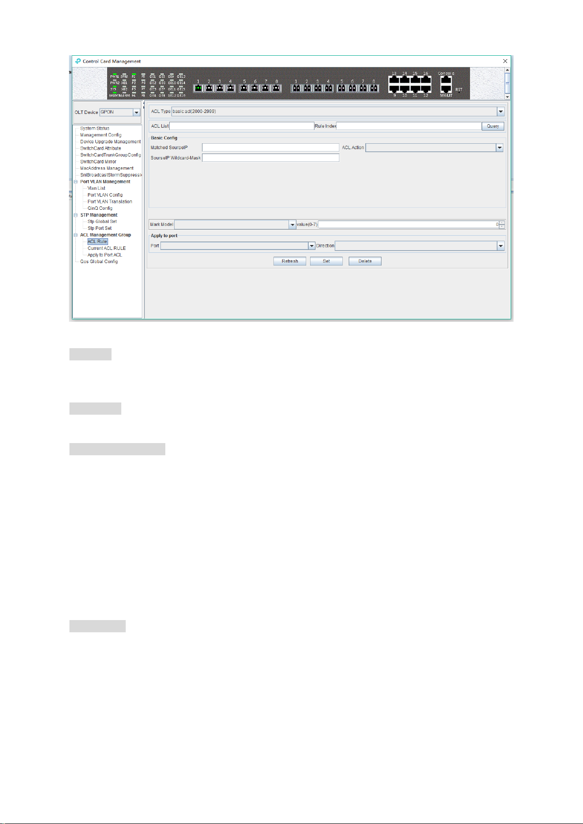
As above ‘Basic ACL’ page, you can set the following configuration parameters:
ACL List
ACL List,the set of ACL entries, this can inquire one of ACL according to inputting ACL Id and rule
id.
Rule Index
ACL Rule Index,also rule id, and the range of value is 1-16.
Basic configuration
Matched source IP
Configure matched source IP address of ACL Rule, in this format: A.B.C.D.
ACL Action
ACL Action configuration, including ‘permit’, ‘deny’ and ‘mark’ three options, indicates specific
parameters of permitting or denying matching.
Source IP Wildcard-Mask
Configure matched source IP Wildcard-Mask address of ACL Rule. IP Wildcard-Mask address is
reverse address of IP sub-net mask. Example for: IP is 192.168.5.123, and its IP Wild-Mask is
0.0.0.225.
Mark Model
This is Mark Model, only applied in when ACL Action is ‘mark’, including ‘null’ , ‘802.1p’ , ‘VLAN
id’ ,’ TOS PRECEDENCE ’ and ‘ DSCP ’ .
802.1p
For the traffic priority LAN level 2 QoS/CoS protocol, the protocol header includes a 3-bit priority
field with a value range of 0-7, which supports grouping packets into various traffic types.
VLAN id
45
Page 51
VLAN identifier,with a value range of 0-4094.
TOS PRECEDENCE
TOS is a field of IP Message, with indicating type of service. PRECEDENCE is a 3bit field in TOS
to indicate IP priority with a value range of 0-7.
DSCP
DSCP is ‘Differentiated Services Code Point’, Which provides the standard of differentiated
service for QoS with a 6bit field, the value range is 0-63.
Apply to port
Port
ACL Rule applies to ports, including uplink ports and PON ports.
Direction
ACL Rule applies to direction of port, including ‘ingress’ and ‘ egress’.
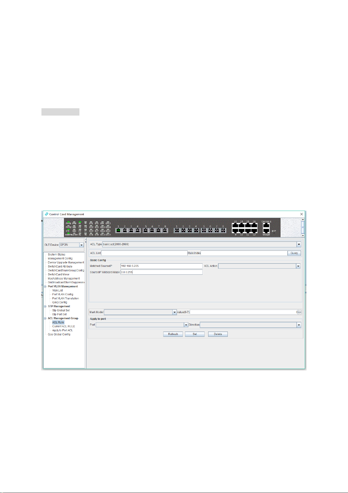
[Example of Basic ACL configuration]
Example:Configure a basic ACL, and ID is 2001. Source IP is 192.168.5.205, and Rule Action is
‘permit’, as show below:
After completing those configurations, the configuration takes effect through the 'Set' button at the
bottom of page, thus creating a basic ACL Rule successfully. Deleting a ACL rule created through
the ‘Delete’ button. Updating a ACL Rule created through the ‘Refresh’ button.
6.2.11.1.2 Advanced ACL Configuration
Double click the 'Switch Control Card' icon on the left side of the main interface, open the
'Control Card Management' window and enter the 'ACL Rule' window of ‘ACL Management’.
Click the pull-down menu of ACL Type, and choose advanced acl(3000-4999) option.
46
Page 52

As above ‘Advanced ACL Rule’ page, compared with ‘Basic ACL Rule’ page, also set the
following configuration parameters.
Basic configuration
Matched destination IP
Configure matched destination IP address of ACL Rule, in this format: A.B.C.D.
Matched source port
Configure matched source port Id of ACL Rule to match IP Protocol to TCP/UDP, ranging from 0 to
65535.
Matched destination port
Configure matched destination port Id of ACL Rule to match IP Protocol to TCP/UDP, ranging from
0 to 65535.
Matched DSCP
Configure matched DSCP of ACL Rule. DSCP is ‘Differentiated Services Code Point’. In the TOS
identification byte of each data packet IP header, taking advantage of used 6 bit and unused 2 bit
to prioritize by coding value. DSCP user 6 bit, the value range of 0-63.
Matched IP Message Type
Configure matched IP Message Type of ACL Rule, including IP, ICMP, IPINIP, UDP, TCP and so on,
the value range of 0-255.
Matched Destination IP Wildcard-Mask
Configure matched destination IP Wildcard-Mask address of ACL Rule. IP Wildcard-Mask address
is reverse address of IP sub-net mask. Example for: IP is 192.168.5.205, and its IP Wild-Mask is
0.0.0.255.
[Example of Advanced ACL configuration]
Example:Configure an advanced ACL, and ID is 3001. Rule Action is ‘Permit’, as show below:
47
Page 53

After completing those configurations, the configuration takes effect through the 'Set' button at the
bottom of page, thus creating an advanced ACL Rule successfully. Deleting a ACL rule created
through the ‘Delete’ button. Updating a ACL Rule created through the ‘Refresh’ button.
6.2.11.1.3 Link ACL Configuration
Double click the 'Switch Control Card' icon on the left side of the main interface, open the
'Control Card Management' window and enter the 'ACL Rule' window of ‘ACL Management’.
Click the pull-down menu of ACL Type, and choose link acl(5000-5999) option.
As above ‘Link ACL Rule’ page, compared with ‘Basic and Advanced ACL Rule’ page, also set
the following configuration parameters.
48
Page 54

Basic configuration
Matched source MAC
Configure matched source MAC address of ACL Rule, only applied in link ACL Rule, in the format:
AA-BB-CC-DD-EE-FF
Matched destination MAC
Configure matched destination MAC address of ACL Rule, only applied in link ACL Rule, in the
format: AA-BB-CC-DD-EE-FF。
Match VLAN Id
Configure matched VLAN of ACL Rule, only applied in link ACL Rule. The value range of Id is
1-4094.
Match Ethernet Type
Configure matched Ethernet data frame type of ACL Rule, only applied in link ACL Rule, including
IP(2048), ARP(2054), SNMP(33100), mpls-unicast(34887), mpls-multicast(34888) and so on.
Matched source MAC wildcard mask
Configure matched source MAC wildcard mask of ACL Rule, only applied in link ACL Rule. MAC
wildcard mask of a single host is 00-00-00-00-00-00. MAC wildcard mask of any host is
FF-FF-FF-FF-FF-FF.
Matched destination MAC wildcard mask
Configure matched destination MAC wildcard mask of ACL Rule, only applied in link ACL Rule.
MAC wildcard mask of a single host is 00-00-00-00-00-00. MAC wildcard mask of any host is
FF-FF-FF-FF-FF-FF.
[Example of LINK ACL configuration]
Example:Configure a link ACL, and ID is 5001. Add outer VLAN 500 to MAC address. As shown
below:
49
Page 55

After completing those configurations, the configuration takes effect through the 'Set' button at the
bottom of page, thus creating a link ACL Rule successfully. Deleting a ACL rule created through
the ‘Delete’ button. Updating a ACL Rule created through the ‘Refresh’ button.
6.2.11.2 View OLT ACL Rule
Double click the 'Switch Control Card' icon on the left side of the main interface, open the
'Control Card Management' window and enter the ' Current ACL Rule' window of ‘ACL
Management’ page.
As shown in the figure above, you can view the previously created ACL rule entries on the 'Basic
Configuration' page, where the contents are set in this page. In this page can also delete a ACL,
first select an ACL rules, and then click ‘Delete’ or ‘Delete ACL’ button to delete the ACL rules
which not applied directly to the port, if you want to delete the ACL which has been applied to the
port, can only remove the binding with the port, and then delete. Update the configuration rules
information by the 'Refresh' button.
6.2.11.3 View OLT Port Applied ACL Rule
Double click the 'Switch Control Card' on the left side of the main page to open the 'Control
Card Management' window and enter the 'Apply to Port ACL' window of the 'ACL Management
Group'.
50
Page 56

As above, you can see the ACL that you created and applied to port, including the port number,
ACL ID, and the direction of the application port .Through the ‘delete’ button, you can delete a
ACL rule and update the rule information of the configuration through the ‘Refresh’ button.
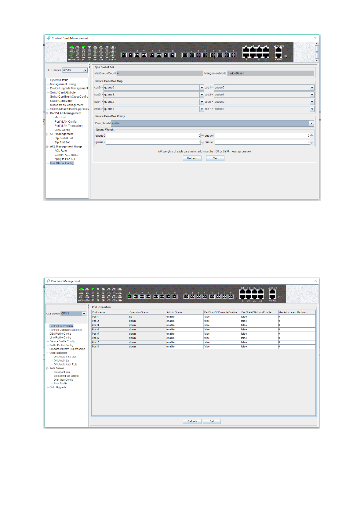
6.2.12 OLT QoS Configuration
QoS Refers to a network can use a variety of basic technology, to provide better services for the
specified network application, is a kind of network optimizing mechanism, is used to solve the
problem of network delay and blocking issue.
Double click the 'Switch Control Card' icon on the left side of the main interface, open the
'Control Card Management' window and enter the 'Qos Global Information' page.
51
Page 57

priority
Cos 0
Cos 1
Cos 2
Cos 3
Cos 4
Cos 5
Cos 6
Cos 7
queue
Queue 0
Queue 0
Queue 1
Queue 1
Queue 2
Queue 2
Queue 3
Queue 3
‘Qos Global Information’ management page mainly can configure ‘Device BaseQos Map’,
‘Device BaseQos Policy’, ’Queue Wieght’ and ‘Queue Bandwidth’. The parameters are described
as follows:
Qos system parameter
Max queue count
System sets max queue count to 4. it’s range from queue 0 to queue 3.
Qos management mode
System set Qos management mode to deviceBased.
Device BaseQos Map
Qos mapping table is corresponding relationship between priority and port queue. This can
configure queue corresponding to the priority. The fault configuration is showing in the following
table:
Device BaseQos Policy
Queue schedule has three modes, including sp-strict priority, WRR- Weighted Round Robin and
SP+WRR. The details are follows.
SP
Applying this mode, the system is scheduled to be dispatched strictly according to the priority of
queue. Only when the high-priority queue is empty, the packets of the low priority queue can be
dispatched.
WRR
Applying this mode, it needs to configure a weight for each queue, according to the weight
between the queue scheduling in turn, ensure each queue can have a certain amount of services.
When the priority is the same, the weight is not the same, the larger the weight of the queue, the
longer the scheduling time.
SP+WRR
This mode combines the advantages of SP and WRR, and adopts SP mode when dealing with
some critical business, and adopts WRR mode when dealing with some business with low realtime requirement.
Queue weight
Applying in the WRR and SP+WRR two modes, the sum of four queue weight is required to be
100. And in the WRR mode, the value of weight can`t be set to 0.
Queue bandwidth
Set the size of bandwidth occupied by each queue, its range from 0kbps to 1024000kbps.
[Example of QoS configuration]
Example:Set Qos schedule mode to SP, the specific configuration is shown below:
52
Page 58

Example 2:Set Qos schedule mode to WRR, the specific configuration is shown below:
Example 3:Set Qos schedule mode to SP+WRR, the specific configuration is shown below:
53
Page 59
Note: In the WRR mode, the value of weight can`t be set to 0. If the value of weight has 0, Qos
schedule mode is SP+WRR.
6.3 OLT PON Card Management
This section introduces OLT PON Card Management function.
Double click the ‘PON Module’ icon on the left side of the main page and enter the 'PON Card
Management' window. The typical page is shown below:
Through this window the user can do the following management:
Some basic management of PON port of OLT;
PON port storm suppression configuration;
54
Page 60

all kinds of template (DBA profile, line profile, service profile, traffic profile);
Pots Server configuration
ONU upgrade
Authenticate the registration of the ONU;
View the optical power information of the PON port;
The following sections describe the functional modules involved in the PON card management
window.
6.3.1 OLT PON Port Basic Configuration
Double click the ‘PON Module’ icon on the left side of the main page to enter the 'PON port
information' page of the 'PON card management window':
The 'PON port information' property page configures and views the PON port property
parameters of the OLT. The parameters are described below:
Port Name
Displays the PON port name on the OLT. This parameter is unchangeable.
Operation Status
Display the current PON port operation state, the status displays as ‘UP’ when connects to an
ONU or the ONU has registered under the PON port; the state displays as ‘Down’ when not
connected or the ONU unregistered under the PON port.
Admin Status
You can configure the PON port of the OLT to be enabled or disabled. Configure ‘Enable’ to turn
on the PON port; Configure ‘Disable’ to turn off the PON port; The default status is ‘Enable’.
PerfStats Of 15minutes Enable
Displays the management status of the “15 minutes performance statistics”, administrators can
configure this parameter to 'True' or ‘False'.
When set to 'True', the corresponding PON port will report the performance statistics information
55
Page 61

every 15 minutes.
PerfStats Of 24hour Enable
Shows the management status of the “24 hours performance statistics”, administrators can
configure this parameter to 'True' or 'False'.
When set to 'True', the corresponding PON port will report the performance statistics information
every 24 hours.
MacAddr Learn MaxNum
Configure the maximum number of MAC addresses can be learned by the corresponding PON
port of the OLT, in the range of 0 to 8092.
6.3.2 PON Port Optical Module Information
Double click the ‘PON Module’ icon on the left side of the main page to enter the 'PON port
optical module info' page of the 'PON card management window':
Enter this page to view the status of the PON port optical module, includes the temperature,
voltage, current, vendor information, transmit power, etc.
6.3.3 OLT DBA Profile Configuration
OLT profile is used to limit upstream bandwidth of each service of the ONU. This section mainly
describes how to view, create, modify and delete DBA profile.
6.3.3.1 View DBA Profile
Double click the ‘PON Module’ icon on the left side of the main page to enter the 'DBA Profile
Config' page of the 'PON card management' window, you can view fault DBA profile and created
DBA profile:
56
Page 62

The parameters are described below:
DBA profile
Display configured DBA Profile ID, and DBA profile ID is unique.
DBA profile name
Display the name of the configured DBA Profile.
DBA Type
Display configured DBA profile type, there are 5 types of DBA can be chosen, including `fix`,
`assure` , `assure+max` , `max` , `fix+assure+max` .
Fix Rate
Configure and display uplink DBA fix bandwidth. The unit is kbps.
Assure Rate
Configure and display uplink DBA assure bandwidth. The unit is kbps.
Max Rate
Configure and display uplink DBA max bandwidth. The unit is kbps.
Number of mapping rules
Display how many T-CONTs are binding with this DBA profile.
6.3.3.2 Create DBA Profile
In the page of ‘DBA Profile Config’, click ‘Add’ button to pop up ‘Add DBA Profile’ window:
57
Page 63

The page can create an uplink DBA profile, specified DBA profile id, DBA profile name, DBA profile
type and configure the corresponding uplink data rate. Then click ‘OK’ to create the DBA Profile.
[Example of DBA Profile configuration]
Example: Create a DBA Profile that its ID is 50, name is ‘up speed limit’, and type is 100M fix
bandwidth.
6.3.3.3 Modify DBA Profile
In the page of ‘DBA Profile Config’, users can modify some parameters of the DBA Profile, then
click ‘set’ button to let the new parameter take effect.
58
Page 64

6.3.3.4 Delete DBA Profile
In the 'DBA Profile config' page, you can also delete some DBA profiles by select it then click
`delete’ button.
6.3.4 Line Profile Config
The GPON ONU line profile describes the binding relationship between the T-CONT and DBA
profiles, the QoS model of the business traffic and the mapping relationships between the GEM
Port and ONT side business.it is mainly used to configure DBA, T-CONT and GEM Port
information, the ONU line correlation property is configured in the line profile, for the same ONU,
you only need to configure once to save the configuration workload. The ONU management mode
whether for OMCI or SNMP, will need to bind the GPON ONU line when adding ONU, and if not
specified, the system will automatically bind ONU to the default line profile 0. After executing
command success, user will enter the corresponding GPON ONU line profile configuration mode
59
Page 65

and set the related properties of the GPON ONU line profile.
6.3.4.1 View line profile
Double click the "PON Module" on the left side of the main page and enter the "line Profile
Configure" page of the "PON Card Management" window, which will show the line profile
created on OLT:
The parameters in the line profile are described in detail below:
Line Profile ID:
Show the ID of line profile, this parameter is unique;
Profile Name:
Show the name of the configured line profile.
Tcont Num:
Show the number of T-CONT in the line profile. currently support maximum 4 T-CONTs. range:
0-3.
Gem Port:
Show the number of GEM port in the line profile, currently support up to 24 GEMs, range: 1-24.
Bind Num:
Show the number of ONUs bound to this line profile.
6.3.4.1.1 Create Line Profile
There are many steps to add a line profile.
Step 1 (create line profile ID):
In 'Line Profile Config’ page, click "add" button will pop up a 'Add Line Profile’ window, in the
window input customized Line Profile ID, Profile Name and click ‘OK’:
60
Page 66

Step 2 (create T-CONT id)
In ‘Line Profile Configure’ page, double-click the 'Detailed' button in the line of the line profile
you want to configure, then you can enter the 'Tcont Config' page;
In the 'Tcont Config' page, click 'Add' to add a T-CONT. Input Tcont id, and select one DBA profile
to bind, then click `OK` to add it.
61
Page 67

Step 3 (create GEM port) :
In the 'Tcont Config' page, double-click the 'Detailed' button in the line of the T-CONT you want
to configure, you can enter the 'Gem Config' page,
In the 'Gem config' page click 'Add' to add a GEM port, input the Gem id, and then bind a traffic
profile of up and down (the default doesn’t have to bind the traffic profile). Click `OK` to add the
GEM port:
62
Page 68

In this page, double-click the 'Detailed' button below the 'Operation' to enter the 'Gem Mapping’
page and create the gem mapping. Select a gem port, and then click ‘Delete’ to remove a gem
port; You can select vlan, vlan priority and vlan + priority, and then click ‘Set’.
Step 4(create GEM mapping ) :
In ‘Gem Configure’ page, double-click the 'Detailed' button in the line of the GEM you want to
config, then you can enter the 'Gem Mapping’ page.
In the ‘Gem mapping’ configuration page, click 'Add' to add a GEM mapping. Input the Gem Map
id and the Map vlan, then click `OK` to add the GEM mapping item:
63
Page 69

In this page, user can select an entry, then click 'Delete' to remove a GEM mapping.
Now, we complete the creation of the line profile, we can click the 'Back' button back to the Line
Profile page and view the created line profile. (refer chapter 6.3.4.1)
6.3.4.2 Modify Line Profile
The name of the line profile can be modified in the Line Profile page.
Double-click the 'Detailed' button in the line of the line profile you want to modified, we can modify
the T-CONT and GEM of the line profile binding.
6.3.4.3 Delete Line Profile
In the main page of the 'Line Profile', you can select a line profile and click the 'Delete' button to
delete the line profile.
Note: the line profile can only delete the unbound, if the line profile has been bound, the delete
operation of the profile should be done before the ONU is deleted or bound ONU to other line
profile.
64
Page 70

6.3.5 OLT Service (business) Profile Configuration
The GPON ONU service profile provide service profile configuration channel for OLT which use
the OMCI (ONT Management and Control page) method manage.
The ONU service correlation properties are concentrated in the service profile for configuration.
the same business only need to be configured only once to save configuration workload. When
ONU management mode is OMCI
When adding ONU, you need to bind the GPON ONU business profile, which will automatically
bind if not specified will bind the ONU to the default business profile 0. After the command
executes successfully, we enter the corresponding GPON ONU service profile configuration Mode,
we can set the associated properties of the GPON ONU service profile.
6.3.5.1 View Service Profile
Double click the 'PON Module' icon on the left side of the main page and enter the 'Service
Profile Configure' page of the 'PON Card Management' window, which will show the service
profile created on OLT:
65
Page 71

the parameters in the service profile are described in detail below:
Profile id
Show the configured service profile ID, It is unique;
Profile Name
Show the name of the configured service profile.
Eth Num
The number of ONU Ethernet (eth) ports bound to the service profile; The value “Adapt” indicates
that the number of Ethernet ports can be adapted to the ONU, and no manual configuration is
required. For example, the actual number of ethernet ports of the ONU bound to the service profile
is 4, we can select 4 or Adapt.
Pots Num
The number of ONU POTS ports to bind to the service profile, ranging from 0 to 8; The “Adapt”
parameter indicates that the number of post ports can be adapted to the ONU, and no manual
configuration is required. For example, the actual number of actual post ports of the ONU bound to
the service profile is 2, we can select 2 or Adapt.
Catv Num
The number of ONU CATV ports to bind to the service profile, ranging from 0 to 8; The “Adapt”
parameter indicates that the number of CATV ports can be adapted to the ONU, and no manual
configuration is required. For example, the actual CATV port number of the ONU bound to the
service profile is 1, we can select 1 or Adapt.
Bind Num
Shows the times that the service profile is bound by the ONU.
VLAN
Configure the ONU port VLAN for the service profile binding.
IGMP
Configure the ONU port IGMP configuration for this service profile binding.
66
Page 72

6.3.5.2 Create Service Profile
In the 'Service Profile’ in the main page, click "Add" button, specify the service profile ID, name
and number of each port to bind ONU, and then click 'OK' button to complete the basic create for
service profile:
6.3.5.2.1 ONU VLAN Configuration In Service Profile
In the main page of the ‘Service Profile’, double-click the 'Configure' button in the 'VLAN'
column of the entry you want to configure to enter the 'Vlan Configure' page:
The following is a description of VLAN related configuration in service profiles:
select
Select the eth port of ONU.
Profile Id
67
Page 73

Show the service profile of current modified ONU vlan
Port Type
Show the port type of ONU and is shown by default in the name of the eth (Ethernet) port.
Eth Port Id
Show the serial number of the ONU port, and if the ONU is 4, it will appear from top to bottom 1-4.
Vlan Entry Id
The configured VLAN index number, if the port is configured with multiple VLANs, It will be
displayed from 1-x.
Vlan mode
Translation: the translation model here has two meanings:
When the ONU port SVLAN and CVLAN configured under the translation mode are the same, the
configuration is configured with the ONU trunk mode under the VLAN;
When the ONU port SVLAN and CVLAN configured in translation mode are different, the ONU
port VLAN transformation mode is configured to convert the ONU to the SVLAN on the network
side.
QinQ: the port configuration of the ONU is configured with QinQ VLAN mode. In QinQ mode, the
VLAN from ONU is on the outer layer and the VLAN is forwarded to the top. The downstream data
will strip off the outer VLAN tag and then forward it down.
Transparent: the port configuration of the ONU is configured with VLAN transmission mode,
which can be directly forwarded either with VLAN tag or VLAN tag in the VLAN transmission
mode.
Svlan
Configure the SVLAN on the network side for a range of 1-4094.
Svlan priority
Configure priority of the SVLAN on the side of the network, the values range 0-7 and any, 0 has
the lowest priority, and 7 has the highest priority. Any means any priority.
Cvlan
The CVLAN configured on the network side ranges 1-4094.
Cvlan priority
The priority of the CVLAN configured on the network side is 0-7 and any, 0 has the lowest priority,
and 7 has the highest priority. Any indicates any priority.
6.3.5.2.1.1 ONU Transmission Mode VLAN Configuration
In 'service profile' main page, double-click ‘Configure’ button under ‘VLAN’ of the need to
configure, enter the ‘Vlan Configure’ page, in the column of ‘Vlan Mode’ choose ‘transparent'
and the ONU VLAN mode can be set to transparent:
68
Page 74

6.3.5.2.1.2 ONU Trunk Mode VLAN Configuration
In the main page of the ‘Service Profile’, double-click the 'Configure' button in the 'VLAN'
column in the back of the VLAN service profile, and enter the 'Vlan Configure' page. The specific
configuration steps are as follows:
Note: pvid in trunk mode needs to be configured in port native - vlan in. refer to chapter 7.3.2.
Example: configure ONU trunk VLAN 100, 200, 300, PVID to 100.
Step 1:
In the 'Vlan Configure' page, select 'translation' of 'vlan mode' and then click 'Set' button to set
the ONU port VLAN to translation mode:
Step 2:
Click "Add" button, configure trunk VLAN 100,200,300 to the ONU port, need three times to add
69
Page 75
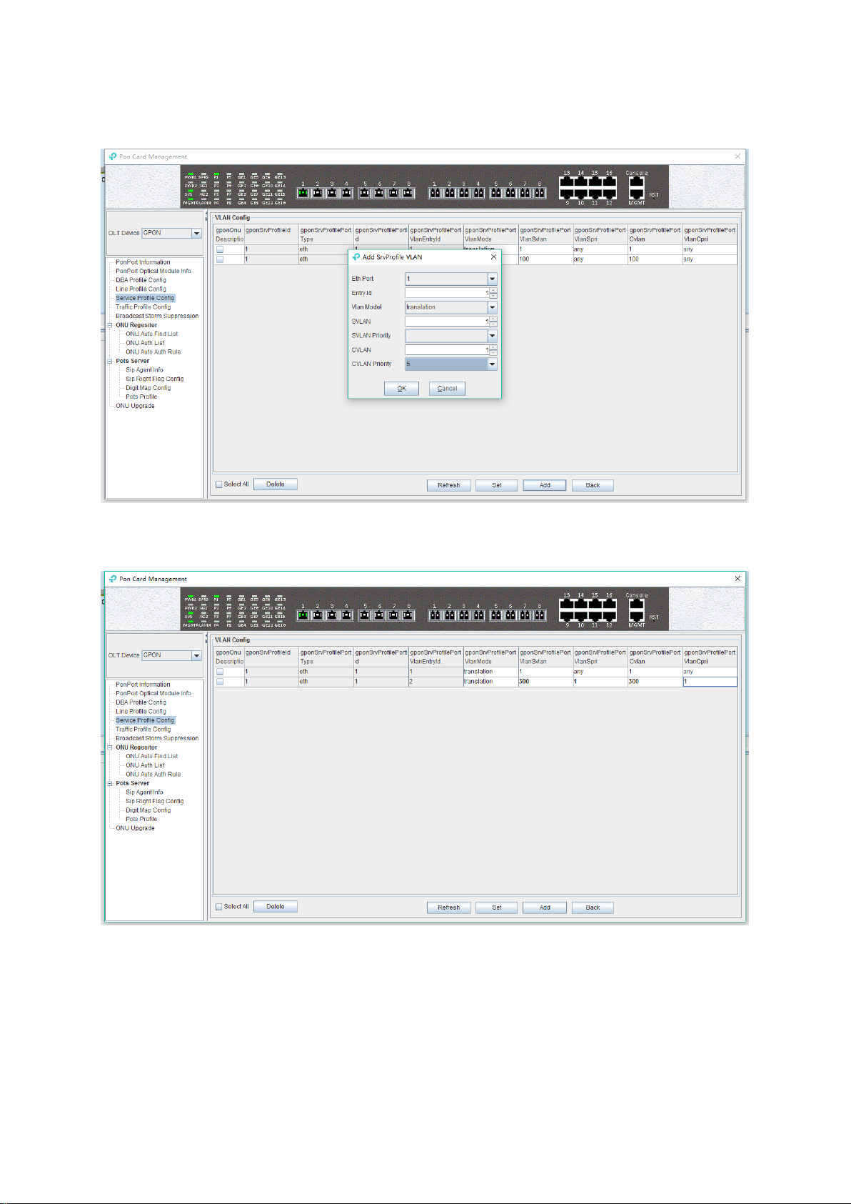
this 3 VLANs, because every time can only add one VLAN, the screenshot below to add a trunk
VLAN 300 to illustrate, SVLAN and CVLAN configuration for the same VLAN 300 which is trunk
VLAN configuration mode:
Step 3:
Return to the 'Vlan Configure' page to view the successful trunk VLAN 300:
6.3.5.2.1.3 ONU Conversion Mode VLAN Configuration
In the main page of the ‘Service Profile’, double-click the 'Configure' button in the 'VLAN'
column of the VLAN service profile you want to configure, and enter the 'Vlan Configure' page.
The specific configuration steps are as follows:
Note: PVID in translation mode needs to be configured in port native – vlan, refer chapter 7.3.2.
Example: configure port VLAN of ONU which converted from 101 to 201,102 to 202, 103 to 203,
70
Page 76
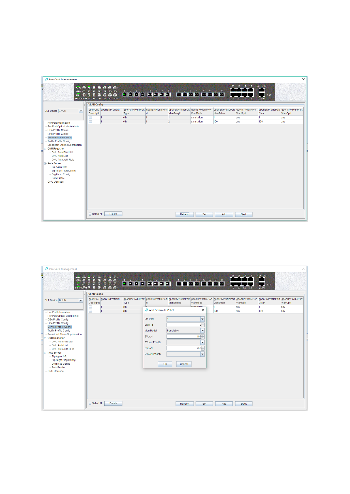
and PVID to 100.
Step 1:
In the 'Vlan Configure' page, select 'translation' of 'vlan mode' and then click 'Set' button to set
the ONU port VLAN to translation mode:
Step 2:
Click ‘Add’ button, add transformation VLAN to the ONU port for 101 to 201,102 to 202,103 to 203,
need three times to add the three transformations, because every time can only add one VLAN to
convert, the following screenshots to configure VLAN is 103 to 203:
71
Page 77

Step 3:
Return to the ‘Vlan Configure’ page to view the VLAN transformation that adds success 103 to
203:
6.3.5.2.1.4 ONU QinQ Mode VLAN Configuration
In the main page of the ‘Service Profile’, double-click the 'Configure' button in the 'VLAN'
column of the service profile you want to configure, and enter the 'Vlan Configure' page. The
specific configuration steps are as follows:
Note: PVID in translation mode needs to be configured in port native – vlan, refer to chapter 7.3.2.
Example: configure the outer VLAN (SVLAN) of QinQ to 1000, the inner VLAN (CVLAN) to 2000,
and PVID to 3000.
Step 1:
72
Page 78

Click 'Add' button, configure ONU port VLAN mode for QinQ, SVLAN for 1000, and CVLAN for
2000:
Step 2:
Return to the 'Vlan Configure' page to view the added SVLAN as 1000, and CVLAN 2000 of
QinQ VLAN:
73
Page 79

6.3.5.2.2 ONU IGMP Configuration In Service Profile
Note: the IGMP service on OLT and ONU currently is passable, and IGMP related configuration is
not work in the present OLT, here is a simple introduction.
In the main page of the service profile, double-click the "Configure" button below the "IGMP"
column of the VLAN, and enter the "IGMP Configure" page:
The following is a description of the configuration of ONU IGMP in service profiles:
Profile Id
Show the service profile id that currently needs to do the multicast configuration.
Multicast Model
The working mode of IGMP is: `igmp-snooping`, `igmp-proxy`, `igmp-snooping-proxy`
(1) igmp - proxy
74
Page 80

Set the IGMP forwarding mode of ONU as proxy.
IGMP proxy is the multicast agent. The IGMP proxy intercept and handling the IGMP message
between the user and the multicast router and then forwards it to the upper multicast router. From
a user perspective, the system is a multicast server equivalent; From an upper point of view, the
system is a multicast user equivalent. The IGMP proxy mode reduces the multicast protocol traffic
of the network side.
(2) igmp snooping
Set the IGMP mode of ONU to IGMP snooping. IGMP snooping is the multicast listening. IGMP
Snooping retrieves the relevant information of maintenance group by listening to the IGMP
message that communicates between the user and the multicast router to maintain items. The
system does not do any processing of the broadcast VLAN message.
(3) igmp snooping - proxy
Igmp-snooping - proxy does not currently apply.
Igmp Forward
The IGMP forwarding mode is not applicable at this moment, the default transparent can be used,
and the VLAN processing mode of the downstream multicast data is handled according to the
single VLAN of the ONU port.
6.3.5.3 Service Profile Modification
In the main page of the 'service profile', the name and the number of ONU ports of the profile can
be directly modified.
Double-click the 'Configure' button below the VLAN or IGMP on the 'Service Profile' main page
to modify parameters such as VLAN and IGMP which the service profile binding. here no longer
illustration. We can know the details by the VLAN and IGMP configuration instructions.
6.3.5.4 Delete Service Profile
In the main page of the service profile, you can select a service profile and then click the 'Delete'
button to delete the entire service profile information:
Note: the service profile can only delete in unbound status, if the service profile is already bound,
the delete operation of the profile will be done after the ONU is deleted or the other service profile
is used.
75
Page 81

6.3.6 OLT Traffic Profile Configuration
The traffic profile on GPON OLT is mainly applied to the ONU port for the port speed limit. Applying
to an ACL for speed limits for a particular message, because we need to create it in advance when
using this profile, a chapter is used to specify some configuration parameters for the profile:
Double click the "PON Module" on the left side of the main page and enter the "Traffic Profile
Configure" page of the "PON Card Management" window. The typical page is as shown below:
Some parameters in the traffic profile configuration are explained below:
Profile id
Show the configured traffic profile id, which can be used later when you need to bind the traffic
profile.
Profile name
76
Page 82

Show the configured traffic profile name, which can be modified when you need to bind the traffic
profile.
ensure information rate (CIR)
To show and modify the guaranteed bandwidth, the effect of bandwidth is to ensure that the traffic
rate can reach its guaranteed bandwidth when the traffic is congested. The default minimum
configuration is 64kbps, and the unit is kpbs.
peak information rate (PIR)
The maximum bandwidth is shown and modified, and the maximum bandwidth is only a limited
effect. The limit of the traffic can not exceed its maximum bandwidth. The default minimum
configuration is 128kbps, and the unit is kpbs.
ensure the burst length (CBS)
Show and modify the guarantee burst length, that is the instantaneous ability to pass the promise
burst traffic, the default minimum configuration is 2000bytes, the unit is byte.
peak burst length (PBS)
Show and modify peak burst length, peak burst size, the default minimum configuration is
2000bytes, the unit is byte.
Bind Num
Show times the traffic profile has been applied.
[Example of traffic profile configuration ]
Example: add a traffic profile which id is 200, name is 'GPON TEST', ensure bandwidth is 20M
and the maximum bandwidth is 100M.
6.3.7 PON Broadcast Storm Suppression
The number of the broadcast network frame increase sharply and affects normal network
communication, broadcast storm will occupy a considerable network bandwidth, cause the entire
network cannot work normally. Broadcast storm control is allowing the port to filter the broadcast
storm that appears on the network. When the broadcast storm control is enabled, the port will
77
Page 83

automatically discard the broadcast frames received when the broadcast frames received from the
port are accumulated to the predetermined threshold value. When the function disabled or
broadcast frames don’t come to limit, the broadcast frames will be broadcast to other ports of OLT.
Double click the 'PON Module' icon on the left side of the main page and enter the 'Broadcast
Storm Suppression' page of the 'PON Card Management' window. The typical page is as shown
below:
Entering this page can set and enable the storm suppression and setting speed of various storm
suppression for OLT's PON.
The following is a description of the storm control parameters of the PON port of OLT.
Port ID
Show the PON index number that needs to be configured for storm suppression.
Unicaststorm Enabled
Enable or disable the unknown unicast storm suppression function of the PON, select 'true' to
enable and 'flase' to disable.
UnicastStorm InPacket Rate
Configure unknown unicast storm suppression rate for PON port, the unit is PPS.
Multicast Storm Enabled
Enable or disable the unknown multicast storm suppression function of the PON, select 'true' to
enable and 'flase' to disable.
MulticastStorm InPacket Rate
Configure multicast storm suppression rate for PON port, the unit is PPS.
Broadcast Storm Enable
Enable or disable the broadcast storm suppression function of the PON, select 'true' to enable and
'flase' to disable.
Broadcast Storm InPacket Rate
78
Page 84

Configure broadcast storm suppression rate for PON port, the unit is PPS.
6.3.8 ONU Auto Authentication
Before GPON authentication, the OLT needs to open the automatic discovery function of the PON,
then find the ONU in the automatic list, and finally add the ONU to authentication.
The authentication steps of GPON is mainly divided into the following parts.
6.3.8.1 Open ONU Auto Discovery and Auth
Double click the 'PON Module' icon on the left side of the main page and enter the 'ONU Auto
Find List' page of the 'PON Card Management' window:
We can do many operations in this page, we can enable the automatic find function of the ONU of
PON, check the automatical but not auth ONU, and verify the ONU of automatic find.
Enables PON automatic find
Turn on the ONU auto find function of the specified PON ports, and only the ONU connected to the
PON will be displayed.
Select the specified PON port, select 'enable' (open) or 'disable' (not open), and then click the
'Set' button.
View the PON's ONU
When the ONU auto find function is opened, you can select a PON port to view which ONU is
found under the PON port.
Select the specified PON port and click the 'Search' button.
Authentication
Auth the ONU which we found on this page.
[Example of enable the ONU automatic find + authentication configuration]
Example: start the ONU automatic authentication of PON1, then add the ONU of the PON1
finding and bind to the created line profile and service profile.
79
Page 85

Step 1:
Enable the automatic find function of PON1 in the ‘ONU Auto Find List’ page:
Step 2:
Find ONU at the ‘Search ONU of those PonPort’:
Step 3:
Select ONU, Click the ‘auth’ button, and select the line and service profile created before:
80
Page 86

6.3.8.2 View Registered ONU And Register ONU Independently
Double click the 'PON Module' icon on the left side of the main page and enter the 'ONU Auth
List' page of the 'PON Card Management' window:
In this page, you can view the ONU information that has been registered and manually add the
authentication ONU, detailed description of some of the more important parameters as follows:
Check the registered ONU
You can query All (All) registered ONU of OLT or registered under specific PON port (pon1-pon8).
The relevant ONU parameter as follows:
Auth Mode
It shows that the registered mode of ONU. GPON is certified by SN. The ONU authentication
mode supported on OLT is: sn, sn + password and password.
ONU Sn
Show the registered ONU's SN in port, the SN of ONU must be the ASCII value of 12 bits.
Password
If ONU is registered by the SN + password or password authentication mode, the ONU
authentication password will be displayed here.
Line Id
Shows which line profile id is binding on the ONU, and double-clicking the id to displays detailed
information about the line profile configuration.
81
Page 87

Service Id
Shows which service profile id is binding on the ONU, and double-clicking the id displays the
details of the service profile configuration.
Run State
The running state can reflect whether the ONU is online or not. The state of ‘online’ state indicates
that ONU has been registered and launched. The ‘offline’ state indicates that the ONU is not
registered, and it is necessary to check whether the light power of the ONU is normal.
Config Statue
The configuration statue can reflect whether OLT send the configuration file to ONU successfully.
The 'failed' status indicates that the default configuration is not recognized by the ONU, which
requires the positioning analysis. ‘success’ shows that the status indicates that the default
configuration of OLT is recognized by the ONU.
Match State
Match statue can reflect the ONU port whether actual ability and binding service profile
configuration of port capacity match, 'match' status show that port number of ONU service profile
configuration is match to ONU actual report; 'mismatch' status show that port number of ONU
service profile configuration is not match to ONU actual report, need to see the actual reported
ONU port number, and then configure the ONU port number in the ONU service profile.
Active Status
The active state indicates whether the ONU is active, and the 'active' indicates that ONU has
82
Page 88

been activated on OLT; 'deactive' means that ONU is not activated on OLT.
add authentication and auth ONU manually
If you know the auth SN or password of ONU in advance, you can register the ONU with the "Add"
button on this page.
active or deactive ONU
In the ‘ONU Auth List’ page, select an ONU to active or deactivate the ONU that has been
registered.
6.3.8.3 Register ONU Automatically
GPON OLT support automatic auth ONU function, if the OLT enable the function of automatic auth
and configured automatic auth rules in advance, ONU can automatically register according to the
configuration.
Double click the "PON Module" on the left side of the main page and enter the ‘ONU Auto Auth
rule" page of the "PON Card Management" window:
83
Page 89

We can configure rules of register ONU function on GPON OLT automatically in this page, and
some parameters will be given to illustrate:
AutoAuth Enable
This option enables or disable the global auto auth ONU function on OLT.
AutoAuth Model
Configure auto auth rules of the ONU on the OLT, we can choose all (all) ONU adopt automatic
auth certification, according to ONU model (equid) automatic auth certification, according to the
ONU manufacturer (vendor) automatic auth certification, according to ONU model (equid) + ONU
software version (swer) automatic auth certification.
PonPort List
Specify which PON port to open ONU automatic auth function.
Port AutoAuth
enable or disable the ONU automatic auth function of a PON.
Add rules of auto auth
The 'add' button on the page can add an auto auth rule.
[Example of ONU automatic registration configuration]
Example: enable the automatic registration function of PON1 on OLT, the automatic registration
rules are based on the ONU model of ONT 1GE, automatic binding line profile: ontline profile_50,
service profile: ontsrvprofile_50.
84
Page 90

6.3.9 ONU VOIP Service Configuration
TP-Link GPON OLT supports configuring ONU SIP, but in the real deployment, some of the ONU
only support SIP configuration through TR-069, and can not be configured by OMCI. In that case,
you should not do the SIP configuration on OLT. The following sections describe the SIP voice
configuration on OLT:
6.3.9.1 SIP Proxy Server Profile Settings
Double click the 'PON Module' icon on the left side of the main page and enter the 'SIP Agent
Info' page of the' PON Card Management 'window:
In this page, user usually need to configure the following parameters. For the other parameters ,
please keep it as default value.
gponSipAgentProfileSignalPort
85
Page 91

Configure the SIP registration server port number on the ONU, default is 5070, can be set
according to your SIP register server configuration.
gponSipAgentProfileProxyServerUrl
Configure the proxy server address on the ONU, which is generally the IP address or domain
name.
gponSipAgentProfileRegistrationServerUrl
Configure the registration server address on the ONU, which is generally the IP address or domain
name.
gponSipAgentProfileVoiceMailServerUrl
Configure the voice mail server address on the ONU, which is generally IP address or domain
name.
gponSipAgentProfileConfFactory
Configure the meeting server address on the ONU, which is generally the IP address or domain
name.
gponSipAgentProfileBindNum
Show times that the SIP Agent profile is bound by ONU.
[Example of SIP proxy server configuration]
Example: create a SIP agent profile with ID 1, with a port number of 5060, and the proxy server
and registration server IP address set to 192.168.5.254
Step 1:
Click the ‘Add’ button to add a SIP proxy server profile:
86
Page 92

Step 2:
Configure the SIP registration port to 5060, the SIP registration server and the proxy server
address to 192.168.5.254:
87
Page 93

6.3.9.2 SIP Extension Business Profile Settings
Double click the 'PON Module' icon on the left side of the main page and enter the 'Sip Right
Flag Configure' page of the 'PON Card Management' window:
In this page, user can enable the call waiting, call transfer, call display and other extension
functions. Click the 'Add' button to add a SIP extension business profile, which is configured as
follows:
88
Page 94

call waiting
Configure the ONU SIP voice call waiting function with both enable and disable options.
call processing
Threeparty: enable or disable the three-way call feature of the ONU SIP voice.
Calltransfer: enable or disable the call transfer function of the ONU SIP voice.
Callhold: open and close the ONU SIP voice call waiting.
Callhold: start and close the ONU SIP voice call ban.
DoNotdisturb: the ability to turn on and close ONU SIP voice.
Conference: open and close the ONU SIP Conference function.
hotline
Hotline: open or close the SIP voice Hotline function of ONU.
HotlineDelay: open or close the SIP voice helpline delay function of ONU
[Example of SIP extension business profile configuration ]
Example: create a SIP extension business profile with id 1 and open the hotline number
88884444.
Step 1:
Click the ‘Add’ button to add a SIP extension business profile:
89
Page 95

Step 2:
The ‘SipRight Flag config’ page can look at the SIP extension business profile that has been
added to it:
90
Page 96

6.3.9.3 Set SIP Number Diagram Profile
Double click the ' PON Module' icon on the left side of the main page and enter the 'Digit Map
config' page of the 'PON Card Management' window:
In this page, you can set the SIP Digit Map profile and dial matching rules for ONU, and the
configuration parameters are as follows:
Critial dial time(s)
Set the timeout time of the exact match rule for the ONU SIP digit map, and the time unit is ‘s’.
Partial dial time(s)
Set the timeout time of the matching rule for the ONU SIP digit map, the time unit is s.
Digitmap format
91
Page 97
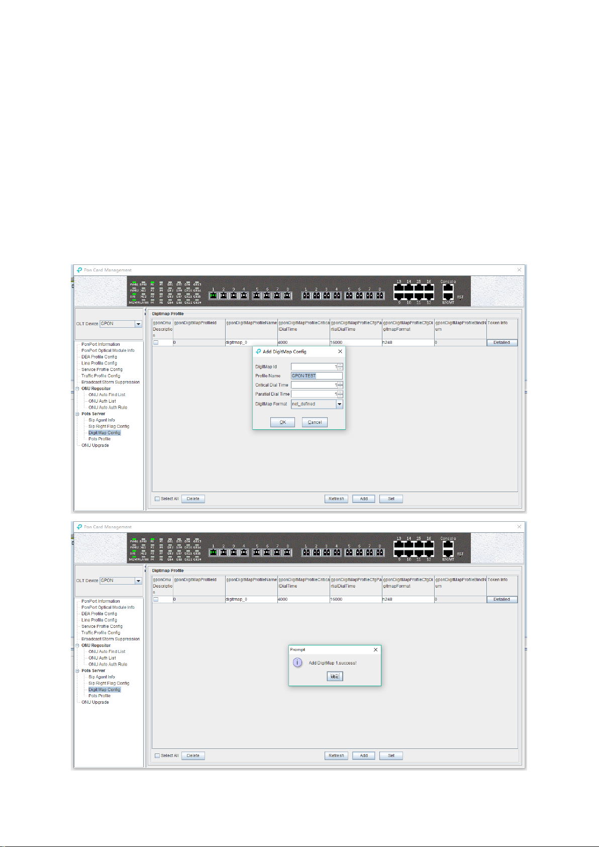
Set the format of the digit map to match the ONU SIP digit map, with notDefined, h248, NCS,
vendorSpecific options.
Bind Num
Show times the SIP map profile is bound by ONU.
Token infor
Configure ONU SIP to match the number of matching rules, double click the ‘Token Infor’ button,
and open the SIP voice dial rule configuration page of ONU.
[Example of SIP digit map profile configuration]
Example: set up a SIP digit map profile with id 1, with a minimum of 8-digit phone Numbers.
Step 1:
Click 'Add' button to add a SIP digiet map profile:
92
Page 98

Step 2:
Double click the 'Add' button of the 'Detailed' button of digit map profile 'Token Infor' that you just
created, and enter the' Dial Plan' configuration page:
Step 3:
On the ‘Dial Plan’ page, click ‘Add’ to add a dial rule to match the 8-digit phone number, and 8 x
can be configured in the matching rule.
93
Page 99

Step 4:
In the ‘Dial Plan’ configuration page, you can view the matching rule of the phone number that
you just created.
94
Page 100

6.3.9.4 Set SIP Post Profile
Double click the ' PON Module' icon on the left side of the main page and enter the 'Post profile'
configuration page of the 'PON Card Management' window:
The main part of this page is to configure some of the hardware related parameters of the ONU
post port, which can be added and adjusted as needed, not detailed in detail.
6.3.10 Upgrade ONU
Double click the ' PON Module' icon on the left side of the main page, open the 'PON Card
Management' window and enter the 'ONU upgrade' page:
The configuration management page can be used in batches or individual upgrades of ONU
software.
Note: before upgrading, you need to ensure that there is an upgrade file. The FTP server can
95
 Loading...