

Page 1
Ar
cher D9
AC19 00 Wi reles s Dual Band Gi gab it ADSL2+ M odem
uter
Ro
R
ev: 1.0.0
1910011060
Page 2

PYRIGHT & TRADEMARKS
CO
pecifications are subject to change without notice.
S
TP-LINK TECHNOLOGIES CO., LTD. Other brands and product names are trademarks or
registered tradem arks of thei r respectiv e holders.
No part of the specifications may be reproduced in any form or by any means or used to make any
derivative such as translation, transformation, or adaptation without permission from TP-LINK
TECHNOLOGIES CO., LTD. Copyright © 2014 TP-LINK TECHNOLOGIES CO., LTD. All rig hts
reserved.
http://www.tp-link.com
i
s a registered trademark of
Page 3

This device is indoor used only.
CC STATE MENT
F
his equipment has been tested and found to comply with the limits for a Class B digital device,
T
pursuant to part 15 of the FCC Rules. These limits are designed to provide reasonable protection
against harmful interference in a residential installation. This equipment generates, uses and can
radiate radio frequency energy and, if not installed and used in accordance with the instructions,
may cause harmful interference to radio communications. However, there is no guarantee that
interference will not occur in a particular installation. If this equipment does cause harmful
interference to radio or television reception, which can be determined by turning the equipment off
and on, the user is encouraged to try to correct the interference by one or more of the following
measures:
• Reorient or reloc ate the receivi ng antenna.
• I ncrease the separation betw een the equi pm ent and receiv er.
• Connect the equipment into an outlet on a circuit different from that to which the receiver
is connected.
• Consult the dealer or an experienced radio/ TV techni cian for help.
This device complies with part 15 of the FCC Rules. Operation is subject to the following two
conditions:
1) This devic e may not cause harmful interference.
2) This device must accept any interference received, including interference that may cause
undesired operation.
Any changes or modifications not expressly approved by the party responsible for compliance
could voi d the user’s authority to operate the equi pm ent.
Note: The manufacturer is not responsible for any radio or TV interference caused by
unauthorized modifications to this equipment. Such modifications could void the user’s authority to
operate the equipm ent.
C RF Radiation Exposure Statement
FC
his equipment complies with FCC RF radiation exposure limits set forth for an uncontrolled
T
environment. This device and its antenna must not be co-located or operating in conjunction with
any other antenna or transm itter.
“To comply with FCC RF exposure compliance requirements, this grant is applicable to only
Mobile Configurations. The antennas used for this transmitter must be installed to provide a
separation distance of at least 20 cm from all persons and must not be co-located or operating in
conjuncti on w i th any other antenna or transmit ter.”
conjuncti on w i th any other antenna or transmit ter. This device is indoor used only.
ion distance of at least 22 cm from all persons and must not be co
at
CE
Ma rk Wa rning
Page 4

Outdoor use limited to 10
mW e.i.r.p. within the band
ing of the 2.4 GHz
band has been ongoing in recent years to allow current
If used out si de of own pre m ises, general aut hor ization is
r network and service
This s ubsection do es not apply for the geograph ic al area
This is a class B product. In a domestic environment, this product may cause radio interference, in
w hic h case the user may be required to take adequate m eas ures.
National Restrict ions
This device is intended for home and office use in all EU countries (and other countries following
the EU directi ve 1999/5/E C) w i thout any lim itati on except for the countries m enti oned below :
Country Restriction Reason/remark
Bulgaria None
France
2454-2483.5 M Hz
Italy None
Luxembourg None
Norway Implemented
Russian Federat ion None Only for indoor applicat ions
Gener al aut hor izat ion required for outdoor use and
public serv ice
Military Radiolocation use. Refarm
relaxed regulation. Full implement ation planned 2012
required
General authorization required fo
supply( not f or spectrum)
within a radius of 20 k m from the centre of Ny-Ålesund
Note: Please don’t use the product outdoors in France.
Canadian Compliance Statement
This device complies with Industry Canada license-exempt RSS standard(s). Operation is subject
to the following two conditions:
(1)This device m ay not cause interference, and
(2)This device must accept any interference, including interference that may cause undesired
operation of the devi ce.
Cet appareil est conforme aux norms CNR exemptes de licence d’Industrie Canada. Le
fonctionnem ent es t soum is aux deux conditions sui vantes:
(1)cet appareil ne doit pas provoquer d’interférences et
(2)cet appareil doit accepter toute interférence, y compris celles susceptibles de provoquer un
fonctionnem ent non s ouhaité de l’ appareil.
This device has been designed to operate with the antennas listed below, and having a maximum
gain of 5 dBi. Antennas not included in this list or having a gain greater than 5 dBi are strictly
prohibited for use with this device. The required antenna i mpedanc e is 50 ohms.
To reduce potential radio interference to other users, the antenna type and its gain should be so
chosen that the equivalent isotropically radiated power (e.i.r.p.) is not more than that permitted for
success ful com m uni cation.
Page 5

Industry Canada Stat ement
Com pli es wit h the Canadian I CE S-003 Class B specifications.
Cet appareil numéri que de la classe B est conform e à la norme NM B -003 du Canada.
This device complies with RSS 210 of Industry Canada. This Class B device meets all the
requirem ents of the Canadian interference-causi ng equipm ent regulati ons.
Cet appareil numérique de la Classe B respecte toutes les exigences du Règlement sur le
mat ériel brouilleur du Canada.
Korea Warning St at ements:
당해 무선설비는 운용중 전파혼신 가능성이 있음.
NCC Not ice& BSM I Notice :
注意!
依據 低功率電波輻射性電機管理辦法
第十二條 經型式認證合格之低功率射頻電機,非經許可,公司、商號或使用者均不得擅自變更頻率、
加大功率或變更原設計之特性或功能。
第十四條 低功率射頻電機之使用不得影響飛航安全及干擾合法通行;經發現有干擾現象時,應立即
停用,並改善至無干擾時方得繼續使用。前項合法通信,指依電信規定作業之無線電信。低功率射
頻電機需忍受合法通信或工業、科學以及醫療用電波輻射性電機設備之干擾。
減少電磁波影響,請妥適使用。
安全諮詢及注意事項
●請使用原裝電源供應器或只能按照本產品注明的電源類型使用本產品。
●清潔本產品之前請先拔掉電源線。請勿使用液體、噴霧清潔劑或濕布進行清潔。
●注意防潮,請勿將水或其他液體潑灑到本產品上。
●插槽與開口供通風使用,以確保本產品的操作可靠並防止過熱,請勿堵塞或覆蓋開口。
●請勿將本產品置放於靠近熱源的地方。除非有正常的通風,否則不可放在密閉位置中。
●請不要私自打開機殼,不要嘗試自行維修本產品,請由授權的專業人士進行此項工作。
Продукт сертифіковано згідно с правилами системи УкрСЕПРО на відповідність вимогам
нормативних документів та вимогам, що передбачені чинними законодавчими актами
України.
Page 6

Safety Information
When product has power button, the power button is one of the way to shut off the product;
when there is no power button, the only way to completely shut off power is to disconnect the
product or the pow er adapter from the power source.
Don’t disassemble the product, or make repairs yourself. You run the risk of electric shock
and voiding the lim it ed w arranty. If you need service, please c ontact us.
Avoid water and wet locations.
This product can be used in the follow ing countries:
AT BG BY CA CZ DE DK EE
ES FI FR GB GR HU IE IT
LT LV MT NL NO PL PT RO
RU SE SK TR UA US
Page 7

TP-LINK TECHNOLOGIES CO., LTD
DECLARATION OF CONFORMITY
For the following equipm ent:
Product D escripti on: AC1900 Wireless Dual Band Gigabit ADSL2+ Modem Router
Model No.: Arche r D9
Trademark: TP-LINK
We declare under our own responsibility that the above products satisfy all the technical
regulations appl icabl e to the product within the scope of Council Direc tives:
Directives 1999/5/EC, Directives 2004/108/EC, Directives 2006/95/EC, Directives 1999/519/EC,
Directi ves 201 1/65/ EU
The above product is in conformity with the following standards or other normative documents
EN 300 328 V1.8.1: 2012
EN 301 489-1 V1.9.2:2011& EN 301 489-17 V2.2.1:2012
EN 55022:2010
EN 55024:2010
EN 61000-3-2:2006+A1:2009+A2:2009
EN 61000-3-3:2008
EN 60950-1:2006+A11: 2009+A1:2010+A12:2011
EN 50385:2002
EN 301 893 v1.7.1: 2012
The product carries the CE Mark:
Person responsibl e for m aking this declaration:
Yang Hongliang
Product M anager of International B usines s
Date of issue: 2014
TP-LINK TECHNOLO GIES CO ., LTD
Building 24 (floors 1, 3, 4, 5), and 28 (floors 1-4) Central Science and Technology Park,
Shennan Rd, Nanshan, Shenzhen, China
Page 8

CONTENTS
Package Contents ................................................................................................................ 1
Chapter 1. Product Over vi ew ............................................................................................ 2
1.1 Overview of the Modem Router ........................................................................................2
1.2 Main Features....................................................................................................................3
1.3 Panel Layout......................................................................................................................4
1.3.1 The Fr ont Panel ...........................................................................................................4
1.3.2 The Bac k Panel ...........................................................................................................6
Chapter 2. Connecting the M ode m Route r .................................................................... 8
2.1 System Requirement s .......................................................................................................8
2.2 Installation Environment Requirements ............................................................................8
2.3 Connecting the Modem Router .........................................................................................8
Chapter 3. Quick Installation Guide............................................................................... 10
3.1 TCP/IP Configuration ......................................................................................................10
3.2 Quick Installation Guide ..................................................................................................11
Chapter 4. Confi gur ing the M ode m Route r ................................................................. 15
4.1 Login ................................................................................................................................15
4.2 Status...............................................................................................................................16
4.3 Quick Setup .....................................................................................................................18
4.4 O peration Mode ...............................................................................................................18
4.5 Network............................................................................................................................18
4.5.1 WA N S et tings ............................................................................................................ 19
4.5.2 Interfac e Grouping ..................................................................................................... 28
4.5.3 LAN Set tings ............................................................................................................. 29
4.5.4 IPv6 LA N S et tings ...................................................................................................... 30
4.5.5 MAC Clone ................................................................................................................ 32
4.5.6 ALG Sett ings ............................................................................................................. 32
4.5.7 DSL Set tings ............................................................................................................. 33
4.5.8 IPSec VPN ................................................................................................................ 33
4.6 IPTV .................................................................................................................................36
4.7 DHCP Serv er ...................................................................................................................37
4.7.1 DHCP S ett ings .......................................................................................................... 37
Page 9

4.7.2 Clients List ................................................................................................................. 39
4.7.3 Addr ess Res ervat ion .................................................................................................. 39
4.7.4 Conditional Pool......................................................................................................... 40
4.8 Wireless 2.4GHz..............................................................................................................42
4.8.1 Basi c S et tings............................................................................................................ 42
4.8.2 WP S Set t i ngs ............................................................................................................ 44
4.8.3 Wirel ess S ecurity ....................................................................................................... 46
4.8.4 Wirel ess S chedule ..................................................................................................... 48
4.8.5 Wireless MA C Filtering ............................................................................................... 49
4.8.6 Wirel ess A dvanc ed .................................................................................................... 50
4.8.7 Wirel ess S tat us.......................................................................................................... 52
4.9 Wireless 5GHz.................................................................................................................52
4.9.1 Basi c S et tings............................................................................................................ 52
4.9.2 WP S Set t i ngs ............................................................................................................ 54
4.9.3 Wirel ess S ecurity ....................................................................................................... 56
4.9.4 Wirel ess S chedule ..................................................................................................... 58
4.9.5 Wireless MA C Filtering ............................................................................................... 59
4.9.6 Wirel ess A dvanc ed .................................................................................................... 61
4.9.7 Wirel ess S tat us.......................................................................................................... 62
4.10 Guest Network .................................................................................................................63
4.10.1 Basic Sett i ngs 2.4GHz .............................................................................................. 63
4.10.2 Basic Sett i ngs 5G Hz ................................................................................................. 64
4.10.3 Guest S t atus 2.4GHz ................................................................................................ 66
4.10.4 Guest S t atus 5GHz ................................................................................................... 66
4.11 USB Settings ...................................................................................................................67
4.11.1 USB Mass S torage ................................................................................................... 67
4.11.2 User A cc ount s .......................................................................................................... 68
4.11.3 St orage S hari ng........................................................................................................ 68
4.11.4 FTP Server............................................................................................................... 70
4.11.5 Media Se rver ............................................................................................................ 72
4.11.6 Print S erver .............................................................................................................. 73
4.12 Route Settings .................................................................................................................73
4.12.1 Default Gat eway ....................................................................................................... 74
4.12.2 St atic Route ............................................................................................................. 74
4.12.3 RIP Set tings ............................................................................................................. 75
4.13 IPv6 Route Settings.........................................................................................................75
Page 10

4.13.1 IP v6 Def aul t Gateway ............................................................................................... 75
4.13.2 IP v6 S tati c Rout e ...................................................................................................... 76
4.14 Forwarding .......................................................................................................................77
4.14.1 Vi rt ual S erver ........................................................................................................... 77
4.14.2 Port T riggering.......................................................................................................... 79
4.14.3 DMZ ........................................................................................................................ 81
4.14.4 UPnP ....................................................................................................................... 81
4.15 Parental Control...............................................................................................................82
4.16 Firewall ............................................................................................................................84
4.16.1 Rule ......................................................................................................................... 84
4.16.2 LAN H ost ................................................................................................................. 85
4.16.3 W AN Host ................................................................................................................ 86
4.16.4 Schedule.................................................................................................................. 87
4.17 IPv6 Firewall ....................................................................................................................89
4.17.1 IP v6 Rule ................................................................................................................. 89
4.17.2 IP v6 LA N Hos t .......................................................................................................... 90
4.17.3 IPv6 WA N Ho st ........................................................................................................ 91
4.17.4 IP v6 S chedule .......................................................................................................... 92
4.18 IPv6 Tunnel......................................................................................................................93
4.19 Bandwidth Control ...........................................................................................................96
4.20 IP&MA C Binding ..............................................................................................................97
4.20.1 Bi ndi ng S et tings........................................................................................................ 97
4.20.2 ARP List................................................................................................................... 98
4.21 Dynamic DNS ..................................................................................................................99
4.22 Diagnostic ........................................................................................................................99
4.23 System Tools .................................................................................................................100
4.23.1 Sys t em Log ............................................................................................................ 100
4.23.2 Tim e S ett i ngs ......................................................................................................... 101
4.23.3 Mana ge Cont rol ...................................................................................................... 102
4.23.4 CWM P Sett i ngs ...................................................................................................... 103
4.23.5 SNMP Sett i ngs ....................................................................................................... 104
4.23.6 Back up & Restore................................................................................................... 105
4.23.7 Fac t ory De faults ..................................................................................................... 105
4.23.8 Firm war e Upgrade .................................................................................................. 106
4.23.9 Reboot ................................................................................................................... 107
4.23.10 Statistics ............................................................................................................. 107
Page 11

4.24 Logout ............................................................................................................................109
Appe ndi x A: Specif ications ........................................................................................... 110
Appe ndi x B: Troubl e shoot ing ....................................................................................... 111
Appendix C: Technical Support ................................................................................... 114
Page 12

Archer D9
A C1900 Wireless Dual Band Gigabit A DS L 2+ Modem Router User Guide
Package Contents
The following contents should be found in your package:
One Archer D9 AC1900 Wireless Dual Band Gigabit ADSL2+ Modem Router
One Power Adapter for Archer D9 AC1900 Wireless Dual Band Gigabit ADSL2+ Modem
Router
Quick Installation Guide
One RJ 45 cable
Two RJ11 cables
One ADS L splitter
One Resource CD for Archer D9 AC1900 Wireless Dual Band Gigabit ADSL2+ Modem
Router, inc luding:
• This User Guide
• Other H el pful Inform ati on
Note:
Make sure that the package contains the above items. If any of the listed items are damaged or
mi ssi ng, please contact your distributor.
1
Page 13

Archer D9
A C1900 Wireless Dual Band Gigabit A DS L 2+ Modem Router User Guide
Chapter 1. Produ ct Ov erv iew
Thank you for choosing the Archer D9 AC1900 Wireless Dual Band Gigabit ADSL2+ Mode m
Router.
1.1 Overview of the Modem R outer
The Archer D9 AC1900 Wireless Dual Band Gigabit ADSL2+ Modem Router integrates 4-port
Switch, Firewall, NAT-Router and Wireless AP. The AC1900 Wireless Dual Band Gigabit ADSL2+
Modem Router delivers exceptional range and speed, which can fully meet the need of Small
Office/Home Office (SOHO) networks and the users demandi ng higher networki ng perform ance.
The Archer D9 AC1900 Wireless Dual Band Gigabit ADSL2+ Modem Router utilizes integrated
ADSL2+ transceiver and high speed MIPS CPU. The Router supports full-rate ADSL2+
connectiv ity c onform ing to the ITU and ANSI specifications.
In addition to the basic DMT physical layer functions, the ADSL2+ PHY supports dual latency
ADS L2+ fram ing (fast and interleaved) and the I .432 ATM P hysi cal Layer.
The modem router provides up to 600Mbps ( 2. 4G Hz) + 1300Mbps (5GHz) wireless connection with
other wireless clients. The incredible speed makes it ideal for handling multiple data streams at the
same time, which ensures your network stable and smooth. The performance of this 802.11ac
wireless modem router w ill give you the unexpected networking experience at speed much faster than
802.11n. It is also compa tible w ith all IEEE 802.11a, IEEE 802.11b, IEEE 802.11g and IEEE 802.11n,
products.
With multiple protection measures, including SSID broadcast control and wireless LAN 64/128
WEP encryption, Wi-Fi protected Access (WPA2-PSK, WPA-PSK), as well as advanced Firewall
protections, the Archer D9 AC1900 Wireless Dual Band Gigabit ADSL2+ Modem Router provides
com plete data privacy.
The modem router provides flexible access control, so that parents or network administrators can
establish restricted access policies for children or staffs. It also supports Virtual Server and DMZ
host for Port Triggering, and then the network administrators can manage and monitor the network
in real time with the remote m anagem ent function.
Since the modem router is compatible with virtually all the major operating systems, it is very easy
to manage. Quick Setup Wizard is supported and detailed instructions are provided step by step in
this user guide. Before installing the modem r outer , please look through this guide to know all the
modem r outer’s func tions.
2
Page 14

Archer D9
A C1900 Wireless Dual Band Gigabit A DS L 2+ Modem Router User Guide
1.2 Main Features
Supports IEEE 802.11 ac.
Supports simultaneous 2.4GHz 600Mbps and 5GHz 1300Mbps connections for 1.9Gbps of
total avai lable bandw idth.
Four 10/100/1000Mbps Auto-N egotiati on RJ45 LAN ports (Auto M DI /M D I X), one RJ 11 port.
P rovides a U SB 3.0 port and a US B 2.0 port supporti ng file s haring and print server.
P rovides external splitt er.
A dopts A dvanced DMT modulati on and demodulation t echnology.
S upports bridge m ode and Router function.
Multi-user sharing a high-speed I nternet connec tion.
Downstream data rates up to 24Mbps, upstream data rates up to 1Mbps .
S upports long trans fers, the m ax line length can reach to 6.5K m.
S upports rem ote confi guration and m anagem ent through S N M P and CWM P .
Supports PPPoE, which allows connecting to the Internet on demand and disconnecting from
the Internet when idle.
P rovides rel iable E S D and surge-protect functi on w i th quick response sem i-conducti ve surge
protection ci rcuit.
High speed and asy m metrical data transmit mode, provides safe and exclusive bandwidth.
Compatible with all mainstreams DSLAM (CO).
P rovides i ntegrated acces s of internet and route function w hi ch face to SOHO user.
Real-time Configuration and dev ice m oni toring.
S upports M ulti ple PVC (Perm anent V irtual C ircui t).
Built-in DHCP server.
Built-in firewal l, supporting I P /M AC filter and U R L filter.
S upports V irtual Server, DM Z host and Port Triggering.
S upports Dy nam ic DN S, U PnP and Static Routing.
S upports sys tem log and flow Statistics.
S upports firm ware upgrade and Web m anagem ent.
P rovides W P A-PSK/WPA2-PS K data security, TKI P /A ES encryption s ecurity.
P rovides 64/ 128-bit WE P encryption securi ty and w i reless LAN ACL (Access Control List).
S upports E thernet WA N (EWA N ).
Supports Bandw i dth Control.
S upports I P v6.
S upports Guest Netw ork.
3
Page 15
Archer D9
A C1900 Wireless Dual Band Gigabit A DS L 2+ Modem Router User Guide
1.3 Panel Layout
is connected
1.3.1 The Front Panel
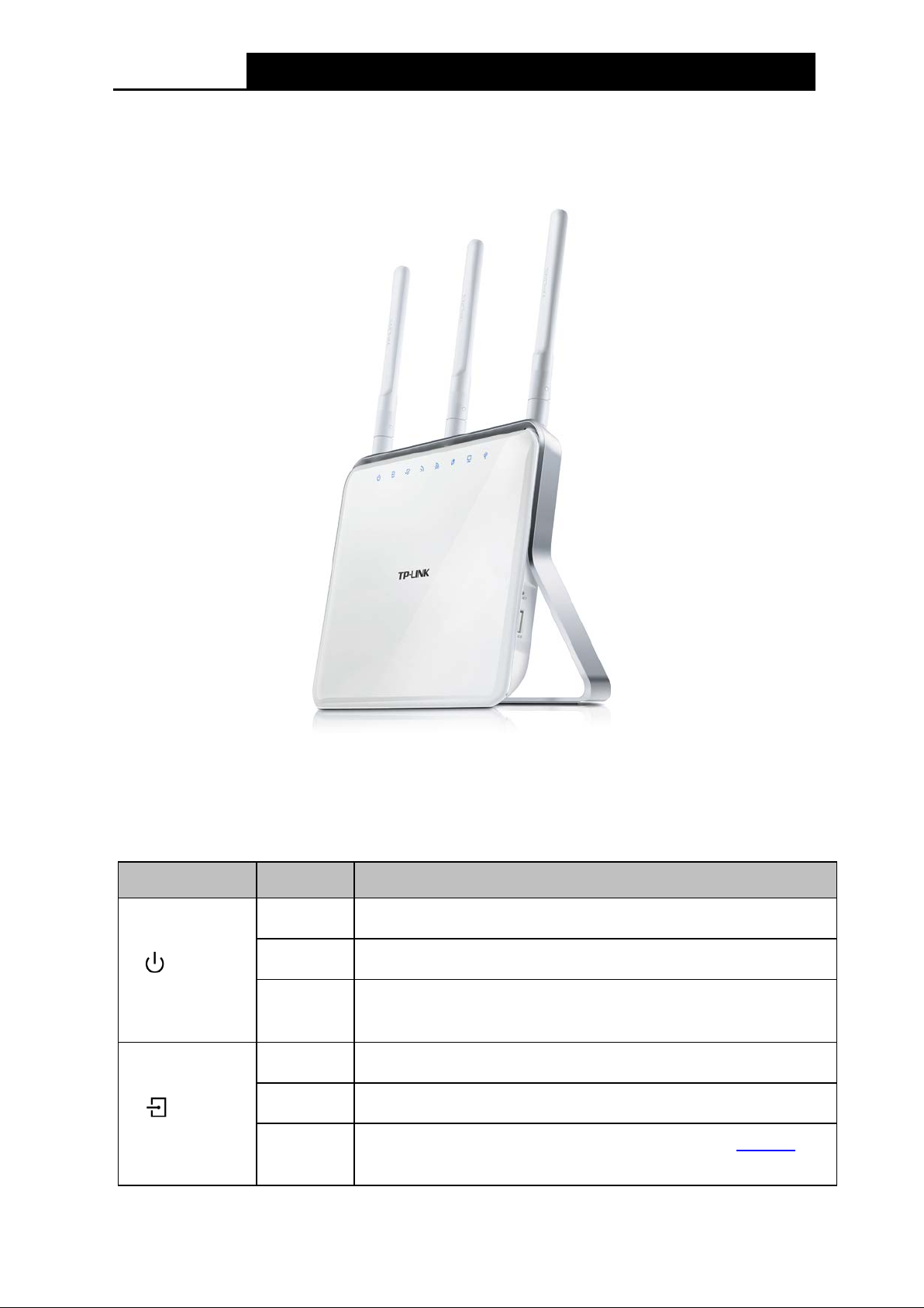
Figure 1-1
The modem router’s LED s are located on the top panel (View fr om top to bottom). They i ndicate
the device’ s worki ng status. For details, pl ease refer to LED Explanation.
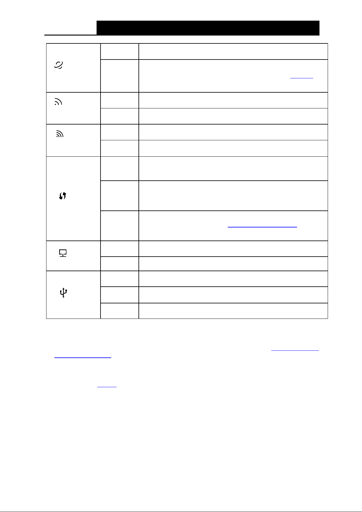
LED Explanation:
Name Status Indication
On
Flashing
(Power)
Off
On
Flashing
(ADSL)
Off
System start-up compl ete.
Sys tem starting up or device updating.
Power is off. Please ensure that the power adapter
correctly.
ADSL line is synchronized and ready to use.
The ADS L negotiation is i n progress.
ADSL synchronization fails. Please refer to Note 1
troubleshooting.
for
4
Page 16
Archer D9
A C1900 Wireless Dual Band Gigabit A DS L 2+ Modem Router User Guide
There is no successful Internet connection or the modem router
A wireless device has been successfully added to the network by
button on other wireless devices
A wireless device has failed to be added to the network by WPS
for more
(Internet)
(Wireless
2.4GHz)
(Wireless
5GHz)
(WPS)
On
Off
On
Off
On
Off
On
Flashing
Off
The netw ork is availabl e w i th a successful Internet connection.
is operating in Bridge mode. Please refer to Note 2 for
troubleshooting.
The w ireless 2.4GHz band is working properly.
The 2.4GHz wireless function is disabled.
The w ireless 5GHz band is wor k ing properly.
The 5GH z w i reless function is disabled.
WPS function.
WPS handshaking is in process and will continue for about 2
minutes. Please press the WPS
that you want to add to the network while the LED is flashing.
function. Please refer to 4.8.2 WPS Settings
information.
On
(LAN)
Off No LAN port is connected.
On
(USB)
Note:
1. If the ADSL LED is off, please check your Internet connection first. Refer to 2 .3 C onne c t ing
the Modem Router for more information about how to make Internet connection correctly. If
you have already made a right connection, please contact your ISP to make sure your Internet
service is availabl e now .
2. If the Internet LED is off, please check your ADSL LED first. If your ADSL LED is also off,
please refer to Note 1
may need to check this par t of information with your ISP and make sure everything have been
input correctl y.
Flashing
Off
. If your ADSL LED is ON, please check your Internet configuration. You
At least one LAN port is connected.
At least one USB por t is connected.
The USB port is sending or receivi ng data.
No USB port is connected.
5
Page 17
Archer D9
A C1900 Wireless Dual Band Gigabit A DS L 2+ Modem Router User Guide
1.3.2 The Back Panel
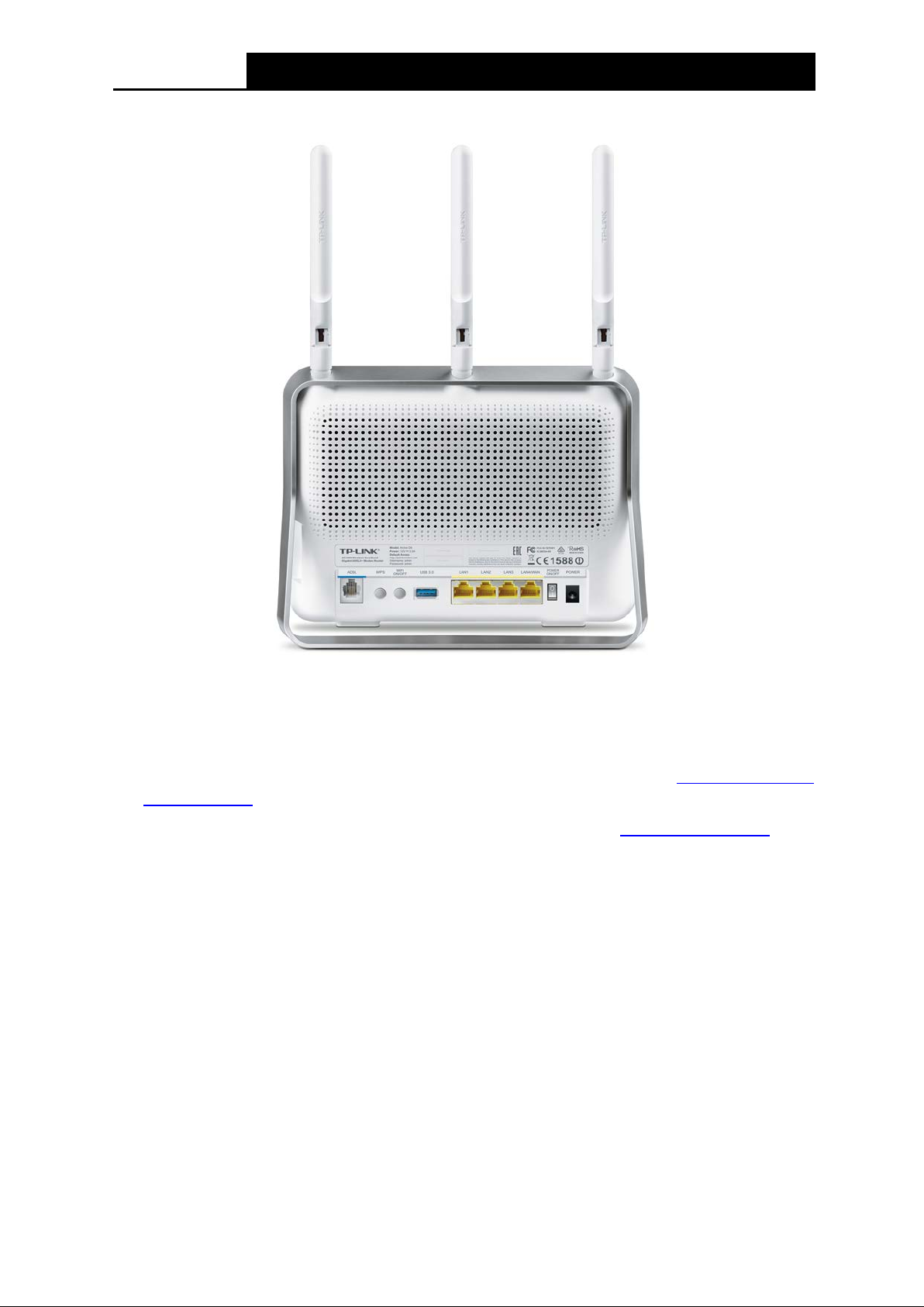
Figure 1-2
The following parts are located on the rear panel (View from left to right).
ADSL: Through the port, you can connect the telephone to the modem router. Or yo u ca n
connect them by an external separate splitter. For details, please refer to
Modem Router.
WPS: The sw i tch for the WPS function. For details, pleas e refer to 4.8.2 WPS Settings.
WiFi ON/OFF: The swi tch for the WiFi func tion. Press it to enable/disable t he WiFi function.
USB 3.0: The US B 3.0 port connects to a US B 3.0 storage devi ce or a US B 3.0 printer.
LAN1, LAN2, LAN3, LAN4/WAN: Through these ports, you can connect the modem router to
your PC or other Ethernet network devices. In wireless router mode you will be able to
connect to Cable/FTTH/VDSL/ADSL devices.
POWER ON/OFF: The swi tch for the pow er.
POWER: The Power plug is where you will connect the power adapter.
Antennas: Used for w ireles s operation and data transmi t.
The following parts are located on the side panel (View from top to bottom).
2.3 Connecting the
USB 2.0: The US B 2.0 port connects to a U S B 2.0 storage dev ice or a US B 2.0 printer.
RESET: There are tw o ways to reset the modem router's factory defaults.
6
Page 18

Archer D9
A C1900 Wireless Dual Band Gigabit A DS L 2+ Modem Router User Guide
Me t ho d one : With the modem router powered on, use a pin to press and hold the RESET
button for at least 8-10 seconds. And the modem router will reboot to its factory default
settings.
Method two : Restore the default setting from 4.23.7 Factory Defaults of the modem router's
Web-based Management.
7
Page 19

Archer D9
A C1900 Wireless Dual Band Gigabit A DS L 2+ Modem Router User Guide
:
Chapter 2. Connecting the Modem Router
2.1 System R equireme nts
Broadband Internet A cces s Service (DS L/Cabl e/Et hernet).
PCs wi t h a worki ng Ethernet Adapter and an Ethernet cable w i th RJ45 connectors.
TCP/ I P protocol on each P C.
Web browser, such as Microsoft Internet Explorer, Mozilla F irefox and Apple Safari.
2.2 Inst allat ion Environm ent Requirement s
The Produc t should not be located w here it w i ll be ex posed to moi sture or exces sive heat.
Place the modem router in a location where it can be connected to the various devices as well
as to a power source.
Make sure the cables and power cord are safely placed out of the way so they do not cr eate a
tripping hazard.
The modem router can be placed on a shelf or desktop.
Keep away from the strong electromagnetic radiation and the device of electromagnetic
sensitive.
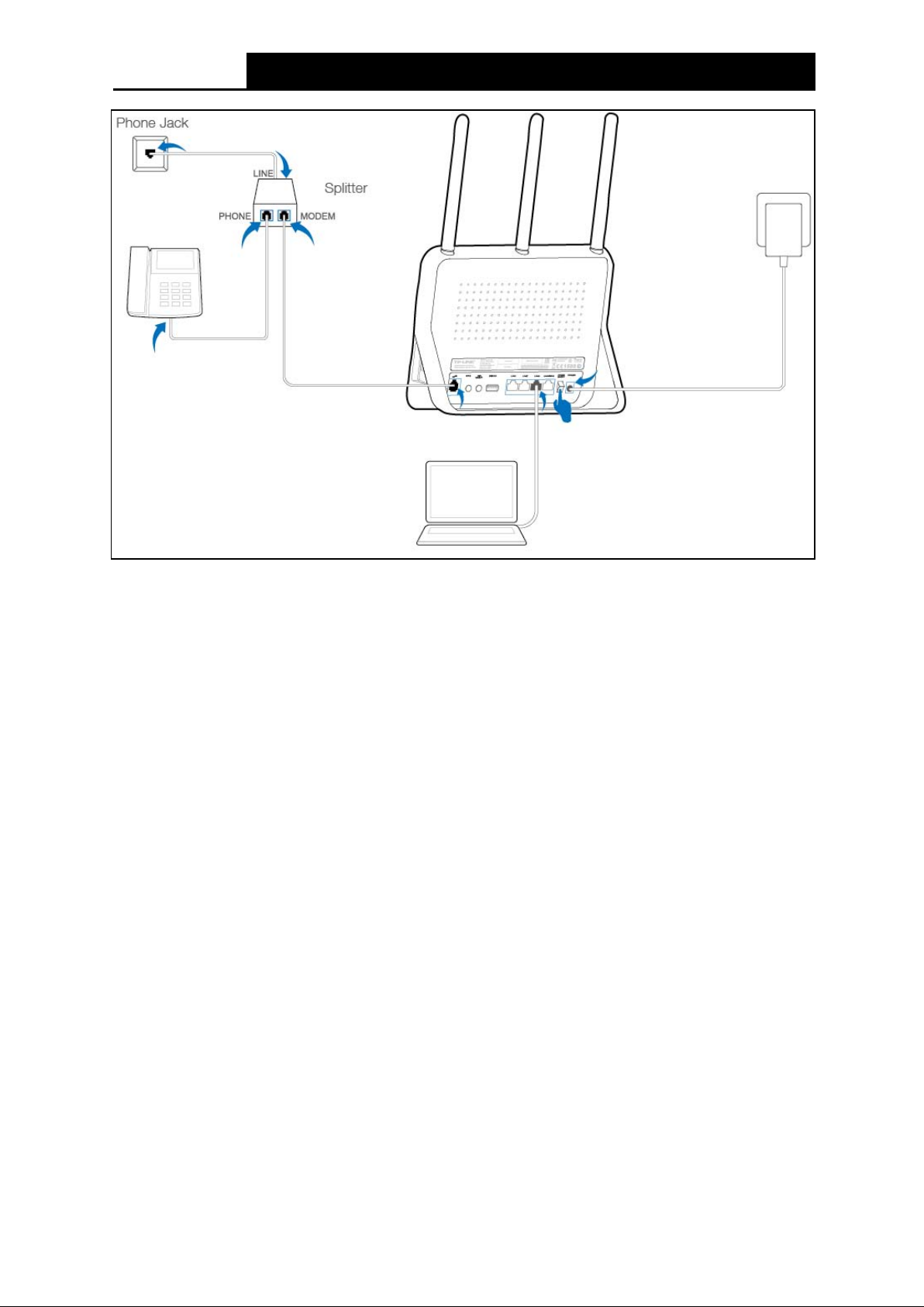
2.3 Connecting the Modem Router
Before installing the device, please make sure your broadband service provided by your ISP is
available. If there is any problem, please contact your ISP. Before cable connection, cut off the
pow er supply and keep your hands dry. Y ou can follow the steps bel ow to install it.
Step 1: Connect the A DS L Line.
Meth od on e: Pl ug one end of the twi sted-pair ADSL cable into the ADSL port on the rear
panel of Archer D9, and insert the other end into the Phone Jack.
Method two
voice, and then you can access the Internet and make calls at the same time. The
ex ternal splitter has three ports:
• LINE: Connect to the P hone J ack
• PHONE: Connect to the phone sets
• MODEM: Connect to the ADSL port of Archer D9
Plug one end of the twisted-pair ADSL cable into the ADSL port on the rear panel of
Archer D9. Connect the other end to the MOD EM port of the external spli tter.
Step 2: Connect the Ethernet cable. Attach one end of a network cable to your computer’s
Ethernet port or a regular hub/switch port, and the other end to the LAN port on the
modem r outer Archer D9.
Step 3: Pow er on the comput ers and LAN devices.
Step 4: Attach the power adapter. Connect the power adapter to the power connector on the rear
of the device and plug in the adapter to an electrical outlet or power extension. The
electric al outlet shall be instal led near the device and shall be easil y accessible.
You can use a separate splitter. External splitter can divide the data and
8
Page 20
Archer D9
A C1900 Wireless Dual Band Gigabit A DS L 2+ Modem Router User Guide
Figure 2-1
9
Page 21
Archer D9
A C1900 Wireless Dual Band Gigabit A DS L 2+ Modem Router User Guide
Chapter 3. Quick Installation G uid e
This chapter will show you ho w to configure the basic functions of your Archer D9 AC1900
Wirel ess Dual Band Gigabit A DS L2+ Modem Router using Quick Setup Wizard w i thin m inut es.
3.1 TCP/IP Configuration
The default IP address of the Arch er D 9 AC1900 Wireless Dual Band Gigabit ADSL2+ Modem
Router is 192.168.1.1. And the default Subnet Mask is 255.255.255.0. These values can be
changed as you desire. In this guide, we use all the default val ues for description.
Connect the local PC to the LAN/WAN port of the modem router. And then you can configure your
PC in the following way.
1) Set up the TCP/IP Protocol in "Obtain an IP address automatically" mode on your PC.
If you need instructions as to how to do this, please refer to T3 in
Troubleshooting.
2) Then the built-in DHCP server w i ll assign IP address for the PC.
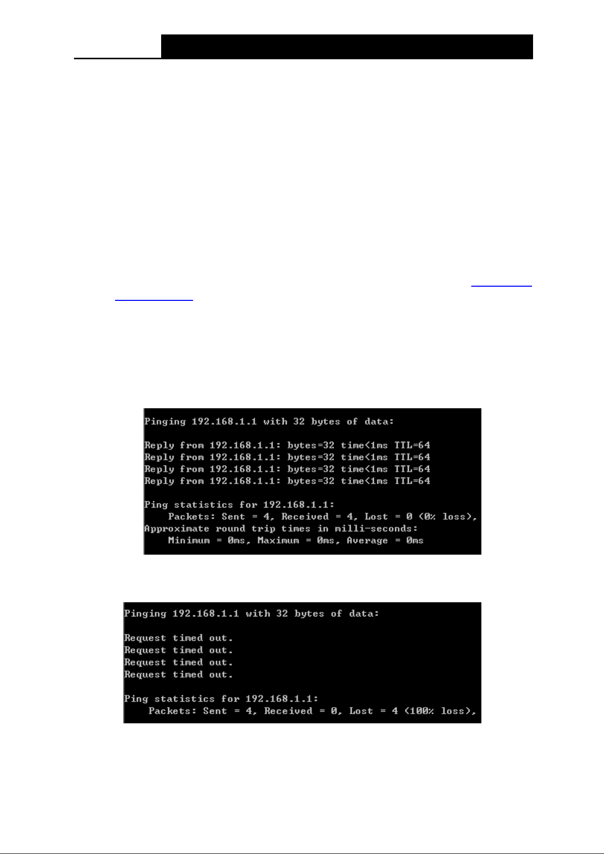
No w, you can run the Ping command in the command prompt to verify the network connection.
Please c lick the Start menu on your desktop, select run tab, type cmd or command in th e field
and press Enter. Type p ing 192.168.1.1 on the nex t screen, and then press Enter.
Appendix B:
If the result displayed is similar to the screen below, the connection between your PC and the
router has been establi shed.
If the result displayed is similar to the screen shown below, it means that your PC has not
connected to the router.
You can check it following the steps below :
1) Is the connection be twee n y our P C a nd the router correct?
10
Page 22
Archer D9
A C1900 Wireless Dual Band Gigabit A DS L 2+ Modem Router User Guide
The LEDs of LAN port which you link to the device and the LEDs on your PC's adapter should
be lit.
2) Is the T CP / IP confi guratio n for your PC c orrect?
If the router's IP address is 192.168.1.1, your PC's IP address must be within the range of
192.168.1.2 ~ 192.168.1. 254.
3.2 Quick Installation Guide
With a Web-based utility, it is easy to configure and manage the Archer D9 AC1900 Wireless Dual
Band Gigabit ADSL2+ Modem Router. The Web-based utility can be used on any Windows,
Macintosh or UNIX OS with a Web browser, such as Microsoft Internet Explorer, Mozilla Firefox or
Apple Safari.
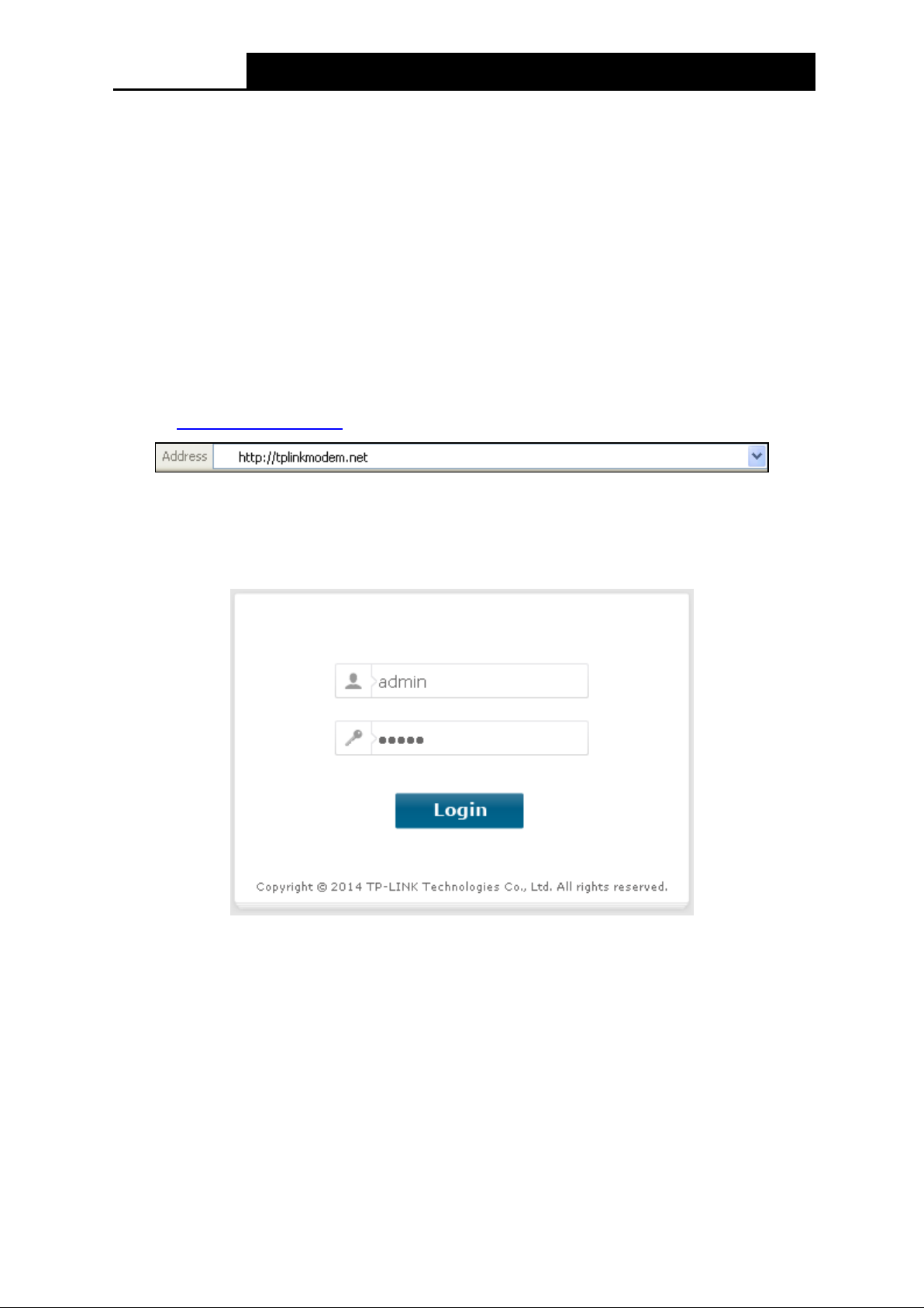
Step 1. To access the configuration utility, open a web-browser and type the default address
http://tplinkmodem.net/
After a moment, a login window will appear, similar to the Figure 3-2. Enter admin for the
User Name and Password, both in lower case letters. Then click the Login button or
press the Enter key.
in the address fiel d of the browser.
Figure 3-1
Figure 3-2
Note:
1) Do not mi x up the user name and password with your ADSL account user name and password
which are needed for PP P connections .
2) If the above screen does not pop up, it means that your Web-browser has been set to a pr oxy.
Go to Tools menu→Internet Options→Connections→LAN Settings, in the screen that
appears, cancel the U si ng Prox y checkbox , and click OK to finish it.
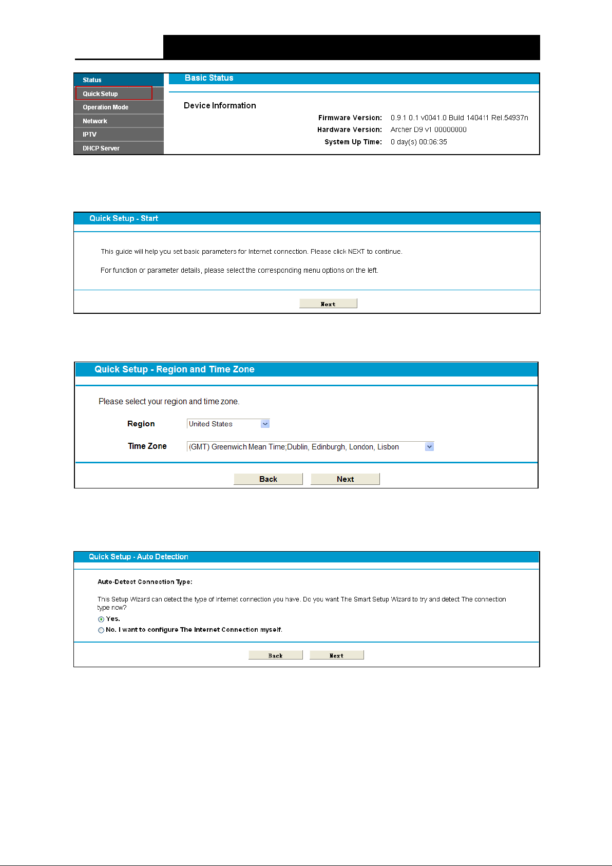
Step 2. After your successful login, you will see the Login screen as shown in Figure 3-3. Click
Quick Setup menu to access Quick Setup Wizard.
11
Page 23
Archer D9
A C1900 Wireless Dual Band Gigabit A DS L 2+ Modem Router User Guide
Figure 3-3
Step 3. The Quick Setup page will appear for you to quickly configure your modem router. Click
Next to continue.
Figure 3-4
Step 4. Select the Region and the Time Zone from the drop-dow n l ist, and then click Next.
Figure 3-5
Step 5. Select Yes to auto detect your connection type and then click Next. It will t ake about two
minutes, please wait.
Figure 3-6
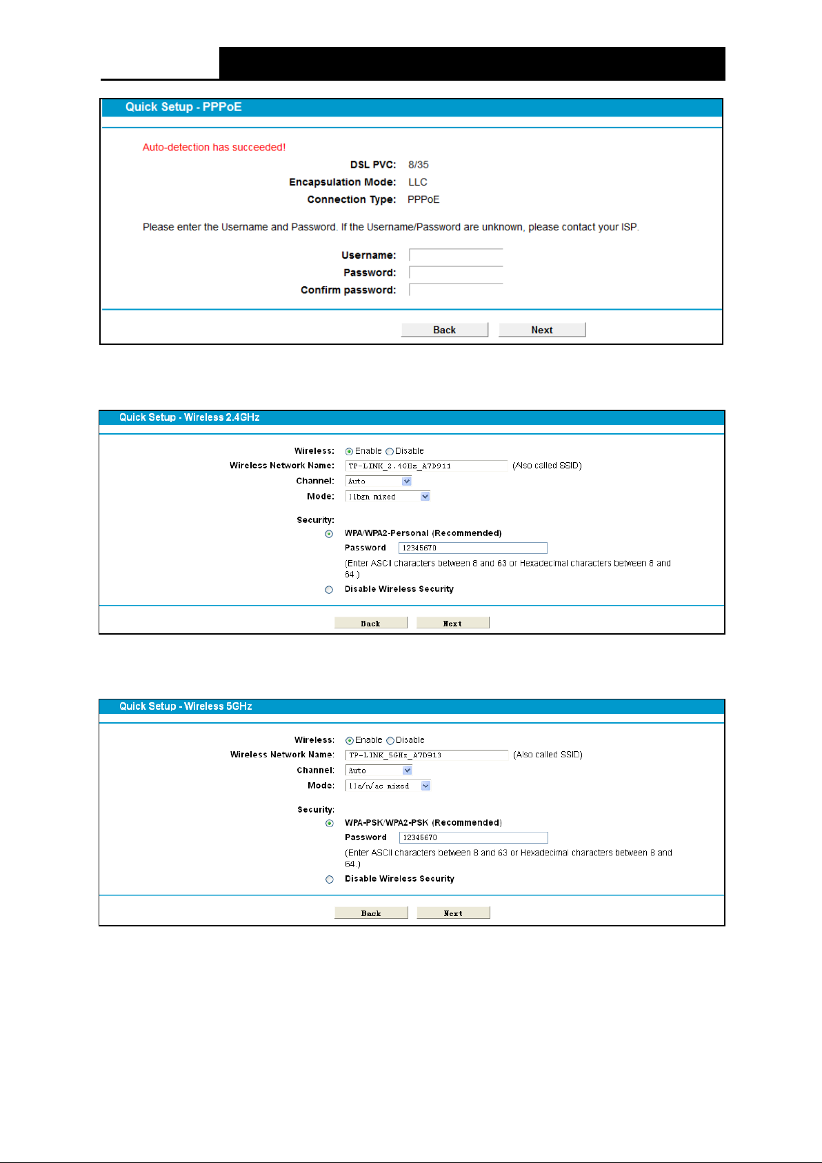
Step 6. Configure parameters for WAN connection. Here we take PPPoE as an example. Enter
usernam e and password provided by your I SP and click Next to c ontinue.
12
Page 24
Archer D9
A C1900 Wireless Dual Band Gigabit A DS L 2+ Modem Router User Guide
Figure 3-7
Step 7. Configure the bas ic parameters for 2.4GHz w ireless network, and then clic k Next.
Figure 3-8
Step 8. Configure the bas ic parameters for 5GHz w ireless network and then cl ick Next.
Figure 3-9
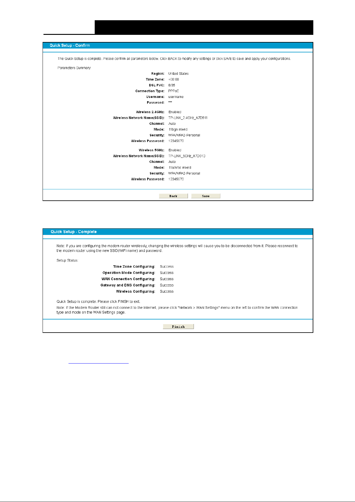
Step 9. On this page, please confirm all parameters. Click Save and wait a moment for your
settings taking effect.
13
Page 25
Archer D9
A C1900 Wireless Dual Band Gigabit A DS L 2+ Modem Router User Guide
Figure 3-10
Step 10. You will see the Complete screen below. Click Finish to complete these setti ngs.
Figure 3-11
The basic settings for your modem router are completed. Please open the web browser and try to
log on to http://www.tp-link.com
to tes t your Internet connect ion.
14
Page 26
Archer D9
A C1900 Wireless Dual Band Gigabit A DS L 2+ Modem Router User Guide
Chapter 4. Configuring the Modem Router
This chapter will show configuration for the key functions on the Web-based m anagem ent page.
4.1 Login
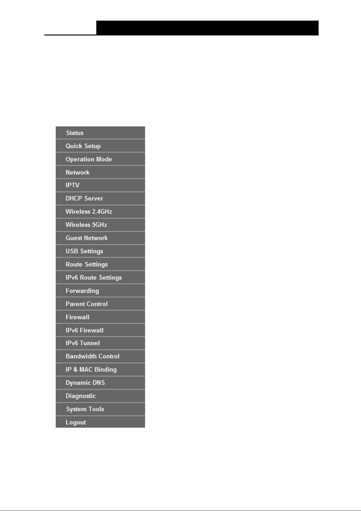
After your successful login, you will see the twenty-three main menus on the left of the Web-based
utili ty. On the right, there are the corresponding explanations and inst ructions.
The detailed ex pl anations for each Web page’s key function are list ed below .
15
Page 27

Archer D9
A C1900 Wireless Dual Band Gigabit A DS L 2+ Modem Router User Guide
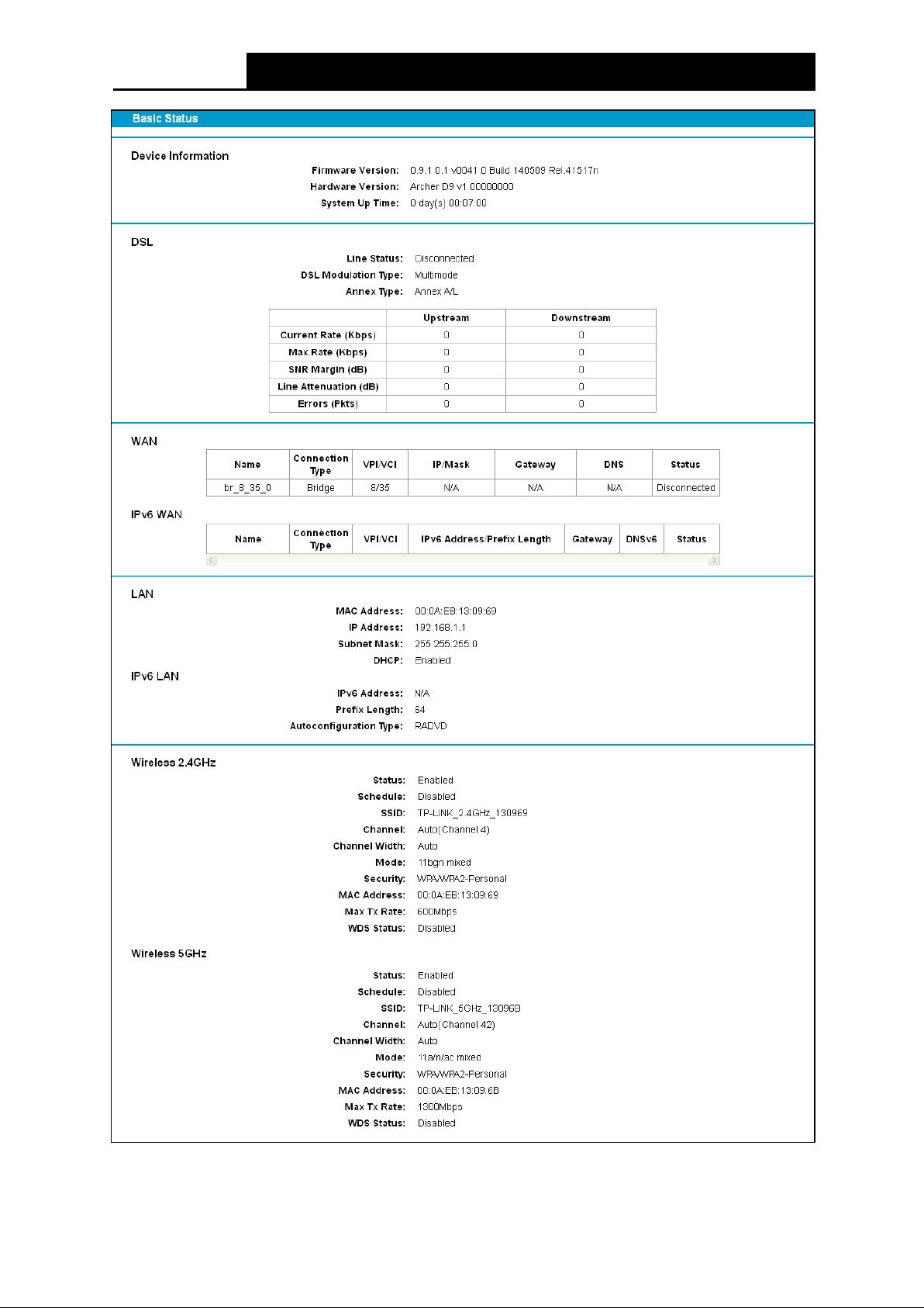
4.2 Status
Choose “Status”, you can see the corresponding information about Device Information, DSL,
WAN, LAN and Wireless.
16
Page 28
Archer D9
A C1900 Wireless Dual Band Gigabit A DS L 2+ Modem Router User Guide
Figure 4-1
17
Page 29
Archer D9
A C1900 Wireless Dual Band Gigabit A DS L 2+ Modem Router User Guide
4.3 Quick Setup
Pleas e refer to 3.2 Quick Installation Guide.
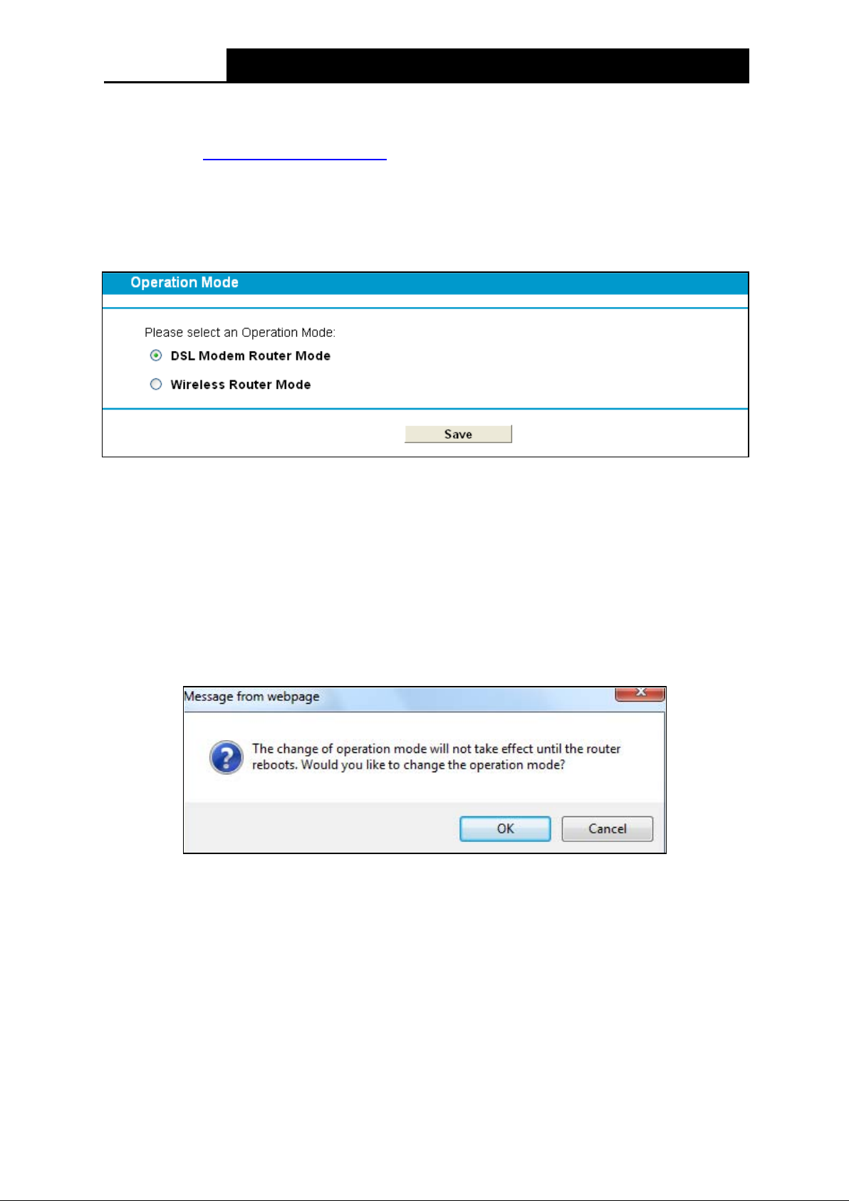
4.4 Operation Mode
Choose “Operation Mode”, and you will see the screen as shown in Figure 4-2. Select your
desired m ode and then click Save.
Figure 4-2
DSL Modem Router Mode: The devi ce enables mul ti-users to s hare I nternet via A DS L using
its ADSL port and share it wirelessly at 1300Mbps wireless speeds over the crystal clear 5GHz
band and 600Mbps over the 2.4GH z band.
Wireless Router Mode: The device enables m ulti-users to s hare I nternet via Ethernet WA N
(EWAN) using its interchangeable LA N 4/WA N port and share it wi relessl y at 1300Mbps
wireless speeds over the crystal clear 5GHz band and 600Mbps ov er the 2.4GH z band.
After you click the Save button, the Note Dialog will appear. Click OK and then the modem router
will re boot. Please wait.
Note Dialog
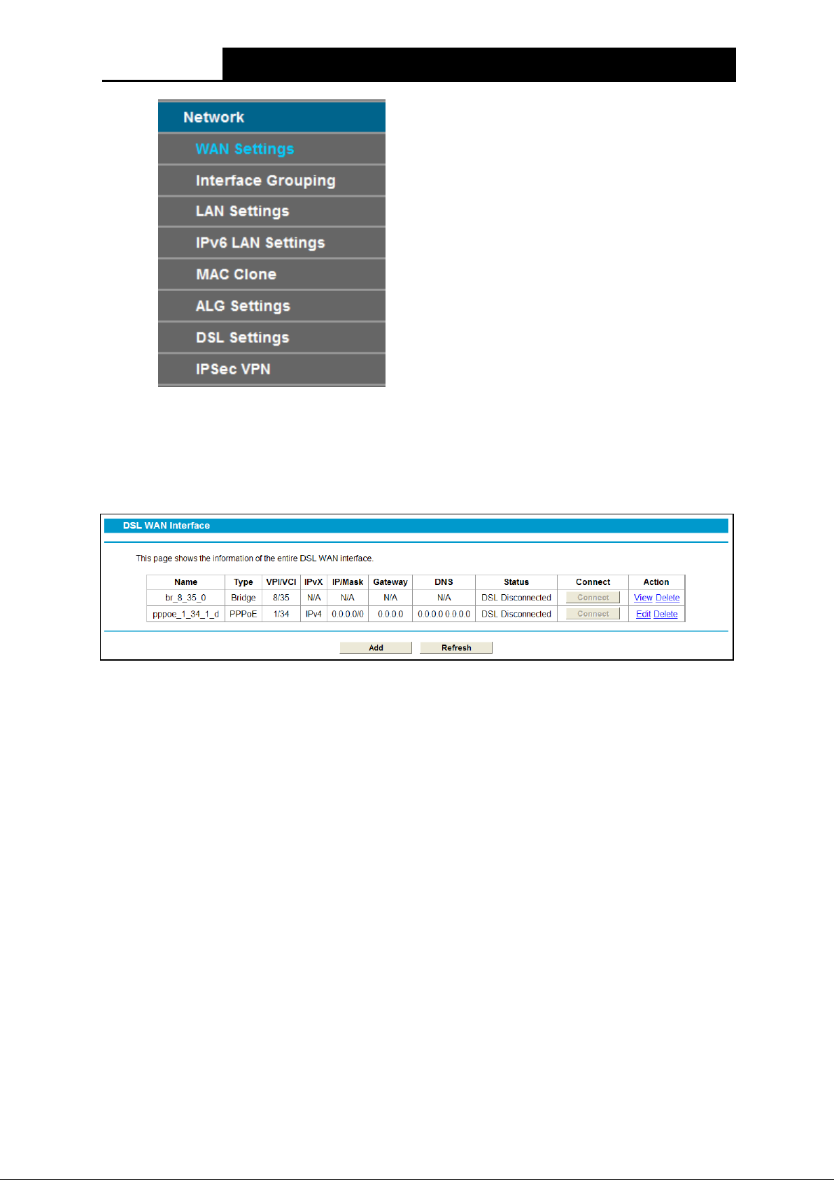
4.5 Network
Choose “Network”, there are many submenus under the main menu. Click any one of them, and
you w i ll be able to configure the corresponding f unction.
18
Page 30
Archer D9
A C1900 Wireless Dual Band Gigabit A DS L 2+ Modem Router User Guide
4.5.1 WAN S e ttin g s
Choose “Network”“WAN Settings”, and you will see the WAN Port Information Table in the
screen similar to Figure 4-3. There are six different configurations for the connection types, which
are Static IP, Dyn amic I P, PPPoE, PPPo A, IPoA and Bridge. You can select the corresponding
types according to your needs.
Figure 4-3
Click Add to add a new entry, you can configure the param eters for ATM and WAN Service in the
next screen (shown in Figure 4-4).
19
Page 31

Archer D9
A C1900 Wireless Dual Band Gigabit A DS L 2+ Modem Router User Guide
Figure 4-4
4.5.1.1 Static IP
Select this option if your ISP provides static IP information to you. You should set static IP address,
I P subnet m ask, and gatew ay address in the screen below .
20
Page 32

Archer D9
A C1900 Wireless Dual Band Gigabit A DS L 2+ Modem Router User Guide
:
Figure 4-5
ATM Configuration:
VPI (0~255): Identifies the virtual path between endpoints in an ATM network. The valid range
is from 0 to 255. Please input the value provided by your I S P.
VCI (1~65535): Identifies the virtual channel endpoints in an ATM networ k. The valid range is
from 1 to 65535 (1 to 31 is reserved for well-known protocols). Please input the value
provided by your ISP.
Click Advance, the advanced selec tions of A TM Configuration can be shown.
Encapsulation Mode: Select the encapsulation mode for the Static IP Address. Her e you
can leave it by default.
ATM Q os Type: Select ATM Qos Type provi ded by your ISP. The default type is UBR.
WA N Servi ce S etup:
Enable IPv4
IP Address: E nter the I P address in dotted-decim al notation provi ded by your I S P .
Subnet Mask: Enter the subnet M ask provided by your I S P , which is usually 255.255.255.0.
Che ck t he box to enable IP v4.
21
Page 33

Archer D9
A C1900 Wireless Dual Band Gigabit A DS L 2+ Modem Router User Guide
Gateway (Optional): Enter the gateway IP address in dotted-decimal notation provided by
your ISP.
DNS Server/ Secondary DNS Server: Here you can set DNS Server (at least one) manually.
The modem router will use the first D NS Serve r for priority.
Default Gateway: Select a WAN Interface from the drop-down list as the IPv4 default
gateway.
Enable IPv6: Check the box to enable IPv6.
IP v6 Address: Enter the IP v6 address provi ded by your I S P.
Prefix Length: Enter the prefix length of the I P v6 address. The default value is 64.
IPv6 Gateway: E nter the gateway IPv6 address provided by your I S P.
IPv6 DNS Server / Se condary IPv6 DNS Server: Here you can set IPv6 DNS Server (at
least one) manually. The Route w ill use this IPv6 DNS Ser ver for priority.
IPv 6 Default Gateway: Select a WAN Interface from the drop-down list as the IPv6 default
gateway.
Click Advance, advanced selecti ons of WAN Service Setup can be shown.
M TU ( b ytes): The default MTU (Maximum Transmission Unit) value is 1500 Bytes. Do not
change the default value unless required by y our I SP .
Enable NAT: This technology translates the IP addresses of a local area network to a
different IP address for the Internet. If this modem router is hosting your network’s connection
to the I nternet, pl ease selec t the check box .
E nabl e Fullcon e N AT: It is a type of N AT, if not enabled, the default N A T wil l act.
Enable SPI Fire wall: The SPI firewall enhances networ k’s security. Select the option to use a
firew al l, or else w ithout a firewal l.
Enable IGMP Proxy: IGMP (Internet Group Management Protocol) is used to manage
multicasting on TCP/IP networks. Some ISPs use IGMP to perform remote configuration for
client devices , such as the modem r outer. It is enabled by defaul t.
Click the Save button to save the s ettings .
4.5.1.2 Dynamic IP
Select Dynamic IP type if your ISP provides the DHCP service, and the modem router will
autom atical ly get IP parameters from your I SP .
22
Page 34

Archer D9
A C1900 Wireless Dual Band Gigabit A DS L 2+ Modem Router User Guide
Figure 4-6
Click Advance, advanced selecti ons for WAN Service Setup can be show n.
MTU (bytes): The default MTU (Maximum Transmission Unit) value is 1500 Bytes. Do not
change the default value unless required by y our I SP .
Enable NAT: This technology transla tes the IP addresses of a local area network to a different
IP address for the Internet. If this modem router is hosting your network’s connection to the
I nternet, pleas e select the check box.
Enable Fullcon e NAT: It is a type of NA T, if not enabled, the defaul t N A T will act.
Enable SPI Firewall: The SPI firewall enhances network’s security. Select the option to use a
firew al l, or else w ithout a firewal l.
Enable IGM P Proxy: IGMP (Internet Group Management Protocol) is used to manage
multicasting on TCP/IP networks. Some ISPs use IGMP to perform remote configuration for
client devices , such as the modem r outer. It is enabled by default.
Get IP with Unicast: It is disabled by default. A fe w IS Ps ’ D HCP Servers do not support the
broadcast applications. When the modem router cannot get the IP address normally, you can
choose this option. (It is rarely required)
Set DNS Server manually: Choose “Set DNS Server manually”, you can set DNS Server
manually here. The modem router will use this DNS Server for priority.
Get IPv6 Add r e ss with Unicast: It is disabled by default. A few IS Ps’ DHCP Server s do not
support the broadcast applications. When the modem router cannot get the IPv6 address
normal ly, you can choose this option. (I t is rarely required.)
23
Page 35

Archer D9
A C1900 Wireless Dual Band Gigabit A DS L 2+ Modem Router User Guide
Se t IPv 6 DNS Se rver manually: Choose “Set IPv6 DNS Server manually”, you can set IPv6
DNS Serv er manually here. The modem router will use this IPv6 D NS Serve r for priority.
Host Nam e: H ere displays m odel number of your modem router.
Click the Save button to save the s ettings .
4.5.1.3 PPPoE
If your ISP provides a PPPoE connection and you need to use an ATM Interface, choose PPPoE
in the drop-down li st, and then the screen w i ll be displayed as below.
Figure 4-7
PPP Username/Password/Confirm Password: Enter the User Name and Password
provided by your ISP. These fields are case-sensitive.
Always on: The connection can be re-established automatically when it is down.
24
Page 36

Archer D9
A C1900 Wireless Dual Band Gigabit A DS L 2+ Modem Router User Guide
Connect on dem and: This mode is dependent on the traffic. If there is no traffic (or Idle ) f or a
pre-specified period of time (MAX Idle Time), the connection will drop down automatically.
And once there is a request for Internet connec tion, i t w i ll be on automatically.
Connect Manually: You can manually control the status of a connection. This mode also
supports the Max Idle Time function as Co nnect on Demand mode. The Internet connection
can be disconnected automatically after a specified inactivity period and re-established when
you attem pt to access the I nt ernet again.
Authentication Type: Select the Authentication Type from the drop-down list, the default
method is AUTO_AUTH, and you can leave it as a default setting.
Enable IPv4: Check thi s box to enable I P v4.
Enable IPv6: Check t his box to enable I P v6.
Default Gateway: Select a WAN connection from the drop-down list as the IPv4 default
gateway.
IPv6 Default Gateway: Select a WAN connection from the drop-down list as the IPv6 default
gateway.
Click Advance, advanced sel ections for WA N Service Setup can be show n.
Service Name/Server Name: Enter the Service Name and Server Name if it was provided by
your ISP. You can leave them blank, if the ISP doesn’t provide them .
M TU ( b ytes): The default MTU (Ma ximu m T ra nsmi ssion Unit) value is 1480 Bytes. Do not
change the default value unless required by y our I SP .
E nabl e Fullcon e N AT: It is a type of N A T, if not enabled, the default NAT will act.
Enable SPI Firewall: The SPI firewall enhances networ k’s security. Select the option to use a
firew al l, or else w ithout a firewal l.
Enable IGMP Proxy: IGMP (Internet Group Management Protocol) is used to manage
multicasting on TCP/IP networks. Some ISPs use IGMP to perform remote configuration for
client devices , such as the modem r outer. It is enabled by default.
Use IP addre ss specified b y I SP: Select this option and enter the IP address provided by
your ISP.
Se t DNS Server manually: Choose “Set DNS Server manually”, you can set DNS Serve r
manually here. The modem router will use this DNS Serve r for priority.
Use IPv6 address spe cifie d by ISP: Choose “Use IPv6 address specified by ISP”, y o u c a n
enter the I Pv 6 address provi ded by your I S P.
Set IPv6 DNS Server manually: Choose “Set IPv6 DNS Server manually”, you can set IPv6
DNS Serv er manually here. The modem router will use this IPv6 D NS Serve r for priority.
Click the Save button to save the s ettings .
4.5.1.4 PPPoA
If your ISP provides a PPPoA connection and you need to use an ATM Interface, choose PPPoA
in the drop-down li st, and then the screen w il l be displayed as below .
The configuration is similar to PPPoE. Please refer to the section 4.5.1.3 PPPoE
part.
25
to configure this
Page 37

Archer D9
A C1900 Wireless Dual Band Gigabit A DS L 2+ Modem Router User Guide
Figure 4-8
4.5.1.5 IPoA
If yo ur ISP provides an IPoA connection, select IPoA option for the Con necti on Type on th e
screen.
26
Page 38

Archer D9
A C1900 Wireless Dual Band Gigabit A DS L 2+ Modem Router User Guide
Figure 4-9
IP Address/Subnet Mask: Enter the IP A ddress and Subnet Mask provided by I S P .
DNS Server/Secondary DNS Server: Type in your preferred DNS server.
Default Gateway: Select a WAN Interface from the drop-down list as the IPv4 default
gateway.
4.5.1.6 Bridge
If you select this type of connection, the modem router can be configured to act as a bridging
device between your LAN and your ISP. Bridges are devices that enable two or more networks to
communicate as if they are two segments of the same physical LAN.
Figure 4-10
27
Page 39

Archer D9
A C1900 Wireless Dual Band Gigabit A DS L 2+ Modem Router User Guide
Note:
After you finish the I nternet configurati on, please c lick Save to m ake the settings take effec t.
4.5.2 Interface Grouping
Choose “Network”“Interface Grouping”, you can view all the current groups on this page
(shown in Figure 4-11).
Figure 4-11
Enable the Virtual LAN Ports feature: Virtual LAN (VLAN) is a group of devices on one or
more LANs that are configured so that they can communicate as if they were attached to the
same LAN. Because VLANs are based on logical instead of physical connections, it is very
flexible for user/host management, bandwidth allocation and resource optimization. If you
want to active the Interface Grouping function, please check the box to enable the Virtual LAN
Ports feature.
Note:
I t is not allowed to disable the VLAN with Ethernet Connection enabl ed.
To support this feature, you must create mapping groups with appropriate LAN and WAN
interfaces us ing the Add button.
Click the Add button. You can add a new interface group in the next screen. For example, if you
want LAN1 and LAN3 to be a group called Group 1 over br _8_35_0 WAN interface, you can refer
to the following figure.
28
Page 40

Archer D9
A C1900 Wireless Dual Band Gigabit A DS L 2+ Modem Router User Guide
Figure 4-12
Click Save to make the entry effective immediately
4.5.3 LAN Settings
Choose “Network”“LAN Settings” menu, and you will see the LAN screen (shown in Figure
4-13). Please confi gure the param eters for LAN ports accordi ng to the descriptions below.
Figure 4-13
IP Address: You can configure the modem router’s IP Address and Subnet Mask for LAN
Interface.
• IP Address: Enter the modem router’s local IP Address, then you can access to the
Web-based U ti lity via the I P Address, the def ault val ue is 192.168.1.1.
• Subnet Mask: Enter the modem router’s Subnet Mask, the default value is 255.255.255.0.
29
Page 41

Archer D9
A C1900 Wireless Dual Band Gigabit A DS L 2+ Modem Router User Guide
Enable IGMP Snooping: IGMP Snooping is the process of listening to IGMP (Internet Group
Management Protocol) network traffic. The feature prevents hosts on a local network from
receivi ng traffic for a mul ticast group they have not expl ici tly joined. I t is enabled by default.
Enable Second IP: You can configure the modem router’s second IP Address and Subnet
Mask for LAN Interface through which you can also access to the Web-based Utility as the
default I P Address and Subnet Mas k.
DHCP Server: The DHCP (Dynamic Host Configuration Protocol) server is enabled by default.
DHCP service will supply IP settings to computers connected to the modem router though the
Ethernet port which are configured to automatically obtain IP settings. When the modem
router is set for DHCP, it becomes the default gateway for DHCP client connected to it. If you
change the IP address of the modem router, you must change the range of IP addresses in
the pool used for DH CP on the LAN.
• Start IP Address: Enter a value for the DHCP server to start with when issuing IP
addresses. The default Start IP Address is 192.168.1.100, and the Start IP Address must
be 192.168.1.100 or greater, but smal ler than 192.168.1.254.
• End IP Address: Enter a value for the DHCP server to end with when issuing IP
addresses. The End IP Address must be smaller than 192.168.1.254. The default End IP
Address is 192.168.1.254.
• Le a sed Ti me: The Leased Time is duration in which a DHCP client can lease its current
dynamic IP address assigned by the modem router. After the dynamic IP address has
expired, the user will be automatically assigned to a new dynamic IP address. The default
is 1440 minutes.
The detailed confi guration about DHCP ser ver , please refer to s ection 4.6 DHCP Server
.
4.5.4 IPv6 LAN Settings
Choose menu “Ne twork”“IPv6 LAN Se t t ing s”, you can configure LAN IPv6 interface for your
modem r outer.
Figure 4-14
Address Auto-configuration Type: Select a type to assign IPv6 addresses to the com puters
in your LAN . RADV D and DH CP v6 S erver are provided.
1) If RADVD is selected, it doesn’t need to be configured.
30
Page 42

Archer D9
A C1900 Wireless Dual Band Gigabit A DS L 2+ Modem Router User Guide
2) If DHCPv6 Server is selected, pl ease com plet e the foll ow ing parameters.
Figure 4-15
• Start IPv6 A ddress: Enter a value for the DHCPv6 server to start with when issuing IPv6
addresses.
• End IPv6 Address: Enter a value for the DHCPv6 server to end with when issuing IPv6
addresses.
• Le ased Ti me: The Leased Time is the duration in which a DHCP client can lease its
current dynamic IPv6 address assigned by the modem router. After the dynamic IPv6
address has expired, the user will be automatically assigned a new dynamic IPv6
address. The default i s 86400 seconds.
Site Prefix Configuration Type: Select a type to assign prefix to IPv6 addresses. Delegated
and Stati c are provided.
1) If Delegated is selec ted, please complete the following parameters.
Figure 4-16
• Prefix De le gated WAN Connection: Select a WAN connection form the drop-down list
to assi gn prefix .
2) If Static is selected, please c om plete the follow i ng param eters.
Figure 4-17
• Site Prefix: Enter a value for the site prefix.
• Si te Prefix L ength : Enter a value f or the site prefi x length.
Click the Save button to save the settings.
31
Page 43

Archer D9
A C1900 Wireless Dual Band Gigabit A DS L 2+ Modem Router User Guide
4.5.5 MAC Clone
Choose menu “Ne twork”“MAC Clone”, you can configure the MAC address of the WAN
I nterface as show n below.
The WAN Interface List displays the WAN Interfaces you have configured on the section
WAN Settings and its default MAC Address. You can select the corresponding WAN Interface from
the drop-down list and click Clone MAC To button to clone your current PC MAC, and then click
Save.
Figure 4-18
Note:
Only the WAN Ports can use MAC Address Clone function. All the clone MAC addresses must not
be the sam e wi th each other.
4.5.1
4.5.6 ALG Settings
Choose menu “Ne twork”“ALG Setting s ”, and then you can configure the basic security in the
screen as shown in Figure 4-19.
Figure 4-19
Virtual Private Networ k (VPN): VPN Pass-through must be enabled if you want to allow VPN
tunnels usi ng VP N protocol s to pass through the modem router.
• PPTP Pass-through: PPTP (Point-to-Point Tunneling Protocol) allows the
Point-to-Point Protocol (PPP) to be tunneled through an IP network. To allow PPTP
tunnels to pass through the modem r outer , click Enable.
32
Page 44

Archer D9
A C1900 Wireless Dual Band Gigabit A DS L 2+ Modem Router User Guide
• L2TP Pass-through: L2TP (Layer Two Tunneling Protocol) is the method used to
enable Point-to-Point sessions via the Internet on the Layer Two level. To allow L2T P
tunnels to pass through the modem r outer , click Enable.
• IPSec Pass-through: IPSec (Internet Protocol security) is a suite of protocols for
ensuring private, secure communications over Internet Protocol (IP) networks, through
the use of cryptographic security services. To allow IPSec tunnels to pass through the
modem router, click Enable.
Application Laye r Gateway (ALG): It is recommended to enable ALG (Application Layer
Gateway) because ALG allows customized Network Address Translation (NAT) traversal
filters to be plugged into the gateway to support address and port translation for certain
applicat ion lay er "control/data" protocols suc h a s FTP , TFTP etc.
• FTP ALG: To allow FTP cl ients and servers to transfer data ac ross N A T, click Enable.
• TFTP ALG: To allow TFTP clients and servers to transfer data across NAT, click
Enable.
• H323 ALG: To allow H323 clients and servers to transfer data across NAT, click
Enable.
• SIP ALG: To allow SIP clients and servers to transfer data acros s N A T, click Enable.
Click the Save button to save your settings.
4.5.7 DSL Setti ngs
Choose “Advanced Setup”“DSL Settings”, you can select the DSL Modulation Type and the
Annex T ype in the next screen. The DSL settings can be changed when you meet the physical
connection probl em . Pl ease check the proper settings with your I nternet servi ce provider.
Figure 4-20
DSL Modulation Type: Select the DSL operation Modulation Type which your DSL
connection us es.
Annex Type : Select the DSL operation Annex Type which your DS L connecti on uses.
Click the Save button to save y our settings .
4.5.8 IPSec VPN
Choose “Network”“IPSec VPN”, you can Add/Remove or Enable/Disable the IPSec tunnel
connections on the screen as shown in Figure 4-21.
33
Page 45

Archer D9
A C1900 Wireless Dual Band Gigabit A DS L 2+ Modem Router User Guide
Figure 4-21
This section will guide you to configure a VPN tunnel between two Archer D9s. The topology is as
follows.
Note:
You could also use other VPN Routers to set VPN tunnels with Archer D9. Archer D9 supports up
to 10 VP N tunnels sim ul taneously .
Click Add New Connection in Figure 4-21 and then you will enter the screen shown in Figure
4-22.
34
Page 46

Archer D9
A C1900 Wireless Dual Band Gigabit A DS L 2+ Modem Router User Guide
Figure 4-22
IPS ec Connection Na m e: Enter a nam e for your VPN.
Re mote IPSe c Gate way Address (URL): Enter the destination gateway IP address which is
the public WAN IP or Domain Name of the remote VPN server endpoint. (For example: Input
219.134.112.247 in Device1, I nput 219.134.112.246 in Device 2)
Tunnel access from local IP ad dresses: Choose Subnet if you want the Whole LAN to join
the VPN network, or else choose Single Address if you want single IP to join the VPN network.
I P Add re ss f or VPN: Enter the IP address of your LAN. (F or example: Input 192.168.1.1 in
Device1, Input 192.168.2.1 in Device2)
IP Subnetmask: Enter the Subnet mask of your LAN. ( For example: Input 255.255.255.0 in
both Device1 and Device2)
Tunnel acce ss f rom remote IP addresses: Choose Subnet if you want the Remote Whole
LAN to join the VPN net work, or else choose Single Address if you want single IP to join the
VPN network.
IP Address for VPN: Enter the IP address of the Remote LAN. ( For example: Input
192.168.2.1 in Device1,Input 192.168.1.1 in Device2)
IP Subnetmask: Enter the subnetmask of the remote LAN. ( For example: Input
255.255.255.0 in both Device1 and Device2)
Key Exchange Method: Select Auto (IKE) or Manual.
Authentica tio n Me tho d: Select Pre-Shar ed Key (recommended).
Pre-Shared Key: Input t he Pre-Shared key for Authenti cati on. (For example: Input 12345678)
Perfect Forward Secrecy: P FS is an additional securi ty protocol .
After complete the basic settings and click Save/Apply in both Device1 and Device2, PCs in LAN1
could communicate with PCs in remote LAN2. (For example: You can ping the IP address of PC2
which is 192.168.2.100 in PC1)
Note:
The VPN Servers Endpoint from both ends must use the same pre-shared keys and Perfect
Forw ard Secrecy setti ngs.
35
Page 47

Archer D9
A C1900 Wireless Dual Band Gigabit A DS L 2+ Modem Router User Guide
Click Show Advanced Settings and then you can configure the Advanced Settings. We
recommend y ou leave the A dvanced S ett ings as default value.
Figure 4-23
Mode: Select Main Mode to configure the standard negotiation parameters for IKE phase1.
Select Aggressive Mode to configure IKE phase1 of the VPN Tunnel to carry out negotiation
in a shorter amount of time. (N ot Recomm ended-Less Secure)
Note:
The difference between the two modes is that aggressive mode will pass more information in
fewer packets, with the benefit of slightly faster connection establishment, at the cost of
transmitting the identities of the security firewall in the clear. When using aggressive mode, some
configuration parameters such as Diffie-Hellman groups and PFS can not be negotiated, resulting
in a greater importance of havi ng "compati ble" confi guration on both ends.
Key Life Time: Enter the number of seconds for the IPSec lifetime. It is t he period of time to
pass before establishing a new IPSec security association (SA) with the remote endpoint. The
default val ue is 3600.
If you want to change the default settings of Advanced Settings, please make sure that both VPN
server endpoints use the same Encryption Algorithm, Integrity Algorithm, Diffie-Hellman Group
and Key Life time in both phase1 and phase2.
Note:
4.6 IPTV
Choose “IPTV”, and you will see the screen as shown in Figure 4-24.
36
Page 48

Archer D9
A C1900 Wireless Dual Band Gigabit A DS L 2+ Modem Router User Guide
Figure 4-24
Enable IPTV: Check t he box to enable I PTV function.
VPI (0~255): Identifies the virtual path between endpoints in an ATM network. The valid range
is from 0 to 255. Please input the value provided by your I S P.
VCI (1~65535): Identifies the virtual channel endpoints in an ATM network. The valid range is
from 1 to 65535 (1 to 31 is reserved for well-known protocols). Please input the value
provided by your ISP.
Click the Save button to save y our settings.
4.7 DHC P Server
Choose “DHCP Server”, you can see the nex t subm enus:
Cli ck any of them, and you wi ll be able to configure the corresponding functi on.
4.7.1 DHCP Set ti ngs
Choose menu “DHCP Serve r”“DHCP Settings”, you can configure the DHCP Server o n the
page as shown in Figure 4-25.The modem router is set up by default as a DHCP (Dynamic Host
Configuration Protocol) server, which provides the TCP/IP configuration for all the PC(s) that are
connected to the modem r outer on the LAN .
37
Page 49

Archer D9
A C1900 Wireless Dual Band Gigabit A DS L 2+ Modem Router User Guide
Figure 4-25
Group/ IP Address/ Subnet Mask: Displays group name, IP address and subnet mask.
The parameters c an be configured on the Interface Grouping page and LAN Settings
page.
DHCP Server: If enabled, the modem router will work as a DHCP server, which provides the
TCP/IP confi guration for all the PC(s) that are connected to it on the LAN .
Start IP Ad dress: Enter a value for the DHCP server to start with when issuing IP addresses.
Because the default IP address for the modem router is 192.168.1.1, the default Start IP
Address is 192.168.1.100, and the Start IP Address must be 192.168.1.100 or greater , but
sm aller than 192.168.1.254.
End IP Addre ss: Enter a value for the DHCP server to end with when issuing IP addresses.
The End IP Address must be smaller than 192.168.1.254. The default End IP Address is
192.168.1.254.
Lease Time: The Leased Time is the amount of time in which a DHCP client can lease its
current dynamic IP address assigned by the modem router. After the dynamic IP address has
expired, the user will be automatically assigned a new dynamic IP address. The default is
1440 minutes.
Default Gate way (Optional.): It i s suggested to input the IP address of the LAN port of the
modem router. The default v alue is 192.168.1.1.
D efault Dom a in (Optional.): I nput the dom ain name of your netw ork.
Primary DNS (Optional.): I nput the DNS I P address provided by your IS P.
Secondary DNS (Optional.): Input the IP address of another DNS server if your ISP provides
two DNS ser vers.
DHCP Relay: Select Re lay, then you will see the next screen, and the modem r outer will work
as a DHCP Relay. A DHCP relay is a computer that forwards DHCP data between computers
that request IP addresses and the DHCP server that assigns the addresses. Each of the
device's interfaces can be configured as a DHCP relay. If it is enabled, the DHCP requests
from local PCs will forward to the DHCP server runs on WAN side. To have this function
working properly, please run on router mode only, disable the DHCP server on the LAN por t,
and mak e sure the routing table has the correct routing entry.
38
Page 50

Archer D9
A C1900 Wireless Dual Band Gigabit A DS L 2+ Modem Router User Guide
Note:
1) To use the DHCP server function of the modem router, you must configure all computers on
the LAN as "Obtai n an I P A ddress autom ati call y".
2) You have to dis able NAT of the W A N connecti ons, or the DHCP Relay may not take effect.
3) I f you select Disabled, the DH C P func tion will not take effect .
Click the Save button to save y our settings.
4.7.2 C lients L is t
Choose menu “DHCP Server ”“Clients List”, you can view the information about the clients
attached to the modem router in the screen as shown in Figure 4-26.
Figure 4-26
Client Name: The name of the DH CP cli ent.
MAC Addre ss: The M AC address of the DH CP client.
IP Address: The I P address that the modem router has alloc ated to the DH CP client.
Valid Time: The time of the DHCP client leased. After the dynamic IP address has expired,
a new dynamic IP address will be automatically assigned to the user.
Click the Refresh button to update thi s page.
4.7.3 Address Reservation
Choose menu “DHCP Server”“Address Reservation”, you can view and add a reserved
address for clients via the next screen (shown in Figure 4-27).When you specify a reserved IP
address for a PC on the LAN, that PC will always receive the same IP address each time when it
accesses the DHCP server. Reserved IP addresses should be assigned to the servers that require
permanent IP set tings.
39
Page 51

Archer D9
A C1900 Wireless Dual Band Gigabit A DS L 2+ Modem Router User Guide
Figure 4-27
MAC Addre ss: The MAC address of the PC for which you want to reserve an IP address.
IP Address: The I P address reserved for the PC by the modem router.
Status: The st atus of this entry, either Enabled or Disabled.
To Reserve an IP address:
1. Click the Add New button. Then Figure 4-28 will pop up.
2. Enter the MAC address (in XX:XX:XX:XX:XX:XX format.) and IP address (in dotted-decimal
notation) of the com puter for w hic h you w ant to reserve an I P address.
3. Click the Save button.
Figure 4-28
T o m odify or delete an existing en try :
1. Click Edit in the entry you w ant to modify the entry.
2. Modify the information.
3. Click the Save button.
Click the Enable/Disable Selected button to m ake selected entries enabled/disabled.
Click the Delete Selected button to delete the selected ent ries.
4.7.4 Condit i ona l Pool
Choose m enu “DHCP Server”“Con ditiona l P ool”, you can s ee the nex t screen (show n in
Figure 4-29). This page displ ays v endor class s ettings and allows you to set parameters for
vendor class by clicki ng corresponding buttons .
40
Page 52

Archer D9
A C1900 Wireless Dual Band Gigabit A DS L 2+ Modem Router User Guide
Figure 4-29
To add a vendor class:
1. Click the Add New button. Then Figure 4-30 will pop up.
2. Enter param eters for the vendor cl ass.
Click the Save button.
Figure 4-30
T o m odify or delete an existing en try :
1. Click Edit in the entry you w ant to modif y the entry.
2. Modify the information.
3. Click the Save button.
Click the Enable/Disable Selected button to m ake selected entries enabled/disabled.
Click the Delete Selected button to delete the s elected entri es.
41
Page 53

Archer D9
A C1900 Wireless Dual Band Gigabit A DS L 2+ Modem Router User Guide
4.8 Wireless 2.4GHz
There are seven submenus under the Wireless 2.4 GHz menu: Basic Se ttings, WPS Se tt ing s,
Wireless Security, Wireless Schedule, Wirele ss MAC Filtering, Wireless Advanced and
Wireless Status. Cli ck any of them , and you wi ll be able to configure the corresponding functi on.
4.8.1 Basic Settings
Choose menu “Wireless 2.4GHz” → “Basic Settings”, you can configure the basic settings for
the w irel ess netw ork of 2.4GH z on this page.
Figure 4-31
SSID: Wireless network name. Enter a desired SSID which is case-sensitive and must not
exceed 32 characters. The default SSID is TP-LINK_2.4GHz_XXXXXX (xx is the last six
numbers of MAC address).
Region: Select your region from the dr op-down list. This field specifies the region where the
wireless function of the modem router can be used. It may be illegal to use the wireless
function of the modem router in a region other than one of those specified in this field. If your
country or region is not li sted, please contact your l ocal government agency for assi stance.
Note:
Lim ited by local l aw regul a tio ns, versi o n for N orth A m eri ca does not have regio n sel e ct i on option.
Mode
11b only: Select if all of your wireless clients are 802.11b.
: Select the desi red m ode.
42
Page 54

Archer D9
A C1900 Wireless Dual Band Gigabit A DS L 2+ Modem Router User Guide
11g only: Select if all of your wireless clients are 802.11g.
11n only: Select only if all of your wireless clients are 802.11n.
11bg mixed: Select if you are using both 802.11b and 802.11g wireless clients.
11bgn mixed: Sel ect if you are using a mix of 802.11b, 11g, and 11n wireless clients.
When 802.11g mode is selected, only 802.11g wireless stations can be connected to the
modem r outer. When 802.11n mode is selected, only 802.11n wireless stations can connect
to the modem router. It is strongly recommended that you set the Mode to 802.11bgn mixed,
and all of 802.11b, 802.11g, and 802.11n wireless stations can connect to the modem router.
Channel: Select the channel you want to use from the drop-down list. This field determines
which operating frequency will be used. It is not necessary to change the wireless channel
unless y ou notice i nterference problem s with another nearby access point.
Channel Width: Select the channel width from the drop-down list
autom atic, w hich can adjust the c hannel w i dth for your clients automatically.
Note:
If 11b only, 11g only, or 11bg mixe d is selected in the Mode field, the Channel Width selecting
field w ill turn grey and the value w il l become 20M, w hich is unable to be changed.
Enable SSID Broadcast: When wireless clients survey the local area for wireless networks to
associate with, they will detect the SSID broadcast by the modem router. If this checkbox is
selected, the wireless router w ill broadcast its nam e (SS I D ) on the air.
En able WDS: With this function, the modem router can bridge two or more Wlans. If this
checkbox is selected, you will need to set the following parameters as shown in the figure
below. Make sure the follow i ng settings are correct.
. The default setting is
SSID (t o be br idged): The SSID of the AP your modem router is going to connect to as a
client. Y ou can also use the search function to select the S SI D to join.
BSSI D (to be bridged): The BSSID of the AP your modem r outer is going to connect to as a
client . You can also use the search function t o select the BS S I D to join.
Scan: Click th is button, you can search the A P w hich runs in the current channel.
Ke y type : This option should be chosen according to the AP's security configuration. It is
recom m ended that the security type is the sam e as your AP's security type
WEP Ind ex: This option should be chosen if the key type is WEP(ASCII) or WEP(HEX). It
indicates the index of the WEP key.
43
Page 55

Archer D9
A C1900 Wireless Dual Band Gigabit A DS L 2+ Modem Router User Guide
Authentication Type: This option should be chosen if the key type is WEP(ASCII) or
WE P(HEX ). It indicates the authoriz ation ty pe of the Root AP.
Password
the password in this blank.
Click Save to save your settings .
: If t he AP your modem router is going to connect needs passwor d, you need to fill
4.8.2 WPS Settings
This section will guide you to add a new wireless device to an existing network quickly by WPS
(also cal led QSS) function.
a). Choose m enu “WPS Sett in gs ”, and you will see the nex t screen (shown in Figure 4-32).
Figure 4-32
WPS: Enable or disable the WPS function here.
Current PIN : The current value of the modem router's PIN is displayed here.
Restore PIN: R estore the P I N of the modem router to its default.
Generate New PIN: Click th is but ton to get a new random PIN code. You can ensure the
netw ork security by generating a new PI N .
Add device: You can add a new device to the existing network manually by clicking this
button.
b). To add a new device:
If the wireless adapter supports Wi-Fi Protected Setup (WPS), you can establish a wireless
connection between wireless adapter and modem router using either Push Button Configuration
(PBC) method or PIN method.
Note:
To build a successful connection by WPS, you should also do the corresponding configuration of
the new device for WPS function m eanwhile.
I. Us e t h e Wi-Fi P rotected Setup B utto n
U se this m ethod if your client device has a Wi-Fi Protected Setup button.
Step 1: Press the WPS button on the side of the modem router, as show n in the following fi gure.
44
Page 56

Archer D9
A C1900 Wireless Dual Band Gigabit A DS L 2+ Modem Router User Guide
You can also keep the default WPS Status as Enabled and click the Add device button in Figure
4-32, then Choose “Pr ess th e WPS button of the new device within the next two minutes” and
click Connect. (Shown i n the foll ow ing figure)
Figure 4-33
Step 2: Press and hold the WPS button of the client device directly.
Step 3: The Wi-Fi Protected Setup LED flashes for two minutes during the Wi-Fi Protected Setup
process.
Step 4: When the WPS LED is on, the client device has successfully connected to the modem
router.
Refer back to your client device or its docum entation f or further instructions.
II. E nter the client device’s P IN on the modem rout er
U se this m ethod if your client device has a Wi-Fi Protected S etup PIN number.
Step 1: Keep the default WPS Status as Enabled and click the Add device button in Figure
4-32, then the following screen will appear.
Figure 4-34
Step 2: Enter the PIN number from the client device in the field on the above WPS screen. Then
click Connect button.
Step 3: “Connect successfully” will appear on the screen of Figure 4-34, which means the
client device has succes sfull y connected to the modem router.
III. Enter the mode m rout er’s P IN on y our c lient devi ce
U se this m ethod if your client device as ks for the modem router’s PI N number.
Step 1: On the client device, enter the PIN number listed on the modem router’s Wi-Fi Protected
Setup sc reen. (I t is also label ed on the back of the modem router.)
45
Page 57

Archer D9
A C1900 Wireless Dual Band Gigabit A DS L 2+ Modem Router User Guide
Step 2: The Wi-Fi Protected Setup LED flashes for two minutes during the Wi-Fi Protected
Setup proces s.
Step 3: When the WPS LED is on, the client device has successfully connected to the modem
router.
Step 4: Refer back to your cli ent device or its documentati on for further instructions.
Note:
1 The WPS LED on the modem router will light green for five minutes if the device has been
2 The WPS function cannot be configured if the Wireless Function of the modem router is
success full y added to the network .
disabled. Pl ease make sure the Wireless Function is enabled before configuring t he WPS.
4.8.3 Wireless Security
Choose menu “Wire less 2.4GHz”” Wireless Se curity”, you can configure the security settings
of your wireless network.
There are three wireless security modes supported by the modem router: WPA/WPA2 – Personal,
WPA/WPA2 – Enterprise, WEP (Wired Equi valent P rivac y).
Figure 4-35
Disable Wireless Security: If you do not want to use wireless security, check this radio
button. But it’s strongly recom m ended to choose one of the below modes to ensure security.
WPA/WPA2-Personal: It’s the WPA/WPA2 authentication type based on pre-shared
passphrase. It is chose n by default.
• Authentication Type: You can choose the type for the WPA/WPA2-Personal security on
the drop-down list. The default setting is Auto, which can select WPA-PSK
as authenticat ion type autom ati call y based on the w ireless station's capabili ty and request.
46
or WPA2-PSK
Page 58

Archer D9
A C1900 Wireless Dual Band Gigabit A DS L 2+ Modem Router User Guide
• Encryption: You can select Auto, TKIP or AES as Encryption.
• Wireless Password: You can enter ASCII characters between 8 and 63 characters or 8 to
64 Hexadecimal characters. The default password is the same with the default PIN code,
w hic h is labeled on the back of the modem router or can be found in Figure 4-32.
• Group Ke y Update Pe riod: Specify the group key update interval in seconds. The value
should be 30 or above. Enter 0 to disable the update.
WPA/WPA2 – Enterprise: It’s based on Radius Server.
• Authentication Type: Authentication Type: You can choose the type for the
WPA/WPA2-Personal security on the drop-down list. The default setting is Auto, which can
select WPA-PSK
or WPA2-PSK as authentication type automatically based on the wireless
station's c apabili ty and request.
• Encryption: You can select Auto, TKIP or AES as Encryption.
• RADIUS Server IP: Enter the IP address of the Radius Server.
• RADIUS Server Port: Enter the port that radi us servi ce used.
• RAD IUS Server Password: Enter the password for the Radius Serv er.
• Group Ke y Update Pe riod: Specify the group key update interval in seconds. The value
should be 30 or above. Enter 0 to disable the update.
WEP: It is based on the I EE E 802.11 standard.
• Authentication Type: You can choose the type for the WPA/WPA2-Personal security on
the drop-down list. The default setting is Auto, which can select WPA-PSK
or WPA2-PSK
as authenticat ion type autom ati call y based on the w ireless station's capabili ty and request.
• WEP Ke y For mat: Hexadecimal and ASCII formats are provided here. Hexadecimal
format stands for any combination of hexadecimal digits (0-9, a-f, A-F) in the specified
length. ASCII format stands for any combination of keyboard characters in the specified
length.
• W EP Ke y: Select whi ch of the four keys w i ll be used and enter the matc hing WE P key that
you create. Mak e sure these values are identical on all wireless stations in your network.
47
Page 59

Archer D9
A C1900 Wireless Dual Band Gigabit A DS L 2+ Modem Router User Guide
• Key Type: You can select the WEP key length (64-bit, or 128-bit.) for encryption.
"Dis abled" m eans this WEP key entry is invalid.
64-bit:
not promoted) or 5 AS CI I characters.
128-bit: You can enter 26 hex adecim al digits (any combinati on of 0-9, a-f, A-F , zero key is
not promoted) or 13 ASCII characters.
Be sure to click the Save button to save your set tings on thi s page.
You can enter 10 hexadecimal digits (any combination of 0-9, a-f, A-F, zero key is
4.8.4 Wireless Schedule
Choose menu “Wireless 2.4GHz”“Wire less Schedu le”, you can configure the Task Schedule
as shown below.
Figure 4-36
Note:
The time you set is the period you need the wireless off.
Before configure the wireless schedule, please set system time first which refer to
Settings, then you can enabl e or disable Wireless Schedule.
Apply To: Select the day or days you w ant to sw itch the wireless off.
Start Time, End Time: You can select all day-24 hours or you may enter the Start Time and
End Time in the corresponding field.
Add: Click this button to add your selected tim e to the below table.
Click the Clear Schedule butt on to clear your setti ngs in the table.
Click Save to com plete t he settings .
48
4.23.2 Time
Page 60

Archer D9
A C1900 Wireless Dual Band Gigabit A DS L 2+ Modem Router User Guide
4.8.5 Wire le s s MAC Filte rin g
Choose menu “Wireless 2.4GHz” ”W ire le ss M AC Filtering”, you can control the wireless
access by configuring the Wireless MA C Filtering function, show n i n Figure 4-37.
Figure 4-37
To filter w ireless users by MAC Address, click Enable. The default setti ng is Disabled.
M AC Address: The w ireless station's MA C address that you want to filter.
Status: The status of this entry, either Enabled or Disabled.
Host: The wi reless network name (SSID).
Description: A si m ple description of the w ireles s station.
To Add a Wireless MAC Address filtering entry, click the Add New button. The following page will
appear, show n in Figure 4-38:
Figure 4-38
T o add or m odify a MA C Address Fil tering entry, follow t h ese i nstr uctions :
1. Enter the appropriate MAC Address into the M AC Ad d re s s field. The format of the MAC
Address is XX:XX:XX:XX:XX:XX (X is any hexadecimal digit). For example:
00:1D:0F:11:22:33.
2. Give a simple description for the wireless station in the Description field. For example:
Wirel ess station A.
3. Select Enabled or Disabled for thi s entry from the Status drop-dow n li st.
4. Select Host from the drop-dow n li st.
5. Click the Save button to save thi s entry.
49
Page 61

Archer D9
A C1900 Wireless Dual Band Gigabit A DS L 2+ Modem Router User Guide
To edit or delet e an exist ing entry :
1. Click the Edit in the entry you want to modify.
2. Modify the information.
3. Click the Save button.
Click the Enable/ Disabled Selected button to mak e selected entries enabled or disabled.
Click the Delete Selected button to delete t he select ed entries.
For exampl e: If you desir e that the wireless station A with MAC address 00:1D:0F:11:22:33 and the
wireless station B with MAC address 00:0A:EB:00:07:5F are able to access the modem router, bu t
all the other wireless stations cannot access the Modem router, you can configure the Wireless
MA C Address Fil t eri ng lis t by foll ow i ng these steps :
1. Click the Enable but ton to enable thi s functi on.
2. Select the radio button “Allow the stations specified by any e nabled entries in the list to
access” for Filtering Rules.
3. Delete all or disable all entries if there are any entries al ready.
4. Click the
Add New button.
1) Enter the MAC address
2) Enter w irel ess station A/B in the Description field.
3) Select Enabled i n the Status drop-down list.
4) Select TP-LINK_2.4GHz for the Host.
5) Click th e Save button.
00:1D:0F:11:22:33/00:0A:EB:00:07:5F in the MAC Address field.
The filtering rul es that configured should be si m ilar to the following list:
4.8.6 Wireless Advanced
Choose menu “Wireless 2.4GHz””Wireless Advanced”, you can configure the advanced
settings of your wireless network.
50
Page 62

Archer D9
A C1900 Wireless Dual Band Gigabit A DS L 2+ Modem Router User Guide
Figure 4-39
Transmit Power : Here you can specify the transmit power of the modem router. You can
select 100%, 50% or 25%. 100% is the default s etting and is recom m ended.
Beacon Interval: Enter a value between 25-1000 milliseconds for Beacon Interval here. The
beacons are the packets sent by the modem router to synchronize a wireless network.
Beacon Interval value determines t he tim e interval of the beacons. The default value is 100.
RTS Threshold: Here you can specify the RTS (Request to Send) Threshold. If the packet is
larger than the specified RT S Threshold size, the modem router will send RTS frames to a
particular receiving station and negotiate the sending of a data frame. The default value is
2346.
Fragmentation Threshold: This value is the maximum size determining whether packets
will be fragmented. Setting the Fragmentation Threshold too low may result in poor network
performance because of excessive packets. 2346 is the default setting and is recommended.
DTIM Interval: This value determines the interval of the Delivery Traffic Indication Message
(DTIM). A DTIM field is a countdown field informing clients of the next window for listening to
broadcast and multicast messages. When the modem router has buffered broadcast or
multicast messages for associated clients, it sends the next DTIM with a DTIM Interval value.
You can specify the value between 1-255 Beacon Intervals. The default value is 1, which
indicates the DTIM Interval is the same as Beacon Interval.
Enable Short GI: It is recommended to Enable Short GI, which will increase the data
capacity by reducing the guard interval ti m e.
Enabled Client Isolation: This function can isolate wireless stations on your network from
each other. Wireless devices will be able to communicate with the modem router but not with
each other. Client isolation is disabled by default.
Enable WMM: This function guarantee the packets with high-priority messages being
transm itted preferenti ally . It is strongly recom m ended to enable WM M .
Note:
If you are not familiar with the setting items in this page, it's strongly recommended to keep the
provided default values; ot herw is e it may result in lower wireless network performance.
51
Page 63

Archer D9
A C1900 Wireless Dual Band Gigabit A DS L 2+ Modem Router User Guide
4.8.7 Wireless Status
Choose menu “Wire less 2.4GHz””Wireless Status”, you can see the MAC Address, Current
Status , Recei ved Packets and Sent Pac kets for each connected w i reless station.
Figure 4-40
M AC Address: The connected w i reless st ation's M A C address.
Current Statu s: The connected wireless stati on's running stat us.
Received Packets : P ackets received by t he station.
Sent Packets: P ackets sent by the station.
SSID: The w ireless network name.
Click on the Refresh button to update thi s page.
4.9 Wireless 5GHz
There are seven submenus under the Wireless 5 GHz menu: Basic Settings, WPS Se tting s,
Wireless Security, Wireless Schedule, Wirele ss MAC Filtering, Wireless Advanced and
Wireless Status. C lic k any of them , and you w il l be able to configure the c orresponding functi on.
4.9.1 Basic Settings
Choose menu “Wireless 5GHz” → “Basic Settings”, you can configure the basic settings for the
wireless network of 5GHz on thi s page.
52
Page 64

Archer D9
A C1900 Wireless Dual Band Gigabit A DS L 2+ Modem Router User Guide
Figure 4-41
SSID: Wireless network name. Enter a desired SSID which is case-sensitive and must not
exceed 32 characters.
Region: Select your region from the dr op-down list. This field specifies the region where the
wireless function of the modem router can be used. It may be illegal to use the wireless
function of the modem router in a region other than one of those specified in this field. If your
country or region is not li sted, please contact your l ocal government agency for assi stance.
Note:
Lim ited by local l aw regul a tio ns, versi o n for N orth A m eri ca does not have regio n sel e ct i on option.
Mode
11an mixed - S elec t if you are using both 802.11a and 802.11n wi reless c lient s.
11a/n/ac mixed - Select if you are using a mix of 802.11a, 802.11n and 802.11ac wireless
clients. I t is strongly recom m ended that you set the Mode 11a/n/ac mixed.
Channel: Select the channel you want to use from the drop-down List of Channel. This field
determines which operating frequency will be used. It is not necessary to change the wireless
channel unles s you notice interference problem s w i th another nearby access point.
Channel Width: Select the channel width from the drop-down list
automatic, whi ch can adjust the channel width for your clients automatically.
Enable SSID Broadcast: When wireless clients survey the local area for wireless networks to
associate with, they will detect the SSID broadcast by the modem router. If this checkbox is
selected, the wireless router wi ll broadcas t its nam e (SSID) on the air.
En able WDS: With this function, the modem router can bridge two or more Wlans. If this
checkbox is selected, you will need to set the following parameters as shown in the figure
below. Mak e sure the follow i ng settings are correct.
: Select the desi red m ode.
. The default setting is
53
Page 65

Archer D9
A C1900 Wireless Dual Band Gigabit A DS L 2+ Modem Router User Guide
SSID (t o be br idged): The SSID of the AP your modem router is going to connect to as a
client . You can also use the search function t o select the SS I D to join.
BSSI D (to be bridged): The BSSID of the AP your modem router is going to connect to as a
client . You can also use the search function t o select the BS S I D to join.
Scan: Click this button, you can search the AP whi ch runs in the current channel.
Ke y type : This option should be chosen according to the AP's security configuration. It is
recom m ended that the security type is the sam e as your AP's security type
WEP Ind ex: This option should be chosen if the key type is WEP(ASCII) or WEP(HEX). It
indicates the index of the WEP key.
Authentication Type: This option should be chosen if the key type is WEP(ASCII) or
WE P(HEX ). It indicates the authoriz ation ty pe of the Root AP.
Password: If the AP your modem router is going to connect needs password, you need to fill
the password in this blank.
Click Save to save your settings .
4.9.2 WPS Settings
This section will guide you to add a new wireless device to an existing network quickly by WPS
(also cal led QSS) function.
a). Choose m enu “WPS Sett in gs ”, and you will see the nex t screen (shown in Figure 4-42).
Figure 4-42
WPS: Enable or disable the WPS function here.
Current PIN : The current value of the modem router's PIN is displayed here.
Restore PIN: R estore the P I N of the modem router to its default.
Generate New PIN: Click th is but ton to get a new random PIN code. You can ensure the
netw ork security by generating a new PI N .
54
Page 66

Archer D9
A C1900 Wireless Dual Band Gigabit A DS L 2+ Modem Router User Guide
Add device: You can add a new device to the existing network manually by clicking this
button.
b). To add a new device:
If the wireless adapter supports Wi-Fi Protected Setup (WPS), you can establish a wireless
connection between wireless adapter and modem router using either Push Button Configuration
(PBC) method or P I N method.
Note:
To build a successful connection by WPS, you should also do the corresponding configuration of
the new device for WPS function m eanwhile.
I. Us e t h e Wi-Fi Protected S etup Butto n
U se this m ethod if your client device has a Wi-Fi Protected S etup button.
Step 1: Press the WPS button on the back panel of the modem router, as shown in the following
figure.
You can also keep the default WPS Status as Enabled and click the Add device button in Figure
4-42, then Choose “Press the button of the ne w device in two minutes” and click Connect.
(Shown in the following figure)
Figure 4-43
Step 2: Press and hold the WPS button of the client device directly.
Step 3: T he Wi-Fi Protected Setup LED flashes for two minutes during the Wi-Fi Protected Setup
process.
Step 4: When the WPS L ED is on, the client device has successfully connected to the modem
router.
Refer back to your client device or its docum entation f or further instructions.
II. E nter the client device’s P IN on the modem rout er
U se this m ethod if your client device has a Wi-Fi Protected S etup PIN number.
Step 1: Keep the default WPS Status as Enabled and click the Add devic e button in Figure 4-42,
then the follow ing screen w il l appear.
55
Page 67

Archer D9
A C1900 Wireless Dual Band Gigabit A DS L 2+ Modem Router User Guide
Figure 4-44
Step 2: Enter the PIN number from the client device in the field on the above WPS screen. Then
click Connect button.
Step 3: “Connect successfully” will appear on the screen of Figure 4-44, which means the client
device has succes sfull y connected t o the modem router.
III. Enter the modem rout e r’s P IN on y our cli ent device
U se this m ethod if your client device as ks for the modem router’s PI N number.
Step 1: On the client device, enter the PIN number listed on the modem router’s Wi-Fi Protected
Setup sc reen. (I t is also label ed on the back of the modem router.)
Step 2: T he Wi-Fi Protected Setup LED flashes for two minutes during the Wi-Fi Protected Setup
process.
Step 3: When the WPS LED is on, the client device has successfully connected to the modem
router.
Step 4: Refer back to your cli ent device or its documentati on for further instructions.
Note:
1) The WPS LED on the modem router will light green for five minutes if the device has been
2) The WPS function cannot be configured if the Wireless Function of the modem router is
success full y added to the network .
disabled. Pl ease make sure the Wireless Function is enabled before configuring t he WPS.
4.9.3 Wireless Security
Choose menu “Wireless 5GHz”” Wireless Security”, you can configure the security settings of
your wi reless netw ork.
There are three wireless security modes supported by the modem router: WPA/WPA2 – Personal,
WPA/WPA2 – Enterprise, WEP (Wired Equi valent P rivac y).
56
Page 68

Archer D9
A C1900 Wireless Dual Band Gigabit A DS L 2+ Modem Router User Guide
Figure 4-45
Disable Wireless Security: If you do not want to use wireless security, check this radio
button. But it’s strongly recom m ended to choose one of the below modes to ensure security.
WPA/WPA2-Personal - It’s the WPA/WPA2 authentication type based on pre-shared
passphrase. It is chose n by default.
• Authentication Type: You can choose the type for the WPA/WPA2-Personal security on
the drop-down list. The default setting is Auto, which can select WPA-PSK
or WPA2-PSK
as authenticat ion type autom ati call y based on the w ireless station's capabili ty and request.
• Encryption: You can select Auto, TKIP or AES as Encryption.
• Wireless Password: You can enter ASCII characters between 8 and 63 characters or 8 to
64 Hexadecimal characters. The default password is the same with the default PIN code,
which is labeled on the back of the modem router or can be found in Figure 4-32.
• Group Ke y Update Pe riod: Specify the group key update interval in seconds. The value
should be 30 or above. Enter 0 to disable the update.
WPA/WPA2 – Enterprise: It’s based on Radius Server.
• Authentication Type: You can choose the type for the WPA/WPA2-Personal security on
57
Page 69

Archer D9
A C1900 Wireless Dual Band Gigabit A DS L 2+ Modem Router User Guide
the drop-down list. The default setting is Auto, which can select WPA-PSK or WPA2-PSK
as authenticat ion type autom ati call y based on the wireless station's capability and request.
• Encryption: You can select Auto, TKIP or AES as Encryption.
• RADIUS Server IP: Enter the IP address of the Radius Server.
• RADIUS Server Port: Enter the port that radi us servi ce used.
• RAD IUS Server Password: Enter the passw ord for the Radius S erver.
• Group Ke y Update Pe riod: Specify the group key update interval in seconds. The value
should be 30 or above. Enter 0 to disable the update.
WEP: It is based on the I EE E 802.11 standard.
• Authentication Type: You can choose the type for the WPA/WPA2-Personal security on
the drop-down list. The default setting is Auto, which can select WPA-PSK
or WPA2-PSK
as authenticat ion type autom ati call y based on the w ireless station's capabili ty and request.
• WEP Ke y For mat: Hexadecimal and ASCII formats are provided here. Hexadecimal
format stands for any combination of hexadecimal digits (0-9, a-f, A-F) in the specified
length. ASCII format stands for any combination of keyboard characters in the specified
length.
• W EP Ke y: Select which of the four keys w i ll be used and enter the matchi ng WE P key that
you create. Mak e sure these values are identical on all wireless stations in your network.
• Key Type: You can select the WEP key length (64-bit, or 128-bit.) for encryption.
"Disabled" means this WEP key entry is invalid.
64-bit:
You can enter 10 hexadecimal digits (any combination of 0-9, a-f, A-F, zero key is
not promoted) or 5 AS CI I characters.
128-bit: You can enter 26 hex adecim al digits (any combinati on of 0-9, a-f, A-F, zer o key is
not promoted) or 13 ASCII characters.
Be sure to click the Save button to save your set tings on thi s page.
4.9.4 Wireless Schedule
Choose menu “Wireless 5GHz”“Wireless Schedule”, you can configure the Task Schedule as
shown below.
58
Page 70

Archer D9
A C1900 Wireless Dual Band Gigabit A DS L 2+ Modem Router User Guide
Figure 4-46
Note:
The time you set is the period you need the wireless off.
Before configure the wireless schedule, please set system time first which refer to
Settings, then you can enabl e or disable Wireless Schedule.
Apply To: Select the day or days you w ant to sw itch the wireless off.
Start Time, End Time: You can select all day-24 hours or you may enter the Start Time and
End Time in the corresponding fiel d.
Add: Click this button to add your selected tim e to the below table.
Click the Clear Schedule butt on to clear your setti ngs in the table.
Click Save to com plete t he settings .
4.23.2 Time
4.9.5 Wire le s s MAC Filte rin g
Choose menu “Wireless 5GHz” ”Wir eless MAC Filtering”, you can control the wire le ss access
by configuring the W ireless MAC Filterin g function, shown in Figure 4-37.
59
Page 71

Archer D9
A C1900 Wireless Dual Band Gigabit A DS L 2+ Modem Router User Guide
Figure 4-47
To filter w ireless users by MA C Address, click Enable. The default setting i s Disabled.
M AC Address: The w ireless station's MA C address that you want to filter.
Status: The status of this entry either Enabled or Disabled.
Host: The wi reless network name (SSID).
Description: A si m ple description of the w ireles s station.
To Add a Wireless MAC Address filtering entry, click the Add New button. The following page will
appear, show n in Figure 4-38:
Figure 4-48
T o add or m odify a MA C Address Fil tering entry, follow th ese instruct ions:
1. Enter the appropriate MAC Address into the M AC Ad d re s s field. The format of the MAC
Address is XX:XX:XX:XX:XX:XX (X is any hexadecimal digit). For example:
00:1D:0F:11:22:33.
2. Give a simple description for the wireless station in the Description field. For example:
Wirel ess station A.
3. Select Enabled or Disabled for thi s entry from the Status drop-dow n li st.
4. Select Host from the drop-dow n li st.
5. Click the Save button to save thi s entry.
To edit or delet e an exist ing entry :
1. Click the Edit in the entry you want to modify.
2. Modify the information.
60
Page 72

Archer D9
A C1900 Wireless Dual Band Gigabit A DS L 2+ Modem Router User Guide
3. Click the Save button.
Click the Enable/ Disabled Selected button to mak e selected entries enabled or disabled.
Click the Delete Selected button to delete the selected ent ries.
For exampl e: If you desire that the wireless station A with MAC address 00:1D:0F:11:22:33 and the
wireless station B with MAC address 00:0A:EB:00:07:5F are able to access the modem router, bu t
all the other wireless stations cannot access the Modem router, yo u can configure the Wireless
MA C Address Fil t eri ng lis t by foll ow i ng these steps :
1. Click the Enable but ton to enable thi s functi on.
2. Select the radio button “Allow the stations specified by any e nabled entries in the list to
access” for Filtering Rules.
3. Delete all or disable al l entries if there are any entries already.
4. Click the
1) Enter the MA C address
2) Enter wireless station A/B in the Description field.
3) Select Enabled in the Status drop-down list.
4) Select TP-LINK_5GHz for the Host.
Add New button.
00:1D:0F:11:22:33/00:0A:EB:00:07:5F in the MAC Address field.
5) Click the Save button.
The filtering rul es that configured should be si m ilar to the following list:
4.9.6 Wireless Advanced
Choose menu “Wireless 5GHz””Wireless Advanced”, you can configure the advanced settings
of your w i reless network.
61
Page 73

Archer D9
A C1900 Wireless Dual Band Gigabit A DS L 2+ Modem Router User Guide
Figure 4-49
Transmit Power : Here you can specify the transmit power of the modem router. You can
select 100%, 50% or 25%. 100% is the defaul t setti ng and is recomm ended.
Beacon Interval: Enter a value between 25-1000 milliseconds for Beacon Interval here. The
beacons are the packets sent by the modem router to synchronize a wireless network.
Beacon Interval value determines t he tim e interval of the beacons. The default value is 100.
R TS Th reshold: Here you can specify the RTS (Request to Send) Threshold. If the packet is
larger than the specified RT S Threshold size, the modem router will send RTS frames to a
particular r eceiving station and negotiate the sending of a data frame. The default value i s
2346.
DTIM Interval: This value determines the interval of the Delivery Traffic Indication Message
(DTIM). A DTIM field is a countdown field informing clients of the next window for listening to
broadcast and multicast messages. When the modem router has buffered broadcast or
multicast messages for associated clients, it sends the next DTIM with a DTIM Interval value.
You can specify the value between 1-255 Beacon Intervals. The default value is 1, which
indicates the DTIM Interval is the same as Beacon I nterv al.
Enable Short GI: It is recommended to Enable Short GI, which will increase the data
capacity by reducing the guard interval ti m e.
Enabled C l ient I solation: This function can isolate wireless stations on your network from
each other. Wireless devices will be able to communicate with the modem router but not with
each other. Client isolation is disabled by default.
Enable WMM: This function guarantee the packets with high-priority messages being
transm itted preferenti ally . It is strongly recom m ended to enable WM M .
Note:
If you are not familiar with the setting items in this page, it's strongly recommended to keep the
provided default values; ot herw is e it may result in lower wireless network performance.
4.9.7 Wireless Status
Choose menu “Wire less 5GHz””Wirele ss Status”, you can see the MAC Address, Current
Status , Recei ved Packets and Sent Pac kets for each connected w i reless station.
62
Page 74

Archer D9
A C1900 Wireless Dual Band Gigabit A DS L 2+ Modem Router User Guide
Figure 4-50
M AC Address: The connected w i reless st ation's M A C address
Current Status: The connected wireless station's running status, one of STA-AUTH/
STA-ASSOC/ STA-JOINED / WPA/ WPA-PSK / WPA2/ WPA2-P S K/ AP -UP / AP-DOWN/ Disconnected
Received Packets : P ackets received by t he station
Sent Packets: P ackets sent by the station
Click on the Refresh button to update thi s page.
4.10 Guest Network
There are four submenus under the Guest Network menu: Basic Se ttings 2.4GHz, Basic
Settings 5GHz, Guest Status 2.4GHz and Guest Status 5GHz. Click any of them, and you will
be able to scan or configure the corresponding function. The detailed explanations for each
subm enu are provided below.
4.10.1 Basic Sett i ngs 2.4GHz
Choose menu “Guest Network”“Basic Settings 2.4GHz”, and you will see the screen as
shown in Figure 4-51. This feature allows you to create a separate network for your guests without
allowing them to access your main network and the com puters connected to i t.
Figure 4-51
Guest Network: Check this box to enable 2.4GHz Guest Net work. And you can set wire less
parameters for 2.4GHz guest network as shown in Figure 4-52.
63
Page 75

Archer D9
A C1900 Wireless Dual Band Gigabit A DS L 2+ Modem Router User Guide
Figure 4-52
SSID: The guest network name. When setting up a Guest network, it is strongly
recommended to use a name that easily distinguishes it from your primary network. The
default name is TP-LINK_Guest_2.4GHz.
Security: It’s strongly recomm ended t o enable WPA/WPA2-Personal.
Authentication Type: Select the Authentication Type from the drop-down list or keep the
default setting Auto.
Encryption: You can select Auto, TKIP or AES.
Wireless Password: Y ou can enter ASCII characters between 8 and 63 characters or 8 to 64
Hexadecimal characters.
Group Ke y Update Period: Specify the group key update interval in seconds. The value
should be 30 or above. Enter 0 to disable the update.
Allow Guests to access my Local Network: The guests have access to your Local
N etwork, but can not login the modem router’s web-management page.
Allow Guests to access my USB Storage Sharing: The guests can access the specified
files on the USB storage device via the function of USB Storage Sharing, but the function of
FTP Server, Media Server and Print Server ar e n ot available in Guest Network. For more
details please refer to 4.11.3 Storage Shari ng
.
Gue st Network Isolation: This function can isolate wireless clients on your guest network
from each other. Client isolation is disabled by default.
Gue st Net wor k Bandwidth Control: With this function, you can configure the Upstream
/Downstream Bandwidth for guest netw ork.
Click Save to save your settings .
4.10.2 Basic Sett i ngs 5GHz
Choose menu “Guest Net wor k ”“Basic Se ttings 5GHz”, and you will see the screen as shown
in Figure 4-51. This feature allows you to create a separate network for your guests without
allowing them to access your main network and the com puters connected to i t.
64
Page 76

Archer D9
A C1900 Wireless Dual Band Gigabit A DS L 2+ Modem Router User Guide
Figure 4-53
G ue s t Ne t wor k : Check this box to enable 5 GHz Guest Network. And you can set wireless
parameters for 5GHz guest network as shown in Figure 4-54.
Figure 4-54
SSID: The guest network name. When setting up a Guest network, it is strongly
recommended to use a name that easily distinguishes it from your primary network. The
default name is TP-LINK_Guest_5GHz.
Security: It’s strongly recomm ended t o enable WPA/WPA2-Personal.
Authentication Type: Select the Authentication Type from the drop-down list or keep the
default setting Auto.
Encryption: You can select Auto, TKIP or AES.
Wireless Password: Y ou can enter ASCII characters between 8 and 63 characters or 8 to 64
Hexadecimal characters.
Group Ke y Update Period: Specify the group key update interval in seconds. The value
should be 30 or above. Enter 0 to disable the update.
Allow Guests to access my Local Network: The guests have access to your Local
N etwork, but can not login the modem router’s web-management page.
Allow Guests to access my USB Storage Sharing: The guests can access the specified
files on the USB storage device via the function of USB Storage Sharing, but the function of
FTP Server, Media Server and Print Server ar e n ot available in Guest Network. For more
details please refer to 4.11.3 Storage Shari ng
.
Gue st Network Isolation: This function can isolate wireless clients on your guest network
from each other. Client isolation is disabled by default.
Guest Network Bandwidth Control: With this function, you can configure the Upstream
/Downstream Bandwidth for guest netw ork.
65
Page 77

Archer D9
A C1900 Wireless Dual Band Gigabit A DS L 2+ Modem Router User Guide
Click Save to save your settings .
4.10.3 Guest Status 2. 4GHz
Choose menu “Guest Network”“Guest Status 2.4GHz”, you can see the MAC Address,
Current Stat us, Recei ved P ackets and Sent Packets for each connected w i reless station.
Figure 4-55
M AC Address: The connected w i reless st ation's M A C address.
Current Statu s: The connected wireless stati on's running stat us.
Received Packets : P ackets received by t he station.
Sent Packets: P ackets sent by the station.
Click on the Refresh button to update thi s page.
4.10.4 Guest Status 5GHz
Choose menu “G uest Network”“Guest Status 5GHz”, you can see the MAC Address, Current
Status , Recei ved Packets and Sent Pac kets for each connected wireless station.
Figure 4-56
M AC Address: The connected w i reless st ation's M A C address.
Current Statu s: The connected wireless stati on's running stat us.
Received Packets : P ackets received by t he station.
Sent Packets: P ackets sent by the station.
Click on the Refresh button to update thi s page.
66
Page 78

Archer D9
A C1900 Wireless Dual Band Gigabit A DS L 2+ Modem Router User Guide
4.11 USB Settings
There are six submenus under the USB Settings menu, USB M ass Storage, Use r Accounts,
Storage Sharing, FTP Se rv er , Media Server and Print Se rver. Click any of them, and you will
be able to configure the corresponding funct ion.
4.11.1 USB Mass Stor age
Choose menu “USB Settings → “USB Mass Storage”, you can configure a USB disk drive
attached to the modem router and view volume and share properties such as share name,
capacity, status, and action, on thi s page as shown below.
Figure 4-57
Volume: The volume name of the USB drive the users have access to.
File System: The system of the U S B drive.
Capacity: The storage capacity of t he U S B driver.
Status: Indicates the shared or non-shared status of the volume. Active means volume can
be shared, while Inactive means volume can not be shared. If Inactive in Action field is
enabled, Active will be displayed in the Status field, which means volume can not be shared.
Action: When the volume is shared, you can click the Deactivate to stop sharing the volume;
67
Page 79

Archer D9
A C1900 Wireless Dual Band Gigabit A DS L 2+ Modem Router User Guide
when volume is non-shared, you can cli ck the Activate button to s hare the volum e.
Click Disconnect to safely rem ove the USB storage device that is connected to U S B port.
Note:
Before removing the USB storage device, you should click “Disconnect” to make sure that all your
data have been saved completely. Removing device directly may cause your USB storage device
crashed.
4.11.2 User A ccounts
You can specify the user name and password for Storage Sharing and FTP Server users on this
page. Storage Sharing users can access the folders by entering the following URL into the
address field of your browser or Windows Explorer, such as. \\192.168.1.1. FTP Server users can
log into the FTP Server vi a FTP Cl ient.
You can set up f ive users and control their access to the USB mass storage by Storage Sh ari ng or
FTP on this page. The Super User has the right to read and write to Storage Sharing and FTP
Server.
Figure 4-58
To add a new user account, pleas e follow the steps below :
1. Choose the index from the drop-dow n li st of Choose Index.
2. Self-define a New Username.
3. Enter the passw ord in the New Password field.
4. Re-enter the passw ord in the Confirm password field.
5. Click the Set button, and then a new entry w i ll be added in the table.
To delete an exis ting user account, please cl ick Delete in the Action column.
4.11.3 Storage Shar i ng
Choose menu “USB Settings” → “Storage Sharing”, you can configure a USB disk drive
attached to the modem router and view volume and share properties on this page as shown
below.
68
Page 80

Archer D9
A C1900 Wireless Dual Band Gigabit A DS L 2+ Modem Router User Guide
Figure 4-59
Server Status: I ndic ates the S torage Sharing's current status.
Anonymous access to all the volume s: This function is enabled by default, so that users
can access to all activated volumes without authentication. If you want to add a shared folder
which does not allow anonymous login, uncheck the box. Then Folder Table will be
displayed as shown below.
Share Name: This folder's dis play nam e.
Directory: The real full pat h of the speci fied fol der.
User Access: The authorization of users. * users mean Super Users who have the
full-access permission t o all activated volumes and share folders. F stands for fully access, R
stands for read-only and N stands for no-access.
Status: The status of the entry is enabled or disabled.
Edit: Click Edit in the table, and then you can m odify the entry.
T o add a new folder, foll ow the i nst ru c tio ns be lo w .
1. Click A dd New Folder.
69
Page 81

Archer D9
A C1900 Wireless Dual Band Gigabit A DS L 2+ Modem Router User Guide
Figure 4-60
2. Click the Browse button, and then select t he Select Volume from the drop-dow n lis t.
3. Enter the di splay nam e of the share folder in Share Name filed.
4. Click the Apply button to apply the settings.
You can click the upper button t o go to the upper fol der
Click the Enable/Disable S elected button to enable or disable the sel ected entries .
Click the Delete Selected button to delete the selected ent ries.
Note:
1. The max share folders number is 10. If you want to share a new folder when the number has
reached 10, you can delete an ex ist ing share folder and then add a new one.
2. If you want to change the Storage Shar ing settings, you can click the Apply button to make
the changes take effect.
4.11.4 FTP Server
Choose menu “USB Se ttings”→ “FTP Server”, you can create an FTP server that can be
accessed f rom the I nternet or your local network.
70
Page 82

Archer D9
A C1900 Wireless Dual Band Gigabit A DS L 2+ Modem Router User Guide
Figure 4-61
Server Status: Indi cates t he FTP Server's c urrent status.
Internet Access: If In ternet Access is enabled, user(s) in public network can access FTP
server via Internet Address.
Internet Address : If I nternet A ccess is enabled, WAN I P wil l be displ ayed here.
Service Port: Enter the FTP P ort num ber to use. The default is 21.
Share Name: This folder's dis play nam e.
Directory: The real full pat h of the speci fied folder.
User Index: The authorization of the user is display ed.
Status: The status of the entry is enabled or disabled.
Edit: Click Edit to modify the entry.
T o add a new folder, foll ow the i nst ru c tio ns be lo w .
1. Click A dd New Folder in Figure 4-61.
71
Page 83

Archer D9
A C1900 Wireless Dual Band Gigabit A DS L 2+ Modem Router User Guide
Figure 4-62
2. Click the Browse button, and then s elect the Select Volume from the drop-dow n li st.
3. Enter display name of the share folder in Share Name filed.
4. Click the Apply button to apply the settings.
You can click the upper button t o go to the upper fol der.
Click the Enable/Disable S elected button to enable or disable the sel ected entries .
Click the Delete Selected button to delete the selected ent ries.
Note:
1. The max share folders number is 10. If you want to share a new folder when the number has
reached 10, you can delete an ex ist ing share folder and then add a new one.
2. If you want to change the FTP settings, you can click the Apply button to make the changes
take effect.
4.11.5 Media Server
Choose menu “USB Set tings”→ “Media Server”, you can create media server that allows you to
share stored content with other computers and devices on your home network and on the Internet.
Figure 4-63
Server Enable: S elect thi s box to enable this f unction.
Server Name: The name of this M edi a Server.
To add a new share folde r for y our m edia server, please follow the instructio ns below:
a) Click Add New Folder button, and you will see the screen as shown in Figure 4-64.
72
Page 84

Archer D9
A C1900 Wireless Dual Band Gigabit A DS L 2+ Modem Router User Guide
b) Enter the nam e of the share folder in Share Name field.
c) Click the Apply button to apply the configuration.
Figure 4-64
Click the Scan now to scan all the share folders immediately. You can also select the Auto-scan,
and, at the s a me ti me, select an auto scan inter val time fr om the drop-down list. In this case, the
medi a server wi ll automatically scan the share folders.
Note:
The max share folders number is 6. If you want share a new folder when the numbers has been
reached to be 6, you can delete a share folder and then add a new one.
4.11.6 P rint Server
Choose menu “USB Se tt i ngs ”→ “Print Server”, you can configure print server on this page as
shown below.
Figure 4-65
There are three states of the print server, they are as follow s:
Online: Indicates the print server has been turned on, and no user is using the print services
at present. Y ou can cli ck the Stop button t o stop the print service.
Offline: Indicates the print service feature is disabled. You can click Start button to start the
print servi ce.
Busy: Indi cates the print service is occupied by other users at this m om ent.
4.12 R oute S ett ings
Choose “Route Settings”, it includes three menus: Default Gateway, Static Route and RIP
Settings. The detai led descri ptions are provi ded below .
73
Page 85

Archer D9
A C1900 Wireless Dual Band Gigabit A DS L 2+ Modem Router User Guide
4.12.1 D efault Gateway
Choose “Route Se ttings”“Default Gateway”, you can see the Default Gateway screen. You
can select a WAN Interface from the dr op-dow n lis t as the system default gatew ay.
Figure 4-66
Click the Add Interface button, you can add W AN I nterfaces.
Click the Save button to save your set tings.
4.12.2 S ta tic R o u te
Choose “Route Se ttings” “Static Route”. You can see the Static Route screen, this screen
allows you to configure the static routes (shown in Figure 4-67). A static route is a pre-determined
path that netw ork inform ation must travel to reach a specifi c host or network .
Figure 4-67
T o add sta tic routi ng ent ri es :
1. Click the Add New button in Figure 4-67, and you will see the screen as shown in Figure
4-68.
Figure 4-68
2. Enter the following data:
Destination IP Address: The address of the network or host that you want to assign t o a
74
Page 86

Archer D9
A C1900 Wireless Dual Band Gigabit A DS L 2+ Modem Router User Guide
static route.
Subnet M ask: It determines which portion of an IP Address is the network portion, and
w hic h portion is the host portion.
Gateway: Type in the correct gateway address for the stati c route.
Interface: Select the Interface from the drop-dow n li st.
Status: Select Enabled or Disabled from the drop-dow n lis t.
3. Click Save to save your setti ngs as show n in Figure 4-68.
T o m odify or delete an existing en try :
1 Find the desired entry i n the table.
2 Click Edit as desired on the Edit column.
Click the Enable/ Disabled Selected button to m ake selected entri es enabled/ disabled.
Click the Delete Selected button to delete the selected ent ries.
4.12.3 RIP Settings
Choose “Rou te Setti n gs ”“RIP Settings”, you can see the RIP (Routing Information Protocol)
screen which allow s you to configure the RIP.
Figure 4-69
Note:
RI P cannot be configured on the WA N I nterface whi ch has NA T enabled (such as PPPoE).
4.13 I Pv6 Rout e Settings
Choose “IPv6 Route Se ttings”, it in cludes two menus: IPv6 De fault Gatewa y and I Pv 6 St at i c
Route. The detailed desc riptions are provi ded below.
4.13.1 IPv6 Default Gateway
Choose “IPv6 Route Se ttings”“IPv 6 De fault Gateway”, you can see the Default Gateway
screen. You can select a WAN Interface from the drop-down l ist as the system default gatew ay .
75
Page 87

Archer D9
A C1900 Wireless Dual Band Gigabit A DS L 2+ Modem Router User Guide
Figure 4-70
Click the Add Interface button, you can add W AN I nterfaces.
Click the Save button to save your set tings.
4.13.2 IPv6 Static Route
Choose “IPv6 Route Settings” “IPv6 Static Route”. You can see the IPv6 Static Route screen.
This screen allows you to configure the IPv6 static routes (shown in Figure 4-71). An IPv6 static
route is a pre-determined path that network information must travel to reach a specific host or
network.
Figure 4-71
T o add a new entry, follow the instruction s below.
1. Click the Ad d New button in Figure 4-71, and you will see the screen as shown in Figure
4-72.
Figure 4-72
2. Enter the following data:
Destination IPv6 Addre ss: The IPv6 address of the network or host that you want to assign
to a static route.
76
Page 88

Archer D9
A C1900 Wireless Dual Band Gigabit A DS L 2+ Modem Router User Guide
Prefix L ength: The prefix length of the destinat ion I P v6 address.
Gateway: Type in the correct IPv6 Gatew ay address for the IPv6 Static Route.
Interface: Select the I nt erface from the drop-down list.
Status: Select Enabled or Disabled from the drop-dow n li st.
3. Click Save to save your setti ngs.
T o m odify or delete an existing en try :
1. Find the desired entry in the table.
2. Click Edit as desired on the Edit column.
Click the Enable/ Disabled Selected button to m ake selected entri es enabled/ disabled.
Click the Delete Selected button to delete the selected ent ries.
4.14 Forwarding
There are four submenus under the Forwarding menu: Virtual Server, P ort Trigge ring, DM Z and
UPnP. Click any of them, and you will be able to configure the corresponding function.
4.14.1 V irtual Server
Choose menu “Forwarding” → “Virtual Server”, and then you can view and add virtual servers
in the next screen (shown in Figure 4-73). Virtual servers can be used for setting up public
services on your LAN. A virtual server is defined as a service port, and all requests from Internet
to this service port will be redirected to the computer specified by the server IP. Any PC that was
used for a virtual server must have a static or reserved IP address because its IP address may
change w hen using the DHC P funct ion.
Figure 4-73
Se rvice Port: The numbers of External Service Ports. You can enter a service port or a
range of service ports (the format i s X X – YY; XX i s the S tart port and YY is the End port).
77
Page 89

Archer D9
A C1900 Wireless Dual Band Gigabit A DS L 2+ Modem Router User Guide
IP Address: The IP address of the PC running the service appl icat ion.
Protocol: The protocol used for this application. The options are TCP, UDP, or All (all
protocols s upported by the modem router).
Status: The stat us of this entry , "E nabled" m eans the virtual server entry is enabled.
Edit: To modify or delete an existing entry.
To set up a virtual serve r entry :
1. Click the Add New button. (s how n in
2. Select the service you want to use from the Common Se rvice Port list. If the Common
Se rvi ce Por t menu does not list the service that you want to use, enter the number of the
service port or service port range in the Service Port field.
3. Enter the I P address of the com puter running the service appli cati on in the IP Address field.
4. Select the protocol used for this application in the Protocol drop-down list, either TCP, UDP,
or All.
5. Select the Enabled option i n the Status drop-dow n li st.
Click the Save button.
Figure 4-74)
Figure 4-74
Note:
It is possible that you have a computer or server that has more than one type of available service.
If so , select another service, and type the s am e IP address for that com puter or server.
To modify or delet e an exist ing entry :
1. Find the desired entry in the table.
2. Click Edit as desired on the Edit column.
Click the Enable/ Disabled Selected button to m ake selected entri es enabled/ disabled.
Click the Delete Selected button to delete the selected entries.
Note:
If you set the service port of the virtual server as 80, you must set the Web management port on
78
Page 90

Archer D9
A C1900 Wireless Dual Band Gigabit A DS L 2+ Modem Router User Guide
System Tools –> Manage Control page to be any other value except 80 such as 8080.
Otherwise there wi ll be a conflict to disable the virtual server.
4.14.2 Port Tri gge r i ng
Choose menu “Forwarding”→ “Port Triggering”, you can view and add port triggering in t he
next screen (shown in Figure 4-75). Some applications require multiple connections, such as
Internet games, video conferencing, Internet telephoning and so on. Port Triggering is used for
those applicati ons that cannot w ork w ith a pure NA T modem router.
Figure 4-75
T o add a new rule, follow th e s teps be low .
1. Click the Add New button, t he nex t screen w ill pop-up as shown i n Figure 4-76.
2. Select a common application from the Common Service Port drop-down list, then both the
Trigger Port field and the Open Ports field will be automatically filled. If the Common
Serv ice Port does not have the application you need, enter the Trigger Port and the Open
Ports manually.
3. Select the protocol used for Trigger Port from the Trig ger Protocol drop-down list. The
options are TCP, UDP, or All.
4. Select the protocol used for Incoming Ports from the Open Protocol drop-down list. The
options are TCP, UDP, or All. .
5. Select Enable in Status field.
6. Click the Save button to save the new rule.
79
Page 91

Archer D9
A C1900 Wireless Dual Band Gigabit A DS L 2+ Modem Router User Guide
Figure 4-76
Interface: Display the default gat ew ay you have set in 4.5.1 WAN Settings.
Trigger P ort: The port for outgoing traffic. An outgoing connection using this port will trigger
this rule.
Trigger P r otocol: The protocol used for Trigger Ports. The options are TCP, UDP, or All (all
protocols supported by the modem router). .
Open Port: The port or port range used by the remote system when it responds to the
outgoing request. A response using one of these ports will be forwarded to the PC which
triggered this rul e. You can input at most 5 groups of ports (or port sections).
Open Protocol: The protocol used for Open Port. T he options are TCP, UDP, or All (all
protocols s upported by the modem router).
Status: The status of this entry, Enabl ed m eans the Port Triggering entry is enabl ed.
Common Service Port: Some popular applications already listed in the drop-down list of
Open Protocol.
T o m odify or delete an existing en try :
1. Find the desired entry in the table.
2. Click Edit as desired on the Edit column.
Click the Enable/ Disabled Selected button to make selected entries enabled/ disabled.
Click the Delete Selected button to delete the selected ent ries.
Once the modem route r is config ured, the operat ion i s as follows:
1. A local host makes an outgoing connection to an external host using a destination port
number defi ned in the Tri gger Port field.
2. The modem router records this connection, opens the incoming port or ports associated with
this entry in the P ort T ri ggering table, and ass ociates them w it h the local host.
3. When necessary, the external host will be able to connect to the local host using one of the
ports defined i n the Open Ports field.
80
Page 92

Archer D9
A C1900 Wireless Dual Band Gigabit A DS L 2+ Modem Router User Guide
Note:
1. When the trigger connection i s released, the corresponding opened ports w il l be closed.
2. Each rule can only be used by one host on the LAN at a time. The trigger connection of other
hosts on the LAN w ill be refused.
3. Open Ports ranges c annot overlap each ot her.
4.14.3 DMZ
Choose menu “Forwarding→DMZ”, and then you can view and configure the DMZ host in the
screen (shown in Figure 4-77).The DMZ host feature allows one local host to be exposed to the
Internet for a special-purpose service such as Internet gaming or video-conferencing. The modem
router forwards packets of all services to the DMZ host. Any PC whose port is being forwarded
must have its DHCP client function disabled and should have a new static IP Address assigned to
it because its IP Address m ay be changed when using the DHCP function.
Figure 4-77
To assign a computer or server to be a DMZ server:
1. Click t he Enable button.
2. Enter the IP address of a local PC that is set to be D M Z host in the DMZ Ho st IP Address
field.
3. Click t he Save button.
4.14.4 UPnP
Choose menu “Forwarding→UPnP”, and then you can view the information about UPnP in the
screen (shown in Figure 4-78). The Universal Plug and Play (UPnP) feature allows the devices,
such as Internet computers, to access the local host resources or devices as needed. UPnP
devices can be automatical ly discovered by t he U P nP service appl icati on on the LAN .
Figure 4-78
81
Page 93

Archer D9
A C1900 Wireless Dual Band Gigabit A DS L 2+ Modem Router User Guide
Current UPnP Status: UPnP can be enabled or disabled by clicking the Enable or Disable
button. This feature i s enabled by default.
Current UP nP S etting s L i st: This table dis plays t he current U P nP inform ation.
• App Description: The description about the application which initiates the UPnP
request.
• External Port: The port w hic h the modem router opens for the appl icati on.
• Protocol: The type of protoc ol w hi ch is opened.
• Internal Port : The port w hic h the modem router opened for local host.
• IP Address: The IP address of the local host whi ch initiates the U P nP request.
• Status: Either Enabled or Disabled. "Enabled" means that the port is still active;
otherw is e, the port is inactiv e.
Click the Enable button to enable UPnP.
Click the Disable button to di sable UPnP.
Click the Refresh button to updat e the Current U P nP Setti ngs List.
4.15 Parent al Control
Choose menu “Parental Control”, and you can configure the parental control in the screen as
shown in Figure 4-79. The Parental Control function can be used to control Internet activities of the
child, lim i t the child to access certain websites and restrict the tim e of surfing.
82
Page 94

Archer D9
A C1900 Wireless Dual Band Gigabit A DS L 2+ Modem Router User Guide
Figure 4-79
Enable Parental Contro l: Check the box if you want this function to take effect. This function
is disabled by default.
M AC Addre ss of Parental PC: In this field, enter the MAC address of the controlling PC, or
you can make use of the Copy To A bove button below.
M AC Address of Current PC: This field displays the MAC address of the PC that is
managing this modem router. If the MAC Address of your adapter is registered, you can click
the Copy To Above button to fill this address to the MA C Address of Parental PC field above.
Add URL: Here you can input the net addresses w hi ch the child is allowed to access.
Click the Save button to save your setti ngs.
83
Page 95

Archer D9
A C1900 Wireless Dual Band Gigabit A DS L 2+ Modem Router User Guide
:
4.16 Firewall
There are four submenus under the Firewall menu: Rule, LAN Host, WAN Host and Schedule.
Cli ck any of them, and you wi ll be able to configure the corresponding functi on.
4.16.1 Rule
Choose menu “Firewall” → “Rule”, and then you can view and set access control rules in the
screen as shown in Figure 4-80.
Figure 4-80
Enable Firewall: Select the check box to enable the Firewalll function, so the Default Filtering
Rules can take effect.
Default Filtering Rules: Select your desired filtering rule and click the Save button to save
the rule.
Description: Here dis plays the description of the rule and this nam e is unique.
LAN Host: Here displays the LAN host s elected i n the corresponding rul e.
WAN Host: Here displays the WAN host selected in the corresponding rule.
Schedule: Here displays the schedule sel ected in the corresponding rule.
Action
Status: Here displays the st atus of the rule, enabled or not.
Edit: Here you can edit or delete an existing rule.
Click the Enable /Disable Selected button to enable or disabl e the selected rules i n the list.
Click the Delete Selected but ton to delete the selected entries in the tabl e.
H ere displ ays the action selected i n the corresponding rule.
84
Page 96

Archer D9
A C1900 Wireless Dual Band Gigabit A DS L 2+ Modem Router User Guide
The methods to add a new rul e :
1. Click the Add New button and the next screen w il l pop up as shown in Figure 4-81.
2. Give a name (e.g. Rule_1) for the rule in the Description field.
3. Select a host from the LAN Host drop-dow n li st or choose “Add LAN Host”.
4. Select a target from the WAN Host drop-sown list or choose “Add WAN Host”.
5. Select a schedule from the Schedule drop-dow n list or choose “Add Sche dule”.
6. In the Action field, select Deny or Allow to deny or all ow your entry.
7. In the Status fiel d, selec t Enabled or Disabled to enabl e or disabl e your entry.
8. In the Direction fi eld, sel ect IN or OUT from the drop-down list for the direction.
9. In the Protocol field, there are four options: All, TCP, UDP, and IC MP. Select one of them
from the drop-down l ist for the target.
10. Click th e Save button.
Figure 4-81
4.16.2 LAN Host
Choose menu “Firewall” → “LAN Host”, and then you can view and set a Host list in the screen
as shown in Figure 4-82.
Figure 4-82
Description: H ere dis plays t he descripti on of the host and this descripti on is unique.
Address Info: H ere displ ays the inform ation about the host. I t can be IP or MAC .
85
Page 97

Archer D9
A C1900 Wireless Dual Band Gigabit A DS L 2+ Modem Router User Guide
Edit: To modify an existing entry.
To add a new entry , pl ease follow th e s teps be low.
1. Click the Add New button.
2. In the Mode fiel d, selec t I P A ddress or M A C Address.
If you select IP Address, please follow the steps below :
1) In Description field, create a unique desc ription for the hos t (e.g. H os t_1).
2) In IP Address field, enter the I P address.
If you select MAC Address, please follow the steps below :
1) In Description field, create a uni que descript ion for the host (e.g. Host_1).
2) In M AC Address fi eld, enter the MAC address.
3. Click the Save button to com plete the sett ings.
Click the Delete Selected but ton to delete the selected entries in the tabl e.
4.16.3 WAN Host
Choose menu “Firewall” → “WAN Host”, and then you can view and set a Host list in the screen
as shown in Figure 4-83.
Figure 4-83
Description: H ere dis plays the description about the WAN and this description is unique.
Details: The details c an be IP address, port, or dom ain name.
Edit: To modify an existing entry.
To add a new entry , pl ease follow th e s teps be low.
1. Click the Add New button.
2. In Mode field, s elect IP Addre ss, M AC Address or URL Address.
If you sel ect IP Address, the sc reen show n is Figure 4-84.
Figure 4-84
86
Page 98

Archer D9
A C1900 Wireless Dual Band Gigabit A DS L 2+ Modem Router User Guide
1) In Description field, c reate a unique description f or the host (e.g. H os t_1).
2) In IP Addre ss fi eld, enter the IP address.
If you sel ect M AC Address, the sc reen show n is Figure 4-85.
Figure 4-85
1) In Description field, c reate a unique description f or the host (e.g. H os t_1).
2) In MAC Address fi eld, enter the MAC address.
If you sel ect URL Address, the s creen show n is Figure 4-86.
Figure 4-86
1) In Description field, c reate a unique description f or the host (e.g. H os t_1).
2) Enter the URL address in the Add URL Address field, and then click the Add button. The
URL address will be shown in the Detail table. If you click the Delete button, the chosen URL
address in the Detail table can be del eted.
3. Click the Save button to com plete the sett ings.
4.16.4 Schedule
Choose menu “Firewall” → “Schedule”, and then you can view and set a Schedule list in the
next screen as shown in Figure 4-87.
87
Page 99

Archer D9
A C1900 Wireless Dual Band Gigabit A DS L 2+ Modem Router User Guide
Figure 4-87
Description: Here displays the des cription of the schedule and this desc ription i s unique.
Edit: Here you can modify an exi sti ng schedule.
To add a new schedule, foll ow th e steps below :
1. Click Add Ne w button and the next screen w il l pop-up as shown in Figure 4-88.
2. In Description f ield, c reate a unique description f or the schedule (e.g. Schedule_1).
3. In Apply To field, select the day or days you need.
4. In time field, you can select all day-24 hours or you may enter the Start T im e and End Time in
the corresponding fi eld.
5. Click Save to com plete the settings.
Click the Clear Schedule butt on to clear your setti ngs in the table.
Figure 4-88
Click the Delete Selected but ton to delete the selected entries i n the table.
88
Page 100

Archer D9
A C1900 Wireless Dual Band Gigabit A DS L 2+ Modem Router User Guide
:
4.17 I Pv6 Firewal l
There are four submenus under the IPv6 Firewall menu: IPv6 Rule, IPv 6 LAN Host, IPv 6 WAN
Host and IPv 6 Schedule. Click any of them, and you will be able to configure the corresponding
function.
4.17.1 IPv6 Rule
Choose menu “IPv 6 Firewall” → “I Pv 6 Rule”, and then you can view and set access control
rules in the screen as shown in Figure 4-89.
Figure 4-89
Enable IPv6 Firewall: Select the check box to enable the IPv6 Firewall function, so the
Default Filtering Rules can take effect.
Description: Here dis plays the description of the IPv6 rule and this name is unique.
IPv6 LAN Host: Here displays the LAN host selected i n the corresponding rule.
IPv6 WAN Host: Here display s the WAN host select ed in the corresponding rule.
Schedule: Here displays the schedule sel ected in the corresponding rule.
Action
Status: Here displays the st atus of the rule either enabled or di sabled.
Edit: Here you can edit or delete an existing rule.
To add a new IPv6 rule:
1. Click the Add New button, and you w il l see the screen as shown in Figure 4-90.
H ere displ ays the action selected i n the corresponding rule.
89
 Loading...