

Page 1

Installation Guide
Outdoor CPE
Setup with videos
Scan the QR code or visit
https://www.tp-link.com/support/setup-video/
Page 2

Page 3

Contents
Overview 01
Hardware Connection 04
Site Consideration 04
Connection and Installation 06
Lightning & ESD Protection 08
Software Conguration 10
Logging in to the PharOS 10
Typical Application Conguration 12
Antenna Alignment 14
Specications 15
FAQ 16
Page 4
Overview
POWERLAN0LAN1
TP-Link's Pharos series outdoor CPEs are dedicated to outdoor wireless
network solutions. This guide is applicable to products including CPE205,
CPE210, CPE220, and CPE510.
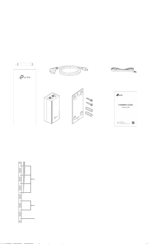
• Package Contents
Power Cord
Pharos CPE
Passive PoE
Adapter
Mounting Bracket
Plastic Wall Anchors (Qty.2)
Self-tapping Screws (Qty.2)
• LED Explanation
The following picture takes CPE220 as an example.
AP/AP Router Mode:
All four LEDs remain solid.
Client/Bridge/Repeater/AP Client Router Mode:
That the more LEDs lit will indicate better wireless signal strength.
On: A device is connected to this port, but there is no activity.
Flashing: A device is connected to this port, and is active.
On: The CPE is powered on.
Pole Mounting
Straps
Installation Guide
01
Page 5
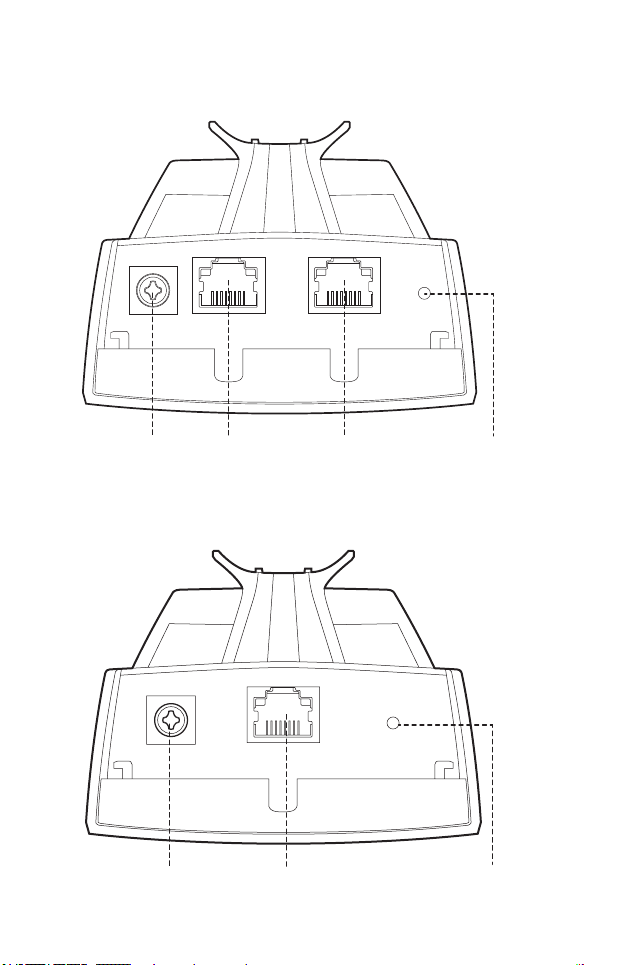
• Panel Layout
Pharos CPE205/CPE220:
Grounding
Terminal
Shielded Ethernet
Port LAN0 (Passive
PoE IN)
Pharos CPE210/CPE510:
Grounding
Terminal
Port LAN1
Shielded Ethernet Port
LAN (Passive PoE IN)
RESETShielded Ethernet
RESET
02
Page 6
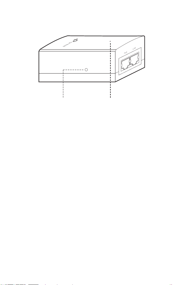
Passive PoE Adapter:
Remote Reset
Press and hold for about 8 seconds
until CPE’s LEDs of wireless signal
strength and LAN ash.
Power LED
The Power LED is on when the
passive PoE adapter is working
normally.
03
Page 7
Hardware Connection
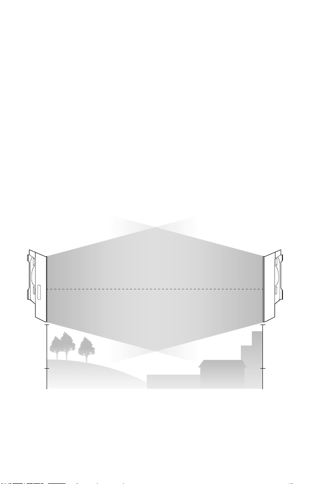
1. Site Consideration
• Mounting Height
Ensure a clear line of sight between the wireless devices for an optimum
performance. An elevated location is recommended as obstacles like
trees, buildings and large steel structures will weaken the wireless signal.
See 'Q2' in 'FAQ' for details about how to calculate the minimum mounting
height of the devices.
Line of Sight
Side View
04
Page 8
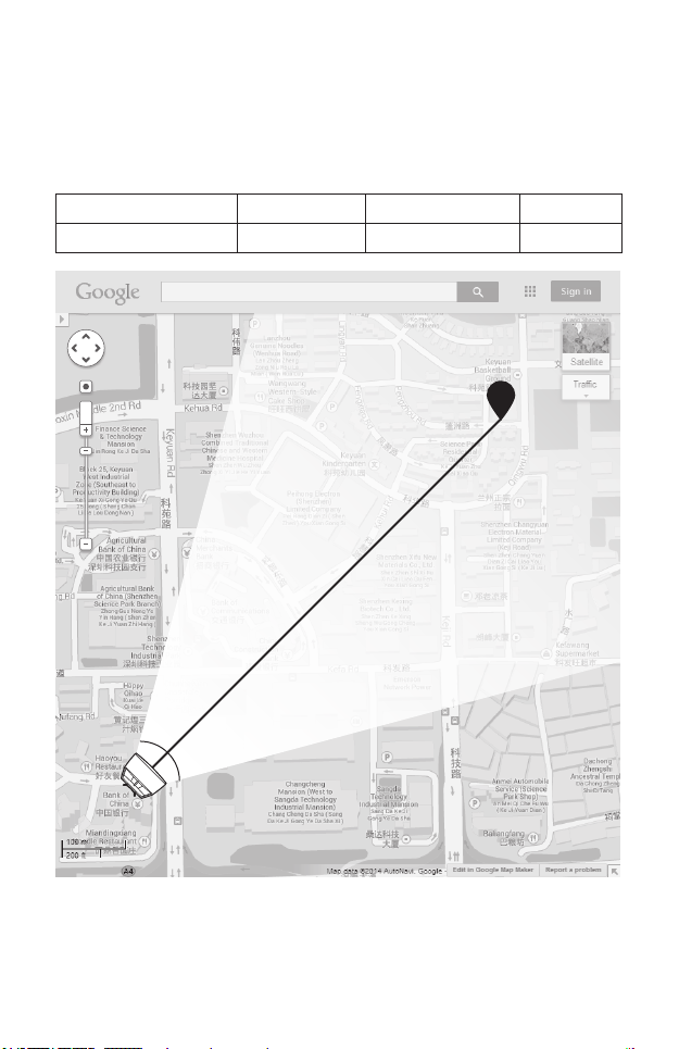
• Orientation
Install the CPE devices with the front facing the intended signal receiving
devices. You can orient the devices with the assistance of Google Maps,
GPS and some landmarks according to the horizontal beamwidth listed
below.
Models CPE210 CPE205/CPE220 CPE510
Horizontal Beamwidth 65° 60° 45°
shenzhen
A
Line of Sight
05
Horizontal
Beamwidth
B
Page 9

2. Connection and Installation
Connect and mount the CPE and power adapter as shown below. The
following introduction takes CPE220 as an example.
• Connecting CPE and Power Adapter
Connect the CPE and power adapter as shown in the gure below.
LAN0
Ethernet cable length up to 60m
Slide to replace the cover
of the CPE when all
connections are nished.
PoE
You should prepare an adequate
Ethernet cable to connect the CPE
and the passive PoE adapter.
Shielded CAT5e (or above) cable
with ground wire is recommended
(refer to the next section).
LAN
Connect to a computer,
router or switch.
(Depending on your
intended usage and/or
network topology.)
06
Page 10

• Mounting CPE
At the selected site, approximately align the CPE to the direction that you
have oriented.
• Mounting Power Adapter (Optional)
Follow the steps below to mount the power adapter:
To ensure the passive PoE adapter is attached most securely, it is
recommended to install the adapter with the Ethernet port facing upward.
1. Drill two holes on the wall and insert the plastic wall anchors into
the holes. Secure the mounting bracket to the wall. Make sure the
shoulders at the corners of the mounting bracket are on the outside
and pointing upward.
2. Attach the passive PoE adapter to the mounting bracket by sliding
the adapter in the direction of the arrows until it locks into place.
07
Page 11

3. Lightning & ESD Protection
Proper grounding is extremely important for outdoor devices.
By using shielded CAT5e (or above) cable with ground wire for the
connection and the provided PoE adapter (method
eliminate ESD attacks. If you use the general CAT5e cable for the
connection, then it is necessary to connect the grounding terminal of the
CPE to earth ground through grounding cable (method
The following introduction takes CPE220 as an example.
1
), you can eectively
2
).
Two Methods:
Shielded CAT5e (or above) Cable
1
with Ground Wire
2
Grounding Terminal and Cable
Grounded 3-wire
Power Outlet
PoE Adapter with
Earth Ground
Grounding
Terminal
Shielded CAT5e (or above)
Cable with Ground Wire
111
Earth Ground
CPE
Grounding
Cable
2
08
Page 12

Sheath
Twisted Pair
Ground Wire
Cable Shield
Secondary Cable Shield
Shielded RJ45 Connector
Shielded CAT5e (or above) Cable with Ground Wire
09
Page 13

Software Conguration
This chapter introduces the login to the PharOS Web Interface and the
software congurations.
1. Logging in to the PharOS
1. Before accessing the PharOS Web Interface, you need to assign
a static IP address 192.168.0.X (X ranges between 2 and 253, e.g.
192.168.0.10) to your computer.
2. Open a web browser, type http://192.168.0.254 into the address eld
and press Enter (Windows) or return (Mac). It is recommended to use
the latest version of Google Chrome, Firefox or Safari.
10
Page 14

3. Enter admin for both User Name and Password. Read and agree the
terms of use, then click Login.
4. Change the default User Name and Password to protect your CPE.
Let’s start conguring the CPE.
For subsequent logins, use the new username and password.
For more congurations, please visit https://www.tp-link.com/support to
download the User Guide of Pharos products in the download center.
11
Page 15

2. Typical Application Conguration
The typical topology is as follows. A wireless bridge is built between two
locations that are far from each other. Follow the instructions below to
congure the Access Point and Client.
IP Camera
Computer
Access Point Client
LAN: 192.168.0.254 LAN: 192.168.0.2
Congure the Access Point (AP)
1. Log in to PharOS and go to the Quick Setup page.
2. Operation Mode: Select Access Point and click Next.
3. LAN Settings: Click Next.
4. Wireless AP Settings:
a. Create a new SSID (Network name) for your wireless network.
b. Select WPA-PSK/WPA2-PSK for the Security method and create
a PSK Password to protect your AP.
c. Enter the distance between the Access Point and the Client into
the Distance Setting eld.
d. Select the MAXtream checkbox (Refer to Q3 in FAQ for details
about MAXtream), and click Next.
5. Finish: Verify your settings and click Finish to complete the
conguration.
Congure the Client
1. Log in to PharOS and go to the Quick Setup page.
2. Operation Mode: Select Client and click Next.
12
Page 16

3. LAN Settings: Change the IP Address to 192.168.0.X (X ranges
between 2 and 253), the same subnet with the Access Point, and
click Next.
4. Wireless Client Settings:
a. Click Survey and select the SSID of the Access Point in the AP list,
then click Connect.
b. Select WPA-PSK/WPA2-PSK from the Security option, enter the
same PSK password and distance value of the Access Point, then
click Next.
5. Finish: Verify your settings and click Finish to complete the
conguration.
For more congurations, please visit https://www.tp-link.com/support to
download the User Guide of Pharos products in the download center.
13
Page 17

Antenna Alignment
Antenna alignment can help you to optimize the antenna signal. To get the
best wireless performance, click Antenna Alignment from the drop-down
list on the upper-right corner and enable Alignment Beep during alignment. Then adjust your antenna until the sound frequency turns to the
lowest.
Check the box to enable the beep sound. Its frequency
can help you to estimate the signal strength received by
the antenna. The lower the sound frequency, the stronger
the signal strength.
WISP
WISP
14
Page 18

Specications
HARDWARE FEATURES
Models CPE210/CPE510 CPE205/CPE220
Dimensions 224 × 79 × 60 mm 276 × 79 × 60 mm
LAN: 10/100 Mbps
Ethernet Port (PoE IN)
Interface
GND: Grounding Terminal for Lightning Protection
RESET: To restore the device to Factory Default
Passive PoE Adapter Included
Power Supply
ESD Protection
Lightning Protection
Operating
Temperature
Operating Humidity 10% to 90%
Certication
WIRELESS FEATURES
Models CPE210 CPE205/CPE220 CPE510
Antenna Gain 9 dBi 12 dBi 13 dBi
Horizontal
Beamwidth/Elevation
Beamwidth
802.11 Standards 11b/g/n 11b/g/n 11a/n
Note:
1. Estimation is based on copper grounding cable and shielded CAT5e cable
with ground wire.
2. Beamwidth values may vary throughout operating frequency.
15
2
CPE205/CPE210: 24 VDC/0.25 A
CPE220/CPE510: 24 VDC/0.5 A
1
15 kV
1
Up to 6 kV
-40 ℃ to 70 ℃ (-40 ℉to 158 ℉)
CPE210/CPE220/CPE510: CE, FCC, RoHS, IPX5
CPE205: RoHS, IPX5
65°/40° 60°/30° 45°/45°
LAN0: 10/100 Mbps
Ethernet Port (PoE IN)
LAN1: 10/100 Mbps
Ethernet Port
Page 19

FAQ
Q1. How to restore the CPE to its factory default
settings?
With the CPE powered on, you can reset the CPE via either the
RESET button on the CPE or the Remote Reset button on the
Passive PoE Adapter.
Method 1: Via the RESET Button on the CPE
The following picture takes CPE220 as an example.
RESET Button
Press and hold for about 8 seconds
until CPE’s LEDs of wireless signal
strength and LAN ash.
Method 2: Via the Remote Reset Button on the Passive PoE
Adapter
Remote Reset Button
Press and hold for about 8 seconds until CPE’s
LEDs of wireless signal strength and LAN ash.
16
Page 20

Q2. How to calculate the minimum mounting height
of the devices?
In order to maximize the received signal strength of the devices,
installers need to minimize the effect of the out-of-phase signals,
which is caused by obstacles in the path between the transmitter
and the receiver. Fresnel Zone is a usual method to calculate this
path, as shown in the formula and the gure below.
d
2
d
1
r
H h+r*(1 40%)
(H is the height of the CPE)
h = the height of
obstacle at this point
where,
r = Fresnel zone radius in meters
8
m/s, speed of light
c = 3x10
f = operating frequency of the devices in
Hz
& d2 = the distances between the
d
1
point and the devices in meters
For example, assume d1 is 2 km, d2 is 8 km, and f is 2.4 GHz, then
r would be 14.142 m. Considering a toleration of 40%, allowable
radius would be 8.485 m. Assume h is 10 m, then the result of the
minimum mounting height based on this point would be 18.485 m.
Similarly, calculate the results based on all the points where there are
obstacles, and the maximum value would be the nal result.
For more information, please refer to:
https://en.wikipedia.org/wiki/Fresnel_zone
17
Page 21

Q3. What is Pharos MAXtream?
Pharos MAXtream is a proprietary protocol developed on the basis
of Time Division Multiple Access (TDMA) by TP-Link.
The MAXtream technology has the following advantages:
• Eliminates hidden node collisions and improves channel eciency.
• Lower latency, higher throughput, larger network capacity and
more stability.
• Improves the QoS for video, voice and sound data stream.
By dividing the timing of transmission into different time slots,
MAXtream allows the Pharos devices to transmit in rapid succession,
one after another, each using its own time slot to transmit and
receive their own frames, which greatly reduces the chance of
collision.
Pharos MAXtream is a non-standard Wi-Fi protocol that is only
compatible with TP-Link’s Pharos series products. Please notice
that you will not be able to connect other Wi-Fi devices to an AP with
MAXtream enabled.
Q4. How can I use Spectrum Analysis to nd the
appropriate channel for the devices?
1. Log in to PharOS, click Spectrum Analysis in the tools drop-down
list, a window will pop up to remind you that all wireless connections
will be lost during spectrum analysis. Click Yes to continue to the
Spectrum Analysis page.
2. Click Start, the Pharos will begin to analyze the power of frequency.
Observe the curves for a period of time, and then click Stop. Note
that the relatively low and continuous part of the average curve
18
Page 22

indicates less radio noise. Here, we use the figure below as an
example.
The select box of Frequency Range at the top-left corner is only
available for CPE510. Select the desired range and then click Start.
When choosing channel/frequency, you should avoid the spectrum
with large radio noise. In this example, the recommended channel/
frequency is 112/5560 MHz.
Note: To ask questions, nd answers, and communicate with TP-Link users
or engineers, please visit https://community.tp-link.com to join TP-Link
Community.
19
Page 23

Safety Information
• Keep the device away from re or hot environments. DO NOT immerse in water or any
other liquid.
• Do not attempt to disassemble, repair, or modify the device. If you need service, please
contact us.
• Do not use damaged charger or USB cable to charge the device.
• Do not use any other chargers than those recommended
• Do not use the device where wireless devices are not allowed.
• Adapter shall be installed near the equipment and shall be easily accessible.
Use only power supplies which are provided by manufacturer and in the original
packing of this product. If you have any questions, please don't hesitate to contact us.
Please read and follow the above safety information when operating the device. We
cannot guarantee that no accidents or damage will occur due to improper use of the
device. Please use this product with care and operate at your own risk.
Продукт сертифіковано згідно с правилами системи УкрСЕПРО на відповідність
вимогам нормативних документів та вимогам, що передбачені чинними
законодавчими актами України.
Page 24

To ask ques tions, f ind answe rs, and com municat e with TP-L ink users o r enginee rs,
please visit https://community.tp-link.com to join TP- Link Com munity.
For tec hnical su pport, t he user gui de and othe r informa tion, ple ase visi t
https://www.tp-link.com/support, or s imply sca n the QR code .
If you ha ve any sugge stions or n eeds on the p roduct gu ides, wel come to emai l
techwriter@tp-link.com.cn.
The pro ducts of TP- Link par tly cont ain soft ware code dev eloped by th ird part ies, inclu ding sof tware cod e subject
to th e GNU G eneral Public L icense (“GPL”). As applic able, t he term s of the GPL and any in formati on on ob taining
acces s to the resp ective G PL Code use d in TP-Li nk produc ts are avai lable to yo u in GPL-Code -Centr e under
(htt ps://w ww.tp-l ink.co m/en/sup port/g pl/). The resp ective program s are di stribu ted WIT HOUT AN Y WARRA NTY
and a re subj ect to t he copy rights of one or more authors . For d etails, see th e GPL C ode and other t erms of the
GPL.
©2020 TP-Link
7106508846 REV3.3.0
 Loading...