

Toyota TVSS IV-D Installation Instructions Manual
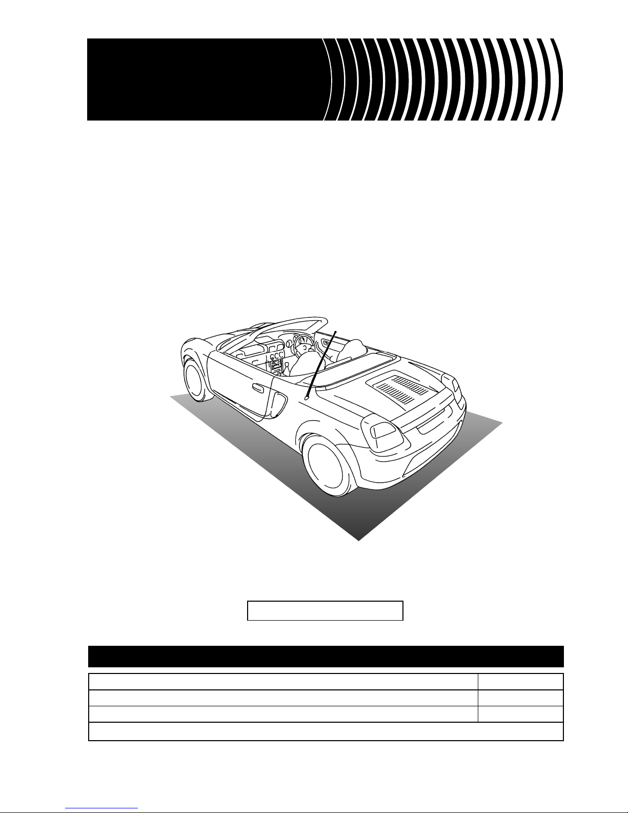
MR2 (RHD)
TOYOTA MOTOR CORPORATION
INSTALLATION INSTRUCTIONS
for
PART NUMBER
MAIN KIT 08585-12950
FITTING KIT 08586-17890
SUB KIT ( SIREN AND RADAR) 08586-1A890
FOR
**W3*
R
Manual Ref. Nr. T4RW3-0-400
ALARM
TOYOTA VEHICLE SECURITY SYSTEM
TT VVSS SS II VV -- DD
PRELIMINARY
02-00
PRECAUTIONS
MR2 (RHD) - 2
MR2 (W3) TVSS IV-D
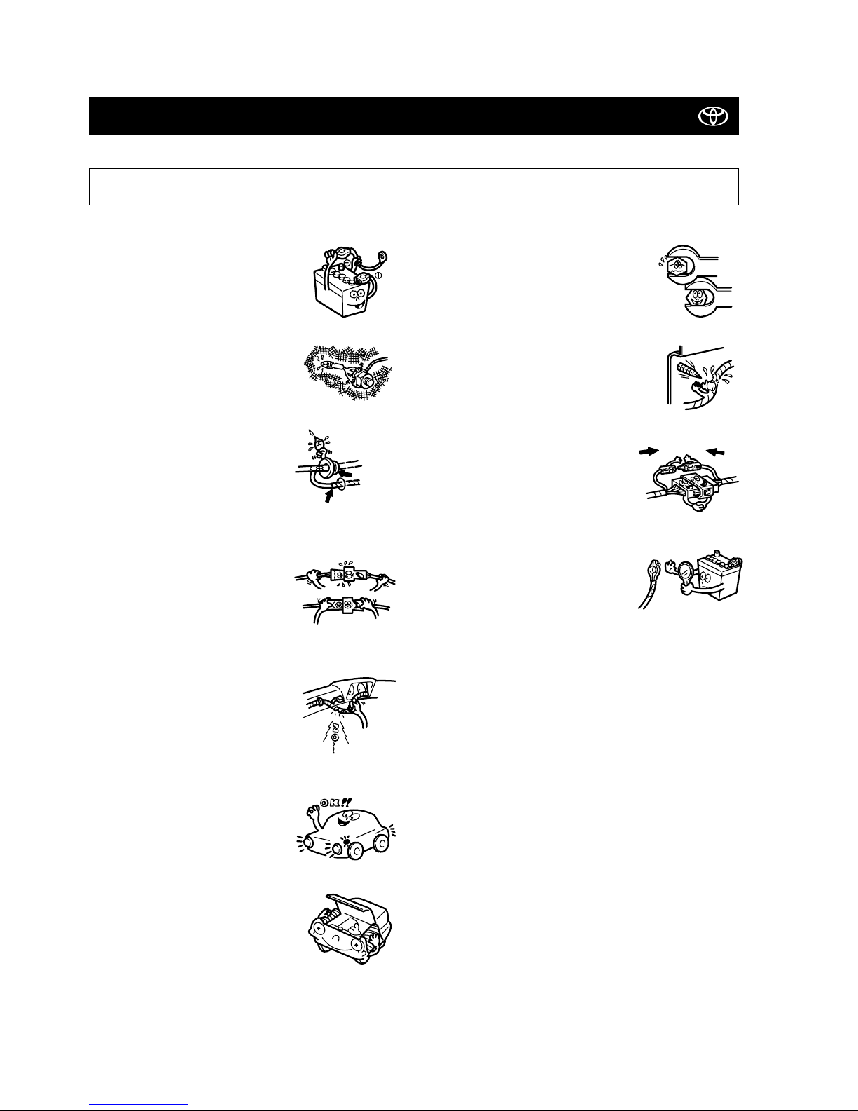
PLEASE READ THOROUGHLY THESE PRECAUTIONS
BEFORE THE TVSS INSTALLATION
• Be sure to disconnect the negative (-)
lead from the battery terminals.
• Do not pinch the rear wiring or harness
in the tightened part.
• When passing the wires through the
bulkhead or other panels, use a
grommet to ensure waterproofing.
• Protect the wiring with tape when it is
passed through a hole.
• When disconnecting the connectors,
be sure to grip the connector body. Do
not tug on the wiring.
• Do not forcibly pull any car wiring harness. Rough tugging may result in opened connections, or a broken wire or
harness.
• Confirm that lamps, horn, wiper and other car accessories operate normally.
• Protect your car with wing covers, seat
and so on.
• Use the correct tool when tightening
bolts or nuts.
• Before drilling a hole, check that the rear
of the mounting wall is clear.
• Be sure to firmly tighten connectors and
terminals.
• Before connecting the power wiring to
the battery, check the wiring connections, harness, etc. to see that they
are properly secured.
• Check body and trim near area of installation to be certain no
dirt or scratches resulted from the installation.
waterproof - O.K. !!
Grommet
Stop it !
Taping
Insert completely

02-00
TABLE OF CONTENTS
MR2 (RHD) - 3
MR2 (W3) TVSS IV-D
Precautions ................................................................................................................................................................ 2
System Components
• Fitting Kit ........................................................................................................................................................... 4
• Main Kit ............................................................................................................................................................. 6
• Sub Kit ............................................................................................................................................................... 6
System Layout and Wire Harness Outline (main) ..................................................................................... 7
System Layout and Wire Harness Outline (bonnet) ................................................................................. 8
System Layout and Wire Harness Outline (engine) ................................................................................. 9
Connector Arrangement of the TVSS Fitting Kit (Pin View)
................................................................. 10
TVSS Installation Instructions
• Vehicle Disassembly .......................................................................................................................................... 11
• Wire Harness Installation Part 1 (Main) ............................................................................................................. 15
• Mounting the Status Monitor ............................................................................................................................. 21
• Wire Harness Installation Part 2 (Main) ............................................................................................................. 22
• Mounting the Radar Sensor ............................................................................................................................... 23
• Vehicle Disassembly (Boot) ............................................................................................................................... 25
• Drilling the Holes ............................................................................................................................................... 27
• Wire Harness Installation (Boot) ........................................................................................................................ 28
• Mounting the Siren ............................................................................................................................................ 31
• Mounting the Hood Switch (Boot) ..................................................................................................................... 32
• Vehicle Disassembly (Engine) ............................................................................................................................ 33
• Wire Harness Installation (Engine) .................................................................................................................... 34
• Mounting the Hood Switch (Engine) .................................................................................................................. 35
• Mounting the TVSS ECU .................................................................................................................................... 36
• Attaching the Stickers ........................................................................................................................................ 38
02-00
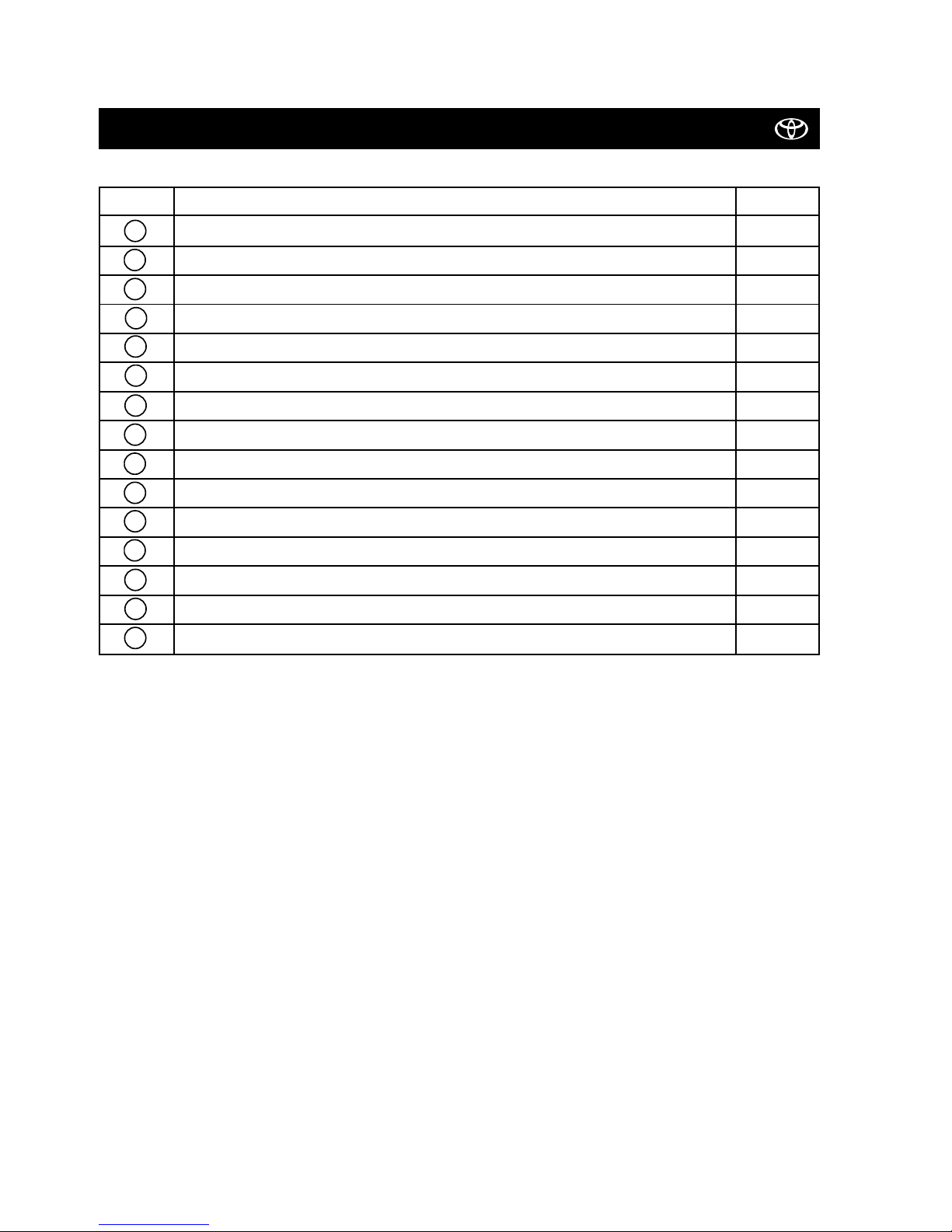
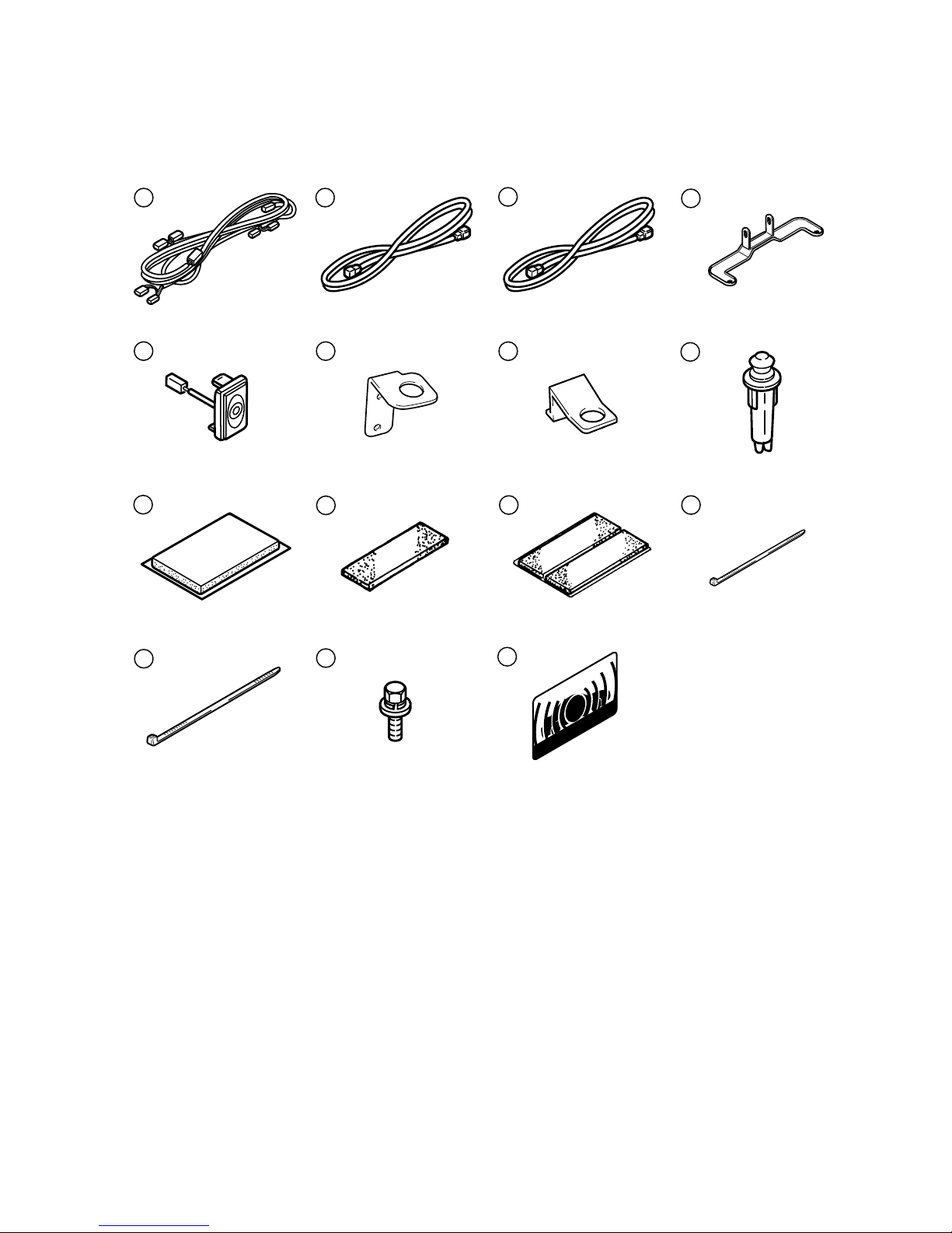
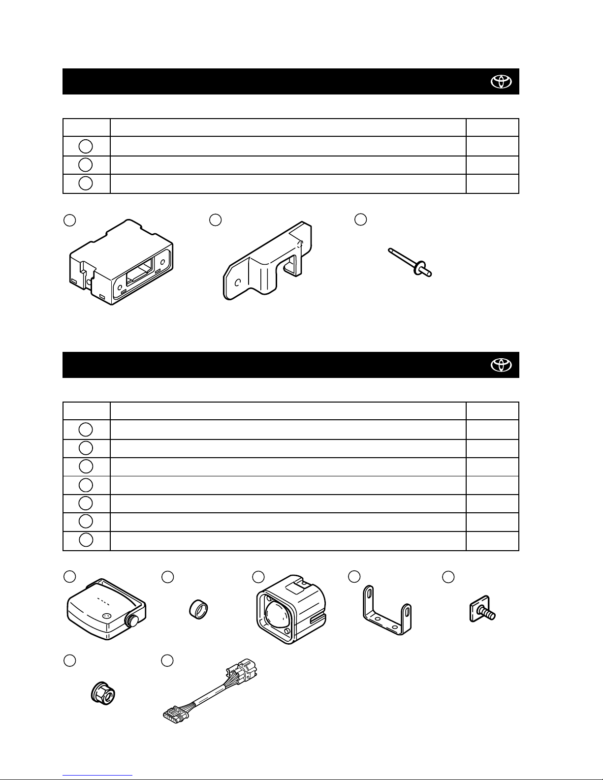
FITTING KIT 08586-17890
MR2 (RHD) - 4
MR2 (W3) TVSS IV-D
Pos. No. Description Qty
TVSS WIRE HARNESS (MAIN) 1
TVSS WIRE HARNESS (BOOT) 1
TVSS WIRE HARNESS (ENGINE) 1
SIREN BRACKET 1
STATUS MONITOR 1
HOOD SWITCH BRACKET (BOOT) 1
HOOD SWITCH BRACKET (ENGINE) 1
HOOD SWITCH 2
BUTYL TAPE 3
FOAM (1 DIVISION ON 1 SHEET) 1
FOAM (2 DIVISIONS ON 1 SHEET) 1
WIRE TIE (150mm) 25
WIRE TIE (200mm) 5
BOLT 3
WINDOW STICKERS 2
15
14
13
12
11
1098
7
6
5
4
3
2
1
02-00
MR2 (RHD) - 5
MR2 (W3) TVSS IV-D
6
7
8
10
9
11 12
14
AT TO OY
15
13
21
3
4
5
02-00
MR2 (RHD) - 6
MR2 (W3) TVSS IV-D
MAIN KIT 08585-12950
Pos. No. Description Qty
TVSS ECU 1
ECU PROTECTIVE BRACKET 1
BLIND RIVET 2
III
II
I
SUB KIT (RADAR AND SIREN) 08586-1A890
Pos. No. Description Qty
RADAR SENSOR 1
CAP 2
SIREN 1
SIREN BRACKET 1
BOLT 2
NUT 2
SIREN WIRE HARNESS 1
vii
vi
v
iv
iiiiii
ii
i
iii
iv
v
vi
vii
II
I
III
02-00
MR2 (RHD) - 7
MR2 (W3) TVSS IV-D
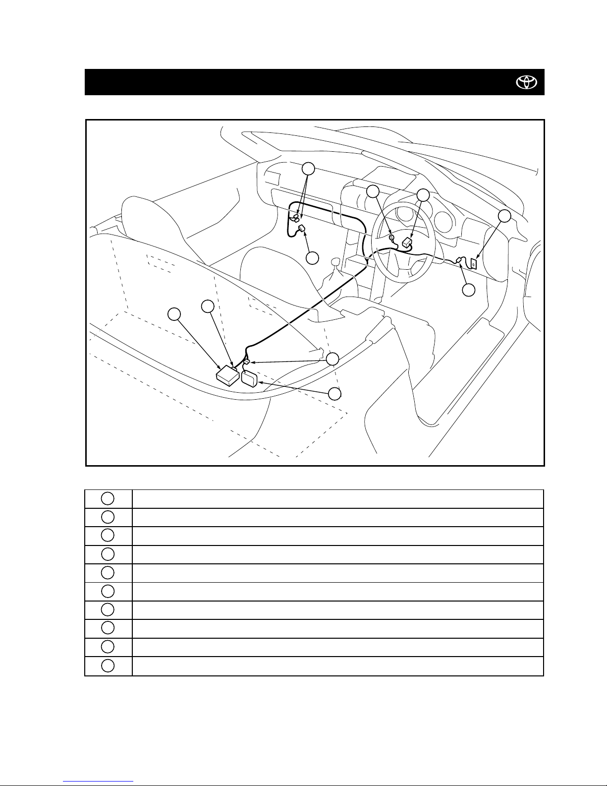
SYSTEM LAYOUT AND WIRE HARNESS OUTLINE (MAIN)
TVSS ECU
TVSS ECU connector (26P female grey)
Pre-wired connector (3P male white)
Pre-wired connector (1P female and male white)
Ground terminal
Pre-wired connector (11P male white)
Status monitor connector (2P female clear)
Status monitor
Radar sensor connector (4P female)
Radar sensor
J
I
H
G
FEDCB
A
G
F
ECD
A
B
H
J
I

02-00
MR2 (RHD) - 8
MR2 (W3) TVSS IV-D
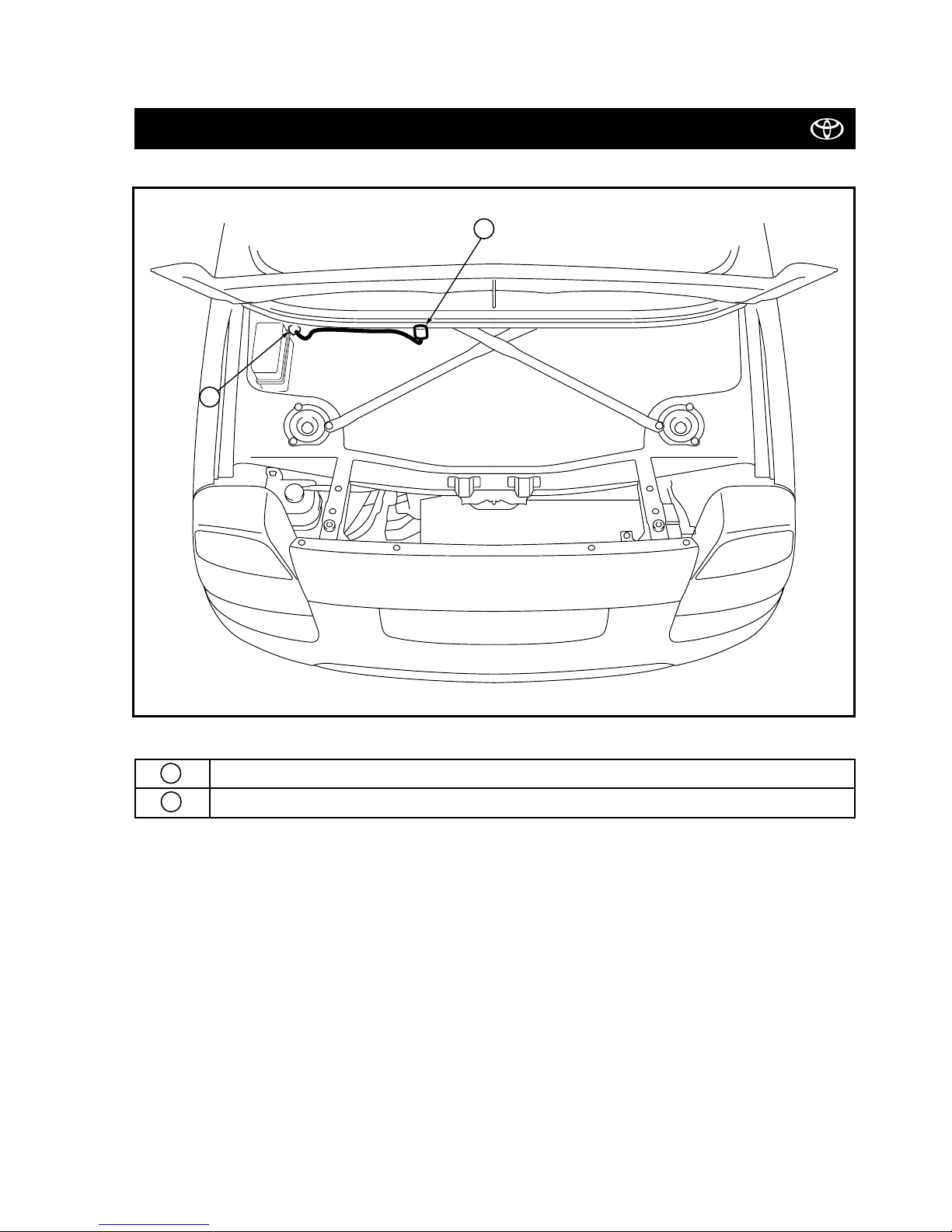
SYSTEM LAYOUT AND WIRE HARNESS OUTLINE (BONNET)
Pre-wired connector (6P male grey)
Siren Connector (6P female grey)
Hood switch connector (2P female white)
Siren
d
cba
c
a
b
d
02-00
MR2 (RHD) - 9
MR2 (W3) TVSS IV-D
SYSTEM LAYOUT AND WIRE HARNESS OUTLINE (ENGINE)
Pre-wired connector (2P male grey)
Hood switch connector (2P female white)
fef
e
MR2 (RHD) - 10
MR2 (W3) TVSS IV-D
02-00
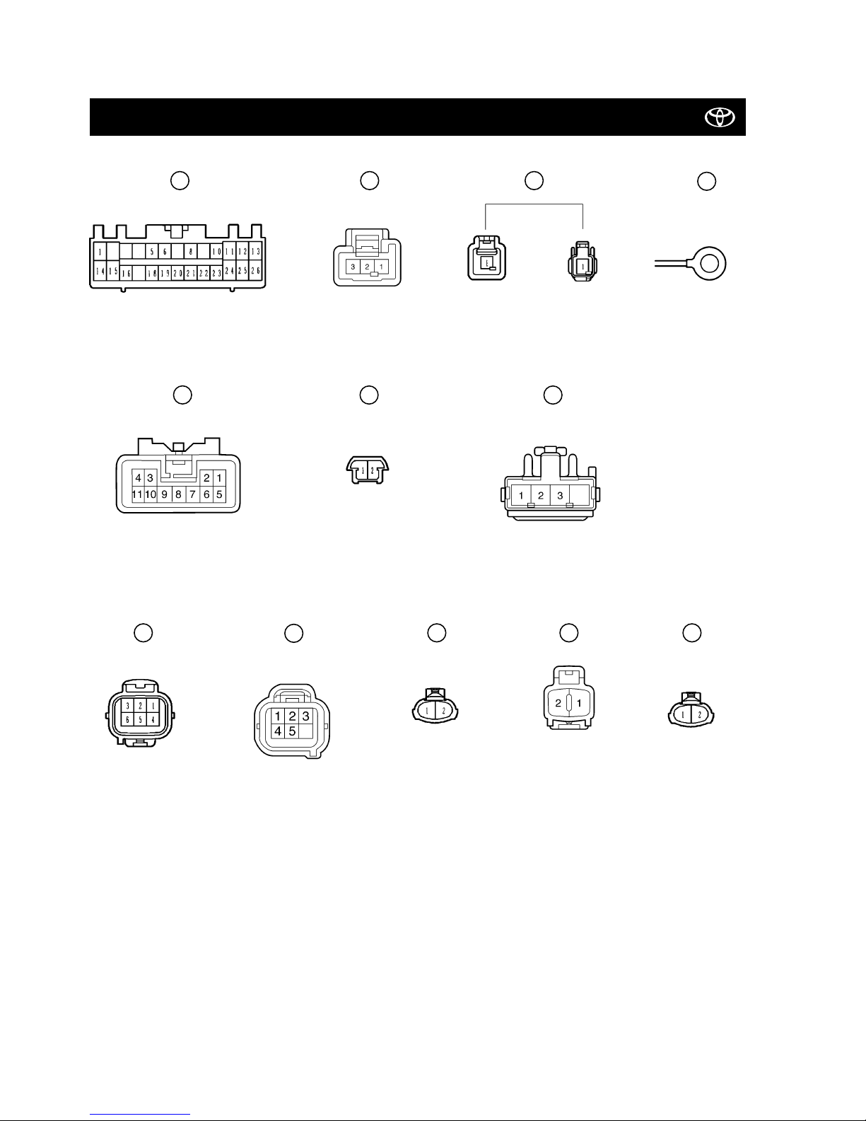
CONNECTOR ARRANGEMENT OF THE TVSS (PIN VIEW)
B C D
E
F
G
I
a
b
c
e
f
Male pin
Male pin
Male pin
Male pin
Male pinFemale pin
Female pin
Female pin
Female pin Female pin
Female pin
Female pin Ground terminal
MR2 (RHD) - 11
MR2 (W3) TVSS IV-D
02-00
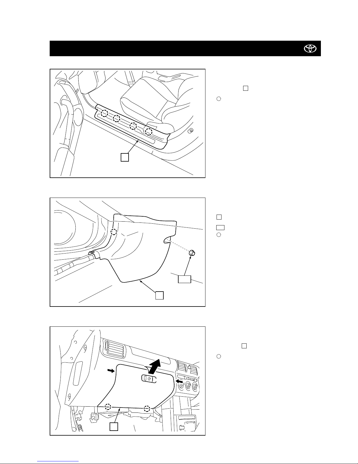
Figure 1
VEHICLE DISASSEMBLY
2.
Remove the passenger’s side kick panel
.
: Retainer (1x)
: Clip (1x)
100
2
3.
Remove the glove compartment door
assembly .
: Clip (2x)
3
1.
Remove the passenger’s side front door
scuff plate .
: Clip (4x)
1
Figure 2
Figure 3
1
2
100
3
02-00
MR2 (RHD) - 12
MR2 (W3) TVSS IV-D
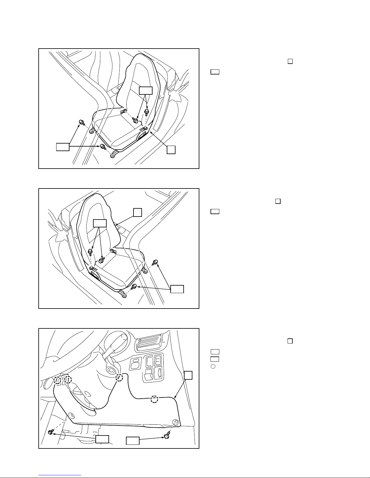
4.
Remove the passenger’s seat .
: Bolt (4x)
114
4
5.
Remove the driver’s seat .
: Bolt (4x)
114
5
6.
Remove the underdash cover .
: Bolt (1x)
: Screw (1x)
: Clip (4x)
102
103
6
Figure 4
Figure 5
Figure 6
4
5
114
114
114
6
103
102
114
 Loading...