

Toyota TVSS IIIB Installation Instructions Manual
TOYOTA MOTOR CORPORATION
Manual Ref. Nr. T3RL5-0-500
LAND CRUISER 80 (RHD)
VEHICLE SECURITY SYSTEM
TVSS IIIB
INSTALLATION INSTRUCTIONS
PART NUMBER
MAIN KIT 08585-00880
SUB KIT (SIREN AND RADAR) 08586-50820
FITTING KIT 08586-60950
FOR FZJ80R, HDJ80R, HZJ80R
TOYOTA MOTOR CORPORATION
Manual Ref. Nr. T3RJ8-0-500
PRECAUTIONS
Land Cruiser 80 (RHD) - 2
Land Cruiser 80 TOYOTA TVSS IIIB
Precautions
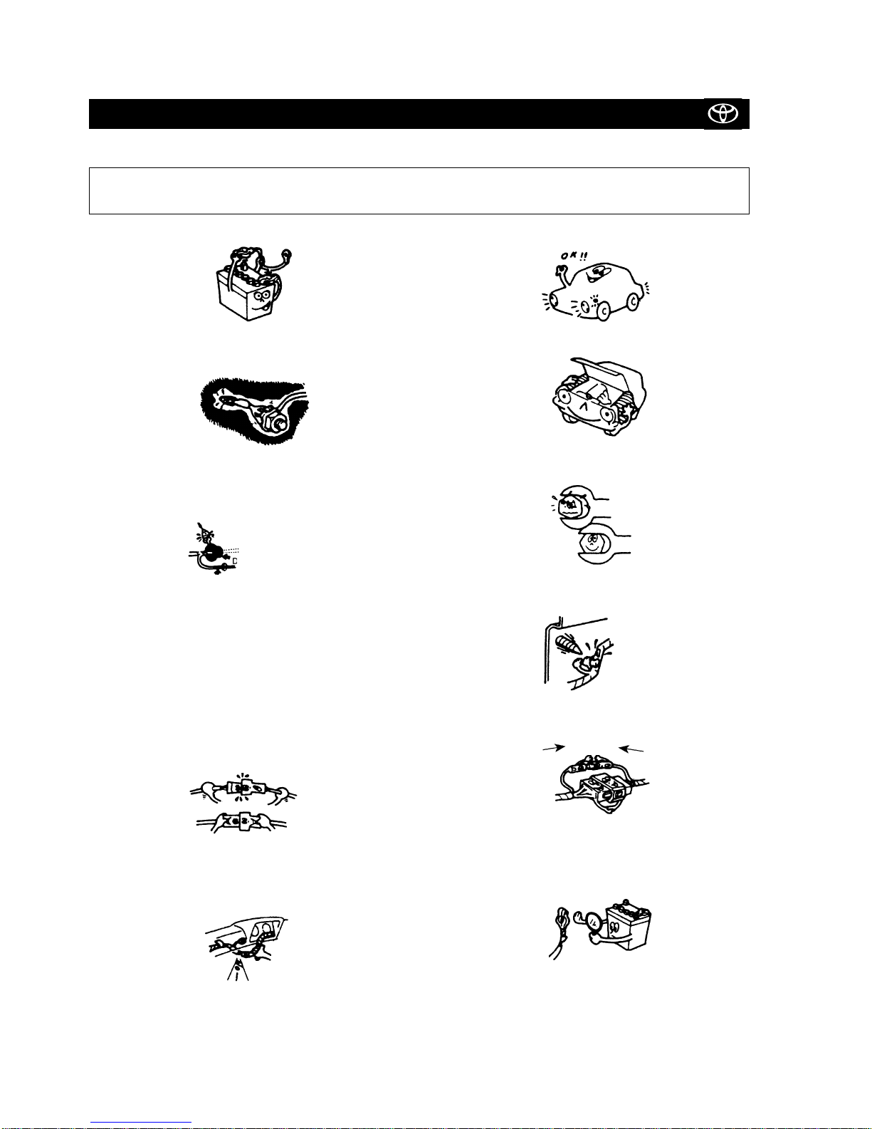
PLEASE READ THOROUGHLY THESE PRECAUTIONS
FOR THIS SYSTEM INSTALLATION
• Be sure to disconnect the negative (-) lead from the battery terminals.
• Do not pinch the rear wiring or harness in the tightened part.
• When passing the wires through the bulkhead or other panels,
use a grommet to ensure waterproofing.
• Protect the wiring with tape when it is passed through a hole.
• When disconnecting the connectors, be sure to grip the connector body. Do not tug on the wiring.
• Do not forcibly pull any car wiring harness. Rough tugging may
result in opened connections, or a broken wire or harness.
• Confirm that lamps, horn, wiper and other car accessories operate
normally.
• Protect your car with wing covers, seat and so on.
• Use the correct tool when tightening bolts or nuts.
• Before drilling a hole, check that the rear of the mounting wall
is clear.
• Be sure to firmly tighten connectors and terminals.
• Before connecting the power wiring to the battery, check the
wiring connections, harness, etc. to see that they are properly
secured.
• Check body and trim near area of installation to be certain no
dirt or scratches resulted from the installation.
waterproof - O.K. !!
Taping
Grommet
Insert
completely
Stop it !

TABLE OF CONTENTS
Land Cruiser 80 (RHD) - 3
Land Cruiser 80 TOYOTA TVSS IIIB
Table of Contents
Precautions ................................................................................................................................................................... 2
System Components
• Main Kit ............................................................................................................................................................... 4
• Sub Kit (Siren and Radar) ................................................................................................................................... 4
• Fitting Kit ............................................................................................................................................................. 5
System Layout and Wire Harness Outline
• Main .................................................................................................................................................................... 7
• Engine ................................................................................................................................................................. 8
Connector Arrangement of the TVSS Fitting Kit (Pin View) ............................................................................ 9
TVSS Installation Procedures
• Vehicle Disassembly (Passenger Compartment) ................................................................................................ 10
• Wire Harness (Main) Installation ........................................................................................................................ 13
• Mounting the Status Monitor .............................................................................................................................. 15
• Mounting the Radar Sensor ................................................................................................................................ 16
• Mounting the Glass Breakage Control Unit ......................................................................................................... 18
• Vehicle Disassembly (Engine Compartment) ...................................................................................................... 20
• Mounting the Siren ............................................................................................................................................. 23
• Wire Harness (Engine) Installation ...................................................................................................................... 25
• Mounting the Hood Switch ................................................................................................................................. 28
• Setting the TVSS ECU Dip Switches and Testing the System ............................................................................. 29
• Mounting the TVSS ECU ..................................................................................................................................... 30
• Mounting the Glass Breakage Sensor ................................................................................................................. 32
• Attaching the Stickers ......................................................................................................................................... 34
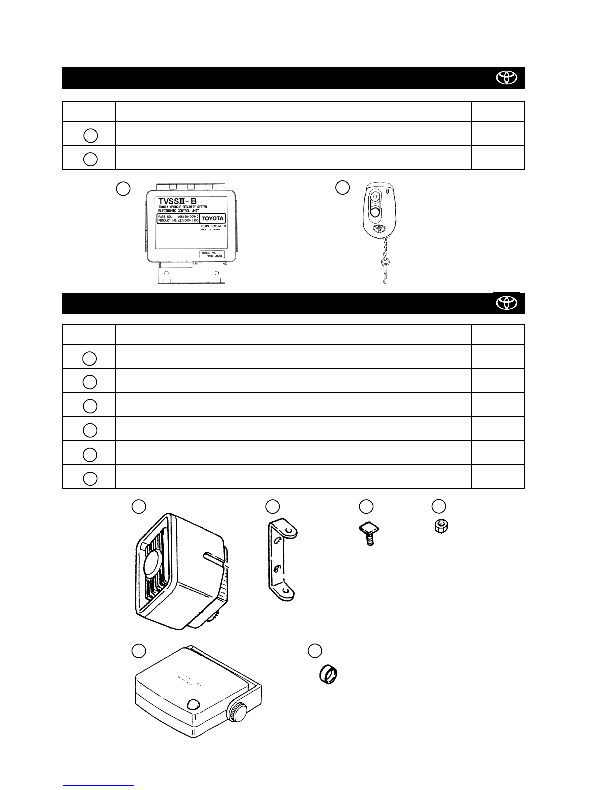
SUB KIT (SIREN AND RADAR) 08586-50820
MAIN KIT 08585-00880
Land Cruiser (RHD) - 4
Land Cruiser 80 TOYOTA TVSS IIIB
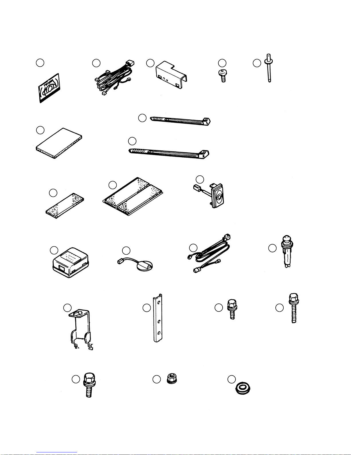
Main Kit - Sub Kit (Siren and Radar)
No. Description Qty
TVSS ECU 1
REMOTE CONTROL TRANSMITTER 2
II
I
No. Description Qty
SIREN 1
SIREN BRACKET 1
BOLT 2
NUT 2
RADAR SENSOR 1
CAP 2
IV
III
iv
iii
ii
i
I
iIIii
iii
iv
III
IV
Other parts in the kit are not used.
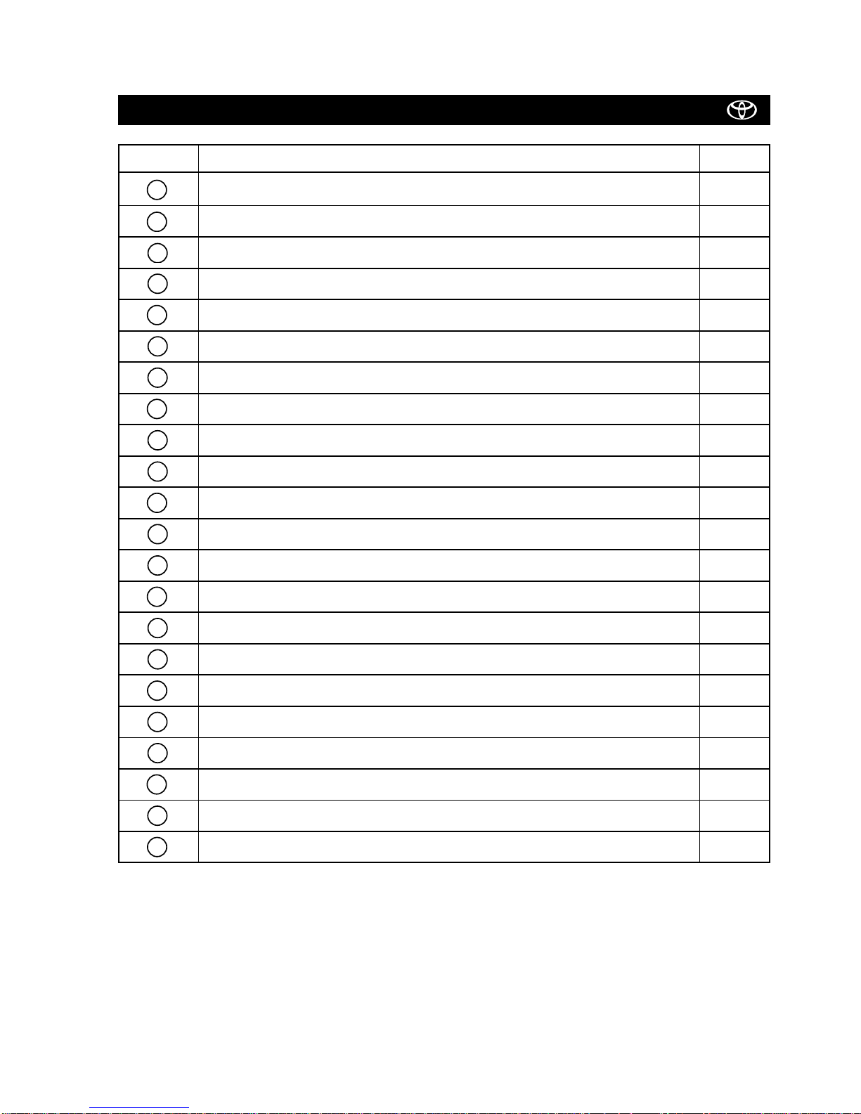
FITTING KIT 08586-60950
Land Cruiser 80 (RHD) - 5
Land Cruiser 80 TOYOTA TVSS IIIB
Fitting Kit
No. Description Qty
WINDOW STICKER 2
WIRE HARNESS (MAIN) 1
PROTECTIVE BRACKET 1
SCREW 1
BLIND RIVET 1
BUTYL TAPE 1
WIRE TIE (SMALL) 10
WIRE TIE (LARGE) 4
FOAM (1 DIVISION ON 1 SHEET) 1
FOAM (2 DIVISIONS ON 1 SHEET) 2
STATUS MONITOR 1
GLASS BREAKAGE CONTROL UNIT
1
GLASS BREAKAGE SENSOR
1
WIRE HARNESS (ENGINE) 1
HOOD SWITCH 1
HOOD SWITCH BRACKET 1
MOUNTING BRACKET (FOR SIREN) 1
BOLT (M6 X 18MM) (FOR SIREN) 1
BOLT (M6 X 30MM) (FOR SIREN) 2
BOLT (M8 X 20MM) (FOR HOOD SWITCH) 1
NUT (M6) 3
WASHER 2
222120
19
18
1716151413
12111098
7
654
3
2
1
245
6
7
8
Fitting Kit
Land Cruiser 80 TOYOTA TVSS IIIB
Land Cruiser 80 (RHD) - 6
3
1
9
101112
1314151617
18
19
20
21
22
SYSTEM LAYOUT AND WIRE HARNESS OUTLINE (MAIN)
Land Cruiser 80 (RHD) - 7
Land Cruiser 80 TOYOTA TVSS IIIB
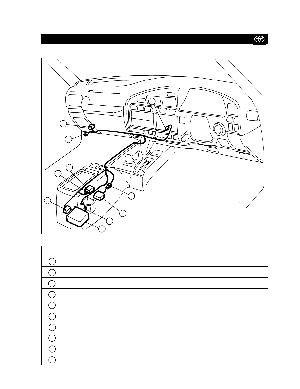
System Layout and Wire Harness Outline (Main)
Pos. No. Description
TVSS ECU
TVSS ECU CONNECTOR (26P GREY)
GROUND TERMINAL
PRE-WIRE CONNECTOR (12P WHITE)
STATUS MONITOR CONNECTOR (2P CLEAR)
RADAR SENSOR CONNECTOR (4P WHITE)
GLASS BREAKAGE CONTROL CONNECTOR (6P WHITE)
GLASS BREAKAGE SENSOR CONNECTOR (2P WHITE)
GLASS BREAKAGE CONTROL UNIT
RADAR SENSOR
K
J
H
G
F
E
D
C
B
A
ABC
E
D
G
H
J
K
F
Land Cruiser 80 (RHD) - 8
Land Cruiser 80 TOYOTA TVSS IIIB
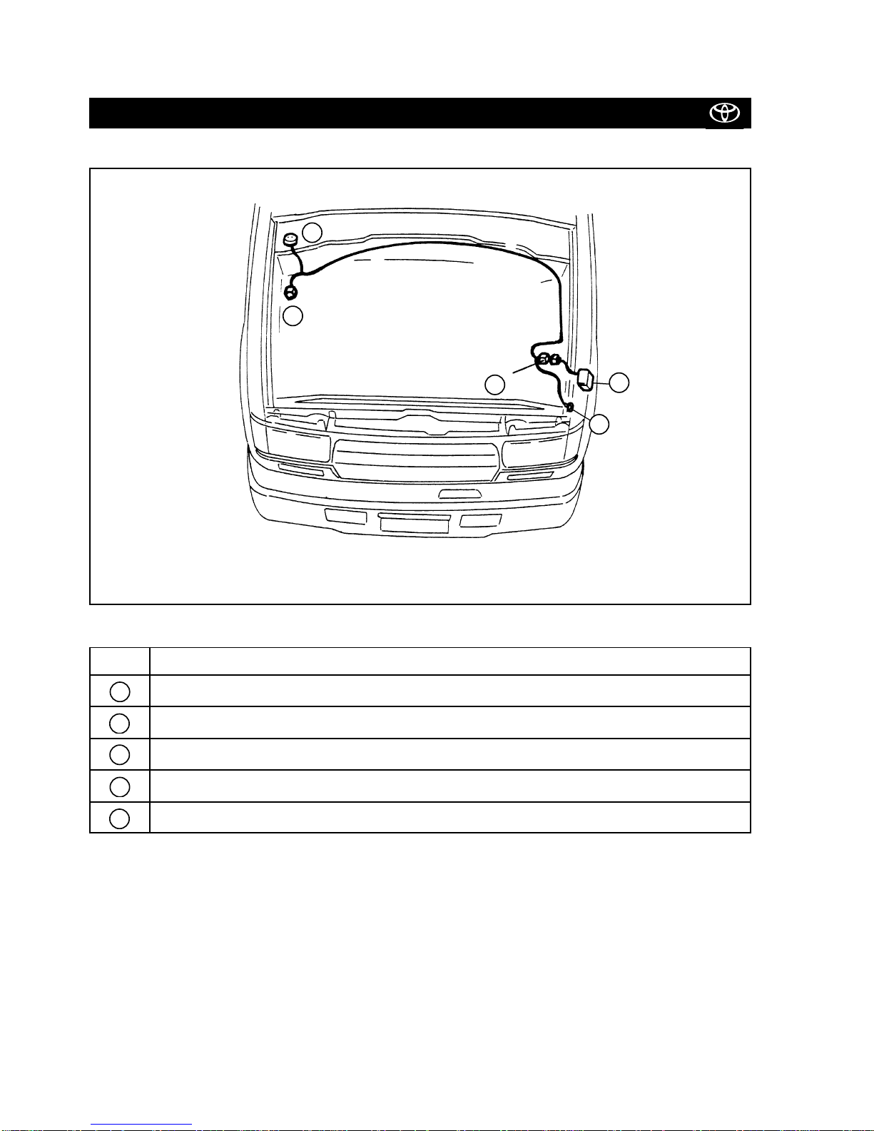
System Layout and Wire Harness Outline (Engine)
SYSTEM LAYOUT AND WIRE HARNESS OUTLINE (ENGINE)
Pos. No. Description
PRE-WIRE CONNECTOR (6P GREY MALE)
SIREN CONNECTORS (6P GREY FEMALE)
GROUND TERMINAL
HOOD SWITCH CONNECTOR (2P WHITE)
SIREN
e
d
c
b
a
a
d
b
c
e
Land Cruiser 80 (RHD) - 9
B
EDF
a
b
(female pin)
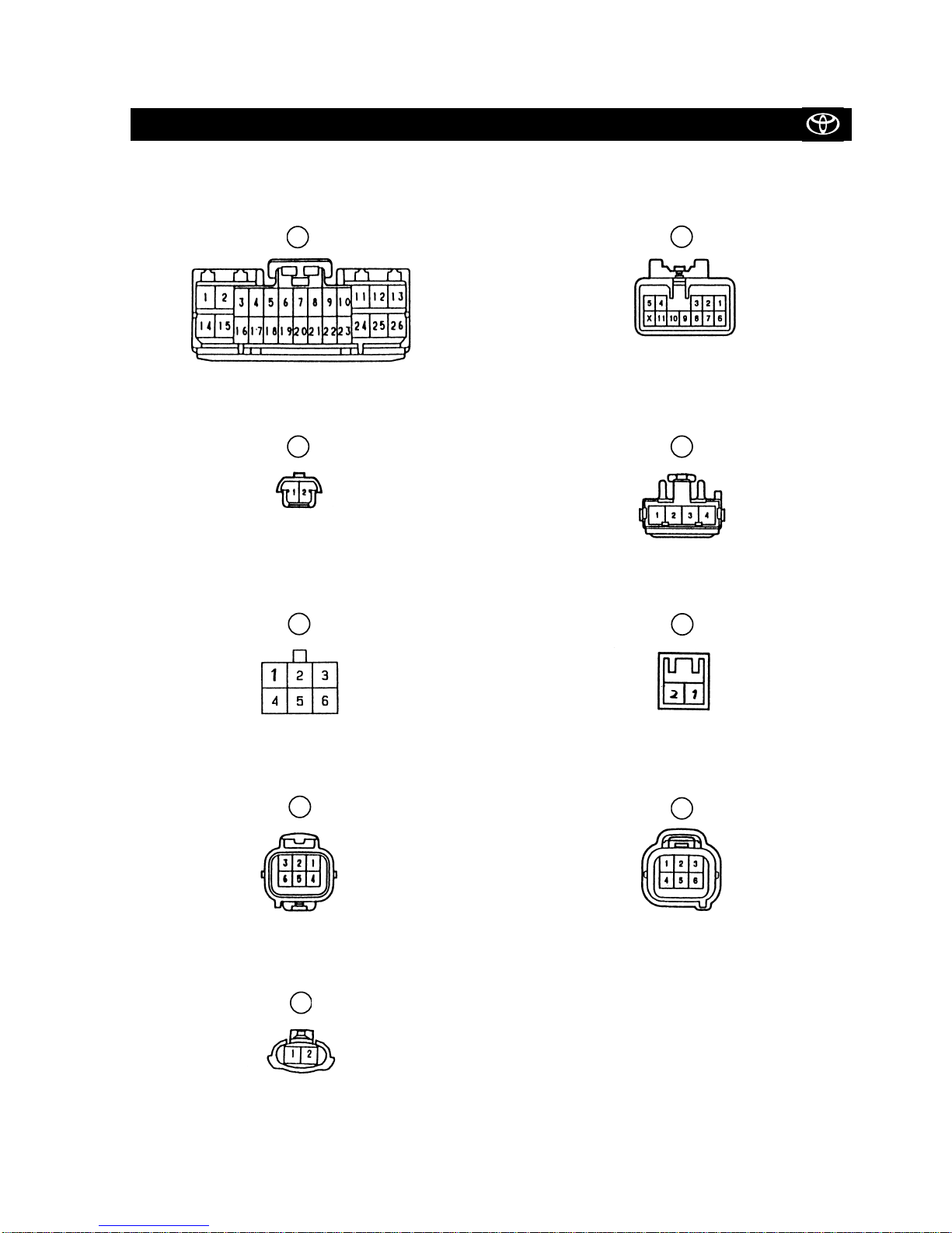
CONNECTOR ARRANGEMENT OF THE TVSS FITTING KIT (PIN VIEW)
Land Cruiser 80 TOYOTA TVSS IIIB
Connector Arrangement of the TVSS Fitting Kit (Pin View)
(male pin)
(female pin)
(female pin)
(female pin)
(male pin)
d
(female pin)
G
H
(female pin)
(male pin)
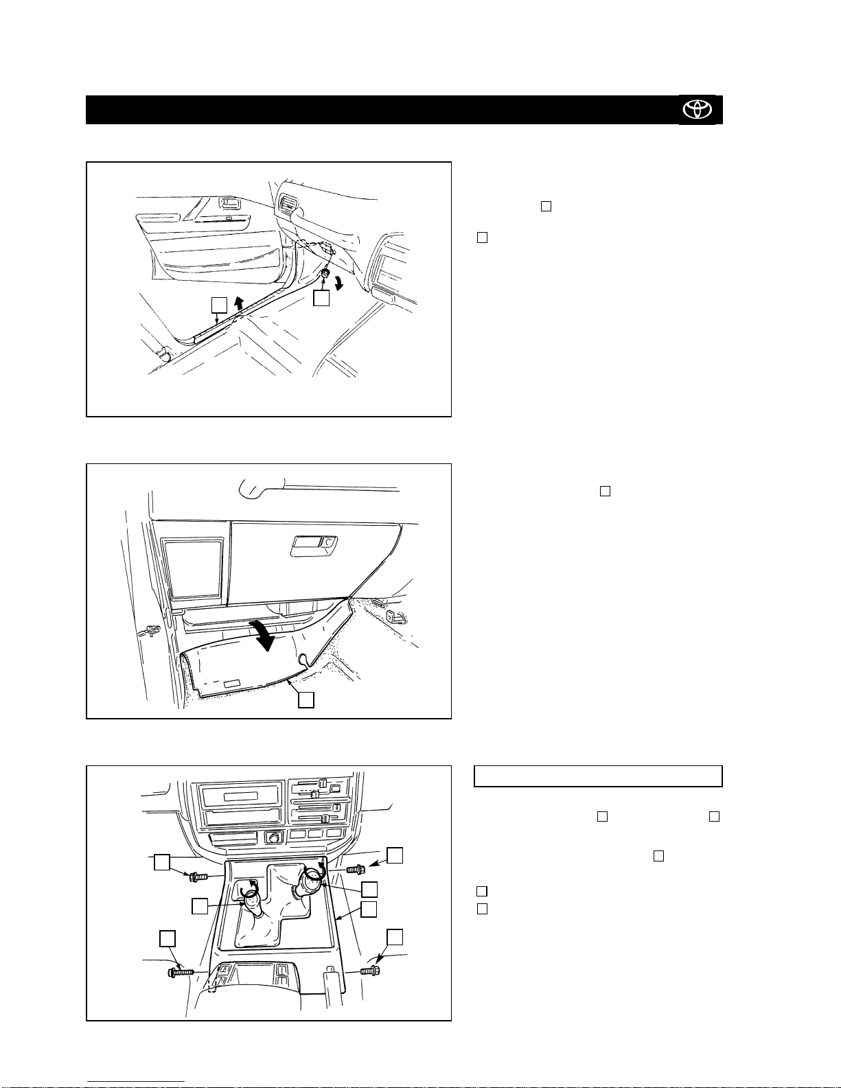
Figure 1
Figure 2
Figure 3
VEHICLE DISASSEMBLY (PASSENGER COMPARTMENT)
Land Cruiser 80 (RHD) - 10
2)
Peel back the carpet .
3
3)
a) Remove the gear and the transfer
shift knobs.
b) Remove the console panel .
: Screws (3x)
: Screw (1x)
8
7
6
5
4
Land Cruiser 80 TOYOTA TVSS IIIB
Vehicle Disassembly (Passenger Compartment)
1)
Remove the passenger’s side front side
step cover .
Plastic nut
2
1
1
2
3
FOR MANUAL TRANSMISSION MODELS
7
7
7
8
4
5
6
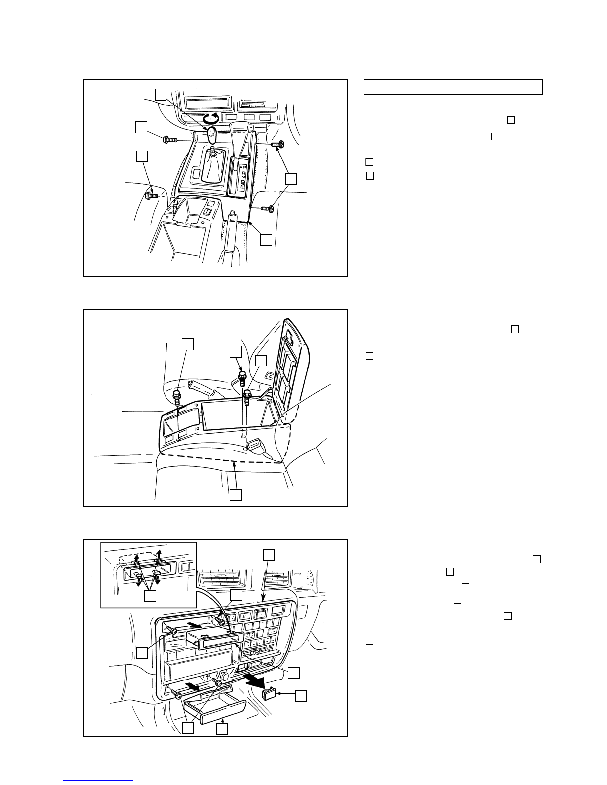
Figure 4
Figure 5
Land Cruiser 80 (RHD) - 11
4)
a) Remove the transfer shift knob .
b) Remove the console panel .
: Screws (3x)
: Screw (1x)
8
7
9
5
5)
Remove the console compartment .
: Bolts (3x)
11
10
6)
a) Remove the accessory compartment
and the ashtray .
b) Remove the screws (4x) securing
the centre cluster .
c) Remove the switch hole cover .
: Locks (4x)
141516
71312
Vehicle Disassembly (Passenger Compartment)
Land Cruiser 80 TOYOTA TVSS IIIB
Figure 6
FOR AUTOMATIC TRANSMISSION MODELS
15
16
7
7
7
7
7
10
9
8
11
11
11
12
13
5
14
 Loading...