

Toyota TVIP V4 Troubleshooting Manual

2009- RAV4 w/Smart TVIP V4 REMOTE ENGINE STARTER (RES)
TROUBLESHOOTING GUIDE
REMOTE ENGINE STARTER
TROUBLESHOOTING GUIDE
Rev. B 01/18/06

TABLE OF CONTENTS
PRE-CHECK 3
RES ECU PIN LAYOUT AND TERMINALS 4-5
ACCESSORY GATEWAY ECU PIN LAYOUT
AND TERMINALS 6
HOW TO PROCEED WITH TROUBLESHOOTING 7
CUSTOMER PROBLEM ANALYSIS CHECK 8
Remote Engine Starter Troubleshooting Guide Page 2
DESCRIPTION PAGE
PROBLEM SYMPTOMS TABLE 9
DIAGNOSTIC OPERATION 10-11
Diagnosis Mode Reset Conditions 12
DIAGNOSTIC CODE BY SCAN TOOL 12
INSPECTIONS
Engine Does Not Start by Remote 13-15
Engine Does Not Stop by Remote 16-17
Engine Stops Unexpectedly 18-19
Failed Registration of Immobilizer ID Code 20-21

PRE-CHECK
REMOTE ENGINE STARTER CHARACTERISTICS
(a) The operation distance varies according to how customers hold the transmitter or where it is used.
(b) Strong external radio waves or other frequency noise may interfere with the Remote Engine
Starter’s operation distance.
REMOTE ENGINE STARTER BASIC FUNCTIONS
(a) Stand on the driver’s side, three feet away from the vehicle.
(b) Turn the transmitter toward the vehicle and press and release the LOCK button twice within two
seconds. Immediately press and hold the LOCK button for three seconds. The hazard lights flash
after three seconds.
Remote Engine Starter Troubleshooting Guide Page 3
(c) The engine then starts, and the hazard lights flash for 20 seconds.
(d) Press the UNLOCK button. The engine stops and hazard lights flash twice.
OR
Press and hold the LOCK button for two or more seconds. The engine stops and the hazard lights
flash once.
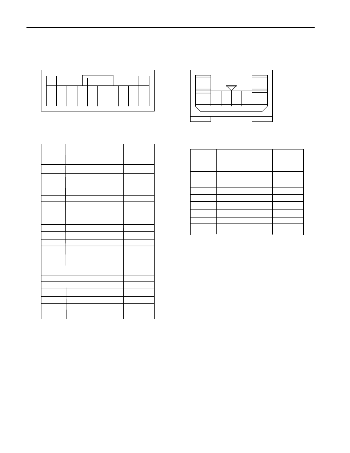
RES ECU PIN LAYOUT
N
N
Remote Engine Starter Troubleshooting Guide Page 4
<Connector>
Part Number: 90980-12258
Color: White
9108 7
20
19 18 17 16 15 14 13 12 11
MALE FRONT VIEW
Terminal
o.
1 MPX Signal
2 ST1 Input *1
3 SHIFT P
4 RES Diag
5 OPTIONINPUT2
6 CHECK ENGINE
LIGHT
7 OPTIONINPUT3
8 (HOOD SW.)
9 STSW Signal *2
10 OBD2 (Diag.) *1
11 +B
12 IG1
13 N.C.
14 ST1 Output *1
15 N.C.
16 GND
17 GND
18 N.C.
19 N.C.
20 OBD2 (Imm. ECU) *1
6 5 4 3 2 1
Content
MPX
ST1I
P
RDIG
OPI2
LDUT
OP13
(DSWH)
STSW
OB2I
+B
IGI
ST10
GND
GND
-
OB20
Signal
Part Number: 90980-11361
Color: White
12
8 7 6 5 4 3
MALE FRONT VIEW
Terminal
o.
1 AM1 *1
2 AM2 *1
3 IGI *1
4 N.C.
5 ACC *1
6 ST2 *1
7 N.C.
8 IG2 *1
Content
Signal
AM1
AM2
IG1
ACC
ST2
IG2
*1: Vehicles without Push Start System only.
*2: Vehicles with Push Start System only.
Remote Engine Starter Troubleshooting Guide Page 5
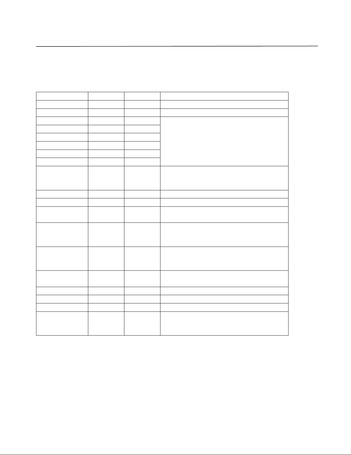
RES ECU TERMINALS
Remote Engine Starter ECU Input/Output Specifications
Signal Symbol I/O Condition
+B +B ECU+B 12V (TYP)
GND E ECU GND 0 V
AM1 *1 AM1 Input
AM2 *1 AM2 Input
IG1 *1 IG1 Output
IG2 *1 IG2 Output
ACC *1 ACC Output
ST2 *1 ST2 Output
IG1
(same terminal
as above)
Hood SW DSWH Input Close : Less than 1V
Shift position P P Input ON : Over (+B-1) V
Check engine
lamp
Diagnosis
communication1
*1
Diagnosis
communication2
*1
BEAN
communication
ST1(IN) *1 ST1I Input ON : Over (+B-1)V
ST1(OUT) *1 ST1O Output Permissible current : 500mA
STSW *2 STSW Output ON : Over (+B-2) V
Remote engine
starter diagnosis
input
IG1 Input ON : Over (+B-1) V
LDUT Input OFF : Less than 2.2V
OB2I Input Pulse generation during communication
OB2O Output Pulse generation during communication
MPX Commu-
nication
RDIG Input ON : Less than 1V
Dropping voltage: Less than 0.2V
ON : Over 6V
Pulse generation
*1: Vehicles without Push Start System only.
*2: Vehicles with Push Start System only.
Remote Engine Starter Troubleshooting Guide Page 6
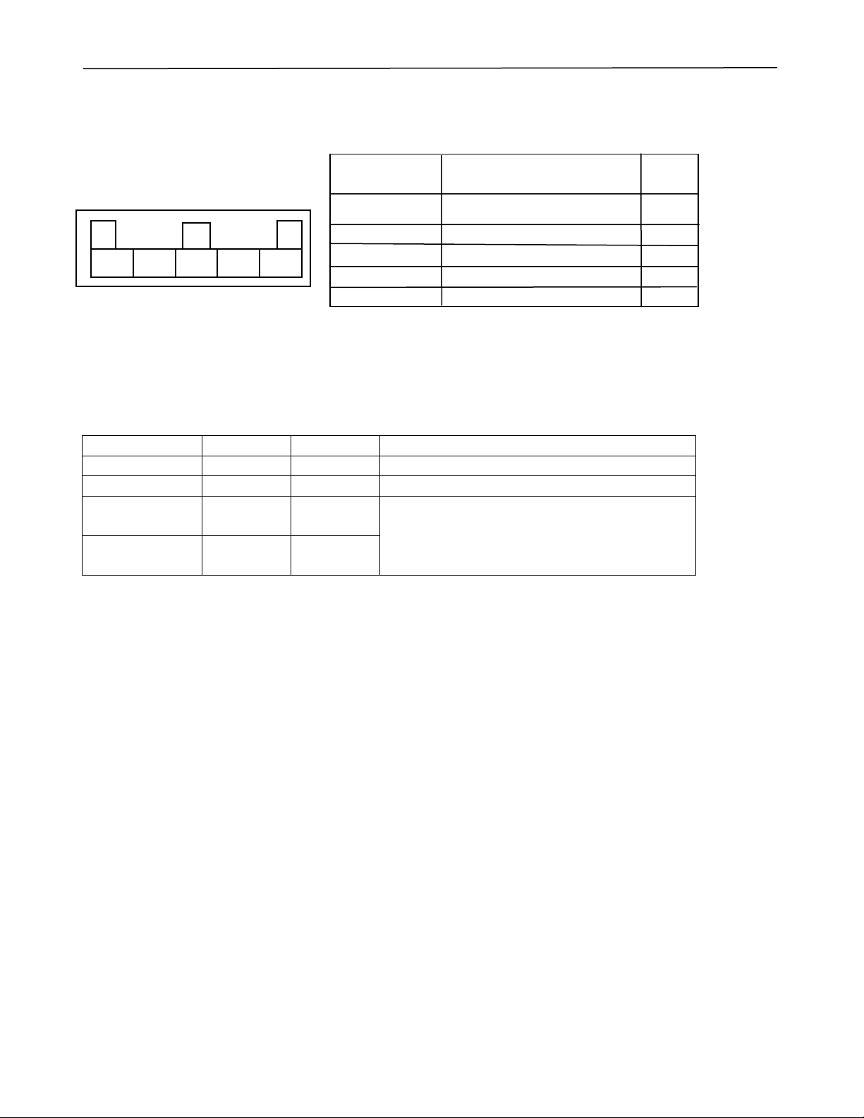
ACCESSORY GATEWAY ECU PIN LAYOUT
<Connector>
Part Number: 90980-10798
Color: Dark gray
5 4 3 2 1
MALE FRONT VIEW
Terminal No. Content Signal
1 MPX Signal for Accessory MPXY
2 N.C. _
3 +B +B
4 GND GND
5 MPX Signal for Vehicle MPX
ACCESSORY GATEWAY ECU TERMINALS
Accessory gateway ECU Input/Output Specifications
Signal Symbol I/O Condition
+B +B ECU+B 12V (TYP)
GND E ECU GND 0 V
MPX signal for
accessory
MPX signal for
Vehicle LAN
MPXY Commu-
nication
MPX Commu-
nication
Pulse generation
Remote Engine Starter Troubleshooting Guide Page 7
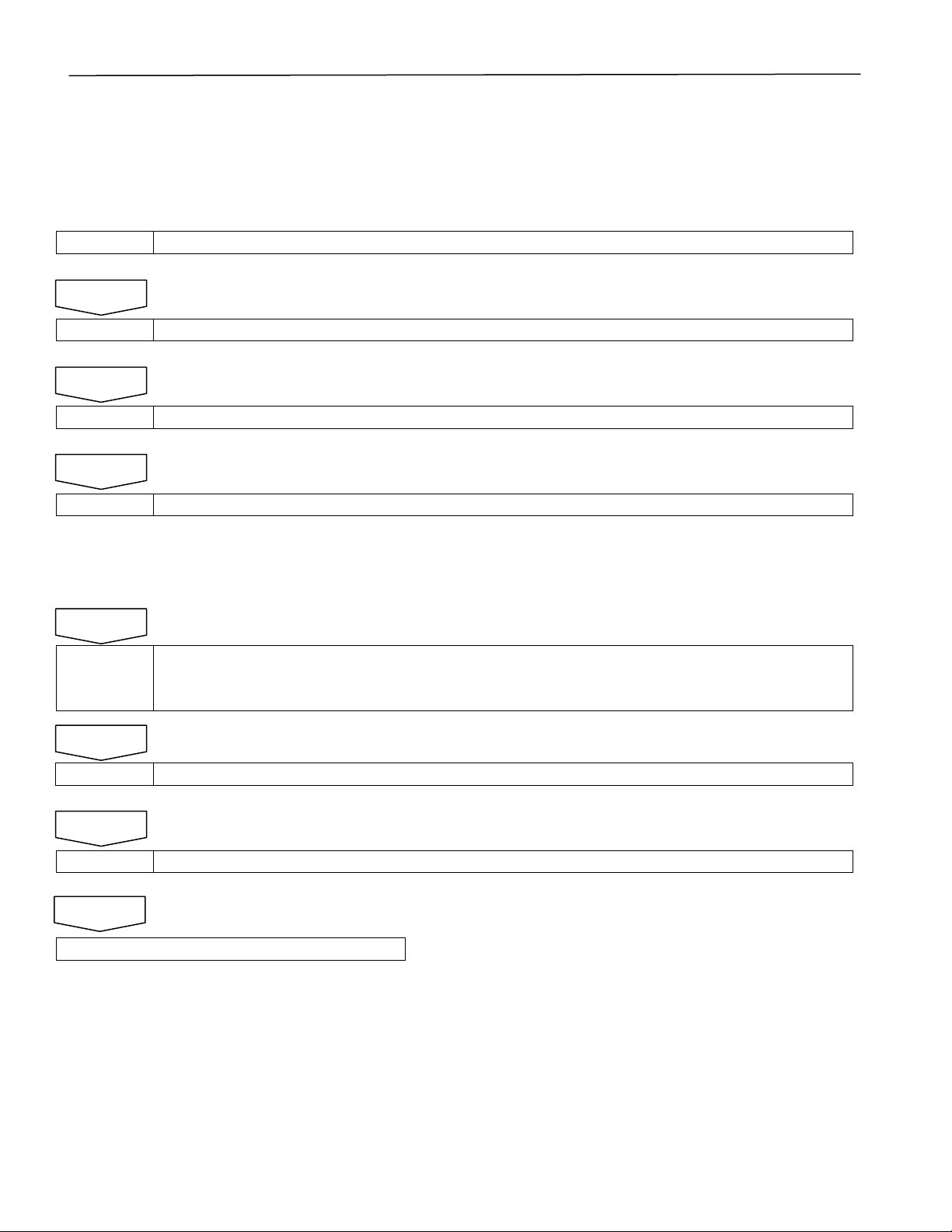
HOW TO PROCEED WITH TROUBLESHOOTING
HINT
z Use these procedures to troubleshoot the Remote Engine Starter.
z The hand-held tester should be used in Step 4.
1 VEHICLE BROUGHT IN FOR SERVICE
NEXT
2 CUSTOMER PROBLEM ANALYSIS CHECK AND SYMPTOM CHECK
NEXT
3 PROBLEM SYMPTOMS TABLE
NEXT
4 OVERALL ANALYSIS AND TROUBLESHOOTING
(a) Diagnostic Mode check, if necessary (see page 10)
(b) Check ECU terminals (see pages 4 to 6)
(c) Check wire harness (see I/I and EWD)
NEXT
5 Please fax the Replacement Authorization Request Sheet and Customer Problem Analysis
Check Sheet to (800) 438-5410 to receive an RES Authorization Number.
For assistance, please call Fujitsu Ten Technical Support at (800) 237-5413.
NEXT
6 CHECK INSTALLATION AND PROGRAMING, REPAIR OR REPLACE
NEXT
7 CONFIRMATION TEST
NEXT
END
 Loading...