

Page 1

TOSHIBA
E6580496 0
ULTRA-COMPACT
DIGITAL INVERTER
VF-SX
OPERATION MANUAL
JUNE, 1993
Page 2

TOSHIBA
TOSHIBA VF-SX INVERTER
OPERATION MANUAL
TABLE OF CONTENTS
INTRODUCTION ............................................................ I-l
CHAPTER 1 Inspection Procedure Upon Receipt
CHAPTER 2 Proper Environment for Installation
CHAPTER 3 External Views and Connection Diagrams
3.1 External Views.................................................3-2
3.2 Connection Diagrams .......................................... 3-4
CHAPTER 4 Application Precautions
CHAPTER 5 Wiring Guidelines and Warnings
5.1 Inverter Wiring................................................5-2
5.2 Installation of a Molded Case Circuit Breaker (HCCB)
5.3 Installation of a Primary Magnetic Contactor (HC)
5.4 Installation of an Output Magnetic Contactor (MC)
5.5 Installation of an External Overload Relay
5.6 Installation of an Input Reactor...............................5-6
5.7 Incorrect Wiring and Incorrect External Components
5.8 Basic Wiring Recommendations ................................. 5-7
Chapter 6 Standard Connections ........................................ 6-1
6.1 Examples of Standard Wiring .................................. 6-2
6.2 Terminal Functions ........................................... 6-7
Chapter 7 Parameter Groups
7.1 Definitions of SX Drive Group Parameters
7.2 Parameter Group Tables
Chapter 8 Basic Operation Theory
8.1 Operation of the Touchpad Control Panel
8.2 Display Modes.................................................. 8-4
8.2.1 Drive Mode................................................... 8-5
8.2.2 Monitor Mode
8.2.3 Programming Mode............................................8-10
8.2.4 Jogging Mode from the Touchpad..............................8-11
8.3 PANEL/REHOTE Control ........................................ 8-12
8.4 Selection of Stopping Method from the Touchpad
8.5 Starting the Drive from the Touchpad
8.6 Changing Frequency from the Touchpad
8.7 Error Reset................................................... 8-17
8.8 Warning Displays
8.9 Fault Relay Information ..................................... 8-19
.................................................
.......................................
..............................................
.......................................
........................................
............................................
...........................
.........................
......................
..............................
........
............
............
..................
..........
....................
.....................
..........................
..........................
...............
I-I
2-1
3-1
4-1
5-1
5-4
5-5
5-5
5-6
5-6
7-1
7-2
7-3
8-1
8-2
8-8
8-12
8-14
8-16
8-18
Page 3

^_____________________TOSHIBA
CHAPTER 9 Fundamental Operation Parameters and Functions [GC~ .F] . 9-1
9.1 Setting of Voltage and Frequency Characteristics
9.1.1 Maximum Frequency [fH]
9.1.2 Base Frequency [UL]
9.1.3 Torque Boost [Ub]
9.1.4 V/f Patterns [P t].........................................9-8
9.2 Upper Limit Frequency and Lower Limit Frequency [U L ,L L] 9-9
9.3 Forward and Reverse Run [f,rj
9.3.1 Operation from the Touchpad ............................... 9-10
9.3.2 Operation Using External Signals
9.4 Acceleration and Deceleration
9.4.1 Acceleration and Deceleration Time [R C C I },
.........................................
...........................................
______________________
.....................................
...................... .........
.........................
...............................
............
9-4
9-4
9-5
9-7
9-10
9-11
9-14
[dèe / ], [R C C d], [d E C c]..............9-14
9.4.2 Acceleration/Deceleration Pattern [Pt / ], [Pt P] . . 9-15
9.4.3 Selection of Acceleration/Deceleration 1 and 2
[Rd^], [Rd^F]
9.5 Setting of Standard Parameter Groups [ t ^ P]
.......................................
............
9-17
9-19
Chapter 10 Terminal Selection Parameters [GC.S t]
10.1 Command Mode Selection [ cnodi
10.2 Frequency Setting Commands [P fl R d]
10.3 Parameter Setting Disable Function [PR 0 d]
10.3.1 Security Considerations and Parameter [PR Od] .... 10-4
10.4 Input Terminal Selection [ I t b]
10.5 Output Terminal Selection [Otb]
10.6 Low Speed Signal Output and Speed Reached Signal Output
.........................
.......................
...............
...................
.............
......................
[LF], [LFHL], [FrCH], [CCH], irrCH] , 10-7
10.6.1 Low Speed Signal Output Frequency [ i. F] and Speed
Reached Logic Signal [ LFHL]
10.6.2 Speed Reached Signal Output irCH]
10.7 Frequency Setting via Remote Control Signals
10.7.1 Types of Frequency Setting Signals
10.7.2 RR Terminal Input Priority C C ], [ I U I O] . . 10-12
10.8 Frequency Setting Signals [P / ], [F*“P I ] and
[PP], [P —PP]
10.9 Jogging Run via Remote Control [ tJ 0 0], [d SEP] 10-14
10.10 Multiple Speed Run [ST.D], [StI — StI] . . 10-17
......................... ....................
................... .........
.................
..............
.....................
10-1
10-2
10-3
10-3
10-4
10-6
10-7
. . . 10-7
10-9
10-10
10-12
Page 4

______________________TOSHIBA
_____________________
3
Chapter 11 Protection Parameters [ Gr.Pn
11.1 Regenerative Discharge Braking Selection [P b] and
Overvoltage Limiting Action Selection [OP 5 b]
11.2 DC Injection Braking Start-up Frequency [dbF],
DC Injection Braking Voltage [ dbU] t and DC Injection
Braking Time [d b b]..................... .............11-4
11.3 Emergency Stop [EScP]
11.3.1 Emergency Stop from the Touchpad...........................11-6
11.3.2 Emergency Stop Using Remote Control Signals
11.3.3 Emergency DC Injection Braking Stop Control Time
[fdbfc] ................................................11-8
11.4 Retry [T try]
11.5 Power Control Function [UuC]........................... 11-10
11.6 Electronic Thermal Protective Level [b Hf~] 11-11
11.7 Stall Prevention Function Activation Level [5 fc /.] ... 11-11
11.8 Electronic Thermal Protection Characteristic Selection
[0 L il]
11.9 Retention of Trip [t^CL]
Chapter 12 Control and Communication Parameters [ 0 f. C C ] 12-1
12.1 Differences Between Startup Frequency and Operation Starting
Frequency....................................................12-2
12.2.1 Start-Up Frequency [F~5t]
12.2.2 Operation Starting Frequency [ Frurt]
12.2.3 Operation Starting Frequency Hysteresis [ FHdS] . . . 12-4
12.3 Jump Frequency and Jump Bandwidths [ F J.H],
[ F J / ] and [ b F <J / ], [ F J d ] and [ b F J (? ].
[ F J 3 ] and [ b F J 3 ] 12-5
12.4 PWM Carrier Frequency [CF] and
Motor Tone Selection [CF5]
12.5 Output Voltage Adjustment rPOUb] and Power Voltage
Compensation Function [ ppddi .......................... 12-6
12.6 Automatic Torque Boost [ Rub]
12.7 Slip Frequency Compensation [5FC]
.............................................
.....................................
.............................................
....................
................................
.............................
......................
.................................
.........................
.................
.... 11-1
.............
.............
11-2
11-6
11-7
11-8
11-11
11-11
12-3
12-4
12-6
12-8
12-10
Page 5

TOSHIBA
Chapter 13 Meter Adjustment Parameters [ Gr.RH] ............. . . . . 13-1
13.1 Meter Connections [FnRfl] . ......................... 13-2
13.1.1 Connection of a Frequency Meter [F fl]
13.1.2 Connection of an Ammeter [R /7]
13.2 Frequency Setting Signal [rr—b], [rr—C]
13.3 Universal Unit Multiplication Factor [d 5 P (?]
Chapter 14 General Drive Specifications
14.1 Drive Specifications ....................................... 14-2
14.2 External Dimensions ........................................ 14-4
Chapter 15 Options.......................................................15-1
15.1 Input Reactor
15.2 Radio Noise Reduction Filter
15.3 Braking Resistor ........................................... 15-2
15.4 Connection Cable ........................................... 15-2
Chapter 16 Error Displays, Explanations, and Remedies
16.1 Inverter Trip Causes and Remedies
16.2 Other Errors and Remedies
Chapter 17 Maintenance and Inspection ................................... 17-1
Chanter 18 Storage and Warranty ....................................... 18-1
18.1 Storage..................................................’ ] 18_2
18.2 Warranty...................................................] 18-2
Appendix....................................................... H-1
APPENDIX 1 — TABLE OF TRIP CODES AND WARNING CODES
APPENDIX 2 ~ INPUT TERMINAL INFORMATION AND OUTPUT TERMINAL
INFORMATION
APPENDIX 3 — LEO ALPHANUMERIC CROSS REFERENCE
..............................................
...................................
.................................................
..........................
..........................
..............................
.........................
..............
................
............
..................
............
.....................
! ! A-2
13-2
13-3
13-5
13-7
14-1
15-2
15-2
15-1
16-2
16-4
A-3
A-4
Page 6

TOSHIBA
i-i
IHTRODUCTIOH
Thank you for purchasing the Toshiba Compact Inverter "TOSVERT VF-SX".
The VF-SX variable speed drive Is a high performance Inverter that has numerous
built-in functions, making It suitable for many applications. This Inverter Is
very easy to program and operate. All instructions are entered via the membrane
keyboard panel (the "touchpad"). The latest technology and features, including
current limit, auto-restart, dynamic braking, and stall prevention are Included.
This product offers flexible operation for numerous applications, and helps
prevent nuisance tripping, even for difficult loads and applications.
Please thoroughly review this manual before attempting use of the VF-SX drive,
so that the features of this drive can be properly applied for each unique
applIcatlon.
Please keep this manual for future reference, operation, and maintenance of the
VF-SX drive.
Always ground the Inverter in accordance with Article 250 of the National
Electrical Code or Section 10 of the Canadian Electrical Code, Part I. The
grounding conductor should be sized In accordance with NEC Table 250-95 or CEC,
Part I, Table 16.
See Chapter 6 for simplified power and control wiring instructions and
recommendations.
Page 7

Page 8

TOSHIBA
CHAPTER 1 Inspection Procedure Upon Receipt
1-1
Page 9

1-2
1. Inspect the Toshiba Model VF-SX variable speed drive. Confirm that no
parts have been damaged during transit.
2. Confirm that the model number inscribed on the nameplate is the same as
that ordered.
3. If the inverter will not be placed in service immediately upon receipt,
store the device in a dust free environment. Be sure the room is
ventilated with cool, dry air. Store this device in its original packing
material whenever possible.
4. Every reasonable precaution is taken during the production, packaging, and
shipping of this device to prevent damage to the unit before installation.
If there is any damage upon receipt, contact the dealer and the freight
company immediately.
TOSHIBA
Page 10

TOSHIBA
CHAPTER 2 Proper Environment for Installation
2-1
Page 11

2-2
The VF-SX inverter Is a solid state device. Use caution to install the device
in the proper environment, as instructed in the general recommendations shown
below. See Chapter 14 for detailed specifications of the proper operating
environment.
1. Confirm that the input power supply is within +/- 10% of the nominal
voltage. The protective circuit will activate and trip if the permissible
input voltage range is exceeded. Extreme voltage conditions may damage
the inverter.
2. Do not install the inverter in places where high temperature or humidity
are present. Do not install in dusty environments, or environments
contaminated with metal particles or metallic powder.
3. Do not mount the inverter on any device subject to intense vibration.
4. Operate the inverter only in an environment between -10 deg C to 40 deg C.
The inverter generates heat when operating. When it is installed on a
subpanel or backplate be sure there is adequate ventilation on all sides
of the inverter, including the back of the inverter where the heat sinks
are located. In high ambient temperatures it may be necessary to remove
the stick-on seal on the top of the inverter to allow more ventilation
through the Inverter.
Certain electrical equipment, if installed too near the inverter, may
5.
cause malfunctions. Examples of this type of equipment can include:
If a magnetic contactor is installed near the inverter install a
A.
urge suppression device across the coil of the contactor to prevent
surging magnetic fields from interfering with the operation of the
inverter.
Do not install the inverter near fluorescent lighting.
B.
Keep other heat generating electrical equipment, such as resistors
C.
or heaters, away from the inverter.
Always properly ground the inverter chassis to prevent electrical noise
6.
and nuisance tripping. Proper earth ground should not exceed 100 ohms.
Install the inverter ONLY on incombustible subpanels, such as a metal
7.
subpanel. If the inverter is installed on a heat insulating subpanel then
mount the inverter on a metal subpanel first, and attach this assembly to
the insulated subpanel.
Always have at least 10 centimeters free space above and below the
8.
inverter. Always have at least 5 centimeters free space on EACH side of
the inverter. If more than one inverter is mounted in a row, leave at
least 10 centimeters between each drive, from side to side. If fans are
installed in the enclosure or near the drives this space requirement may
be reduced. Consult the Toshiba factory for details.
TOSHIBA
Page 12

TOSHIBA
CHAPTER 3 External Views and Connection Diagrams
3-1
Page 13
3-2
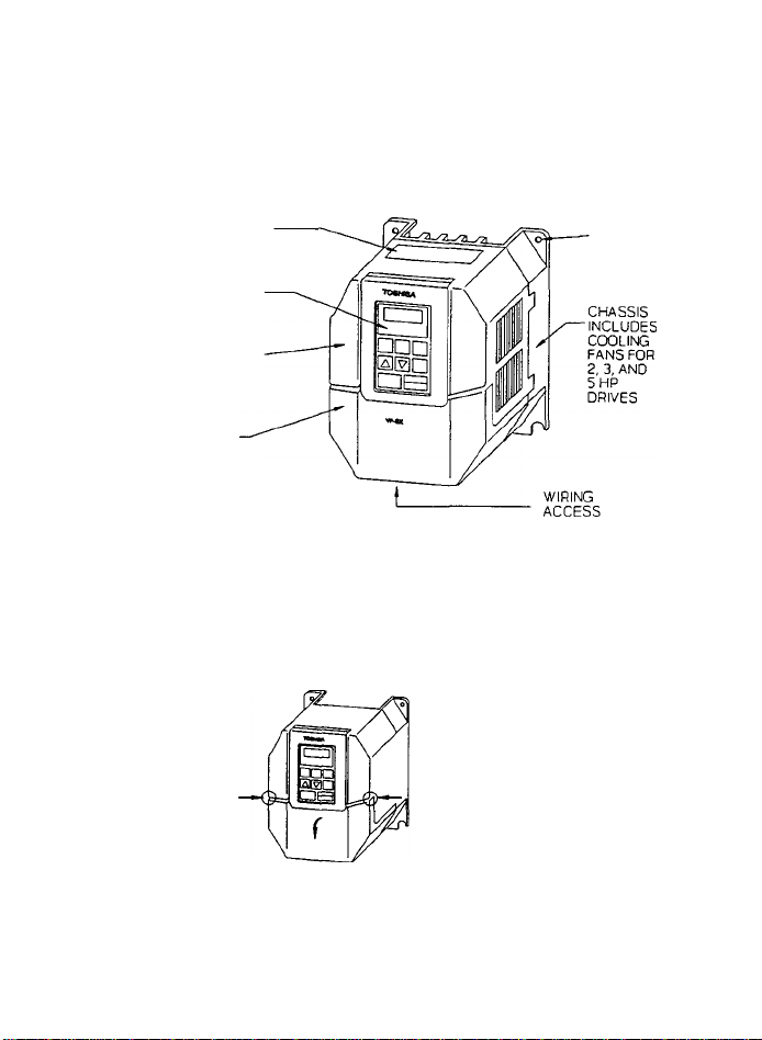
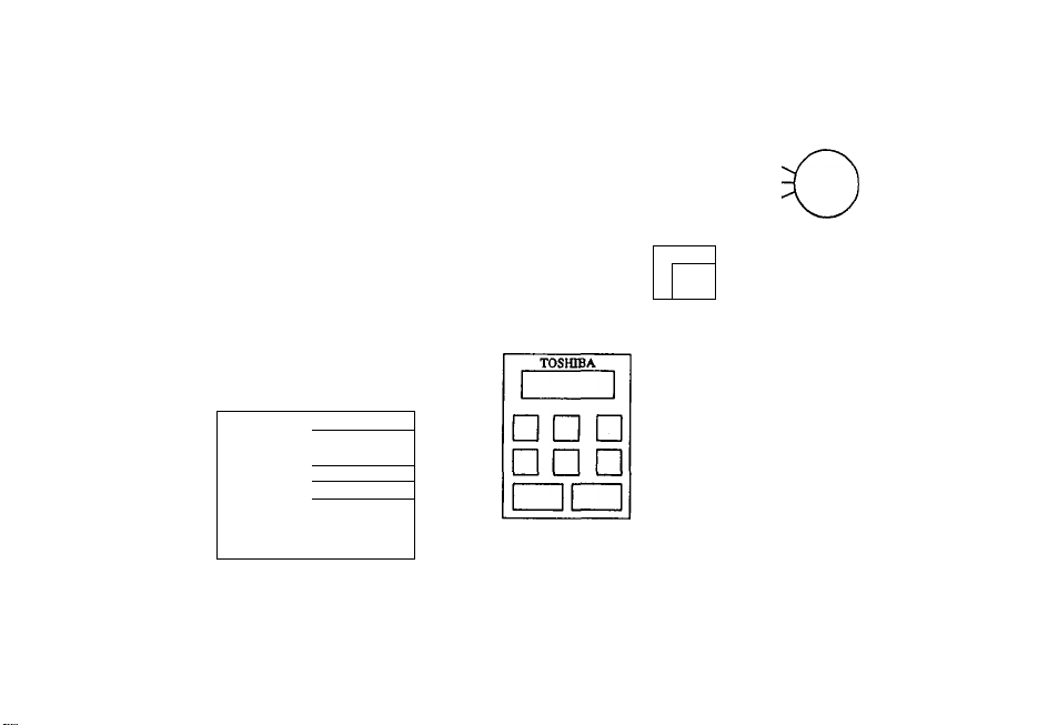
3.1 External Views
TOSHIBA
REMOVE THIS SEAL
WHEN USING THE
INVERTER IN A HOT
PLACE
TOUCHPAD CAN
BE REMOVED
UPPER COVER
DOES NOT NEED
TO BE REMOVED
UNLESS THE
EXTERNAL SIGNAL
SELECTION
JUMPERS ARE
CHANGED
LOWER COVER MUST
BE REMOVED WHEN
THE TOUCHPAD IS
REMOVED OR WHEN
WIRING IS
CONNECTED TO THE
TERMINALS
PRESS THE LOWER COVER
ON BOTH SIDES (AS
SHOWN) SWULTANEOUSLY.
PULL THE COVER FORWARD,
TO INSTALL THE COVER,
insert the COVER CLASPS
IN THE BOTTOM HOLES,
ROTATE THE TOP OF THE
LOWER COVER BACK INTO
POSTITON, AND GENTLY
PRESS UPPER CLASPS INTO
PLACE
FOUR
INSTALLATION
HOLES
Page 14

CONTROL CIRCUIT
TERMINAL BLOCKS
MAIN CIRCUIT
TERMINAL BLOCKS
THESE terminal
BLOCKS ARE FOR
INPUT, OUTPUT,
GROUND, AND
OPTIONAL BRAKING
RESISTOR
CONNECTIONS
TOSHIBA
LOWER COVER INLET
CONNECTOR FOR
TOUCHPAD OR
TOUCHPAD EXTENSION
CABLE
SCREW HOLD FOR
TOUCHPAD
TO REMOVE UPPER
COVER, INSERT A
BLADE SCREWDRIVER
UNDER 4 CLASPS
AND LIFT GENTLY
CHARGE I AMP
DO NOT CHANGE WIRING
OR REMOVE UPPER
COVER WHEN LIT
3-3
Page 15
SINGLE PHASE
MCCB
POWER » ►
SUPPLY ^
SmOLE PHASE * ^
2Ù0.230VAC, 50/60HZ
RESET
FORWARD
REVERSE'
: : ¿‘ÎNTÊWloâC
MULTI- / : 1 f ■■■■
FUNCTION T T .............
SIGNAL \ ! ■...............
INPUT ^ ‘
AUTO +
REFERENCE
.......
....
■
........
..........................
ANALOG INPUT
. \AUtO :
^
] i
♦DBR NOT AVAILABLE ON SINGLE PHASE 1/8, 1/4HP UNITS.
VF-SX
RST
F
R
ST
cc
SSl
JOG/SS2
BX/SS3
AD2
PP
RR
CC
PA PB
GND(E)
D
FAULT
T1(U),
T2(V),
T3(W)
FLA
FLB
' FLC
FM/AM.
CC
P24
LOW/LL
RCIVUL,
M
FAULT SIGNAL
OUTPUT
FREQUENY/CURRENT
r*‘™X"*:i.SipNAL
I \SCAl£r
• ; 1mA
+24VÒC
T MULTI- FUNCTION
i SIGNAL OUTPUT
MAX
TOTAL
la
w
N»
O
O
CD
n
D»
"t
A>
B
(/)
CO
Page 16

THREE PHASE
MCCB
POWER
--------------
SUPPLY
--------------
THRBBPHÂSB ’ *
200 - 230VAC, 5(V60Hz
RESET
* FORWi^
i « RÌBvSiSÈ''
! isINTERLOCK
....
MULTI- / ; ± -
FUNCTION f ;
SIGNAL \ '
INPUT ^
................
ANALOG INPUT
iAUTO
¡REFERENCE
+ .¡.j..
..........
..............
;vAUTO
ÌìjìanrTv;;],
-.JÎÏ7
*DBR NOT AVAILABLE ON THREE PHASE 1/8, I/4HP UNITS.
L1(R)
U(S)
L3CD
RST
F
R
ST
cc
SSI
JOG/SS2
EX/SS3
AD2
PP
- RR
; CC
}■ IV
DBR*
PA PB xi(U)
VF-SX
FAULT
RELAY.
□ □ □
□ □ □
GND{E)
7T
■fi
FM/AM -
LOW/LL
RCHAJL
T2(V)
T3(W)
FLA
FLB
FAULT SIGNAL
OUTPUT
FLC
FREQUENY/CURRENT
-■‘•FtnX—
: ¡SCALE/'
I ;AT
: MmA
cc
i +24Vdc
P24
..f-...
MULTI- FUNCTION
M
MAX
TOTAL
SIGNAL OUTPUT
O
C/3
s
5
>
Page 17

Page 18

TOSHIBA
CHAPTER 4 Application Precautions
4-1
Page 19

4-2
1. If the drive is very lightly loaded (approximately 5*) or if the inertia
of the driven load is very small, the drive may become unstable. The
result could be abnormal vibration or overcurrent trip. If this condition
persists lower the PWM carrier frequency (parameter [C F]). See Chapter
12 for instructions.
2. Unstable results may occur if:
A. The output rating of the drive is less than the output rating of the
motor.
B. The drive is used with a motor with special ratings, such as an
explosion proof motor, or a motor specially built for high inertia
applications.
C. The drive is used with a pulsing load, such as a load requiring
repeated piston type operation.
3. The motor will coast to stop if the power is lost. If an immediate stop
or very quick deceleration of the motor is required use an auxiliary brake
device. Select the appropriate stopping method as described in Chapter 11
for an emergency stop.
4. GROUNDING
The inverter should be grounded in accordance with Article 250 of the
National Electrical Code or Section 10 of the Canadian Electrical Code,
Part I. The grounding conductor should be sized in accordance with NEC
Table 250-95 or CEC, Part I, Table 16.
TOSHIBA
Page 20

TOSHIBA
CHAPTER 5 Wiring Guidelines and Precautions
5-1
Page 21

5-2
This chapter of the manual discusses some of the basic wiring configurations and
external devices commonly associated with the installation and application of
variable speed drives. Local codes, specifications, requirements, and operating
conditions may require the addition of other devices or modifications to the
following basic recommendations.
TOSHIBA
5.1 Inverter Wiring
(Refer to Figure 5.1 and 5.2)
1. It can be difficult to remove the upper cover after wiring, so change the
jumper selectors J1 or J2 on the internal PC board for "external signal
selection" before wiring the inverter. See Chapter 6 for the approximate
location of jumpers J1 and J2 inside the drive.
When a signal between 0 to 5V is used as frequency signal, switching the
jumper is necessary. Refer to Chapter 10, Table 10-9 for details.
2. Always turn the main line power OFF and confirm that there is no voltage
present with a testing tool before connecting power, motor leads, or
control wires.
3. WTOJIN^ Wait until the "CHARGE" lamp has turned off before working on
the drive. An internal capacitor stores electrical charge in the inverter
and electrocution may result due to inadvertent contact with this
capacitor. Do not touch the terminals or remove the cover while the
"CHARGE" lamp is on. This indicator is located in the lower right-hand
side of the drive near the terminal blocks, and it is a brightly lit red
LED when the drive is fully charged.
4. WARNING: Do not wire input power to the output terminals (U, V, W) of the
drive, this will damage the drive. Before energizing, confirm that motor
leads are attached to terminals U, V, and W and that the main power leads
are attached to terminals R, S, and T.
5. Exercise caution when wiring the control signals, as shown.
A. Install a surge suppressor on any electromagnetic coil on any
contactor wired to the drive. This includes line and load side
contactors.
B. Use shielded wire or twisted pair wire for control circuit wiring.
Keep this wire isolated from power wire.
C. Always isolate the input control signals from the main power wiring.
This restriction applies to all control terminals except FLA, FLB,
and FLC.
6. Wire sizes:
A. For wire to an ammeter, wire to a frequency meter, and wire carrying
input speed reference signals, use at least 16 gauge shielded wire.
B. For all other control wiring, use at least 12 gauge PVC coated wire.
Page 22

TOSHIBA
Inverter Main Circuit Terminal Block
Figure 5.1 Main Circuit Wiring
, 5-3
Page 23

5-4
TOSHIBA
MCCB
MC
R
U
V
s
W
T
F
Forward
Run/Stop
—oln
---
L_o o
----
/^jr^MCCB-Trip Coil
—
FLB
FLC
R
h
CC
Reverse
FLA
Figure 5.2 Simplified Power and Control Wiring
Run/Stop
5.2 Installation of a Molded Case Circuit Breaker (MCCB)
1. Install a molded case circuit breaker (HCCB) on the line side of the drive
for protection of the incoming power wiring only.
2. Turn the drive ON and OFF via control devices or the touchpad whenever
possible, and not by manual operation of the HCCB or MC. Use the control
terminals F. R, and CC to receive control signals from the appropriate remote
control devices.
Page 24

TOSHIBA
5-5
5.3 Installation of a Primary Magnetic Contactor (MC)
1. Install a magnetic contactor (HC) on the line side of the inverter to prevent
restart after either a loss of power, a trip of an external overload relay, or
an operation of the internal drive protective device.
2. The VF-SX has an internal fault detection relay. The HC can be opened when
the inverter protective circuit operates by connecting this contact point to the
primary MC operation circuit.
3. The inverter can be used without an HC. In this case use a shunt trip style
main breaker (MCCB) and open the main circuit by tripping the breaker when the
inverter protective circuitry operates.
4. When using a braking resistor with an overload relay, install an HC or an
MCCB with shunt trip on the line side of the inverter. Connect these devices so
that the power circuit will open when the internal fault detection relay (Ft) or
externally installed overload relay operates. Emergency stop is also possible
by connecting the overload relay contact point between the terminals of SS3 (EX)
and CC of the inverter. See Chapter 11 for details of the Emergency Stop
parameter.
5. Use control signals on terminals F, R, and CC for frequent starting and
stopping. Avoid turning the inverter on and off with the primary HC.
6. Always install a surge suppressor across any contactor coil.
5.4 Installation of an Output Magnetic Contactor (MC)
1. Avoid starting and stopping the motor with an output contactor (HC) installed
between the inverter and the motor. Excessive surge currents could damage the
output devices of the drive. Use control signals on terminals F, R, and CC
instead.
2. For Bypass Operation; Be sure the motor has stopped and the drive is OFF
before turning on the bypass contactor to run the motor directly from line power.
Use an external timer, PLC, or similar device as required. Always make sure that
the bypass contactor does not allow voltage to backfeed into the inverter output
terminals.
Page 25

5-6
TOSHIBA
5.5 Installation of an External Overload Relay
1. An electronic overload relay is standard on the VF-SX drive. However, for
the following applications Toshiba recomtnends Installing an overload relay that
coordinates with the internal solid state relay and the motor connected to the
drive. Connect the external relay between the drive and the motor.
A. When using a motor with non-standard current ratings, or the motor
ratings are not comparable to standard duty motors.
B. When operating a single motor smaller than the rating of the drive.
C. When operating several motors simultaneously from the drive. In this
case Install an overload relay on EACH motor.
2. When applying the VF-SX drive to a constant torque load, change the
electronic overload characteristics, or Install a separate overload relay. See
Chapter 11, Parameter [ bHrj.
3. When a motor continuously runs at low speeds it is recommended to use a motor
with an Internal overload relay, for additional protection.
5.6 Installation of an input Reactor
An input reactor Is used to suppress high frequency elements and sudden changes
In power fluctuations. Install an Input reactor when the Inverter Is connected
to electrical systems with the any of the following characteristics:
1. When the power capacity Is 200 KVA or more and the power capacity is
10 times or more than the Inverter capacity.
2. When the Inverter Is connected to the same system as a thyristor
commutation type controller.
3. When the inverter Is wired to an electrical system which also
contains a distortion source such as an arc furnace or a large
capacity inverter.
5.7 Incorrect Wiring and Incorrect External Components
WARHINS:
DO NOT INSTALL A POWER FACTOR IHPROVEHENT CAPACITOR ON THE INVERTER INPUT OR
OUTPUT. Current and voltage surges associated with the use of power factor
capacitors can damage the drive components.
If power factor correction is required add an optional input line reactor to
correct power factor.
Page 26
TOSHIBA
Radio Freouencv Interference
During operation of the drive there may be noise generated by the drive in the
frequency range associated with radio transmission signals. This noise may
adversely affect sensitive electronic equipment near the drive. If this
condition persists install a RF/EMI (Radio Frequency or Electromagnetic
Interference) filter on the input to the drive. Shield the motor leads in
metallic conduit. These steps will reduce radio frequency interference.
Contact Toshiba for details, or see Chapter 15.
WARWIH6:
Do not operate or energize the inverter before checking between the motor and the
inverter for mis-wiring or short circuits in the motor. Do not operate the drive
if the motor is shorted. Do not ground the neutral point of the motor star
winding.
5-7
5.8 Basic Wiring Recommendations
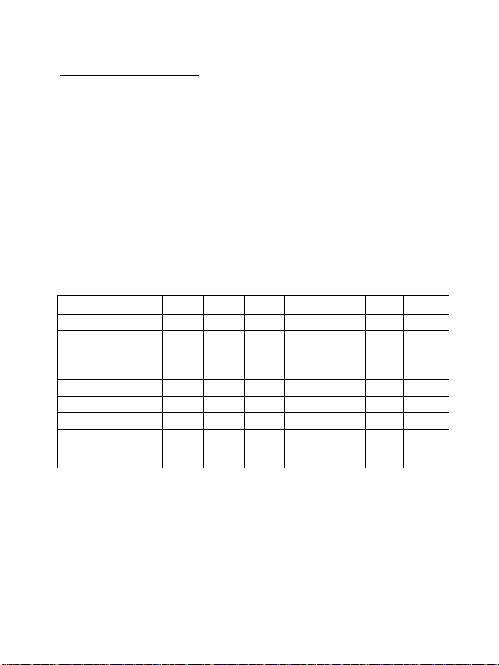
TABLE 5-1: BASIC WIRING RECOHMENOATIONS
2007UP
DRIVE MODEL VFSX- 2001UP
KW RATING 0.1 0.2
HP RATING
1/8 1/4
MCCB SIZE 5 A
HC AMPS (1) 12 A
OL RELAY RATING 0.7 A
POWER WIRE SIZE 12 GA
CONTROL WIRE SIZE 18 GA
WIRE SIZE FOR
REGENERATIVE
BRAKING RESISTOR
N/A N/A 14 GA
2002UP 2004UP
0.4 0.75
1/2
5 A 5 A 10 A
12 A 12 A
1.3 A 2.3 A
12 GA
12 GA
18 GA
18 GA 18 GA
2015UP1
1.5
1 2
15 A 20 A
12 A 12 A
4.2 A
6.6 A
12 GA 12 GA
18 GA
14 GA
12 GA 12 GA 12 GA 1
2022UP12037UP1 1
2.2 3.7 1
3 5 j
30 A 1
12 A
18 A 1
9.3 A 15 A 1
12 GA 10 GA 1
18 GA 18 GA 1
NOTES:
1.
Always use a surge suppression device on the coil of the MC contactor.
Use shielded cable on control circuits. See Figure 5.2.
2.
3.
Use 10 gauge wire or larger for ground circuit.
4.
Power wire sizes in table above are minimum size. For cable lengths over
100 feet, or where voltage drops may cause application problems, larger
wire may be required.
Page 27

Page 28

TOSHIBA
Chapter 6 Standard Connections
6-1
Page 29
6-2
The items printed in Italics in this chapter are Paraaeter names.
Refer to Chapter 7 for a list of all parameter names and Chapters 8 through 13
for instructions to set or adjust the parameters.
TOSHIBA
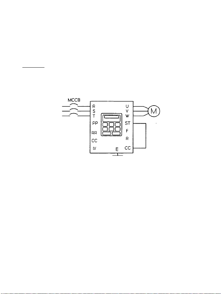
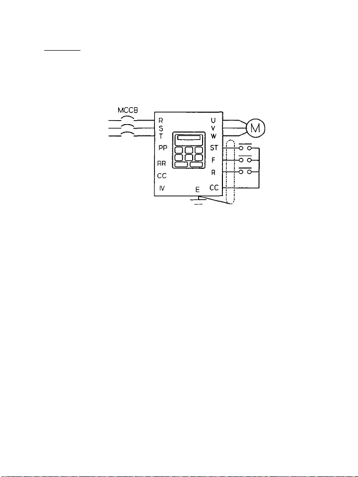
6.1 Examples of Standard Wiring
Example 1: To set the operation frequencies, and conduct forward/reverse run
and/or decelerating stop from the touchpad.
5X DRIVE
Figure 6.1
Setting: In the parameter group [Ci~. 5 t ] the Coaaand Mode Selection is set
to 3 (control terminal or touchpad input). Also, in the same parameter group,
the Frequency Setting Mode Selection is set to 3 (control terminal or touchpad
input). All Model VF-SX drives are shipped with these settings as the factory
default settings.
In Figure 6.1 above:
1. Incoming power is 200-230 volts, three phase, 50 or 60 Hz.
2. A factory installed jumper is present between terminals ST and CC.
3. All drive operation is from the touchpad control panel.
Page 30
TOSHIBA
Example 2: To set the operation frequencies from the touchpad, and conduct
forward/reverse run, decelerating stop, and/or coast!ng-to-stop with external
signals.
6-3
5X DRIVE
Figure 6.2
Setting; In the parameter group [0 l~. 5 t ] the Command Mode Selection is set
to 3 (control terminal or touchpad input). Also, in the same parameter group
the Frequency Setting Mode Selection is set to 2 (only touchpad input valid).
In Figure 6.2 above:
1.
Incoming power is 200-230 volts, three phase, 50 or 60 Hz.
2.
When the ST-CC contact is open the drive will "Coast-to-Stop".
3.
When the ST-CC contact is closed, and the F-CC contact is closed the
drive will run "Forward". If the F-CC contact is opened the drive
will decelerate stop.
4.
When the ST-CC contact is closed, and the R-CC contact is closed the
drive will run "Reverse". If the R-CC contact is opened the drive
will decelerate stop.
Page 31

6-4
Example 3: To set the operating frequencies with external signals and conduct
the forward/reverse run and decelerating stop from the touchpad.
TOSHIBA
5X DRIVE
Figure 6.3
Setting: In the parameter group [C S fc ] the Comand Mode Selection is set
to 2 (only touchpad input valid). In the same parameter group the Frequency
Setting node Selection is set to 1 (only terminal input valid). When the
external signals are input at Terminal IV (see case 3 above), set Teminal IV
Input, also in parameter group [0i~. 5 fc], to 1 (engaged). In this case, the
current input on the IV terminal (4-20mA) will be the standard default setting.
When a 0-5V signal is the required control signal, set the jumper JP2 on the PCB
to V. When a O-IOV signal is to be chosen the input will be from terminals RR
and CC. When using 0-5V set the jumper JPl on the PCB to 5V.
In Figure 6.3 above:
1. Incoming power is 200-230 volts, three phase, 50 or 60 Hz.
2. Speed reference signal #1 is a potentiometer.
3. Speed reference signal #2 is a O-IOV DC control input signal.
4. Speed reference signal #3 is a 0-20mA, 4-20raA, or 0-5V DC control
input signal.
5. Jumpers JPl and JP2 are shown in their approximate location on the
internal printed circuit board, behind the front cover.
Page 32

TOSHIBA
Example 4: To set the operation frequencies, and conduct forward/reverse run,
decelerating stop and coasting stop with external signals.
6-5
SX DRIVE
Figure 6.4
Setting: In the parameter group [0 f~. S t ] the Comand Mode Selection is set
to 3 (control terminal or touchpad input), and the Frequency Setting Mode
Selection to 3 (control terminal or touchpad input). These are the standard
default settings. To carry out automatic operation with case 3 (4-20mA signal)
from remote controls and manual operation with the case 1 potentiometer set the
RR Terainal Input Prioritization to 1 and IV Input to 1. Manual setting values
are then accepted if the potentiometer is turned to generate a voltage between
RR and CC. Emergency stop is possible from the touchpad when the
pressed twice.
In Figure 6.4 above:
1.
Incoming power is 200-230 volts, three phase, 50 or 60 Hz.
2.
Speed reference signal #1 is a potentiometer.
3.
Speed reference signal #2 is a O-IOV DC control input signal.
4.
Speed reference signal #3 is a 0-20mA, 4-20mA, or 0-5V DC control
input signal.
5.
Jumpers JPl and JP2 are shown in their approximate location on the
internal printed circuit board, behind the front cover.
key is
Page 33

6-6
Example 5: To set the VF-SX Inverter for operation when a braking resistor is
connected. (This resistor is an optional device.)
Setting: Set the Regenerative Discharge Braking Selection to 2. (Enable the
braking resistor overload detection.)
In Figure 6.5 above:
1. Incoming power is 200-230 volts, three phase, 50 or 60 Hz.
TOSHIBA
Figure 6.5
Page 34

TOSHIBA
6-7
6.2 Terminal Functions
The arrangement of the control and power terminal blocks Is shown in figures 6.6,
6.7, and 6.8. The functions associated with the parameters listed on the
terminal blocks are shown in Table 6-1.
Control Circuit Terminals
nST AD2 CC SS1
R
F
SS2
CJOG)
ST
PP PR
CC
Figure 6.6
Nain Circuit Terminals (Three Phase)
E/G R/L1
S/L2 T/L3
Figure 6.7
Hain Circuit Terminals (Single Phase)
E/G L1/L [L2)
L3/N
Figure 6.8
SS3
CGX3
PM
CC
CC
CAMD
IV
CC
U/T1 V/T2 W/T3
T2/V
T1/U
T3/W
RCH
CUD
FLA FLB
LOW
CLL)
PA
PA
flc
P24
PB
PB
Page 35

Page 36

Chapter 7 Parameter Groups
TOSHIBA
7-1
Page 37

7-2
TOSHIBA
7.1 Definitions of SX Drive Group Parameters
[Cr.U]: USER PARAHETERS
This display shows all parameters which have been phanged from factory preset
values. This is a quick, easy way to examine drive parameters and tell at a
glance which parameters or functions have been changed, without having to search
through all the menus to examine each parameter and compare the value to the
factory preset value.
[ G r. F ]: FUNDAHEHTAL PARAHETERS {See Chapter 9)
This set of values contains adjustable parameters considered "fundamental” to
drive operation and application. These include acceleration and deceleration
times, base frequency, forward and/or reverse operation, upper and lower
operating frequency limits, and options for the Volts Per Hertz (V/f) ratios.
The option to reset the drive to all factory preset values or clear all past
trips is available from this menu.
[C r. 5 fc]: TERHINAL SELECTION PARAMETERS (See Chapter 10)
This set of values defines how different input and output terminals will function
during drive operation and affect drive operation. Virtually all commands
required for remote control or automatic operation of the drive are found in
these parameters. These functions allow the drive to signal when an upper or
lower limit has been reached, if the drive is running in forward or reverse, and
if the drive is accelerating or decelerating. Enabling or disabling various
control terminals and setting up multiple speed running conditions is available
from this menu.
[ C r. P r ]: PROTECTIVE FUNCTION PARAMETERS (See Chapter 11)
This set of values defines the type and amount of motor protection which will be
enabled during operation of the motor and driven load. Emergency stop, DC
injection braking, restart or "retry", current and voltage limits, stall enable
and parameters, and trip history are located in these parameters. The
programmable settings of the electronic overload as recognized by the National
Electrical Code are included in this section.
[Cr.C C] : CONTROL AND COMMUNICATION PARAMETERS (See Chapter 12)
This set of values identifies critical frequency parameters. These include the
PWH carrier frequency, motor tone selection, initial startup frequency, jump
frequency for critical resonance protection, automatic torque boost, slip
frequency compensation, and frequency hysteresis, which precludes rapid ON/OFF
cycling around a setpoint.
[Or .R fl]: METER ADJUSTMENT PARAMETERS (See Chapter 13)
These parameters control and adjust the scaling of the signals which drive remote
ammeters or frequency meters, provide bias and gain adjustments, and define the
Universal Unit Multiplication Factor, an output scaled to Hz, but user defined
to some other parameter other than frequency.
Page 38

TOSHIBA
7.2 Parameter Group Tables
TABLE 7-1: BASIC LIST OF PARAMETER GROUPS
7-3
Paraneter Group
TABLE 7-2: PARAMHER GROUP [ Cr.U j - USER MODIFIED PARAMETERS
1 Fwtction Title
1 Ranoe ■ant
1 * Oisplty of user «edified
B paranetert
* Only the parameters that have a set value that differs from the standard
default value will be displayed.
* When the parameter value is changed to be the standard default value, as
listed in the tables below, that parameter will be removed from this group.
u User Parameter
F
Fundamental
Sfc
: Selection of Terminal
Pr
: Protection
CC
: Control and Communication
Rf l
: Adjustment of AH/FH Meter
Adjuitaent
(Accordinp to each peraaeter
adjuatnent range)
unit Shi|T
Page
Page 39

7-4
TOSHIBA
TABLE 7-3: PARAMETER GROUP [ Cr.f] -
Function Title Adjustaent
Koxiaua Frequency
Bate Frequency
Torque Boost
V/f Pattern
Upper Liait Frequency
Lower Liait Frequency
Forward/Reverse Run
Selection
Acceleration Tiae 1
Deceleration TIae 1
Acc./Dec. 1 Pattern PE 1
Acceleration Tiae 2
Deceleration Tiae 2
Acc./Dec. 2 Pattern PEE
Acc./Dec. 1 or 2
Selection
Frequency for
Switching Between
Acc./Dec. 1 and 2 <*)
Drive Mode Selection
FH
uL
ub
Pt
UL
LL
Fr
RCCl
dECI
RCCP
dECP
RdE
RdEF
EUP
30 -- 240
25 — 240
0 — 30
0: Constant Torque
1: Variable Torque
0.5 — Naxiaua Frequency
0 -- Upper Halt Frequency
0: Reverse Run
1: Forward Rtn
0.1 - 3600
0.1 - 3600
0: Linear
1: S-Character 1
2: S'Character 2
0.1 - 3600
0.1 - 3600
0: Linear
1: $-Character 1
2: S'Character 2
0: Acceleratlon/Deceleration 1
1: Acceleratlon/Deceleration 2
2: Changeover of Acc./Dec.
Pattern 1 or 2
0 -- Kaxiaui Frequency
0: No Input Is Envied
1: General Purpose 50 NZ
Settings
2; General Purpose 60 M2
Settings
3: Standard Default Value
Settings
4: Clear Past Errors
FUNDAMENTAL PARAMETERS
Range
Unit Shlp-
0.1 KZ
0.1 KZ
IX
0.1 HZ 80
0.1 HZ 0 9-9
0.1 Sec 10
0.1 Sec 10 9-14
0.1 Sec 10
0.1 Sec 10
0.1 NZ 0 9-17
User
aent
Setting
80 9-4
60
3 9-7
0 9-8
1 9-10
0
1
0
<•*)
Page
9-5
9-9
9-14
9-15
9-14
9-14
9-15 1
9-17
9-19
The parameters marked with an asterisk (*) wi11 be displayed as detailed parameters
only when the parameter in the row imnediately above this function is selected for
adjustment or review.
(**)
(**) "0" is always displayed for this parameter
Page 40

TOSHIBA
TABLE 7-4: PARAMETER GROUP [ C T. 5 t ] - TERMINAL SELECTION PARAMETERS
Ftnetton
CoMMnd Mode Selection
Frequency SeCtfno Mode
Selection
Pereieeter Setting Oluble
Selection
Input Tenelnel Selection
Output Tenelnel Selection
Low-Speed SIgnel Output
Frequency
Low-Speed SIgnel Logic
Selection
Speed-Reech Frequency
(If other then "0*):
Speed Selection Reeched
(•)
Speed Reeched Detection
Renge (*)
IV Input
<*>
IV Point 1 Setting Signel
IV Point 1 Frequency
IV Point 2 Setting Signet
IV Point 2 Frequency
RR Tenelnel Input
Prioritizetlon
•logging Run Frequency
(Other then 0 HZ)
•Jogging Stop Pettem (*)
Title
cnod
FnOd
pnod
1 bb
Obb
LF
LFHL
FrCH
rCH
rrCH
1 u 1 n
p 1
F-P 1
P8
F-p e
rrCC
JOG
dSbP
AdJuBtaent
Range
0: No Input Is Enabled
1: Only Reaote Input Valid
2: Only Touchpad Input Valid
3. Use Tenelnel or Tnuchped
0: Ho Input Is Enabled
1: Only Renote Input Valid
2: only Touchpad Input Valid
3: Use Teminal or Touchpad
0: Setting Disabled
1: Setting Enabled
0: SS2, SS3
1: MG , SS3
2: SS2, EX
3: .JOO, EX
0: LL, Ul
1. LOU, UL
2. LL, RCN
3. LOU, RCN
0 — Maxinun Frequency
0: Open Collector Output OFF
1: 0^ Collector Output ON
0 -- Maxiaui Frequency 0.1 HZ 0
0: Signal is output when
Aec/Dec is conpleted.
1: Specified frequency reach
signal output.
0 -- Maxinun frequency 0.1 KZ02.5
0: Disengaged
1: Engaged
0 -- 100
0 -- Maxinun Frequency
0 •• 100
0 -- Maxinun Frequency
0: Nomal
1: RR Prioritized
0-20
0: Decelerating stop
1: Coasting stop
2: DC injection braking stop
Uhlt
0.1 Hz 0.5
1 X
0.1 KZ
1 X
0.1 KZ
0.1 HZ
Shlp-
User
nent
Setting
3
3
1
0
3
0
0 10-12
20
0
100
80
0
0 10-U
0 10-U
Page
10-2
10-3
10-3
10-4
10-6
10-7
10-7
10-7
10-7
10-8
10-12
10-12
10-12
10-12
10-12
7-5
Page 41

7-6
TABLE 7-4: PARAMETER GROUP [CT. 5 t] - TERMINAL SELEaiON PARAMETERS (CON'T)
The parimeters narked by an asterisk (*) will be displayed as detailed parameters only
when the parameter in the row Immediately above this function Is selected for
adjustment or review.
TOSHIBA
Page 42

TOSHIBA
TABLE 7-5: PARAMETER GROUP [GC.P T] - PROTECTIVE FUNCTION PARAMETERS
1 Fwictlon Title Adjuataent
1 Regenerative
1 Discharge Braking
1 Selection
1 Overvoltage Liniting
1 Action Selection
DC Undervoltage
Startva» Frequency
(Other than 0) (*)
DC Injection Braking
Voltage
DC Injection Braking
Tiae
Eaiergency Stop
(2> Eaergency DC
Injection Braking
Stop Control Tiaie (*)
Retry Selection
Power Control
Function Selection
Electronic Thenaal
Protective Level
Stall Prevention
Activation Level
Electronic Theraal
Protection
Characteristic
Selection
Trip Retention
Selection
Pb
OP55
dbP
dbu
dbt
ESbP
Edbb
rkrd
UuC
EHr
SEL
Din
ErCL
0: Regenerative Discharge
1: Regenerative Discharge
2: Regenerative Discharge
0: Engaged
1: Disengaged
0 -• 10 0.1 KZ 0 11-^
0 -* 20
0 •• 5
0: Coasting Step
1: Decelerating Stop
2: Eaergency DC Injection
0 - 10
0: OFF
1: ON
0: OFF
1: on
10 •• 100 1 X 100
10 -- 150,
(200: Mon-operating)
0: Standard Motor without SS
1: Standard Motor with SS
2: VF Motor without SS
3: VF Motor with SS
(Mete: SS - Soft Stall)
0: Clear with Power OFF
1: Retain Even with Power
Range
Braking Disengaged
Braking Engaged without
Overload Protection
Braking Engaged with
Overload Detection
Braking Stop (EDB)
OFF
0.1 Sec00
0.1 Sec 0.1
unit
1 X
1 X 150
Ship-
User
sent
Setting
0 11-2
0
0
0
0
0
0
7-7
Page
11-2
11-A
11-A
11-6
11-8
11-8
11-10
11-11
11-11
11-11
11-13
The parameters marked with an asterisk (*) will be displayed as detailed parameters
only when the parameter in the row immediately above this function is selected for
adjustment or review.
Page 43

7-8
TOSHIBA
TABLE 7-6: PARAHETER GROUP [О Г.С C] - CONTROL AND COMMUNICATION PARAMETERS
1 Function Title Adjustment Unit Skip- User
1
H Stort'Up Frequency Setting
Operation Starting
Frequency
Operation Starting
Frequency Hysteresis
Junp Frequency
Jump Frequency 1 <*)
Jump Width 1 (*>
Jiep Frequency 2 (*>
JuRp Width 2 (*)
Juap Frequency 3 (*)
Jinp Width 3 (*)
F-5t
Frun
FH3S
FJ.n
FJ 1
b h и 1
Fja
bFija
FJ3
0 -- Maximus Frequency
0: Juap Function OFF
0 -* Maximum Frequency
0-30
0 -- Maximus Frequency 0.1 HZ 0 12-5
0 •• 30
0 -- Maximus Frequency 0.1 HZ
0-30
Range
0.5 - 10
0 — MaximuR Frequency 0.1 HZ
1: Jimp Fiaiction Engaged
0.1 HZ 0.5
0.1 HZ 0 12-4
0.1 HZ 0 12-5
0.1 HZ 0 12-5
0.1 HZ 0 12-5
0.1 HZ 0
■ant Setting
0.5 12-4
0 12-5
0 12-5
bF J3
PWM Carrier Frequency
Motor Tone Selection
Output Voltage Adjustment
Power Voltage Coapensation
1 Automatic Torque Boost
No-load current (*)
Naxiaua torque boost value
(•)
Slip Frequency
Coapensation
No-load current (*)
Motor slip frequency
rating <*>
CF
CF5
po ut
PRdJ
Rub
CUrO
ubH
5FC
CUrO
SFr
0.5 - 3 0.1
0: Monotonous Tone
1: Integral Tone
0 -- 100 (0 - 120) 1 X 100
0: Not Cospensated
1: Compensated
0: Engaged
1: Disengaged
0 -- 50 IX
0 -- 30 1X
0: Not compensated
1: Compensated
0 •• 50 IX
0 -- 10 0.1 HZ 3
kHZ
2
0
0
0 12-8
10 12-9
6 12-9
0 12-10
10 12-11 1
Page
12-3
12-5
12-6
12-6
12-6
12-6
12-11 1
The parameters marked with and asterisk (*) will be displayed as detailed parameters
only when the parameter in the row immediately above this function is selected for
adjustment or review.
Page 44

TOSHIBA
7-9
TABLE 7-7: PARAMETER GROUP [ C T. fl /7] - PARAMETERS FOR METER ADJUSTMENT
Fwtion Title Adjustment
Connected Meters Adjustment
(See Below) Connection
(0) Frequency Meter
Adjustment (*)
(1) Anneter Adjustment (*}
Adjustment of the RR input
terminal bias
Adjustsient of the RR input
terminal gain
Universal Unit Multiplication
Factor
The parameters marked with an asterisk (*) will be displayed as detailed parameters
only when the parameter in the row immediately above this function is selected for
adjustment or review.
FnRfl
Ffl
Rfl
rr—b
rr-0
dSPE
Range
0: Frequency Meter
(See Chapter 13} 13-2
0 - 255 1
0 -■ 255 1
0: OFF, or
0.01 -■ 200
unit Ship-
User
ment Setting
0
64
128 13-5
0 13-7
Rage
13-2
13-3
13-5
Page 45

Page 46

TOSHIBA
Chapter 8 Basic Operation Theory
8-1
Page 47

8-2
This portion of the manual explains some of the most simple methods of operation
of the Toshiba VF-SX variable speed drive.
OPERATION FROM THE TOUCHPAD IS ASSUMED FOR ALL EXAMPLES IN THIS CHAPTER. UNLESS
OTHERWISE NOTED.
TOSHIBA
8.1 Operation of the Touchpad Control Panel
The inverter operation, functions, and data settings can be monitored with the
touchpad control panel.
TOSHIBA
O № O SE C O
Q PANEL CONTROL
_________
PANEL/
REMOTE
A V
RUN
Figure 8.1 Layout of the Control Panel (Touchpad)
MON
PRO
ENTER
STOP
RESET
Page 48

TOSHIBA
8-3
PANEL/
REMOTE
The "PANEL/REHOTE" key is used to switch the SX drive
between panel control (operation from the touchpad) and remote
control - control from remote signals attached to the correct
input terminal blocks.
The "HON" (Monitor) key is used to make the display show any
monitored value available, such as forward or reverse run, % amps,
assigned run frequency, past trip data, or other items. See 8.2.2
in this chapter for a complete explanation.
The "PRG" (Program) key is similarly used to switch the
drive from other modes of operation to the "Program’ mode, and
thereby allow programming or changing of the numerous parameters
as required to match operating conditions.
The "UP ARROW" key is used to increase parameter settings,
scroll upwards through program group parameters, or upward through
monitor values.
The "DOWN ARROW’ key is used to decrease parameter setting,
scroll downwards through program group parameters, or downward
through monitor values.
The "ENTER" key is used to select or set a value of any
parameter such as run frequency or other data into permanent
memory.
Page 49

8-4
TOSHIBA
STOP
RESET
O Hz O SEC
O PANEL CONTROL
The "RUN" key is used to start operation of the drive,
is valid ONLY when the "PANEL CONTROL" LED is lit.
The "STOP/RESET" key stops operation of the drive, when the
drive is in "PANEL CONTROL" mode. Emergency stop operation is
possible by pressing this key TWICE, when the drive is in any
other mode. The inverter is reset from this key (depress for 1
second, minimum) after a trip.
This 7 segment, 4 digit LED display shows
operating frequency in DRIVE mode, the status of a
variety of data in the MONITOR mode, the title of the
parameter groups, and the values of these parameters
o*
in the PROGRAMMING mode. In the event of a trip, the
cause of this trip is displayed. The "Hz", "SEC",
"X", or "PANEL CONTROL" LED’s will be illuminated as
appropriate in all modes.
It
8.2 Display Modes
The Toshiba Model SX inverter has four types of operation and display modes, as
shown below:
1. Drive Mode
2. Monitor Mode
3. Programming Mode
4. Jogging Mode
For basic drive operation, this section of the manual will discuss all of these
modes as they apply when using the touchpad to operate the drive. There are many
options for remote control of the drive discussed in later chapters of this
manual.
Enter Monitor Mode by pressing the l“°"l key. To re-enter Drive Mode press thpl I
key again. Enter Programming Mode by pressing the s key. To return to Drive
Mode press the E^Z] key again. If there is no input within 3 seconds from
depressing the or the drive will automatically return to Drive Mode
and display the frequency.
Page 50

TOSHIBA
8-5
8.2.1 Drive Mode
The Drive Mode is automatically selected every time power is initiated to the
drive. In this mode the inverter output frequency monitoring and the frequency
setting coraniand value is taken from non-volatile memory and implemented. A
status warning (indicating a possible trip] is displayed during operation, if
this condition is warranted. Trip information for any type of trip is displayed
whenever the inverter is tripped OFF. The LED monitor display will show these
trip codes.
If no warning or trip has occurred the LED display shows the frequency value.
This is the frequency which the drive sends to the motor. When the drive is
first energized the display will read 0.0. The "HZ" LED beneath the LED
display will be lit, indicating the display is showing a value of frequency.
A status warning indicator is a one of three flashing characters to the left of
the frequency in the LED display. These characters indicate an overcurrent
condition, an overvoltage condition, or an overload condition. Under most
circumstances, if these conditions are not cleared the drive will eventually
trip.
If the drive does trip, the trip code indicating the cause of that particular
trip will be displayed on the LED monitor display. See Chart 1 below for a
summary of all trip codes. See Chapter 16 for a brief discussion about potential
solutions to drive trips.
1. Setting or Changing an Output Frequency
To implement a frequency change press the or keys while the drive is
in the Drive Mode. If the frequency command value is changed during operation,
the operating frequency will also change accordingly. If the frequency command
value is different from the operating frequency then acceleration or deceleration
will occur, based on the accel/decel time parameters currently programmed in the
drive. It is possible to prevent a frequency change from the touchpad, by
changing the parameter Frequency Setting Mode Selection [FHOd]. See
Chapter 10.
2. Status Warning
A warning character and a frequency value are sometimes displayed alternately on
the LED display when running in the drive mode. The following three warning
characters can be displayed:
[C]
.....
When a current more than the overcurrent stall level is detected.
[P]
.
When a voltage more than the overvoltage stall level is detected.
[L]
.....
When the overload trip parameter ( tHr ) calculates that output
current has exceeded more than approximately 75X of the trip value.
Page 51

8-6
These alarm displays will turn off automatically when the alarm conditions no
longer exist. Typically, the drive will eventually trip OFF if any one of these
conditions persists. See section 8.8 in this chapter for more details.
3. Trip Information
If the VF-SX drive trips while in the Drive Mode, the cause or type of this trip
will be displayed immediately on the LED monitor display. The display will
continuously flash a trip code indicating the cause of the trip. Furthermore,
the registered trip status can be read out from drive memory.
The flashing trip display will remain on continuously until the power is turned
"OFF" or the trip is cleared. Refer to Section 8.7 — Error Reset, (in this
chapter) for instructions to clear a trip, return to the Drive Mode, and run the
drive.
Table 8-1 below shows a list of all trip codes which the drive can display. This
information is also available in the Appendix.
Table 8-2 below shows an example of a drive trip occurrence, and of the data
stored for examination in drive memory when a trip occurs. Six other parameters
describing the software versions and past'trip history can also be observed by
stepping further into the menu shown in this Table. Press the or keys
to scroll through this data. If the I“”"! key is pressed next the initial trip
code will be shown.
If the or keys are pressed continuously during this procedure, the
displayed item will change every 0.5 seconds and display in order. The display
can be changed to the trip information display status by pressing the key
at any time during this procedure.
TOSHIBA
Page 52

TOSHIBA
TABLE 8-1: LIST OF TRIP CODES AND EXPLANATIONS
8-7
Display
OCI
0C9
OC3
OCL
OCR
OP
op e
OH
OL
E
SEP
E rrP
Err3
1 OLr
Explanation
Overcurrent trip (OC) during acceleration.
Overcurrent trip (OC) during deceleration.
Overcurrent trip (OC) during operation.
Load side overcurrent (output terminal check trip at start
up).
Arm overcurrent (GTR check) trip at start.
Overvoltage (OP) detected on DC bus.
Overvoltage (OP) detected on DC bus during deceleration.
Inverter overheating (OH) trip.
Motor overload (OL) trip.
Emergency Stop.
EEPROM abnormality (adjustment or other data).
RAH abnormality.
ROM abnormality.
Overload trip In regenerative discharge braking resistor.
Page 53

8-8
TABLE 8-Z: SAMPLE OF TRIP OCCURRENCE
TOSHIBA
1 Key
1 Guide
s
0
0
0
[V]
0
0
Use of the
or scroll
Display
0C3
: 50.0
: Fr F
: 60.0
: C ISO
■.S 100
: P 90
II Mil
11
. II
key at any time will allow review of the previous item or value,
"upward" through these values in the opposite direction.
Drive Mode (flashing display). Motor coasts. I
Operating frequency during trip.
Operation direction during trip.
Operating frequency command value during trip.
Load current during trip, in %.
Input voltage during trip (* of 200 VAC)
Output voltage during trip.
Input terminal status during trip. (See
Appendix).
Output terminal status during trip. (See I
Appendix). 1
Explanati on I
8.2.2 Monitor Mode
The Monitor Mode allows a user to examine the status of several key operating
conditions of the drive. These conditions are listed in Table 8-3. Consult the
Appendix in the back of this manual as well, for an Interpretation of the input
and output terminal Information.
This mode is activated by depressing the LIIll key, when running in the Drive
Mode. To return to the Drive Mode press the key again. To go to the
Programming Mode press the 0 key.
S
Page 54

TOSHIBA
TABLE 8-3: MONITOR OPERATION EXAMPLES OF THE DRIVE WHILE IN DRIVE MODE
8-9
Key
Guide
[3 E
® S
® S
S ®
Display
0.0
: Fr F
: 60.0
: C 50
-.0 100
: P 15
II Mil
l>
li
: u / гo
: UE 0
:0C3^I
: oн«г
: 0P^3
: OL^H
: Fr F
Explanation
Drive mode (frequency is displayed)
Forward [F] / Reverse [f*].
Frequency connand value.
Load current (%) being monitored.
Input voltage (X of 200 VAC) being
monitored.
Drive output voltage (*)
Input terminal information (refer to
Appendix).
Output terminal information (refer to
Appendix).
The version number of software on the drive
CPU.
The version number of software on the
EEPROH.
(Display alternates) The most recent trip.
(Display alternates) The second most recent
trip.
(Display alternates) The third most recent
trip.
(Display alternates) The fourth most recent
trip.
Operation direction display, (rollover to
the 1st menu item).
Page 55

8-10
If either the Li:=J or 1_LJ keys are pressed continuously during the above
procedure, the display will scroll every 0.5 seconds to the next item.
At any time during the HONITOR operation depress the or 1"^°et| ¡(gyj
which will cause the inverter to revert to the Drive Mode, or depress the
E3
key and enter to the Programming Mode. Switching to the "REMOTE" mode to
implement some form of remote control is also possible, but only if the drive is
stopped. The arrow key above in the trip history display shows that the
data is alternately displayed every 0.5 seconds.
TOSHIBA
8.2.3 Programming Mode
This mode is activated by pressing theEHl
to the Drive Mode press the
the l“°"l key.
The Programming Mode is used to examine and revise all the drive parameters,
including the parameter display, setting functions, and adjustment functions.
Parameter Settings and Display Function
The following procedure describes how to set or change the parameters values.
A.
Enter the Programming Mode (Press the key.)
B.
In the group display state, select the desired group parameter with
the E]i^] keys, press the FHI key, and move to the parameter
name display state.
C.
After entering the parameter name display state, select the desired
parameter name with the [AIFI keys, press the key, and move
to the value display state.
In the value display state, set the data with the lAjIA]
D.
E.
Store the new values into the main memory with the
Refer to section 1 of this chapter for a description of how to operate the
touchpad keys. Refer to Chapter 7 for the list of all drive parameters.
key again, or to enter the Monitor Mode press
key from the Drive Mode. To return
keys.
key.
Page 56

TOSHIBA
8-n
8.2.4 Jogging Mode from the Touchpad
This mode is used to operate the inverter at a low speed for brief intervals.
Short time operation ("inching") can be performed easily. The following
operations make use of the touchpad. U is also possible to use remote control
signals for the [JOC] feature. See Chapter 10 for instructions.
NOTE: Remember to set the Jog Run Frequency [ JOC] and Jog Stop
Pattern [l/5 t P]before using the Jog feature. See the Chapter 10 for
instructions.
After these parameters are set, enter the Jogging Mode with touchpad control by
performing the following programming steps. Be sure the "PANEL CONTROL" LED is
ON.
TABLE 8-4: KEYSTROKES TO ENTER JOG FUNCTION FROM THE TOUCHPAD
Keys
EEH
S
1 R U n|
Q
Display
: Or.U
:FJ00
-.rJOG
5.0
0.0
Explanation
Press the key TWICE. The Jogging mode is not
activated by any other keys. When using the touchpad
for jogging, and the jog frequency is set to some
value other than 0 HZ, the jogging mode is activated
by the second EZZl keystroke. When nai using the
touchpad or when the jogging run frequency is not
set, the second keystroke of the EEEl will return
the drive to drive mode (frequency display).
Press the key to "jog run" reverse.
Press the key to "jog run" forward.
The jog setting frequency will be output to the motor
while the key is depressed.
The return to the Drive Mode press the key.
Page 57

8-12
TOSHIBA
8.3 PANEL/REMOTE Control
Either the "PANEL" mode or the "REMOTE" mode of drive control may be selected.
In the "REMOTE" mode any commands from the touchpad are ignored (except EMERGENCY
STOP). A brief explanation of the Emergency Stop function is shown in Section
8.4 in this chapter. See Chapter 11.3 for a complete explanation of the
EMERGENCY STOP function.
In the "PANEL" mode all commands from control signals connected to the terminal
blocks are ignored, including speed pots and 4-20mA input signals.
Switching between the "PANEL" and "REMOTE" modes is accomplished with thel^SI!]
key on the touchpad. This setting can only be changed while the drive is
stopped. The LED display shows 0.0 when the drive is stopped.
The Comand Mode can be set so that "PANEL" control or "REMOTE" control is never
possible. See Chapter 10, parameter [ cnod ], for an explanation.
When power is first turned ON the drive is energized in the drive mode. If the
drive is controlled from the touchpad the LED indicating "PANEL CONTROL" will be
illuminated. If the drive is not controlled by the touchpad this LED will not
be on, and the drive will accept input control signals from the terminal blocks.
I PANEU I
8.4 Selection of Stopping Method from the Touchpad
The following three methods can be selected for stopping the drive from the
touchpad. All three methods use the eHiI key to implement a stop command to the
motor from the drive, as described below.
METHOD 1 — Ramp Stop When the Drive is in Panel Control
Step 1. Press the EIIIS key on the touchpad.
The drive will DECELERATE at the programmed rate to a complete stop.
Page 58

TOSHIBA
METHOD 2 — Coasting Stop When the Drive Is In Panel Control
8-13
Step 1. Press the ElIlS key on the touchpad.
The frequency display is removed from the LED display and
[ C b L ] is displayed on the LED screen.
Step 2. Press the key on the touchpad.
METHOD 3 — Emergency Stop When the Drive is NOT in Panel Control
Step 1. Press the eE113 key on the touchpad.
Step 2.
The drive will turn off power to the motor and the motor will COAST
to a stop as the driven load allows.
The drive mode is activated and the LED will display [E 0 F F]
Press the 1"^^^ key again.
[E] (flashing) will be displayed on the LED and Emergency Stop will
be activated. Emergency Stop can be Coasting, Decelerating, or DC
Injection Braking type, depending on the programmed parameters for
this method of stopping.
STOP
[E 5 E P] (Emergency Stop) Settings are:
Coasting Stop
Decelerating Stop
Emergency DC Injection Braking Stop
When E is selected also set the DC injection braking time [Ec/fa E],
DC injection braking start frequency [dbF], and the DC injection
braking amount [dbU],
When [E 5 t P] - E is chosen (Emergency DC Injection Braking Stop),
and the DC injection braking is NOT required during nonnal stop, set the
DC injection braking time to [ dbt] . 0.
Page 59

8-14
TOSHIBA
The Emergency Stop command Is a command to forcibly stop the operation by
depressing the Inverter unit keys on the touchpad when the drive Is not
controlled from the touchpad. This cannot be prohibited by any setting of
the Command Mode. The emergency stop will be regarded as a trip and will
be registered as a past error In the trip history section of the drive
memory.____________________________________________________________________
8.5 Starting the Drive from the Touchpad
After confirming all wiring Is connected to the proper terminals, the Inverter
may be operated using factory default settings, via the touchpad. This Is the
most simple mode of operation for the Inverter. This can serve as a simple test
for the Inverter/load combination. (See Chapter 6 for a brief look at the most
simple methods of control and power wiring for the drive.)
The factory default settings for all parameters are shown In Chapter 7.
It Is recommended to start the Initial run at a low frequency/speed for any test
operation.
Table 8-5 shows the touchpad keystroke sequency for starting the drive.
CAUTION:
Page 60

TOSHIBA
TABLE 8-5: STARTING THE DRIVE FROM THE TOUCHPAD
8-15
Procedure
Power On
IPANEU 1
|pq^e[
|ei^er[
pp U N j
I^E °Et|
Turn on power to the Inverter with the HCCB. If the
display shows [OFF], the proper operating conditions
are not set, and operation will not be possible. Close
the connection between terminals ST and CC. Operation is
possible if rO.Ol is displayed.
Change to Panel Control by pushing the key. The
"PANEL CONTROL" LED will turn on. Operation from the
touchpad will now be possible. If the lf55Z!l button is
pushed again, the light will turn off, and touchpad
control will be deactivated.
Adjustment of the operating frequency/speed is
accomplished from the and keys on the touchpad.
When these keys are depressed the "PANEL CONTROL" light
will flicker, indicating the numerical value in the LEO
display is changing. When the desired frequency is shown
press the key and the display will alternately show
F C and the frequency, in order. When the key is
depressed the assigned running frequency is stored in the
drive’s memory.
Depressing this key will energize the output circuits.
The frequency display will begin to increase at the
programmed acceleration rate, and the motor will begin to
rotate.
Depressing the ImMiI key will cause the inverter to ramp
the load to a stop at the programmed deceleration rate.
Operation
IPANEU 1
IMNEU 1
CAUTION:
If the power switch Is turned OFF during step 4 above, the motor will coast
to stop. However, DO HOT stop the Inverter In this fashion unless there is
an emergency. Always avoid starting and stopping the Inverter from the
power switch.
________________
____________________
Page 61

8-16
TOSHIBA
8.6 Changing Frequency from the Touchpad
The running frequency can be changed before the drive ever runs the motor. Be
sure the drive is in the "PANEL CONTROL" mode.
Continuously depress the or keys on the touchpad. The display will
rapidly scroll through the frequencies available to run the motor. Fine tune the
desired frequency by pressing the arrow keys, incrementing the frequency by 0.1
HZ each time.
When the desired running frequency is displayed in the LEO display.
press l:
___
procedure assigns the running frequency, and loads this value into memory.
If the 1ZZ3 key is depressed at this time the drive will accelerate to this
frequency. The time of acceleration will be determined by the acceleration
parameters iRCCI ] or [Rccг ] in memory.
If the arrow keys are depressed to change frequency while the drive is running,
the load will begin to accelerate or decelerate at the rate programmed for these
parameters.
TABLE 8-6: CHANGIN8 THE FREQUENCY DURING OPERATION
I. This frequency and F 0 will alternate on the LED display. This
Procedure
[a]®
1 ENTER I
Operation
The frequency can be changed during operation by
pressing the key or key. This causes the
operation frequency of the motor/load and the LED
display to change simultaneously.
The operation frequency can be changed without pressing
the key, but when the power is turned OFF, the
frequency setting value will return to the value before
changes were made.
Page 62

TOSHIBA
8-17
8.7 Error Reset
In the event that the Inverter should trip, the fault relay (Ft) will change
state. See Part 9 or this chapter for more information about the fault relay.
The inverter can be reset after a trip, by removing the cause of the trip. To
reset a trip perform any of the following steps:
1. Turn off incoming power to the inverter for at least 10 seconds.
2. Provide momentary "short circuit" or jumper between terminals RST and CC.
3. Reset the drive from the EHn key on the touchpad.
The touchpad key will clear a fault when operated as shown in Table 8-7.
TABLE 8-7: CLEARING A FAULT WITH THE "STOP/RESET" KEY
Touchpad
Operation
RTlipl fSTOPl
[resH
Hold the button down for approximately 1 second, until
Function
[ C L i~] appears on the LED display.
Momentarily depress the same key. The drive will clear and
reset itself, when all trip causes and errors have been
removed.
NOTE: Some drive trip occurrences are caused by a timed overload calculation in
drive software. Usually this condition is due to the motor being operated in a
overcurrent condition, which may cause an unsafe level of motor heating. If this
calculation determines that the motor may still be too hot to re-energize, then
the drive will not reset until enough time has passed for the motor to cool down.
In some cases this period can last for several minutes, preventing reset for this
length of time.
If this drive/motor overload combination occurs the drive monitor LED display
will continue to display the trip indication parameter, even after the reset
procedure shown in Table 8-7 is implemented, until the drive software will allow
a reset.
Page 63

8-18
TOSHIBA
8.8 Warning Displays
When attempting to set a frequency parameter using the and keys,
it is possible to try to adjust some parameters above or below certain limiting
values. If this occurs the drive will alternately display the maximum or minimum
frequency available and warning indicators [H/ ] or [t.0].
[H I ] Warning: The setting value is beyond its upper limit or the
[L 0] Warning: The setting value is beyond its lower limit or the
Frequency parameters that are limited by the [F H] (Maximum Frequency),
[ i. L ] (Lower Limit), or lUL ] (Upper Limit) cannot be set to exceed these
values. An example of this type of frequency parameter would be the multispeed
run frequencies. (See Chapter 10). In some cases, the set value may be exceeded
as a result of changing the [ FH], lULi. and/or [L L] values. In this
case, if the parameter that has exceeded the range is selected, a warning will
be displayed, but only when this parameter is viewed, and the or iteyj
are depressed. When either of these keys is depressed the set value will change
to the value in the normal range.
When higher than [U L], the same value as [U L] is set.
When lower than [ L L ], the same value as [ L L ] is set.
BE SURF THF MOTOR IS NOT RUNNING DURING THE FOII OWING PROCEDURE.
As an example, hold the key dovm, as if setting the frequency to a higher
and higher value. Soon, the value of the frequency display will be equal to the
lULj setting. Then, this frequency and the [H I ] warning will alternate on
the LED display.
current set value exceeds its upper limit by changing any
parameter. If this is the case the value will "self-correct"
to the maximum acceptable setting.
current set value exceeds its lower limit by changing any
parameter. If this is the case the value will "self-correct"
to the minimum acceptable setting.
Page 64

TOSHIBA
Be sure to reset the frequency to a lower value before actually starting the
motor.
Other possible warning displays are:
[C]: A current more than the overcurrent stall level has been detected.
8-19
[P]
[<-]
A voltage more than the overvoltage stall level has been detected.
This LED character Is displayed when the overload [ t H f~ ] trip
value has reached more than approximately 75% of the trip value.
8.9 Fault Relay Information
The VF-SX drive has an Internal fault relay (FL), which Indicates that the drive
has tripped. The possible causes of trips are shown in Table 8-1 of this
chapter. Possible solutions to trips are shown in Chapter 16. Part 7 of this
chapter details the procedure to reset the drive In the event of a trip.
When the protective function operates and the inverter trips the trip cause will
be shown on the LED monitor display. This is a visual confirmation of a trip.
The fault relay provides electrical confirmation and indication of a tripped
condition. The fault detection signal Is output at the (FL) relay contact
points. See Figure 8.2 below.
0
©
FLA
Figure 8.2 Terminals for the Fault
©
FLB FLC
Detection Signal
©
Page 65

Page 66

TOSHIBA
CHAPTER 9 Fundamental Operation Parameters and
Functions [Cr.f ]
9-1
Page 67

9-2
The functions and parameters discussed in this portion of the manual are
considered the "fundamental" parameters of the Toshiba VF-SX variable speed
drive. These are:
[FH] Maximum Frequency
1.
[UL] Base Frequency
2.
[Ub ] Torque Boost
3.
[Pb] Voltage vs. Frequency (V/f) Patterns
[U L] Upper Limit Frequency
5.
[ {. L] Lower Limit Frequency
6.
Fr ] Forward/Reverse Run Selection
7. [
8. [R C C I ] Acceleration Time - 1
9. [dE C I ] Deceleration Time - 1
10. [P b I ] Acc/Dec 1 Pattern
11. iRCCP ] Acceleration Time - 2
12. ] Deceleration Time - 2
13. [P b P] Acc/Dec 2 Pattern
14. [fldi] Acc/Dec 1 or 2 Selection
15. iRdPF ] Frequency for Switching between Acc/Dec 1 and 2
16. [t y P] Drive Mode Selection
The Toshiba VF-SX drive has numerous built in features, operator adjustable
parameters, and adjustable functions. Select and adjust these features as
required to match each unique application.
TOSHIBA
Chapter 7 lists the adjustable range of all parameters and the standard factory
default values of each parameter. The function and intent of each of the
fundamental parameters is discussed in this chapter.
The Drive Mode [ tyP], maximum frequency [PH ], and motor tone
selection [CPS] (See Chapter 12) cannot be adjusted during operation.
Stop the drive before attempting to adjust these parameters.
Page 68

TOSHIBA
Do not touch any of the terminal blocks or any of the circuitry inside the
drive while the "CHARGE" LED Indicator is illuminated. An electrical
charge is maintained on the capacitor and other electrical components
while this lamp is lit. Treat this condition with respect.
Not all motors can be driven to speeds above the base frequency (50 HZ or
60 HZ) for which they are designed. The variable speed range should be
limited to a safe operating range, since any general purpose motor that
can be driven by the inverter is actually designed for constant speed
operation. At operation above 60 HZ with a general purpose motor expect
limits on bearing life, mechanical strength, vibration, noise, and other
motor design variables to affect operation. In general, only apply the
inverter within the guidelines shown in Table 9-1. Consult the motor
manufacturer for recommendations for motor operation beyond these
guidelines.
TABLE 9-1: MAXIMUM PERMISSIBLE MOTOR SPEEDS
9-3
Motor Frame Number
42T
48T
56T
140T
180T
210T
Permissible Haxiimai Frequency (HZ)
Number of Poles
2
60 120
4
6
_
_
120
Page 69

9-4
TOSHIBA
9.1 Setting of Voltage and Frequency Characteristics
The characteristics of the output voltage vs.the output frequency are adjustable.
The standard pattern is as shown in Figure 9.1.
If necessary, adjust the Voltage/Frequency characteristics for the following
special applications:
1. To operate the driven load above 80 HZ.
2. To increase startup torque.
3. To adjust for a base frequency other than 50 HZ or 60 HZ.
9.1.1 Maximum Frequency [FH]
The maximum frequency [ FH] can be set from 30 to 240 HZ.
Output
Frequency
Frequency
Setting
Signal
Figure 9.1 Setting the Maximum Frequency
The maximum frequency [FH] cannot be changed during operation. Stop the
inverter to adjust this parameter.
10VDC
5VDC
20mADC
Page 70

TOSHIBA
9-5
9.1.2 Base Frequency [uL]
Set the base frequency to 50 HZ when operating a 50 HZ rated motor. Set this
parameter to 60 HZ when operating a 60 HZ design motor. The base frequency
[UL] can be set between 25 HZ and 240 HZ. An example of setting the base
frequency for a frequency other than 50 HZ or 60 HZ is shown in Figure 9.2.
O u tp ut
Vo l t a g e
O u tp ut
Fr e q u e n c y
Hz Hz H z
Figure 9.2 Example of Setting the Base Frequency
The procedure to change the base running frequency [uL] will be explained as
an example, in the next chart.
Page 71

9-6
TABLE 9-2: SAMPLE FOR CHANGING BASE RUNNING FREQUENCY
TOSHIBA
1 Touchpad
1 Operation
1
1 EH
2.
|ente^
Display
0.0
:0r.U
:Cr.U
1
:0r.F
Explanation
Enter the Programming Mode from the Drive
Mode. Of~.U , the first parameter
group name, will be displayed.
The Parameter Groups are selected with
the arrow keys.
U—F—5 fc—Pr—C C^R
n^u...
Press the HHl key when the desired group
is displayed. From here, the display
will change to the parameter name
display.
3.
ENTER
i, i
4.
®[v]
ENTER
1 1
Return to the data in part 3, above. The next parameter is displayed. fiB
FH
1
♦
uL
1
:60.0
:50.0
:UL^50.0
:Ub
Select the parameter with the ^ ^ H ^
keys. Press the EH key when the
desired parameter Is displayed. The
current value of the parameter will be
displayed.
Change the data with the ^ keys.
Press the key when the desired data
is displayed. The data will be changed
and stored. After the parameter name and
data are displayed in order, the next
parameter in the parameter group will be
shown.
EH]
Return to the Drive Mode. fiE
j MON j
Enter the Monitor Mode. OR
¡MU
Return to the parameter selection in part 3, above.
Page 72

TOSHIBA
Other inodes can be accessed at any time by pressing l“°"l or EEEI at any time
In the sequence above, but 1f the ¡E3 key Is not pressed the data changed in
the above sequence Is not stored in memory. If power Is then turned OFF the
parameter will return to the former setting. ALWAYS press the
a new setting in memory.
9-7
key to store
9.1.3 Torque Boost [ub]
Adjust the torque boost to Increase the startup torque. The torque boost value
[Ub ] can be set from 0* to 30* of the rated output voltage.
Output
Voltage
Figure 9.3 Setting to Increase Start-up Torque
Note that an overcurrent trip may occur at startup if the torque boost
value Is set too high.
Page 73

9-8
TOSHIBA
9.1.4 V/f Patterns [P tj
The V/f characteristic may be set for constant torque loads, resulting in a
linear relationship between output voltage and frequency. There is a separate
setting for variable torque loads which sometimes results in energy savings, if
the application is suitable for this V/f pattern. Fans and centrifugal pumps are
the most common types of loads associated with the variable torque load V/f
pattern. See Figures 9.4 and 9.5.
TABLE 9-3: SELECTION OF CONSTANT OR VARIABLE TORQUE V/f PATTERNS
1 [P t] Value
0
/
Pt-0: Constant Torque
Characteristics
Output
Voltage
Figure 9.4 Constant Torque
For constant torque characteristics.
For variable torque characteristics (Energy saving
operation is possible. Motor noise may also be
decreased.)
V/f Curve
Function
P fc - / : Variable Torque
Characteristics
Output
Voltage
Figure 9.5 Variable Torque
V/f Curve
Page 74

TOSHIBA
9-9
9.2 Upper Limit Frequency and Lower Limit Frequency L, L i.]
The "upper limit frequency" [U L] determines the maximum frequency the drive
will allow the motor to run. The "lower limit frequency" [ i. i. ] determines the
minimum frequency the drive will allow the motor to run. Both of these values
are adjustable.
The upper limit frequency can be set between 0 and the maximum frequency.
The lower limit frequency can be set between 0 and the upper limit frequency.
Output
Frequency
Hz
Figure 9.6 Upper Limit Frequencies
NOTE: The operation frequencies set from the touchpad can only be set within the
upper limit frequency and lower limit frequency range. An error indication
(for instance, [H 1^80.0 ]) will occur when the operation frequency is
set outside the limits of the upper limit frequency.
Output
Frequency
Hz
Figure 9.7 Lower Limit Frequencies
Page 75

9-10
TOSHIBA
9.3 Forward and Reverse Run [F, r]
"Forward run" and "reverse run" are each possible from panel control or from
remote control via external signals.
TABLE $-4: SELECTION OF FORWARD OR REVERSE RUN OPERATION
[Frj Value
0
/
Function
Reverse Run
Forward Run
9.3.1 Operation from the Touchpad
Confirm that the "PANEL CONTROL" LED is on before attemotino touchpad operation.
Forward and Reverse Run
A. Select Forward Run or Reverse Run from the menu. This selection can
be changed during running.
B. When the drive is in "PANEL" control mode, the motor will run when the
I”“"! key is depressed. The "PANEL CONTROL" lamp will flicker when the
motor is running. The motor will decelerate and stop when the key
is pressed.
Page 76

TOSHIBA
9.3.2 Operation Using External Signals
FORWARD RUN AND REVERSE RUN:
These operations are avalTafale using renrate signals, as well as from the
touchpad. To perform these operations using remote signals, wire the correct
drive input terminal blocks as shown in Figure 9.8.
1. Forward run and reverse run are
possible when either F or R is
ON and ST is shorted to CC. If
the signal from F-CC or R-CC is
opened the drive will decelerate
to stop, based on the
deceleration parameters
[d E C I ] or [d E C E],
Coasting stop is NOT available
if ST is shorted to CC. Remove
the factory installed jumper
between terminals ST and CC if
coasting stop is preferred over
decelerating stop. Simplified
wiring for this procedure is
shown in Chapter 6, Figure 6.2,
2. Install the switches as shown in
Figure 9.8.
3. Input the frequency setting signal to the correct terminals.
TABLE 9-5. FORWARD/REVERSE TERMINAL INPUT AND OPERATION
j!^
Figure 9.8 Installation of
Forward/Reverse Contacts
____
©
ST
©
CC
9-U
Terminal
ST-CC
OFF
ON OFF
ON OFF ON
ON ON OFF
ON ON
F-CC R-CC
ON/OFF
Operation
ON/OFF Output OFF, Coasting Stop
OFF Stop
Reverse Run
Forward Run
ON
Reverse Run
Page 77

9-12
Use the following procedures to operate the drive by using remote signals on
these terminals. See Figure 9.9 below for an example of using contacts on the
ST, F, and R terminals to Initiate forward and reverse run.
TOSHIBA
1. Confirm that the “PANEL CONTROL" lamp Is not on. If necessary, turn OFF
2. Turn the ST-CC switch to ON.
3. The monitor display will turn from [0 F F] to [0.0].
4. Turn the F-CC switch ON.
5. "Forward run" will be activated as shown In Figure 9.9, (a)
6. The motor will "reverse run" In Figure 9.9, (b) If both the F-CC switch
and R-CC switch are ON.
7. The motor will "reverse run" In Figure 9.9, (c).
8. When the ST-CC switch Is turned OFF, the motor will "coast to stop" as
shown In Figure 9.9, (d).
9. "Coasting stop" will be activated when an Input power switch or HCCB Is
turned OFF with the ST switch and F switch both ON. However, DO NOT turn
off the drive under load to Initiate coasting stop except during an
emergency.
The procedure above details operation for Acceleratlon/DeceleratIon 1 operation.
For operation of Acceleratlon/Deceleratlon 2, short AD2-CC.
IPANEU I
key.the "PANEL CONTROL" lamp by pressing the
Page 78

Output
TOSHIBA
Figure 9.9 Example of Forward/Reverse Run
9-13
Page 79

9-14
TOSHIBA
9.4 Acceleration and Deceleration
These settings adjust the time to accelerate from "stopped" to the frequency
defined by [P ^]. and to decelerate from [F H] to "stopped". There are also
several adjustment options for the pattern of acceleration and deceleration.
See the examples below.
9.4.1 Acceleration and Deceleration Time
[RCCI,dEC l,RCCB, dECE]
The acceleration and deceleration times 1 and 2 can be set from 0.1 to 3600
seconds each. All four of these settings are independently adjustable from one
another.
Output
Frequency
Minimum
Frequency
Accel 1
■
Accel 2
' [ACCI]
(ACC2]
Figure 9.10 Acceleration/Deceleration Time
Page 80

TOSHIBA
9-15
9.4.2 Acceleration/Deceleration Pattern ¡P t I, P b
The acceleration/decelcratlon pattern [P t / ], [P t P] corresponding to
acceleration/deceleration times 1 and 2 are selected as shown.
TABLE 9-6: SELECTION OF ACCELERATION/DECELERATION PATTERNS
[P fc / ] and
[P t P] Values
0
1
P
Output
Fr equerry
Maximum
Frequency
Figure 9.11 Straight Line
Pattern
Function
straight line pattern. See Figure 9.11.
S-Character 1 Pattern (The motor acceleration
torque gradually accelerates at a small speed in
this pattern. This pattern is suitable for
transfer machines.) See Figure 9.12.
S-Character 2 Pattern (The motor acceleration
torque gradually accelerates at a small speed in
this pattern. This pattern is suitable for high
speed operation.) See Figure 9.13.
Output
MaximLin
Frequency
Freouency
Completed
Figure 9.12 "S" Character 1
Pattern
Page 81

9-16
NOTE: The S-Character 2 pattern is based on the maximum frequency.
Output
Frequency
MaxiTUjm
Frequency
TOSHIBA
Figure 9.13 "S" Character 2
Note 1: As an example, three different deceleration pattern options for when the
S-Character 1 pattern is set is shown in Figures 9.14, 9.15, and 9.16.
Output
Frequency
Figure 9.14 Pattern for OFF
Command
Pattern
Output
Frequency
Figure 9.15 Pattern for
Frequency Change
Page 82

TOSHIBA
Output
Frequency
Figure 9.16 Pattern for
Forward/Reverse
Changeover
9-17
9.4.3 Selection of Acceleration/Deceleration 1 and2 [flc/г, RdBF]
1. Selection of Acceleration/Deceleration 1 and 2 during operation by using
external control signals:
The acceleration/deceleration time 1 and 2 can be selected from control terminal
input AD2 in conjunction with the proper adjustment of parameter [Rdd ]. See
Table 9-7 below.
Page 83

9-18
TABLE 9-7: SELECTION OF ACCELERATION/DECELERATION SETTINGS 1 OR 2
TOSHIBA
A02-CC Parameter
[Rdd]
Open
Shorted
2. Automatic changeover of the acceleratlon/deceleratlon time.
By using a combination of Input control terminal AD2 and parameters [R d
and [H d d F ] the acceleratlon/deceleratlon time can be easily changed
automatically, when [ Rdd ] - i. An example of automatic changeover of the
acceleratlon/deceleratlon time is shown in Figure 9.12.
0 . Select ЯСС1. dECI.
/
select ЯСС г. d£Cd.
г
Select ЯСС / , d E C 1 when under the
R d d F frequency.
Sel ect R C C d, d E C d when over the
R d d F frequency.
0 select RCCd.dECd.
1 Select ROC / , d E C 1 .
г
Select R C C d, d E C d when under the
R d d F frequency.
Select R C C 1 , d E C 1 when over the
R d d F frequency.
Function
Page 84

TOSHIBA
9-19
Output AH9-P
Frequency
9.5 Setting of Standard Parameter Groups IfJP]
Certain standard parameter groups can be set automatically by the use of the
[tyP] function. In addition, the drive can be reset to all the standard
factory settings via the same command. These standard settings can only be
changed when the drive is not running. The procedure for entering these settings
into memory is shown below.
NOTE: When [t^P] is set to / or P only the maximum frequency [FH],
base frequency ], upper limit frequency [ ULh and point 2 output
frequency [ F-PP ] will be changed.
Page 85

9-20
TABLE 9-8: SETTINe OF STANDARD PARAMETER GROUPS
TOSHIBA
1 Keystrokes LED Display
0
1 A II V 1
jeNTEBj
0.0
: Gr.U
Or.U
Gr.F
[a®
jewEBj
:FH
1
:fc yP
:3
ENTER
Ini t
Operation
The programming mode Is activated from the
drive mode.
The head group name G(~.U is displayed.
Select the desired parameter group with
the ®®keys.
U^F^Sb^Pr^C C^RO
Press the key when the
desired group is displayed. The status
win move to the parameter name display.
Select the parameter number with the
keys. Press the key when
the desired parameter Is displayed. 0
will be displayed regardless of the
present setting.
Change the data with the keys.
/ . Standard setting for 50 Hz base
frequency.
i. Standard setting for 60 Hz base
frequency.
3. Standard default setting; all
parameters will return to the
standard default factory settings.
y. Clear trip; all past trip data
is erased.
Press the lf^"l key when the desired number
above is displayed. / O / t is briefly
displayed, and the drive returns to the
drive mode.
Page 86

TOSHIBA
Figure 9.13 below shows the Volts/Hertz pattern for the [fc yP] setting equal
to / or P. Figure 9.14 below shows the Volts/Hertz pattern when [fc yP]
equals 3, the standard default setting for the VF-SX drive.
9-21
Output
Voltage
Figure 9.13 General Purpose 50 Hz
Output
Voltage
Figure 9.14 V/f Curve for Standard
tyP= 1
General Purpose
and 60 Hz V/f Curves
Default Setting
Page 87

Page 88

TOSHIBA
Chapter 10 Terminal Selection Parameters [Cr.S t]
10-1
Page 89

10-2
This sectioa of the manual describes the functions which the control terminals
can perform. These terminals are used to send output signals about the condition
in which the drive is operating, and to accept remote signals for automatic
operation. The methods of disabling and enabling many different features of the
inverter are also described. The methods for assigning and programming the
control terminals are discussed, and examples are given of uses for the control
terminals. The terminals, functions and parameters discussed in this chapter are
shown below.
[Cnod] Command Mode Selection
1.
iFnOd ] Frequency Setting Mode Selection
2.
[Pnod] Parameter Setting Disable Selection
3.
[ / fc b] Input Terminal Selection
i.
[Ofcb ] Output Terminal Selection
5.
I L F] Low-speed Signal Output Frequency
6.
[LFHL] Low-speed Signal Logic Selection
7.
[FrCH] speed Reached Specifying Frequency
8.
[rCH] Speed Reached Selection
9. _
10. [i-rC H] Speed Reached Detection Range
11. Frequency Setting via Remote Signals:
11a. [ / U / r>] Terminal IV Ii^ut
lib. [PI, F^P I , Pd, F'~Pd] Setting Signals
and Frequencies
11c. [(~(~ C C ] RR Terminal Input Prioritization
12. Jogging via Remote Signals
12a. [d D C] Jogging Run Frequency
12b. [d 5 t P] Jogging Stop Pattern
TOSHIBA
13. [ 5r O] Multi^eed Run
14. [ 5/* / — 5^7] Multiple Speed Operation Frequencies
10.1 Command Mode Selection [CflOd]
The panel control mode (touchpad) and remote control mode are the two options
available to control the drive.
* When using the remote control mode the commands from the touchpad are ignored,
* When using the touchpad control mode all remote commands at terminal blocks are
ignored.
Page 90

TOSHIBA
TABLE 10-1: SELECTION OF TOUCHPAD CONTROL OR REMOTE CONTROL PARAMETERS
10-3
iC n 0 d] Value
0
/
P
3
No Input Is enabled.
Only terminal Input at control blocks Is valid.
Only touchpad Input Is valid.
Terminal or touchpad Input Is valid.
Function
10.2 Frequency Setting Commands [F HOdJ
While in the drive mode, the frequency that the drive sends to the motor may be
changed with the or key. Many varieties of remote control signals may
also determine the running frequency of the motor. These Include potentiometers,
4-20 mAOC signals, 0-5 VDC signals, 0-10 VDC signals, and similar control
signals. Limitations can be placed on frequency setting and changing signals as
shown in Table 10-2.
TABLE 10-2: RUNNING FREQUENCY INPUT PARAMETERS
[F n 0 dj Value
0
1
P
3
No Input is enabled.
Only terminal input at control blocks is valid.
Only touchpad control is valid.
Terminal or touchpad input is valid.
Function
10.3 Parameter Setting Disable Function [PnOd]
The drive parameters can be changed as explained In other chapters, but these
parameters can only be changed if the Paraaeter Setting Disable Selection is
enabled. In Table 10-3. This parameter can potentially be used for Increased
drive security. Once customized parameter settings are programmed and the
Parameter Setting Disable Function Is disabled none of the parameters may be
revised. Including all parameters still set at the factory default settings.
Parameters can still be viewed by scrolling through the parameter tables.
Page 91

10-4
TABLE 10-3; PARAMETER SEHING DISABLE OPTIONS
TOSHIBA
[P n 0 d] Value
0
1
Function
Setting disabled.
Setting enabled.
CAUTION:
The Paraaeter Group Disable Selection can be changed from the Terminal
Selection Parameter Group [Gf'.S fc]. It CAN ALSO be changed from the
User Parameter Group [ Cr.U]. Once this value has been changed FROM
EITHER GROUP MENU all other parameters can then be changed.
10.3.1 Security Considerations and Parameter I PflOd]
For users Interested In security and protection of customer parameters, this
parameter [p no di , will prevent any unauthorized changes in any of the
parameters, when [P ll 0 d] is set to 0 . If this parameter is set to 0 none
of the other drive parameters can be changed. This is the only parameter that
can be changed when the Parameter Setting Disable Function is set to 0.
10.4 Input Terminal Selection [ / t b]
The functions of input terminals SSI, SS2/J0G, and SS3,EX can be selected as
shown in Table 10-4, to achieve a variety of input functions.
TABLE 10-4: INPUT TERMINAL SELECTION OPTIONS
[ / t b] Value
0
1
d
3
SS2, SS3 (for 7-speed jog)
JOG, SS3 (for Jogging and 3-speed run)
SS2, EX (for 3-speed run and external emergency stop)
JOG, EX (for jogging run and external emergency stop)
Function
Page 92

TOSHIBA
The ON and OFF conditions of SSI, SS2/OOG, and SS3/EX switches and the selected
operation frequencies are as shown in Table 10-5.
TABLE 10-5: INPUT TERMINAL SELECTION TABLE
10-5
Input
Temlnal
Selection
0 : SS2
SS3
/ : JOG
SS3
SS2
EX
3 : JOG
EX
Temlnal
SS3/EXSS2/
OFF OFF OFF
OFF OFF
OFF ON OFF
OFF ON
OFF OFF
ON/OFF ON ON/OFF
OFF OFF
OFF
OFF
OFF
OFF
OFF
OFF
ON
JOG
ON OFF OFF
ON OFF
ON ON
ON
ON OFF ON
ON OFF OFF
ON OFF ON
OFF ON 1st speed run operation frequency
ON/OFF
ON
OFF OFF Operating frequency set by terminal
OFF
ON/OFF
SSI
ON
ON
ON
OFF 6th speed run operation frequency
ON ON
OFF Operating frequency set by terminal
OFF Operating frequency set by terminal
ON OFF 2nd speed run operation frequency
ON ON 3rd speed run operation frequency
ON/OFF Emergency stop
ON
ON/OFF Jogging run frequency
ON 1st speed run operation frequency
ON/OFF Emergency stop
Selected
Operation
Frequency
Operating frequency set by terminal
1st speed run operation frequency
2nd speed run operation frequency
3rd speed run operation frequency
4th speed run operation frequency
5th speed run operation frequency
7th speed run operation frequency
Jogging run operation frequency
1st speed run operation frequency
2nd speed run operation frequency
3rd speed run operation frequency
Page 93

10-6
TOSHIBA
10.5 Output Terminal Selection [01 b]
The function of the "frequency reached" signal output terminals RCH (UL) and
LOW (LL) can be selected as Indicated In Table 10-6 below.
TABLE 10-6: OUTPUT TERMINAL SELECTION OPTIONS
[0 b b] Value
0
1
9
3
When the assigned frequency Is reached during operation, the reached signal Is
enabled at the output terminal RCH (UL) and LOW (LL). The output signal Is an
"open collector output" (24 VDC, 50 mADC, maximum). The control side receives
the signals from a relay, programmable controller with 24 VDC Input, or similar
Input device.
The "speed reached< signal connection" example using a relay Is shown In Figure
10.1. The "speed reached signal connection" example using a programmable
controller Is shown In Figure 10.2. Toshiba strongly recommends the use of a
surge absorption device (SA) around the coll of external output relays.
LL, UL (lower llmit/upper limit frequency signal)
LOW, UL (low speed signal and upper limit frequency
signal)
LL, RCH (lower limit frequency and speed reached signal)
LOW, RCH (low speed signal and speed reached signal)
Function
PLC Controller
Figure 10.1 Example of a
Speed-Reached Signal with
External Relay
The "speed reached" signal does not have a hysteresis so the reached
signal may cycle ON and OFF If the output frequency fluctuates near the
reached frequency. In this case adjust the speed reached detection with
the [i~ f~ CH] function. See Section 10.7.2 In this chapter.
Figure 10.2 Example of a
Speed-Reached Signal with a
Programmable Logic Controller
Page 94

TOSHIBA
10-7
10.6 Low Speed Signal Output and Speed Reached Signal Output [LF, L F HL, Fr C H, rCH, rrCH]
These functions allow the drive to signal when certain output frequencies,
parameters, or conditions have been reached or exceeded. When the output
frequency reaches the preset low speed during operation and when the output
frequency reaches the set frequency, the "reached" signal will enabled.
10.6.1 Low Speed Signal Output Frequency [LfJ and Speed Reached Logic Signal ILFHL]
The low speed signal output frequency [/. f ] can be set between 0 Hz and the
maximum frequency. The signal output can also be selected logically. Implement
this feature with the parameter [ LFHL].
This [LFHL] signal is an open collector transistor used to send a signal
to a remote device, defining the status of low speed, as shown below.
TABLE 10-7: DEFINITIONS OF OPEN COLLECTOR TRANSISTOR OUTPUT FOR LOW SPEED SIGNAL
[LFHL] Value
0
1
Open collector transistor output OFF when under low
speed signal output frequency. [ L F ]
Open collector transistor output ON when under low
speed signal output frequency. [ L F]
Function
10.6.2 Speed Reached Signal Output [rCH]
The speed reach specifying frequency can be set in parameter [ FrCH ] and the
speed reached conditions are set in parameter irCH].
TABLE 10-8: DEFINITIONS OF TRANSISTOR OUTPUT FOR SPEED REACHED SIGNAL
irCH] Value
a
1
Open collector transistor output ON when
acceleration/deceleration is completed.
Open collector transistor output ON when specified
frequency [FrCH] is reached.
Function
Page 95

10-8
The speed reached detection range irrCH] can be set between 0 Hz and the
maximum frequency, with a tolerance of 0.1 HZ.
The speed reached set frequency [F f~ C H] can be set between 0 Hz and the
maximum frequency.
An example of these parameters is shown in Figure 10.3
TOSHIBA
Output
Frequency
[when [rCH] = 0)
Figure 10.3 Examples of Low Speed Signal Operation
and Speed-Reached Signal Operation
The "speed reached’ signal is also output when any of the seven
"multispeed" frequencies is reached. See Section 10.10 of this chapter.
The low speed signal will turn OFF when a DC injection braking signal Is
applied during decelerating stop.
Page 96

TOSHIBA
10-9
10.7 Frequency Setting via Remote Control Signals
This portion of the manual describes how to run the drive at various user
assigned frequencies, which are determined by the use of external control
signals. The touchpad is not used for this operation, other than the initial
assignment of values and programming instructions.
After this programming is completed the drive may be run automatically. It may
be desirable, from a security standpoint, to disable the touchpad when
programming is completed, so that custom parameters and programming cannot be
changed or revised. See this chapter for details. (Parameters icnod],
[F n 0 d], and [Pfl 0 d]).
The output frequency fs controlled externally using terminals PP, RR, IV, and CC
on the control circuit terminal blocks shown in Figure 10.4.
Page 97

10-10
TOSHIBA
10.7.1 Types of Frequency Setting Signals
The frequency setting signals are changed using Jumpers J1 and JZ on the control
printed circuit board. The juniper positions, combinations of parameters, and the
function of these parameters is shown in Tables 10-9A, B, and C. The physical
location of jumpers J1 and J2 (located inside each drive) is shown in Chapter 6.
TABLE 10-9A: ASSIGNMENT OF JUMPER J1 AND J2; J1 - 10 VOLTS
RR Terminal
Input
pp
------
1
RR—g
CC
------
1
RR'"' ^
CC^
___
f
IV Terminal
Input
Not Used
IV / ^
CCx^
___
f
IV
CC
3
4-20M^
0-20nA
JI J2
rrCC
0
or
I
I ul n
0
Functi on
Rids with RR terainal
tnput (O'tOV)
Always s«t IV terMinsl
Input to 0 when
paraaeter
Iuln.I
Ruw with IV terainal
Input (0-5V)
Runs with RR terainal
Input (0*10V when IV
terainal input ■ 0
Rm with RR terainal
input (0-10V)
Runs with RR terainal
input <0-SV) when IV
terainal input Is 0
Runs with IV terainal
input <0-10V>
Rtns with RR terainal
ir^iut (0-10V) when IV
terainal input is 0
Rm with RR terainal
input (0-10V)
Runs with IV terainal
input (4-21M or 0*20bA)
when RR terainal input *
0
Page 98

TOSHIBA
TABLE 10-9B: ASSIGNHENT OF J1 AND J2; J1 - 5 VOLTS
10-11
RR Terminal
Input
rr/ J
IV Terminal
Input
J1
J2
rrCH
0
Of
I u I n
0
/
f
0-5V
IV / i
0-5V
0
4-2QM
or 0-2OrA
TABLE 10-9C; ASSIGNMENT OF J1 AND J2; RR INPUT TERMINAL NOT USED
RR Terminal
Input
Not Used
IV Terminal
Input
\ -W
0-SV
4'20iA
or O'ZOaA
Ji J2
iov
or
5V
rrCH 1 u 1 n
0
V
1
1
0
I
0
1
Function
Run* with RR Terainil
Input (0-5V)
Always set IV tensfnal
input to 0 when
I U I n. I
Runs with IV teraina
input (0-SV)
Runs with RR teraina
input <0*SV) when IV
terainal input is 0.
Riavs with IV teraina
input <A>20mo
Runs with IV teraina
input (0-SV) whan IV
terainal input is 0.
Rtaa with IV teraina
input <4-20aA)
Runs with RR teraina
input (0-SV) iRien IV
terainal input is 0.
Riais with RR teraina
input (0-SV)
Rms with IV terainal
input (4-20aH) when RR
terainal input is 0.
Function 1
Runs with IV terainal input
(0-5V)
Always set RR terainal input to
o^rrCH. 1
Runs with IV terainal input
(4-20M or 0-20«l>
Always set RR terainal input to
0 when ^ C ■ /
Page 99

10-12
TOSHIBA
10.7.2 RR Terminal Input Priority [rr C C], [I u I n]
The frequency setting signals Input from the terminal blacks can be changed and
prioritized as shown In Table 10-10.
TABLE 10-10; RR TERMINAL INPUT PRIORITY
1 [rrCC]
1 Value
0
0 /
[1 U 1 (1]
Value
/ 0
‘
0
1
Only RR terminal Is valid.
IV terminal prioritized
(combination with RR terminal).
Only RR terminal Is valid.
RR terminal prioritized
(combination with IV terminal).
Function
10.8 Frequency Setting Signais [P /], [P—P / J and IPP], IP-PP]
1. RR Terminal Frequency Setting Signal Characteristics
The characteristics of the frequency signals Input to the RR terminal, and the
resulting output frequency to the motor are as shown In Figure 10.5.
Output
Frequency
OV
OV
Figure 10.5 Frequency Setting
Signal Characteristics
(RR Terminal)
10VOC J1= 10V, J2=V Side
5VDC J1=5V,J2=VSlde
Page 100

TOSHIBA
See Chapter 13, Part 2, and Figure 13.4 for an explanation of how changing the
gain and bias parameters affects the setting of the frequency setting signals.
2. IV Terminal Frequency Setting Signal Characteristics
The characteristics of the frequency setting signals and output frequencies input
to the IV terminal can be set by setting parameter [ lulri] to / (enabled).
The characteristics are set with two points.
* The point setting signal [PI] can be set between 0% and 100%.
* The point 1 output frequency [F“^P I ] can be set between 0 and the
maximum frequency.
* The point 2 setting signal [P P] can be set between 0% and 100%.
* The point 2 output frequency [F“P P] can be set between 0 and the
maximum frequency.
10-13
Hz
Frequency Setting Signal
Figure 10.6 Frequency Setting Signal
Characteristics of the IV Terminal
 Loading...