

Toshiba VFA7-2550P1, VFA7-4450P1, VFA7-2450P1, VFA7 -4370P1, VFA7-4550P1 Instruction Manual
...
E6581187
Instruction Manual
TOSVERT VF-A7, VF-P7 OPTION
EXTERNAL FIN ATTACHMENT
Applicable inverters
VFA7-2370P1 〜2900P1
VFA7-4370P1 〜4280KP1
VFP7-2370P 〜2110KP
VFP7-4450P 〜4315KP
c Toshiba Schneider Inverter Corporation 2003
All Rights Reserved.
Important Notice
1. Kindly forward this manual to those who practically use the “External Fin Attachment” so
that every user of it gets this manual without fail.
2. Please read this manual at any cost before fitting the “External Fin Attachment” to your
inverter.

E6581187
-1-
Contents
I. Precautions on safety ............................................................................................................................... 2222
II. Introduction ............................................................................................................................................... 2222
1. Start reading from the following. ...........................................................................................................2222
1.1. Type of the External Fin Attachment .................................................................................................. 2
1.2. Checking contents of package........................................................................................................... 3
2. Installation method.................................................................................................................................. 4444
2.1. In case of ATFIN7*5 ........................................................................................................................... 4
2.2. In case of ATFIN7*6 ........................................................................................................................... 5
2.3. In case of ATFIN7*7 ........................................................................................................................... 6
3. Installation on panel................................................................................................................................ 7777
4. Outward appearance ............................................................................................................................... 8888
E6581187
-2-
I. Precautions on safety
Very important descriptions for safely using the inverter and for preventing the user and other
persons from possible damage to themselves and their properties appear in the manual of the
inverter and on the inverter itself.
Carefully read the manual supplied with the inverter, particularly the
notes on safe use.
After understanding the descriptions well, fit this attachment to the inverter for use.
II. Introduction
Thank you for your purchase of the “External Fin Attachment” for the industrial inverter
TOSVERT VF-A7 and VF-P7 series. This attachment enables you to install your inverter with the
fin outthrust.
This manual describes the method to fit this attachment to the inverter main unit and so on.
Carefully read this manual together with the manual of the inverter (TOSVERT VF-A7 or VF-P7)
for more efficient use of your inverter.
1. Start reading from the following.
Before use of the attachment, make sure of the following things.
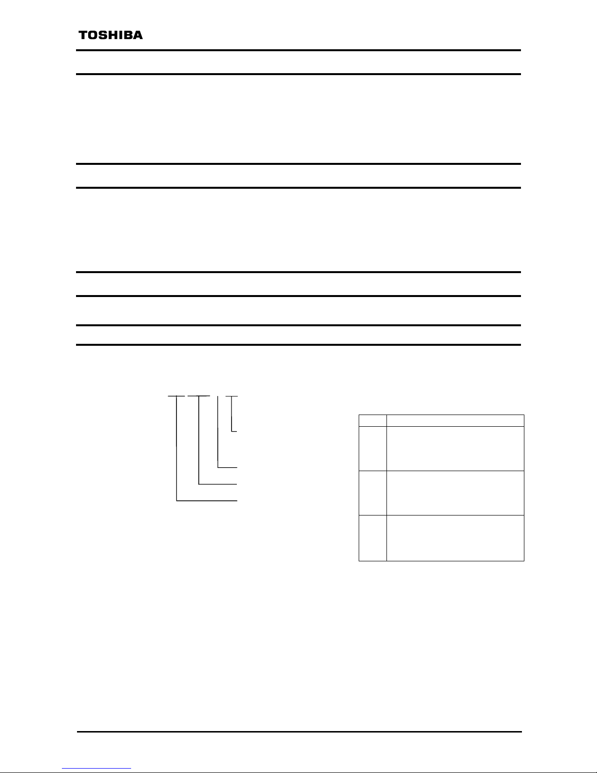
1.1. Type of the External Fin Attachment
The coded model name represents the type of the External Fin Attachment as explained
below.
AT FIN 7 *5
Attachable inverter model
*5 VFA7-2370P1〜2550P1
4370P1〜4750P1
VFP7-2370P〜2550P
4450P〜4900P
*6 VFA7-2750P1
4110KP1,4132KP1
VFP7-2750P
4110KP〜4160KP
*7 VFA7-2900P1
4160KP1〜4280KP1
VFP7-2900P,2110KP
4200KP〜4315KP
Attachment option
A7,P7用
External Fin Attachment
Attachable inverter model
(See the table on the right
hand.)
For A7 and P7
E6581187
-3-
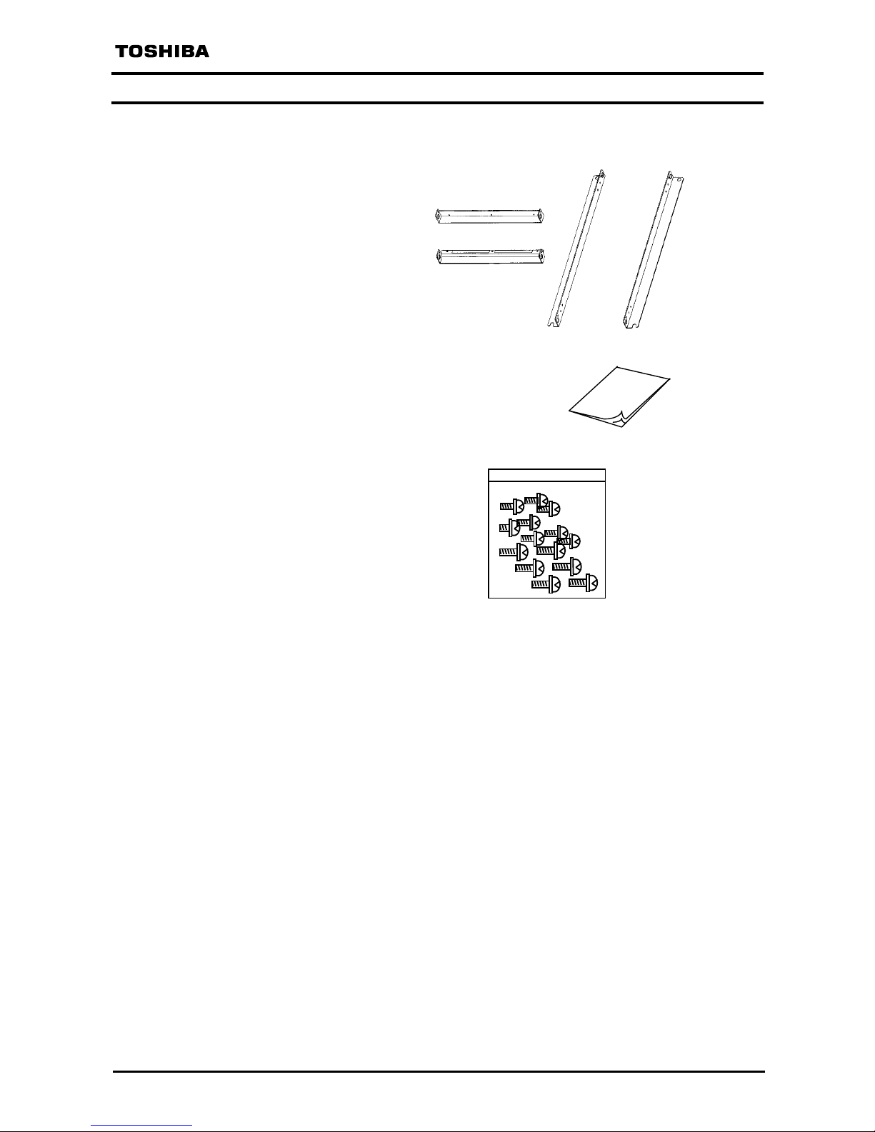
1.2. Checking contents of package
The External Fin Attachment comprises the following parts. Unpack and check to see if there are
the following things contained.
(1) Attachment ... 4 pcs
(2) Manual (this booklet) of the External Fin Attachment ... 1 copy
(E6581187)
(3) Set of screws to fit the attachment to the inverter ... 1 bag
Details of screws
M4X10 ... 10 pcs
M5X12 ... 15 pcs
M
a
n
u
a
l

E6581187
-4-
[2] Side attachments
2. Installation method
Before fitting the attachment to the inverter, switch off the power supply and make sure that
the charge lamp has gone out without fail. For details, refer to the “Safety Instructions”
appearing in the manual of the inverter.
2.1. In case of ATFIN7*5
Attachable inverter models
VFA7-2370P1, -2450P1, -2550P1, -4370P1, -4450P1, -4550P1, -4750P1
VFP7-2370P, -2450P, -2550P, -4450P, -4550P, 4750P, -4900P
Step 1: Remove the inverter fitting metal (4 pcs) shown in Figure 1 from the inverter.
Figure 1
Step 2: First, fit the top and bottom attachments (Figure 2 [1]) to the inverter, next fit the side
attachments (Figure 2 [2]) to the inverter with the screws supplied with the
attachment as shown in Figure 2.
(For fitting the bottom attachment, remove the front cover of the inverter
beforehand.)
Figure 2
M5×12
M5×12
Front cover
M4×10
[1] Top and bottom attachments
Among the screws supplied with the attachment,
the following screws remain as unused.
M4X10 screw ... 4 pcs, M5X12 screw ... 3 pcs
M4×10

E6581187
-5-
2.2. In case of ATFIN7*6
Attachable inverter models
VFA7-2750P1, -4110KP1, -4132KP1
VFP7-2750P, -4110KP, -4132KP, -4160KP
Step 1: Remove the inverter fitting metal ① (4 pcs),
hanging metal ② (2 pcs) and screw ③ (4 pcs)
shown in Figure 3 from the inverter.
Step 2: First, fit the top and bottom attachments to the inverter, next fit the side attachments to the inverter with
the screws supplied with the attachment as shown in Figure 4.
(For fitting the bottom attachment, remove the front cover of the inverter beforehand.)
[2] Top attachment
①
①
①
①
②
②
③
③
[1] Bottom attachment
M4×10
M5×12
Figure 3
[3] Side attachments
Reuse the screws ②
and ③ removed in
the step 1.
M5×12
M4×10
Figure 4
Among the screws supplied with the attachment,
the following screws remain as unused.
M4X10 screw ... 4 pcs, M5X12 screw ... 7 pcs

E6581187
-6-
2.3. In case of ATFIN7*7
Attachable inverter models
VFA7-2900P1, -4160KP1, -4220KP1, -4280KP1
VFP7-2900P, -2110KP, -4200KP, -4220KP, -4280KP, -4315KP
Step 1: Remove the inverter fitting metal ① (4 pcs),
hanging metal ② (2 pcs) and screw ③ (4 pcs)
shown in Figure 5 from the inverter.
Step 2: First, fit the top and bottom attachments to the inverter, next fit the side attachments to the inverter with
the screws supplied with the attachment as shown in Figure 6.
(For fitting the bottom attachment, remove the front cover of the inverter beforehand.)
M4×10
Figure 5
(3) Side attachments
Reuse the screws ②
and ③ removed in
the step 1.
M5×12
M5×12
Figure 6
Among the screws supplied with the attachment,
the following screws remain as unused.
M4X10 screw ... 2 pcs, M5X12 screw ... 7 pcs
(1) Bottom attachment
M4×10
(2) Top attachment
①
①
①
①
②
②
③
③

E6581187
-7-
3. Installation on panel
The following illustrates the cutout in the panel to install the inverter with the attachment.
(The size of the cutout in the panel is shown in mm.)
図5
ATFIN7*7
VFA7-2900P1, 4160KP1〜4280KP1
VFP7-2900P,2110KP, 4200KP〜4315KP
Common size (Refer to Figure 9.)
ATFIN7*5
VFA7-2370P1〜2550P1, 4370P1〜4750P1
VFP7-2370P〜2550P, 4450P〜4900P
Common size (Refer to Figure 7.)
ATFIN7*6
VFA7-2750P1, 4110KP1,4132KP1
VFP7-2750P, 4110KP〜4160KP
Common size (Refer to Figure 8.)
Figure 7
Figure 8
Figure 9

E6581187
-8-
4. Outward appearance
Outward appearances of the inverter with the attachment are roughly shown in Figure 10,
11 and 12. (Unit of size: mm)
Inside of panel
―――――――――
――――――――――――――――――
―――――――――
Outside of panel
ATFIN7*5
VFA7-2370P1〜2550P1, 4370P1〜4750P1
VFP7-2370P〜2550P, 4450P〜4900P
Common size (Refer to Figure 10.)
Figure 10

E6581187
-9-
ATFIN7*6
VFA7-2750P1, 4110KP1,4132KP1
VFP7-2750P, 4110KP〜4160KP
Common size (Refer to Figure 11.)
Inside of panel
―――――――――
――――――――――――――――――
―――――――――
Outside of panel
Figure 11

E6581187
-10-
図9
ATFIN7*7
VFA7-2900P1, 4160KP1〜4280KP1
VFP7-2900P,2110KP, 4200KP〜4315KP
Common size (Refer to Figure 12.)
Inside of panel
――――――――
――――――――――――――――
――――――――
Outside of panel
Figure 12
 Loading...