

Page 1

TOSHIBA
E6580516
High-Performance Inverter
Instruction Manual
TOSVERT VF-A5
200V
400V
1. Make sure that this Instruction Manual is delivered to the end
user of the inverter unit.
2. Read this manual before installing or operating the inverter
unit, and store it in a safe place for reference.
0.4
0.75
--55kW
~75kW
NOTICE
TOSHIBA CORPORATION
© 1994
Ver. no-'
Page 2

Safety Precautions
This inverter is for driving a 3-phase motor, and must not be used for other applications.
[I] Always observe the following items to prevent electrical shock.
1. Do not touch charged parts such as the terminal block while the CHARGE lamp is lit. A charge will still
be present in the electrolytic capacitors, and therefore, touching these areas may result in an electrical
shock. Always turn the inverter’s input power off before wiring the motor terminals. Walt at least five
minutes after the "CHARGE' lamp has gone out, and then confirm that the capacitors have fully
discharged by using a tester, etc., that can measure high-voltage DC.
2. Do not touch or insert a rod or any other item into the
inverter while power is applied (there are high voltage areas
on the PCB), as this may lead to electrical shock or inverter
damage.
(When operating with the cover removed, charged areas will
be exposed, so always install the unit inside a panel so that
it cannot be easily touched.)
Never attempt to modify the inverter unit.
3. Ground the unit’s G/E terminal and the motor. (Electric
shock may occur due to leakage currents.)
[n] Retry function
1. This inverter has a "retry function" that automatically resets the unit when a fault trip occurs. Observe the
following points when this function is selected.
Even if the inverter has fault tripped, take care to not get caught in the motor or equipment. When the
"retry function" is selected, the inverter will automatically start after the designated time. (Refer to page
78.)
Take special care when an overload trip occurs, as the "retry function" may activate after a delay of up
to 5min.
[m] Observe the following points to prevent fire.
->/7
Ijili
'I
1111
llll
L=y
Control section
(W/hen cover is removed)
/
High voltage area
1. Confirm the inverter’s rating nameplate, and connect a 3-phase input power source within the rated range
to the RA.1, S/L2, and TA- 3 power source terminals.
If an Incorrectly-rated power source is connected to the inverter, such as when a 400V power source is
connected to a 200V inverter, the inverter’s internal components may explode.
2. No fuse is contained in the inverter, so instail a suitable non-fuse breaker (MCCB) on the inverter’s input
power source.
(Refer to Table 5-1 on page 14 for Examples of selecting equipment for wiring.)
[IV] Refer to the following chapters for other precautions.
Chapter 1 Acceptance Inspection and Precautions
Chapter 2 Installation Precautions Page 2
Chapter 4 Cperation Precautions Page 5
Chapter 5 Wiring Precautions Page 9
Chapter 12 Maintenance and Inspection Page 102
....
Page 1
Page 3

introduction
Thank you for purchasing the Toshiba High-Performance Inverter TOSVERT VF-A5'.
The *VF-A5" inverter has many various functions built in for use with a 3-phase induction motor. All Operations
of this unit are done via the easy-to-use keyboard-type operation panel. A blind function (Refer to page 50) that
dispiays only those functions required for operation, and an edit function (Refer to page 29) that automatically
collects parameters that differ from their defauit settings are used to make basic operation and setting easier.
Advanced control technology features (sensorless vector control, feedback control, current limit, retry, and stall
prevention functions) are built in, so that the inverter wiil not trip easily, and will provide unparaileied reliability.
Please read this manual thoroughly before use to properly understand the correct use of the outstanding
functions of the 'VF-A5'.
This manual should be stored by the user of the *VF-A5* for reference during maintenance and inspection.
Symbois used in this manual are as shown below. Understand them before reading this manual.
1. LED display character codes; Refer to page 123
2. To indicate a parameter display on the operation panel in this manual:
Example rWcT~t
To indicate a panel key:
Example ENTER key
The box
Note) The box
is not used when indicating parameter group names and parameter settings.
is not used when displaying parameters in tables.
Page 4

Table of Contents
1. Acceptance Inspection and Precautions ...................................................... 1
2. Installation Precautions ................................................................................. 2
3. External View and Component Names
4. Operation Precautions .................................................................................... 5
5. Wiring Precautions
.........................................................................................
6. Standard Connections ................................................................................. 15
6.1 Standard Connection Example ............................................................................... 15
6.2 Terminal Functions ................................................................................................... 18
7. Operation and Adjustment ............................................................... 27
7.1 Operation Panel ........................................................................................................ 27
7.2 Basic Operation ...................................................................................................... 28
7.3 Operation Modes ................................................................................................. 32
7.3.1 Standard Monitor Mode ....................................................................... 32
7.3.2 Status Monitor Mode ............................................................................ 35
7.3.3 Settings Monitor Mode
7.3.4 JOG Run Mode
7.4 Operation Mode Selection ....................................................................................... 40
7.4.1 Operation Mode Changeover .................................................................. 40
7.4.2 Run/stop Command [ cnod in Cr.ut ] ............................................. 40
7.4.3 Frequency Command Source Setting Function
[ FnOd in Cr.ut ] 40
7.4.4 Parameter Setting Function [ pnod in Cr-.ufc ] ... 41
7.4.5 Standard Parameter Value Reset Function
[ I h HP I in Hr.ut ]
7.4.6 Selection of Stopping Method from the Panel
7.4.7 Fault Reset ................................................................................................. 44
.........................................................................................
8. Parameter Explanations ............................................................................... 45
1. c r.F V/f settings .......................................................................................... 45
V/f pattern ® ..................................................................................... 46
V/f pattern 0 ..................................................................................... 47
Acceleration/deceleration time settings
Acc/Dec patterns, Acc/Dec pattern adjustment,
Low/High .......................................................................................... 49
Blind function selection
Upper limit/lower limit frequencies
Reverse operation disable selection ............................................ 51
.......................................................
.............................................................................
.........................................................
..................................
.......................................
.................................................................
..............................................
42
43
3
9
36
39
48
50
51
-1 -
Page 5

2. Cr.Pn Acc/dec #1 and #2 selection
.............................
.............. 52
Panel feedback control ................................................................ 53
Panel reset selection ................................................................... 53
Fundamental parameter switching............................................... 54
3. C t-.S t Input terminal selections 0 ............................................................ 55
Input terminal selections 0
.........................................
56
Output terminal selections 0 ................................................... 57
Output terminal selections 0 ........................................................ 58
Low speed, acceleration/deceleration
complete, speed reach output signals.......................................... 59
Input/output terminal response time selections .... 60
Commercial power/lNV switching ............................................... 61
Output terminal pulse frequency selection
RR input special function selection
........................................
.............................
62
62
4. Or.BC Run frequency control .................................................................. 63
Start-up frequency/End frequency................................................ 64
Jump frequencies........................................................................ 65
PWM carrier frequency ............................................................... 66
5. Cr-.SF Preset speed operation 0 .............................................................. 67
Preset speed operation 0
............................................................
68
Frequency priority selections ...................................................... 69
Jogging operation ....................................................................... 70
Frequency setting input signal characteristics ............................ 71
6. Cr-.Pr- Electronic thermal protection 0 ..................................................... 72
Electronic thermal protection 0
...................................................
73
DC injection braking settings 0 ............................................... 74
DC injection braking settings 0 .................................................... 76
Dynamic braking operation
Emergency stop
..........................................................................
........................................................
77
78
Retry function ............................................................................. 78
Regeneration power ride-through control
...................................
79
Auto-restart ................................................................................. 79
Trip function selections ............................................................... 80
Output short circuit detection selection ....................................... 80
Fault trip saving .......................................................................... 81
7. Cr.Pt Pattern run 0................................................................................. 82
Pattern run 0 ............................................................................... 83
- II -
Page 6

8. Cr.ufc Panel operation permission
Industrial application parameters selection
.........................................................
...........................
84
85
Standard setting mode selection ................................................ 85
Command/frequency mode selections ....................................... 86'
Status monitor display selections
Blind function selection
.............................................................
..............................................
87
87
Units settings ............................................................................. 88
9. Cr-.on Meter adjustment parameters ............................................................ 89
9. Device Specifications ............................................................................................. 90
9.1 Model and Standard Specifications..................................................................... 90
9.2 External Dimensions........................................................................................... 93
10. Options ..................................................................................................................... 95
11. Error Displays and Troubleshooting
.....................................................................
97
11.1 Inverter Trip Causes and Remedies .................................................................. 97
11.2 Other Fault Troubleshooting
...........................................................................
101
12. Maintenance and Inspection ................................................................................ 102
12.1 Preventive Maintenance and Periodic Inspection
12.2 Component Replacement
................................................................................
.............................................
102
103
13. Storage .................................................................................................................... 104
14. Warranty .................................................................................................................. 104
Appendix
Appendix Table 1. Parameter list ............................................................................. 105
Appendix Table 2. List of trips ................................................................................. 121
Appendix Figure 1. Input terminal information ......................................................... 122
Appendix Figure 2. Output terminal information ...................................................... 122
Appendix Figure 3. Character codes ....................................................................... 123
Appendix Table 3. Standard default settings per inverter capacity ... 124
Appendix Table 4. Industrial application parameters
..................................................
125
Appendix Table 5. Changed settings memo ............................................................ 142
- Ill
Page 7

1. Acceptance Inspection and Precautions
(1) Confirm that the unit has not been damaged during shipment.
(2) Confirm that the model noted on the rating nameplate is as ordered.
(3) Whpn storing the unit temporarily after purchase, store it in dust-free, well-ventilated location.
(4) Special care is taken during product manufacturing, packaging, and shipment. If any problems are
discovered, however, please contact your dealer immediately.
Details of rating nameplate
Applicable —
power source
Capacity —
Rated output
voltage
Details of model No.
SOURCE 200-220V-50HZ
CAPACITY 6. 5 kVA
LOT NO. i
0UtSS4«91PC 3 MADE IN JAPAN
Type
r
------------V
A.
K
TRANSISTOR INVERTER
TYPE-FORM VFA5- 2037 P
FREQUENCY 0. l~80Hz
200<-230V-eOife
( 0. Ol-iOO) Hz
CURRENT 16. 5 A
VOLTS 200-23OV
r----------------------
AC MOTOR 3. 7 kW MAX.
--------------------------------------- ., I
TOSHIBA CORPORATION
Model No.
Model
n
2
5
O
3
p Y
T
J
----------------
11 I
Option PCB
and special
codes
A
2 2
Inverter model
<
-----
Rated output frequency
<
-----
Rated output current
<— Applicable motor capacity
,
Model name
TOSVERT
VF-A5 series
A: General pur
pose highperformance
Input voMage
2; 200V-230V
4: 380V-460V
8: DC power source
input
(200V class output)
9: DC power source
input
(400V class output)
Standard
motor
capacity
0.4kW : 004
0.75kW; OOr
1.5kW : 015
2.2kW : 022
3.7kW : 037
5.5kW ; 055
7.5kW : 075
IlkW : 110
15kW : 150
18.5kW: 185
22kW : 220
30kW :300
37kW :370
45kW : 450
55kW : 550
75kW ; 750
Additional
functions
E: Fully enclosed
F: External
heatsink
N: GTR7
modification
Y: Other
(nonstandard)
None: Standard
Operation
panel
P: Installed
B; Not installed
UL-listed;
UP, UB
Option PCB and special specification codes
AOD: Special specification code (OD are numbers)
M: 12-bit binary input PCB 4526A installed
Q: Expansion terminal block PCB 4514A installed
R: Expansion terminal block PCB 4514B installed
S: Expansion terminal block PCB 4514C installed
T: Expansion terminal block PCB 4514D installed
J: Expansion terminal block PCB 4515A installed
K: Expansion terminal block PCB 4515B installed
D: Expansion terminal block PCB 4515C installed
V: RS485 communication PCB installed
W: TOSLINE-FIO communication PCB installed
X; TOSLINE-S20 communication PCB installed
- 1 -
Page 8

2. installation Precautions
This inverter is an electronic control unit. Take special care concerning the installation environment.
Confirm that the input power is within ±10% of the rated value. If the input power voltage range
tolerances are exceeded during use, the protective circuits may function or the inverter may be
damaged.
Avoid instaliation in hot and humid locations,
where condensation or freezing may occur, or
where water, dust, or metal chips may come into
contact with the inverter.
Install in a location
free of corrosive gases
or cutting fluids, etc.
Do not install the unit
in locations that
experience large
vibrations.
Ground the G/E
terminal to prevent
electrical shock and
Attach the unit to a non-combustible material such as a metal panel. To
ensure adequate ventilation, maintain the following installation spaces, and
always install the unit vertically in the longitudinal direction. When instailing
malfunction due to
noise.
ua/iL
10cm or more
5cm or more
5cm or more
ri
10cm or more
7777777 ‘
Use the unit within an ambient temperature of
-10 to 40°C.
Because the inverter radiates
heat, when installing in a
panel take special care
concerning ventilation and
panel space. Removal of
the cover is recommended
when using in a panel to
ensure maximum longevity
and reliability.
The inverter may malfunction if the
following types of devices are
installed nearby, so use proper
precautions.
• Solenoids ■
• Brakes
• Electromagnetio contactors
- Ruorescent iights
> Resistors
---------
- Install a surge killer
on the exciting coil.
Keep away from the inverter
multiple inverters in a row, leave a clearance of
at least 10cm between each unit. This clearance
can be reduced depending on the environment
or by adding fans.
g
(For 37kW and larger units, leave a clearance of
at least 20cm above and below the inverter to
allow for fan replacement and wire bending
space.)
Contact the Engineering Department for further
details.
Inverter life depends greatly on the ambient temperature. Make sure
that the ambient temperature of the installation location does not exceed the
maximum ambient temperature rating (40°C). ^
Measure the temperature at the positions shown in the diagram on the right,
and confirm that it is less than the maximum ambient temperature rating
(40°C). (50°C or less when the cover is removed.)
22kW and larger units can be used up to an ambient temperature of 50°C.
(Do not remove the cover from 22kW and larger units.)
* Always install the inverter in the longitudinal direction on a vertical surface.
- 2
Sett
Measurement position
Measurement position
Page 9
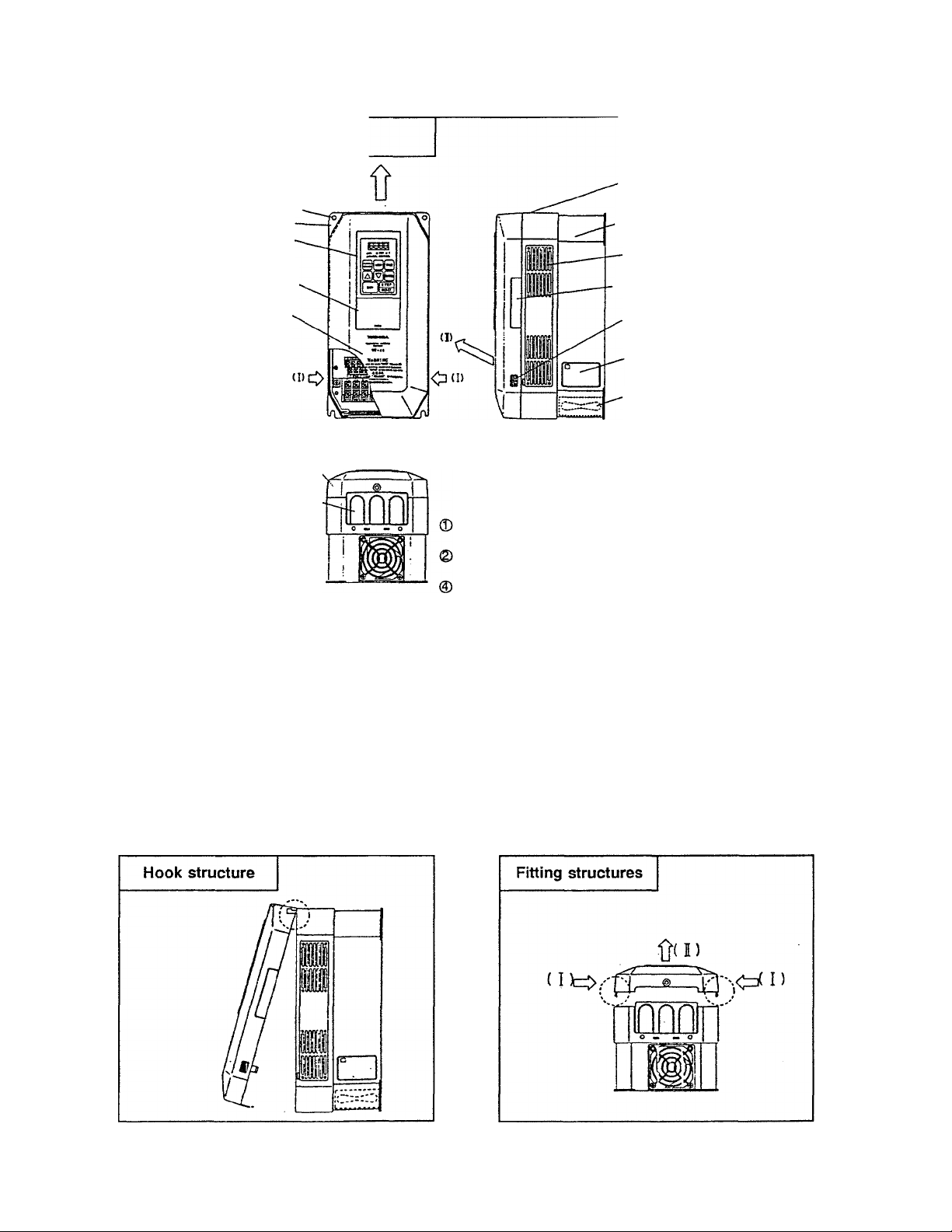
3. External View and Component Names
3.1 Component Explanation (I)
0 Cooling air exhaust port
® Mounting hole (4 holes)
® Mounting bracket
® Operating panel
® ROM interface window
(semi-transparent)
® Front cover warnings
@ Cover (plastic)
©) Wiring access plate: '
Always cut out the wiring
ports as necessary.
When using an 11kWor larger unit,
make slits in the rubber bushing
with nippers or a knife as
shown below.
© Upper caution sticker;
Always remove this sticker when the ambient
temperature is high.
® Ventilation slots:
A cover-up plate option is available for fully-sealed
applications.
_ \
Slit
Rubber
bushing
© Upper caution sticker
® Chassis (plastic)
© Ventilation slots
0 Optical cable access slot
for installation of optical
communication options.
© Finger clasp for
removing cover
O Rating nameplate
© Cooling fan
Operating panel: removable
Refer to section 3.3 Removal of operating panel.
ROM interface window: removable
Refer to section 3.3 Removal of ROM interface window.
Cover
Always read the cautions ® on the front of the cover and remove
the cover when wiring.
Refer to section 3.2 Removal of cover.
H the ambient temperature of the inverter unit exceeds 40°C when
mounted in a panel, remove the cover. The unit can then be used
up to a temperature of 50°C.
3.2 Removal of Cover
1)
For 7.5kW and smaller... Place your fingers on the finger clasps for removing the cover shown In the 3.1 Component Explanation
(I) drawing. Apply force in the direction of the arrows (1), and pull the cover up in the direction of arrow
(n). The cover will come off.
For 11~18kW... Remove the two screws on the cover wiring iniet, and then remove the cover like the 7.5kW models.
For 22kW and larger... Wait for the "CHARGE* lamp on the cover (sheet metal) to go out. Then remove the four screws holding
the cover (six screws for 37kW and larger), and the cover will come off.
- 3 -
Page 10
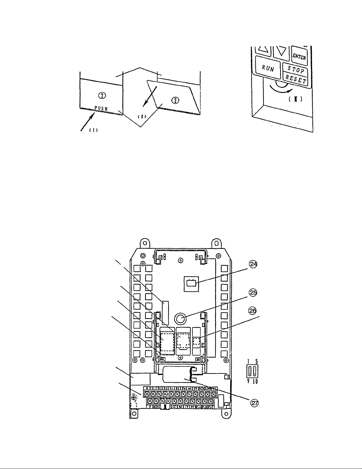
3.3 Removal of the ROM Interface
Window and Operation Panei
Operation panel
ROM interface window
(I) Press where the word PUSH is located.
I
The top of the window will open.
1
(n) Hold the top of the window, and
pull it out in the direction of
the arrow (II).
( iV )
(m) The operation panel attachment
screw can now be seen. Turn it
in the direction of the arrow
(HI) until it completely
loosens.
(TV) When the screw has
completely loosened, pull the
operation panel out in the direction
of the arrow (TV).
3.4 Component Explanation (II)
@ Option connector
(40-pin)
^ RS232C communicatioiY
connector
(Modular 6-pin)
@ Option ROM socket
ROM cover
Option connector
(20-pin)
Control terminal block
Operation panel
connector
Operation panel
attachment stud
Changeover switch for
frequency setting
signal inputs
IV terminal l/V changeover switch
RX terminal 10V/5V changeover switch
- 4 -
Flat cable
(for control terminal block)
Page 11

4. Operation Precautions
Observe the following points when using the VF-A5 inverter
4.1 Cautions Regarding Motor
Comparison with com
mercial power source
operation:
Running at low-speeds:
Adjustment of overload
protection level:
Running at speeds
exceeding 60Hz:
The VF-A5 inverter uses a sinusoidal-wave PWM method, but the
output voltage and output currertt will be distorted waveforms which
closely approximate sinusoidal waveforms, instead of complete
sinusoidal waveforms. In comparison to operating with the commercial
power source, the motor temperature rise, noise and vibration will
increase slightly.
When the inverter is used in combination with a general purpose
motor and run at low speeds, the motor’s cooling effect will decrease.
Therefore, the output load must be reduced to less than the rated
load. If the motor is to be run at the rated torque even at low speeds,
use a Toshiba 'VF motor* specially designed for use with inverters.
When used with a VF motor, the inverter’s overload protection level
must be adjusted. (Refer to pages 72, 73 for details.)
When using this inverter with a general purpose motor, the overload
protection of the VF-A5 is performed by use of an overioad detection
circuit (electronic thermal relay) that meets a general purpose motor’s
reduced load characteristics. The reference current value for this
electronic thermal relay is set to the inverter’s rated current value;
therefore, this may need adjustment depending on the motor.
When operating at a frequency that exceeds 60Hz, motor vibration
and noise wiil increase. Furthermore, this type of operation may be
limited by the motor’s mechanical strength and bearing construction,
so please contact the motor manufacturer for further information.
Load equipment lubrication
method:
Ultra-light loads and lowinertia loads:
Measures for instability
phenomena:
When driving an oil-lubricated speed reduction gear or geared motor,
the lubrication may deteriorate at low-speeds, so contact the speed
reduction gear manufacturer for information on usable variable-speed
areas.
Instability phenomena, such as abnormal vibration or overcurrent
trips, may occur when operating with an ultra-light load at a load ratio
of 5% or less, or with a load having an extremely small moment of
inertia In these cases, lower the carrier frequency. (Refer to page 66)
Instability phenomena may also occur when using the inverter with the
following types of motors or loads, so always confirm applicability
before use.
(1) Combination with motor exceeding recommended applicable
motor rating.
(2) Combination with special motors such as explosion-proof motors.
(3) Combination with special loads having severe rotational
fluctuations, such as piston-type movements.
- 5 -
Page 12

Braking during power off:
The inverter will enter the coast-stop state when the power source is
turned off. The motor will therefore not stop immediately. To stop the
motor immediately, install an auxiliary brake unit. Dynamic braking
units and mechanical braking units are available, so select one that
suits your specific appiication.
Loads that generate a
negative torque:
Motors with brakes:
The overvoltage protection or overcurrent protection may function and
trip the inverter when used with loads that generate a negative torque,
in this case, a braking resistor that meets the load condition must be
instalied.
If a motor with a brake is directly connected to the inverter, the
voltage when the motor is started will be low, which may result in the
brake not being released. In this case, separately wire the brake
circuit and motor main circuit. In addition, there is a delay in the time
to when the inverter output stops if the inverter’s ST to CC control
terminal connection is released, so use of the circuit configuration in
Fig. 4-1 is recommended.
In Fig. (a), the brake power is turned ON and OFF via MC2 and MC3.
If a circuit configuration as shown in the drawing is not used, a bound
current may flow during braking and may cause an overcurrent trip.
The brake power can also be turned ON and OFF using the low-
speed signal LOW as shown in Fig. (b).
(Non-excited brake)
Fig.4.1 Circuit configuration for motor with brake
In some cases, such as in hoist applications, turning the brake ON and
OFF by using low-speed detection (LOW terminal function) may be better,
so contact your dealer for further details.
4.2 Cautions Regarding the inverter
Inverter’s overcurrent
protection:
Overcurrent protection is used as the VF-A5 inverter’s protection
function, and the current setting level is set to match the largest
applicable motor. Therefore, when operating a motor that is smaller
than the inverter capacity, the overcurrent level and electronic thermal
protection parameters must be readjusted. (Refer to pages 72, 73.)
Page 13
Running with light loads:
Operating a large capacity motor with a light load using a small
capacity (kVA) inverter must be avoided. The output peak current will
increase due to the current ripple, and overcurrent trips may
frequently occur.
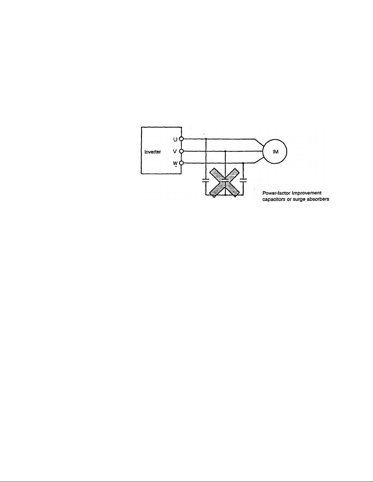
Power-factor improvement
capacitors;
Use with voltage sources
other than the rated voltage:
Protection device for
lightning surges:
Power-factor improvement capacitors must not be installed on the
inverter’s output. When operating a motor with power-factor
improvement capacitors installed, remove the capacitors, or the
inverter may fault trip or the capacitors may be damaged.
Use with voltage sources other than the rated voltage is not possible.
If necessary, use a transformer, etc., to increase or decrease the
source voltage to the rated voltage.
A DSA (lightning surge absorber) is used for protection in the unit. If a
surge voltage exceeding 2600 to 3600V peak is applied, the device
will light like a glowing electrical discharge. This will cause no
problems if the condition does not continue for an extended period of
time.
(Refer to Fig. 6-2-1 Fig. ® on page 21.)
7 -
Page 14
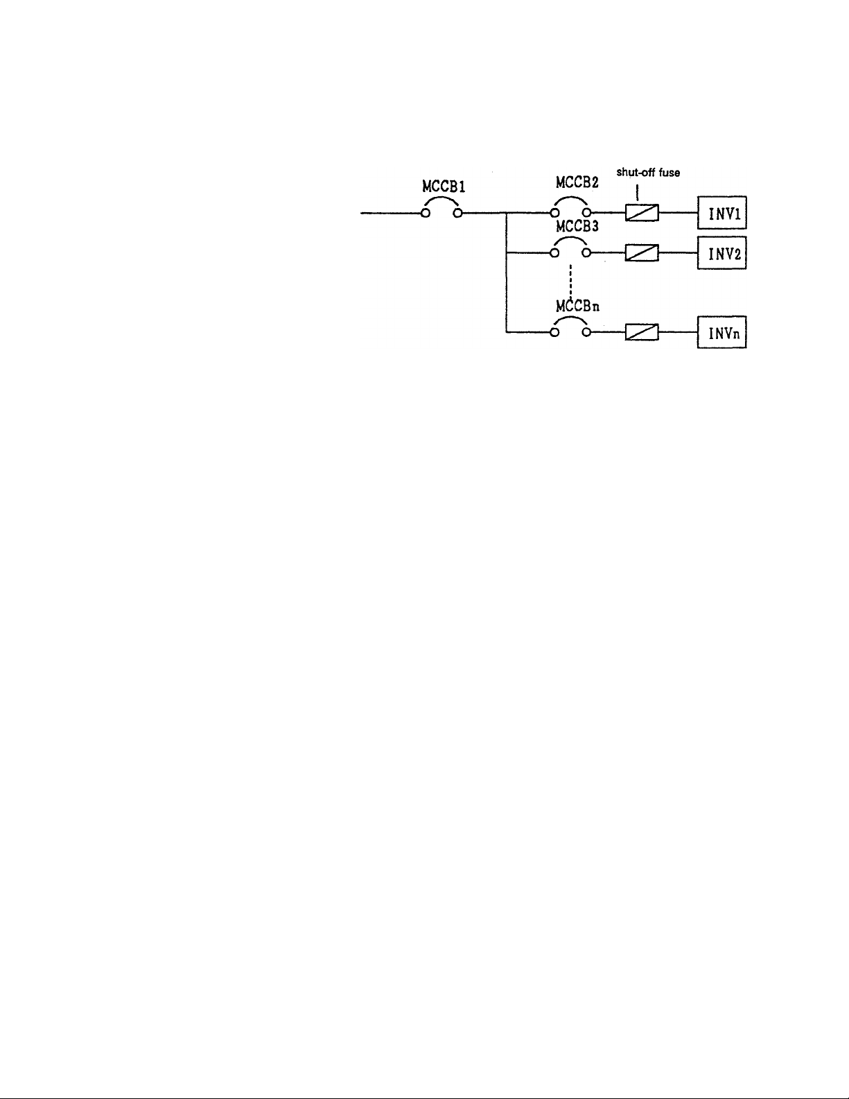
Use of multiple inverter
units:
Observe the following points when using multiple inverter units on the
same power source line.
High-speed
As Shown above, there is no fuse installed in the inverter’s main
circuit, if a short circuit fault occurs in the inverter, not only MCCB2
will trip, but the main breaker MCCB1 may also trip.
Select the shut-off characteristics of MCCB1 and MCCB2 so that a
selective shutdown can be executed and only MCCB2 trips. If the
optimum characteristics cannot be selected, install a high-speed shut
off fuse after MCCB2. (Refer to page 14 for MCCB selection.)
4.3 Inverter Disposal Precautions
Observe the following points when disposing of the inverter.
Explosions from
incineration:
Gasses from plastics:
Disposal method:
Placing the inverter in an incinerator may be dangerous, as the
electrolytic fluid used in the electrolytic capacitors may expand and
explode.
The plastic used for the cover, etc., may generate poisonous gases
when incinerated.
Commission the disposal of the inverter to a specialist.
- ft -
Page 15

5. Wiring Precautions
5.1 Connection to Main Circuit (Refer to page 11, Fig. 5.1.)
Observe the following precautions when making connections to the inverter.
Confirmation of power OFF:
Electrical shock preventionconfirmation of charge
dissipation:
Confirmation of main circuit
connections:
Separation of power source
and motor wiring:
Separation of control and
main power supplies:
Always turn the primary power distribution panel switch OFF, and
confirm with a tester that a voltage is not present before beginning
wiring to the inverter.
Before changing the wiring, wait at least five minutes after the
•CHARGE“ lamp inside the inverter has gone out, and then confirm
that the capacitors have fully discharged by using a tester, etc., that
can measure high-voltage DC. The internal electrolytic capacitors are
charged, and there is a danger of electrical shock If the charged
areas are touched while the "CHARGE' lamp is on. Do not touch the
terminal block or remove the upper cover while the lamp is lit
The inverter will be damaged If the input power source is applied to
the motor terminals (U/T1, V/T2, W/T3). Always confirm the wiring for
the power source terminals (R/L1, S/L2, T/L3) and motor terminals
(U/T1, V/T2, W/T3) before turning the power on.
To prevent problems due to radio-frequency noise, etc., do not bundle
the wiring to the input power terminals (R/L1, S/L2, T/L3) and the
motor terminals (U/T1, V/T2, VJfTS) together.
In order to maintain the control power supply to display faults or to
operate the communication options while the main circuit power is
shut down, remove the two shorting bars (between R/L1-R0, S/L2-S0)
on the control power supply terminal block. Connect the control
power to a power source that is separate from the main circuit supply.
5.2 Connection of Control Signals
Observe the following points when making control signal connections.
Rating of relay contacts:
Power wiring for control
circuit:
Control wiring wire sizes:
Isolation from main circuit:
Use a relay intended for use with micro-current (min. applicable load
rating less than 4mA-24V.), and install a surge killer on the relay’s
exciting coil.
Use shielded wiring or twisted-pair wiring for the control circuit, and
separate the wiring from the main circuit wiring.
The following wiring sizes for the control circuit are recommended.
Frequency setting signal input, frequency meter, ammeter: shielded
wire that is 0.3mm® or larger
Other signals: Vinyl-insulated wire that is 0.75mm® or larger
All control terminals other than FLA, FLB and FLC are connected to
Internal electronic circuits, so input signals must always be electrically
isolated from the main circuit.
9-
Page 16

Ratings of connected
meters:
Connect a full-scale 1 mAdc DC ammeter or full-scale 7.5Vdc-1 mA DC
voltmeter to the control terminals.
Rating of FL signal contacts:
External use of control
power:
Open collector outputs:
Frequency-setting
potentiometer:
5.3 Other Precautions
Use of crimp-on terminal
lugs:
The contact rating of the protection operation detection relay (FL) is
250Vac (cos0=O.4) 30Vdc-1A.
A max. of 24Vdc-100mA can be used from the P24 control power
terminal to drive external relays.
The RCH and LOW control terminals are open-collector outputs, and
can output a max. 24Vdc-50mA. Use of a 24Vdc OMRON MY1 relay
(RY) is recommended.
Always install a diode (200V-1A class)
for surge absorption. Take special note
of the diode polarity to avoid incorrect
application.
Use a potentiometer rated at 1k to 10kO-1/4W for the frequency
setting Input signal.
The clearance between terminals on the inverter main circuit terminal
block is small, so use sleeved crimp-on terminal lugs for all main
circuit terminals. Take special care during connection so that the
terminal lugs do not make contact with neighboring terminal lugs.
P2<
RCH
Grounding terminal:
Built-in braking resistor
Internally-connected (E)
terminal:
The main circuit wiring is shown in Fig. 5.1.
(For 3.7kW or less, not showing control power terminals RO, SO)
Always ground the G/E grounding terminal with a wire that is 3.5mm®
or larger.
For inverter capacities that are 3.7kW or less, a built-in braking
resistor is connected between the main circuit terminals (PA1) and
(PB1), providing dynamic braking as a standard feature.
The (E) terminal is for internal connections, so do not remove
connections from it or make any external connections to it.
-10 -
Page 17
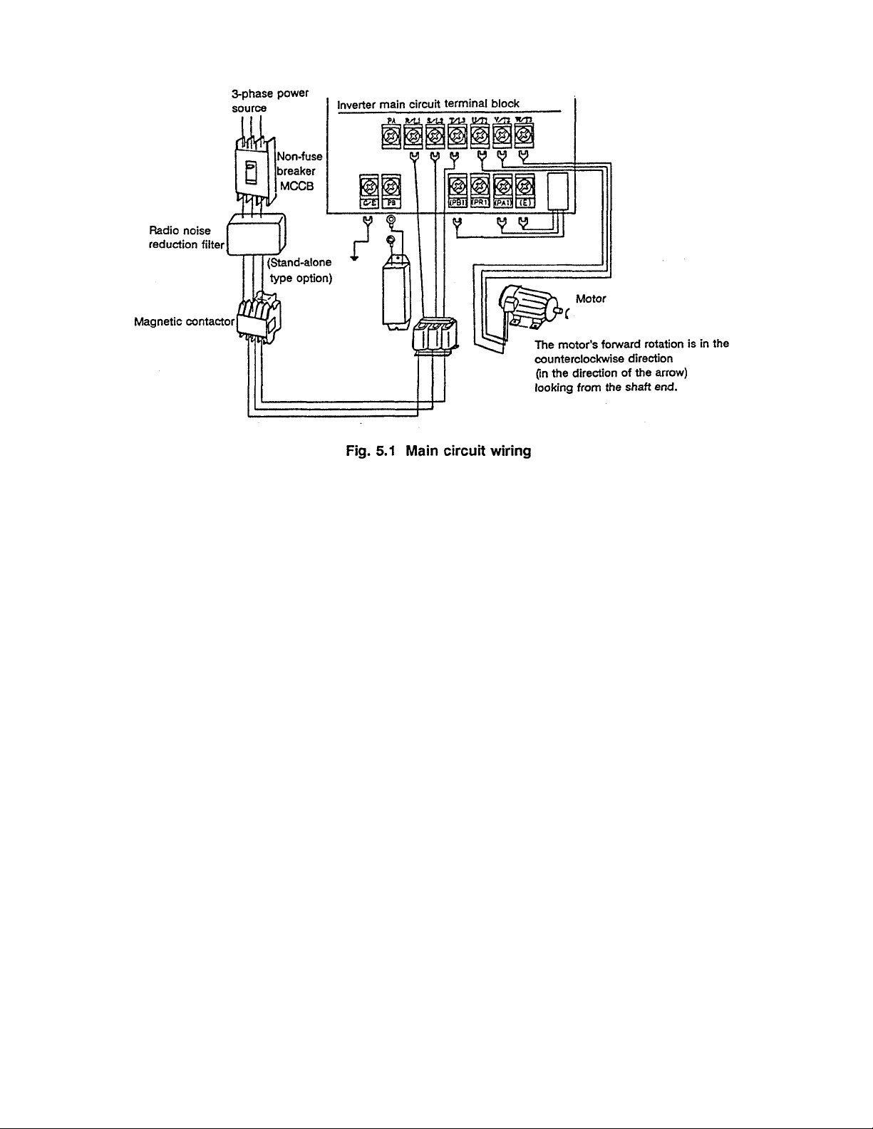
Note) A DC reactor (stand-alone type option) can be installed on 5.5kW and larger units. (Refer to the
function of main circuit terminals PO and PA on page 18.)
Installation of non-fuse breaker
(1) Install a non-fuse breaker (MCCB) for wiring protection on the input power source side.
(2) Avoid frequent starting/stopping by turning the non-fuse breaker ON and OFF.
(3) Start and stop by turning terminals F to CC (or R to CC) ON and OFF.
Installation of primary magnetic contactor
(Refer to page 14; Examples of selecting equipment for wiring.)
(1) When using an external braking resistor, install a magnetic contactor (MC) or non-fuse breaker with
trip coil (MCCB) on the inverter's power supply input side for protection. Make sure that the power
circuit can be opened with the built-in fault detection relay (FL).
(2) The VF-A5 has a built-in fault detection relay (FL). Connect the contacts of this relay to the primary side
magnetic contactor (MC) operation terminals, so that the MC can be opened when the inverter’s
protection circuit functions.
The fault detection relay (FL) contacts (250VAC-1A cos0=O.4) can be directly connected on 200V
systems. When using a 400V system, a transformer must be used to create 200V or less for the FL
sequence.
If the MC exciting current exceeds the FL contact rating, install another relay step.
(3) Turn terminal F (or R) to CC ON and OFF to frequently start and stop. Due to repeated inrush currents
when the power is turned on, the life of the inverter will be shortened when the primary magnetic
contactor is used to start and stop, so do not use this method to start and stop frequently.
(4) Install a surge killer on the magnetic contactor (MC) exciting coil.
-11
Page 18
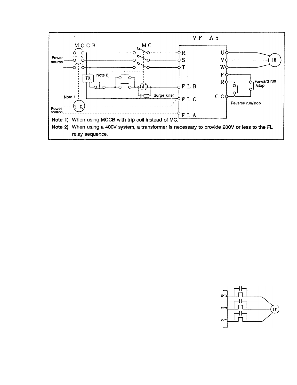
Fig. 5.2 Wiring example using a magnetic contactor
installation restrictions of secondary-side magnetic contactors
(1) As a rule, if a magnetic contactor is installed between the inverter and motor, do not turn it ON/OFF
while running. (If the secondary-side contactor is turned ON and OFF while running, a large current
may flow in the inverter, causing inverter damage and failure.)
(2) A magnetic contactor may be installed to change the motor or to change to the commercial power
source when the inverter is stopped. Always use an interlock with the magnetic contactor in this
situation so that the commercial power supply is not applied to the inverter’s output terminals.
Installation of overload relay (thermal relay)
(Refer to page 14; Examples of selecting equipment for wiring.)
(1) The VF-A5 has a built-in overload protection function that uses an electronic thermal relay. However,
in the following cases, the thermal relay operation level must be adjusted or an overload relay matching
the motor’s characteristics must be installed between the inverter and motor.
0When using a motor having a rated current value different from a Toshiba general-purpose motor.
(Adjust the electronic thermal level)
©When running a single motor with an output less than the specified standard applicable motor, or
when running several motor simultaneously (An overload relay must be installed on each motor.)
Note) If the motor cables for a 400V class inverter are long, the thermal
relay may malfunction. In this case, lower the carrier frequency (refer
to adjustment parameters on page 66), or install a 0.1/r to O.SpF-
1000V film capacitor between the input/output terminals of each
phase’s thermal relay.
< Example > When using external thermal relays, the inverter can be externally fault-tripped and
immediately stopped by using the following method (Fig. 5.3).
12
Page 19

Note) In this case, ensure that S4 is set to 'Emergency
stop function", by setting | /h H [in
0 r. 5 h to ID.
If the Th-Ry functions, the inverter will display
• E ', and fault trip.
* Other unused terminals can also be used instead of the S4
terminal.
Fig. 5.3 Wiring example using external thermal relays
C r. 51 etc., indicate the LED display on the operation panel. (Refer to Appendix 3, Character
codes, on page 123. The boxed items indicate a parameter or panel operation key.
When using the VF-A5 to drive a Toshiba VF motor*, designed exclusively for constant torque/inverter-
(2)
driven applications, set the electronic thermal protection characteristics for a VF motor.
(Refer to pages 72, 73, Electronic Thermal Protection.)
For protection measures, use of a motor with an imbedded-type thermal relay in the motor coil is
(3)
recommended when running a motor at low speeds.
Restrictions on the installation of power-factor improvement capacitors (both input/output)
Do not install power-factor improvement capacitors on the input or output sides of the inverter. Large
currents containing high frequency elements may flow to the capacitors and adversely affect them.
Capacitors on the output side may cause the inverter to overcurrent trip. Install an input reactor or De
link reactor (optional) for power-factor improvement.
Countermeasures against radio wave interference
The inverter may cause radio wave interference to audio equipment, etc., used near the inverter. In this
case, install a radio noise reduction filter (optional) on the inverter’s power source side, or shield the
cables to the motor with a conduit to reduce the interference. Contact your dealer for further details.
Cautions concerning ground faults
Verify that there are no incorrect connections between the motor and inverter and that there are no
short circuits in the motor before beginning operation. Do not ground the neutral point of a starconnected motor.
Installation of an input reactor
An input reactor can be used to improve the input power-factor, to suppress high harmonic elements,
and to miminize the risk of damage to the inverter that may be caused by sudden power fluctuations.
Always install an input reactor when connecting the inverter to the following types of systems.
(1) When power source capacity is SOOkVA or more, and when power source capacity is greater than
the inverter capacity by a factor of 10 times or more.
When connecting the inverter to the same power system as thyristor-commutated control
(2)
equipment.
When connecting the inverter to the same power system as a distorted-wave generation source,
(3)
such as an arc furnace or thyristor-switched converter unit.
Leakage currents
Leakage currents may increase slightly depending on the connection method.
(1) When multiple inverters are connected to one ELCB, increase the ELCB current sensitivity value.
(2) Keep the wiring length between the inverter and motor as short as possible.
(3) Use an ELCB with high-harmonic suppression.
-13
Page 20

Voltage
dass
200V
class
400V
class
Appncabfe
motor
m
0.4
0.75
1.5
2.2
3.7
5.5 -2055P
7.5 -2075P
11
15 -2150P
18.5 -2185P
22 -2220P
30 -2300P 200
37
45 -2450P
55 -2550P
75 -2750P
0.75
1.5 -4015P 10
2.2
3.7
5.5
7.5 -4075P
11
15 -4150P 60
18.5
22
30
37
45 -4450P 150
55
75
Inverter
Model
-2004P
-2007P 10
-2015P 15
-2022P
-2037P 30
-211 OP
-2370P
-4007P
-4022P 10
-4037P 15
-4055P
-4110P
-4185P 75
-4220P
-4300P
-4370P
-4550P
-4750P 225
Table 5.1: Examples of selecting equipment for wiring
Non-fuse breaker
(MCC8)
Rated
current
Toshiba
(A)
model
SS30
5
SS30
SS30
20 SS30
SS30 18
ESSO
50
EH100
60
EH100
100
125 EH225
EH225
125
EH225 93
150
EH225
EH225 180
225
EH400
250
EH400 220
250
500 SH600
SS30
5
SS30 9
SS30
SS30 9
SS30
30
30 SS30
ESSO 33 C35A
50
EH100 48
EH100 50
100 EH100
EH225 80 C80A
125
EH225 93
125
EH225 180 C180A 85
175 EH225
EH225
Magnetic
contactor (MC)
Toshiba
Rated
current
model
(Note 1)
(A)
C12A 2.3
12
12 C12A
12 C12A
12 C12A 9.3
C20A 15
35 C35A
50 C50A 28
65 C65A 43
C80A
80
93 C100A 70
C100A 85
180 C180A 108
C180A
220 C220A 162
C220A
300 C300A
9 C12A 2.3
C12A 3.6
9 C12A 5.0
C12A
17
C20A
17
C25A 15
C50A 28
C50A 35
50 C50A 43
C100A
180 C180A 108
220 C220A
Overload relay
Th-Ry
cunvnt value
_ w
{Reference
vfeue]
4.2
6.6
22
57
138
198
3.6
8
11
22
57
70
138
Toshiba
model
T11A
T11A
T11A
Til A
T20A
T35A
T35A
T65A
T65A
T80A
T125A
T125A
T150A
T180A
T220A
T400A
Til A
T11A
Til A
T11A
T20A
T20A
T35A
T35A
T35A
T65A
T65A
T80A
T125A
T125A
T150A
Surge killer
Model
(Note^
Toshiba
model SS-2
Marcon
Bectronics
RFM2E224KD
Model SS-2
Marcon
Bectronics
RFM2H104KD
(400V system)
(Note 6)
Wire size
Main
ciicuit
(mm^
(Notes)
Control
dfcuit
(mm^
(Note 4)
Dynamic
braking
(mm®)
2.0
2.0
2.0
2.0
3.5
0.75 or
larger
5.5
8.0
or
14
14
22
38
38
60
22
100
100
60
100
100x2
2.0
22
38
38
38
60
100
14
2.0
2.0
2.0
3.5
5.5
0.75 or
larger
2.0
3.5
8.0
22
or
(Note 1) When selecting a magnetic contactor (MC) with 2a auxiliary contacts and using the auxiliary contacts for the control circuit,
parallel the 2a contacts to improve contact reliability.
(Note 2) Install a surge killer on the magnetic contactor or relay exciting coil.
(Note 3) The wire sizes for the input side R, S, T and output side U, V, W are shown. These sizes apply only when the wiring length is
(Note 4) Use shielded wire.
(Note ^ Use a wire size 3.5mm® or more for the grounding wire.
(Note 6) 200V system: type SS-2 or Marcon Bectronics RFM2E224KD
less than 30m. Increase the wire sizes when the length exceeds 30m.
- 14 -
Page 21
6. standard Connections
Refer to the operation selection expianation (7.4 Operation mode seiection, page 40), and parameter list
(page 105).
6.1 Standard Connection Example
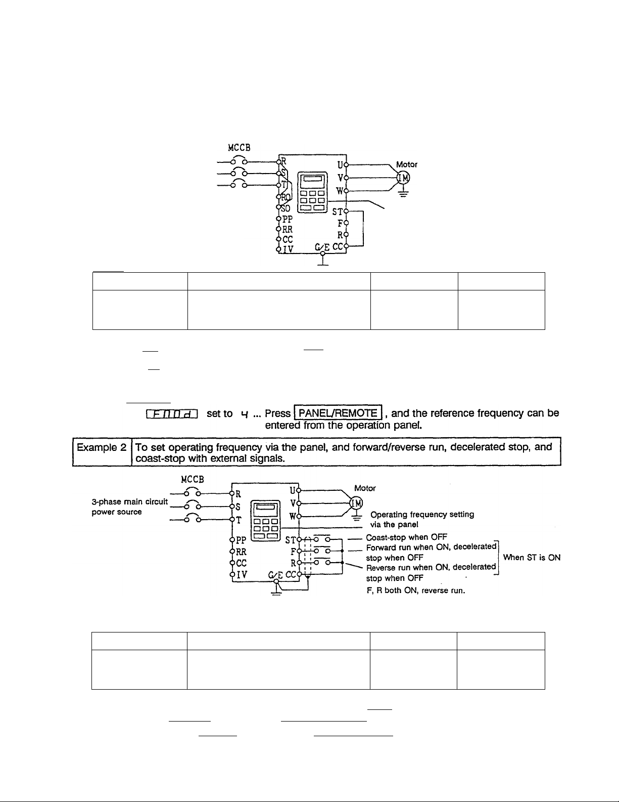
Example 1 To set run frequency, forward/reverse run, and decelerated stop via the panel.
3-phase main circuit
power source
Operating frequency setting
In standard configuration, F)0 and SO
are connected with jumpers to the main
circuit terminals. (Only for 30kW and smaller)
(Refer to page 18.)
Setting
Parameter group Parameter
Gi-.Ut
C r-.U k
C no d (Command mode selection)
F nOd (Frequency setting mode
selection)
via the panel
These are jumpered at shipment.
Setting value
Reference page
Bci H №••
2orH Notes)
40
40
Note 1)
rrwod:
rrwj'B:
set to B ... Press RUN to start running,
set to H ... Press PANEUREMOTE , then
RUN
to start running.
* Refer to page 28 '7.2 Basic Operation* for the operation methods.
Note 2) I F n n rl I set to B ... The reference frequency can be set only from the operation panel.
Setting
Parameter group
Or-.ut
0 r.U k
C nod (Command mode selection)
F nod (Frequency setting mode
Parameter
Setting value Reference page
1 OT H Not»3)
B
selection)
40
40
twice.Note 3) Emergency stop is possible from the panel by pressing STOP
I r n n H 1 set to / ... Running from operation panel is not possible.
I r n n r/1 set to M ... Press rPANELVREMOTE , and running is possible from the
operation panel by pressing RUN
15 -
Page 22
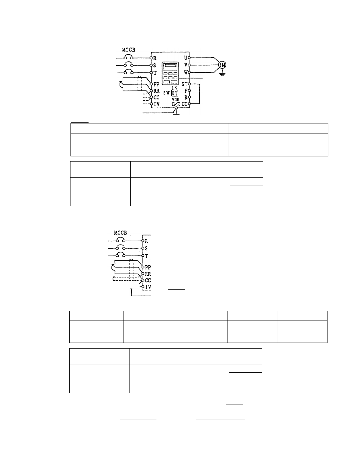
Example 3
To set operating frequency with external signals, and forward/reverse run and
decelerated stop with the panel.
__________
________
3-phase
main circuit
power source
0 Potentio
meter
@0~10Vdc
® 4~20mAdc Crirriy
0~10Vdc
Setting
Parameter group
Gr.Ub
Cr.Ut Fnod (Frequency setting mode
External operating
frequency signal
® Potentiometer
0 0~10Vdc
® 4~20mAdc
0~10Vdc
Example 4
Motor
Operating via the panel
or T
The switches are under the ROM
interface window. (Refer to page 4.)
Parameter
E no d (Command mode selection)
Setting value
1
Reference page
40
40
selection)
Cr.5F F[ 1 Setting value
Switch
SW
1
!
d
E
V side
1 side
V side
Note 5) Refer to page 69.
To set operating frequency, forward/reverse run, decelerated stop, and coast-stop via
external signals.
3-phase
main circuit
power source
0 Potentio
meter
@0~10Vdc
0 4~20mAdcCrrrrryir
I s
sw|m
VIO
G/ECC<^
Setting
Parameter group
Gr-.Uk
Er.Ub
E no d (Command mode selection)
F n Dd (Frequency setting mode
Parameter
selection)
External operating
frequency signal
Cr.5F FCI Setting value
0 Potentiometer
© 0~10Vdc
© 4~20mAdc E
0~10Vdc
STy-fA-o
FQ-i-fö”
R64-4-0
/
1
E
Motor
Coast-stop when OFF
Forward run when ON, decelerated-
stop when OFF
Reverse run when ON, decelerated
stop when OFF
F, R both ON, reverse run
Setting value
/ 0 r 4 Note 3)
/ 0 r 4 Note 4)
Switch
V side
1 side
V side
Note 5) Refer to page 69.
When
ST is ON
Reference page
40
40
Note 4) Emergency stop is possible from the panel by pressing STOP | twice.
I F n D dl set to / ... The reference frequency can only be input from the terminal block.
1 F n Dd 1 set to 4 - Press | PANELVREMOTE |, and the reference frequency can be
entered from the operation panel.
16
Page 23
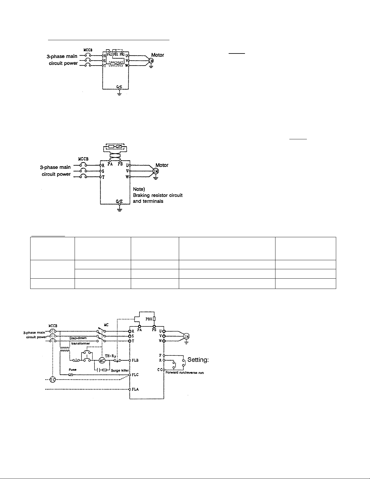
Example 5 When using built-in braking resistor
(Note) Move PR1 wiring to PB1
Example 6 When connecting a braking resistor (optional)
Note) Select a braking resistor that is higher than the min. tolerable resistance value (refer to page 95). For
22kW and larger units, the separate GTR7 (dynamic braking circuit) option is required,
a) When using an optional braking resistor with temperature fuse
Braking resistor
Setting: Set I Pbi in parameter group Cr.Pr
Setting: for 5.5kW and larger units, set I P b I in
(For 3.7kW and smaller units)
(dynamic braking selection) to 5 (dynamic
braking with overload detection).
The built-in braking resistor is connected to the
PB1 terminal (refer to page 23) at shipment.
parameter group ür.P r (dynamic braking
selection) to S (dynamic braking with overload
detection).
When using the built-in braking resistor with 3.7kW and smaller units, avoid the use of an external braking
resistor. However, parallel connection is possible in the following combinations. (For max. braking rate
applications)
Buift-in braking
resistor
200V systems 2.2kW and smaller
3.7kW
400V systems
When using an optional braking resistor without temperature fuse
b)
3.7kW and smaller 150n
70n
40n
Minimum external resistor
value that can be used with the
built-in braking resistor
70n 3sn
40n 20n
150n
TH-Ry is used as a fire prevention fail-safe.
DBR overload and overcurrent protection
functions are incorporated in the inverter
for protection of the braking resistor, but
TH-Ry operates if those protective
functions are not possible. Select TH-Ry
according to the DBR power rating.
(dynamic braking selection) to 2 (dynamic
braking with overload detection), and set the
braking resistor capacity and resistance value.
(Refer to I Pbc I | PbCP I on page 77.)
Min. total braking
resistance value
75Í1
Note) The step-down transformer does not need to be installed for 200V class inverters.
-17 -
Page 24

6.2 Terminal Functions
Table 6.2.1: Main circuit terminal functions for 3.7kW and smaller units
Main circuit terminal functions for 3.7kW and smaller units are as shown below. The internal circuit
Terminal symbol
G/E
R/L1, S/L2, T/L3
U/T1, V/T2, W/T3
PA, PB
Terminal for external grounding.
Connect to properly-rated power source.
Connect to motor (3-phase induction motor).
When built-in braking resistor is insufficient, connect to external braking
resistor (optional).
Change the settings related to dynamic braking resistor protection.
PC
Minus potential terminal for internal DC circuit
A DC power source can be input between this terminal and the PA
terminal (plus potential).
RO, SO
Control circuit power is input via the shorting bars on the terminal block
(RA-1-R0, S/L2-S0). When using a separate power supply for the control
power, remove the shorting bars before connecting the power supply.
(PR1), (PB1)
Connected to the built-in braking resistor. When not using the built-in
braking resistor, change the wiring from (PB1) to (PR1)i and then
change the settings of the dynamic braking resistor operation
parameters.
(PAD This is an internal connection, so do not remove wires from it or
connect external wires to it. It is connected to the built-in braking
resistor.
(E)
This is for internal connections, so do not remove or connect external
wires. This is wired to the inverter chassis.
Terminal function
Internal
circuit
diagram
A
A
B
Cl
Cl
D1
C1
Cl
A
Table 6.2.2: Main circuit terminal functions for 5.5kW and larger units
Main circuit terminal functions for 5.5kW and larger units are as shown below. The internal circuit
diagrams for each terminal are shown on page 21.
Terminal symbol Terminal function
diagram
G/E Terminal for external grounding.
R/L1, S/L2, T/L3 Connect to properly-rated power source.
U/T1, V/T2, W/T3
PA, PB
Connector to motor (3-phase induction motor).
Connect to the braking resistor (optional) and then set the dynamic
C2,C3,C4
braking resistor operation parameters.
PC
Minus potential terminal for internal DC main circuit.
C2,C3,C4
A DC power source can be input between this terminal and the PA
terminal (plus potentiaO.
PC, PA
Terminals for connecting a DC-link reactor (DCL) (standalone type).
C2,C3,C4
This is short circuited with a shorting bar at shipment.
RO, SO
Control circuit power is input via the shorting bars on the main circuit
terminal block (R0-R/L1, S0-S/L2). When using a separate power supply
for control power, remove the shorting bars before connecting the
power supply.
On 37kW and larger units, these terminals are not connected to the
main circuit terminals at shipment, so connect a power supply for the
control circuit.
R20, S20
Power supply output terminals (190 to 220V - 50Hz, 190 to 230V 60Hz) for operation circuits. Only installed on 400V-class 37kW and
larger units (10VA).
Internal
circuit
A
A
B
D1, D2
D2
-18-
Page 25

Table 6.2.3. Control circuit terminal functions
Control circuit terminal functions are as shown below. The internal circuit diagrams for each terminal
are shown on page 22.
Internal
Terminal symbol
Terminal function
diagram
FLA, FLB, FLC
These are the multifunction programmable relay contact outputs (refer
to page 12). The contact ratings are 250Vac-2A (COS0=1), 30Vdc-1A,
250Vac-1A (COS0=O.4).
The standard function setting detects when the inverter protection
functions have operated.
When a protection function activates, FLA-FLC will close, and FLB-FLC
will open.
P24
RCH
24Vdc power output. (Max. 100mA)
This is a multifunction programmable open-collector output (refer to
page 57). (Max. SOmAdc)
The standard function setting activates this signal when completion of
deceleration or acceleration is detected.
circuit
E
F
G
LOW This is a multifunction programmable open collector output (refer to
page 57). (Max. 50mAdc)
The standard function setting activates this signal when a low speed is
detected.
FP
This is a dedicated open-collector output. (Max. 50mAdc). Pulses that
are 48-, 96- or 360-times the output frequency are output according to
parameter settings.
The standard setting is for 48-times the output frequency.
FM This is a multifunction programmable analog output (refer to page 89.)
The standard setting is the pre-compensation reference frequency.
When connecting a meter, use a ImAdc full-scale ammeter or 7.5Vdc-
1mA full-scale voltmeter.
AM This is a multifunction programmable analog output (refer to page 89.)
The standard setting is the output current. When connecting a meter,
use a ImAdc full-scale ammeter or 7.5Vdc-1mA full-scale voltmeter.
PP This is the power supply for reference frequency setting. (lOVdc)
Connect a 3kft potentiometer (a 1 to lOkQ potentiometer may also be
used).
RR This is a multifunction programmable analog input.
The standard setting is a 0 to lOVdc input corresponding to a 0 to
80Hz frequency setting.
IV
This is a multifunction programmable analog input. Change between 0
to lOVdc (SW at V side) or 4 (0) to 20mAdc (SW at 1 side) via SW,
located under the ROM interface window. The standard setting is a 0 to
lOVdc input conresponding to a 0 to 80Hz frequency setting with the
switch at the V side.
G
H
1
1
J
K
L
RX
Tills is a multifunction programmable +!- analog input. Change
between 0 and ±lOVdc (SW at 10V side) or 0 to ±5Vdc (SW at 5V
side) via SW, located under the ROM interface window. The standard
setting is a 0 to ±10Vdc input corresponding to a 0 to 80Hz
forward/reverse frequency setting with the switch at the 10V side.
CC This is the control circuit common terminal. N
-19-
M
Page 26

Terminal symbol
ST
Terminal function
The standard setting is ‘run ready' with a short circuit between STCC. The motor will coast-stop when opened. This can also be
used for interlocks. (Run ready/ coast-stop terminal)
Internal
circuit
diagram
0
F The standard setting is forward run with a short circuit between F-
R
SI
S2
S3
S4
RES
■ 3
Q.
CC, and decelerated stop when opened. (ST-CC in ON condition)
C
*—•
0
The standard setting is reverse run with a short circuit between R-
ro
CC, and decelerated stop when opened. (ST-CC in ON condition)
c
0
The motor will reverse run when both F-CC and R-CC are short
0
CD
circuited.
JD
CO
The standard setting is preset speed run with a short circuit
e
E
between S1-CC.
CO
O)
The standard setting is preset speed run with a short circuit
0
between S2-CC.
Q.
c
0
The standard setting is preset speed run with a short circuit
0
between S3-CC.
c
3
The standard setting is preset speed run with a short circuit
D
between S4-CC.
The standard setting is that the hold during operation of the
inverter protection functions is reset with a short circuit between
RES-CC.
Even if RES-CC Is short circuited while the inverter is operating
normally, the reset function will not activate.
0
0
0
0
0
0
0
-20-
Page 27
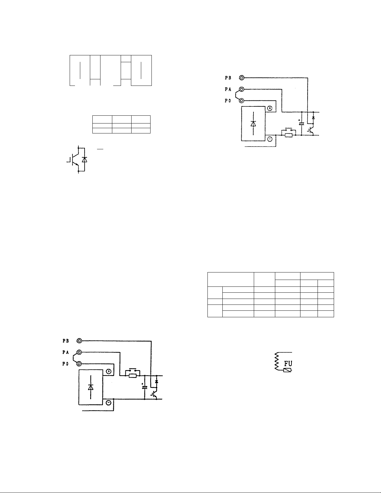
Fig. 6.2.1 Input/output internal circuits (1/2)
Sym
bol
Internal circuit diagram
E/UM
S/lit
T/l><
c/e 0“
Varistor
r
4
MOV
Lightning
L surge
Ad. A absorber
O-
SOOV «yearn •470V aooov
400V tyeam
-tV\ ■
Current detection
circuit
Bultt-in braking r-'*———•
resistor
3.7)Wand smaller
(Ptn
lO-
tfAl)
(Pin ■
"O-
HZ3
PA e-
PB O-
Capacitor
1
T
WrtearMOV
woâageiaang
■AV
‘^fuse
©
2 \
DSAnead
1000V 9000V
tA—@ W/T3
Temperature
U/Tl
V/T2
Sym
bol
Internal circuit diagram
11~18.5kW
PC (§>
22kW and larger
PB (§>—
PA J®
PO t®
PC ®-
„ RlOO
RO®
----
S 0®
-----
-------
--------
<=h-
©
-cm
0
C Bectrolytic capacitor
5.5, 7.5kW
PC ©■
tz
©
InvrtBf cepedty
‘Z/XN
7-5kWand smaller
system
aOkW and smaller
20GV 37kW and larger 60VA lOA-ISmS 33n 200|lF
7JSkWand emaJler
4CeN
system
dOtW and smaller QOVA
400V systam 37-75kW
Max. poDver
Peakinruah Component vatuea
capady
50VA
max. input
50VA
aOA-SmS
SCf^A 20A-7mS lea 220pF
2QA-3mS 320 50|iF
a0A-7mS 32Û IIOpF
RICO
16a lOOpF
c
^ 460:230 150VA
RO©
------=----
S0(§h
R20(§)-
S20©-
-21 -
Page 28
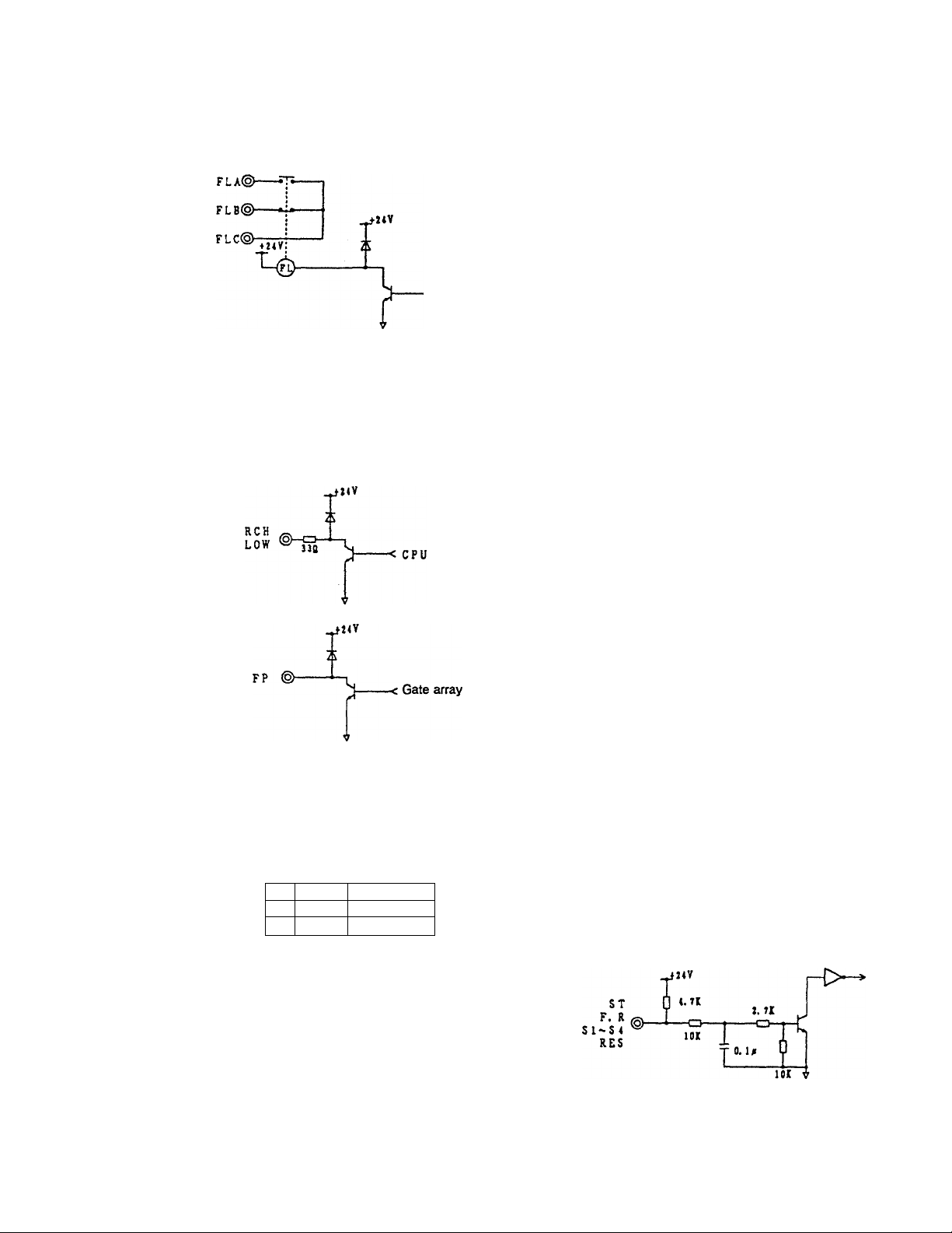
Fig. 6.2.1 Input/output internal circuits (2/2)
Sym
bol
e
©
©
Internal circuit diagram
_a»v
_ t. la T
P2 < ®
----------<z------Fuse resistor
*
< CPU
Sym
bol
©
о
internal circuit diagram
Analog input
(0~10Vdo)
18k
RR ©-
Note 1) Ф
-o-
0. 1a
CC ®------
Analog input
O-'IOVdc, 0~20mAdc)
18k
IY©b
Note 1)
-cu-
hoos
CC ©
------
Cb-IOVdo (switch at V side)
4~20mAdc (swKch at I side)
-F/-Analog input +5V
(o~+/-iovac. (K+/-5Yac)
RX <§>—
Note 1)
CC @—
------
0~6Vdc (switch at 5 side)
0—10Vdc (switch at 10 side)
Voltage converter clrcuft^ ^
Ik 33k 33k
CD- -Oj-CD—
0. iM
+ 5V
2^
A/D converter
SVmax
ll5k 2Í
+ 5V
2^
A/D converter
SVmax
5k 2i
A/D converter
2.5V±2.5V
Analog output
(D
Ф
cc ©—
4.7k
0. u
AM
PM lOOmS
PP ®-
= T
Response
3mS
Low-pass
filter
circuit
1/1024 or better
OOQ
5. lVx2
-< CPU
Resolution
1/256
©
Contact inputs
CC
@-
C/l@-
j.
Grounding
capacitor
22piF
CPU
■jü. lA
CC ©
------
1
Note 1) A capacitor is installed on the analog input terminals (RR, RX, IV), so if an output such as an
operational amplifier is directly connected to these terminals, instability may result. Always pass signals
of this type to these terminals through a lOOft to Ikfi resistor.
-22
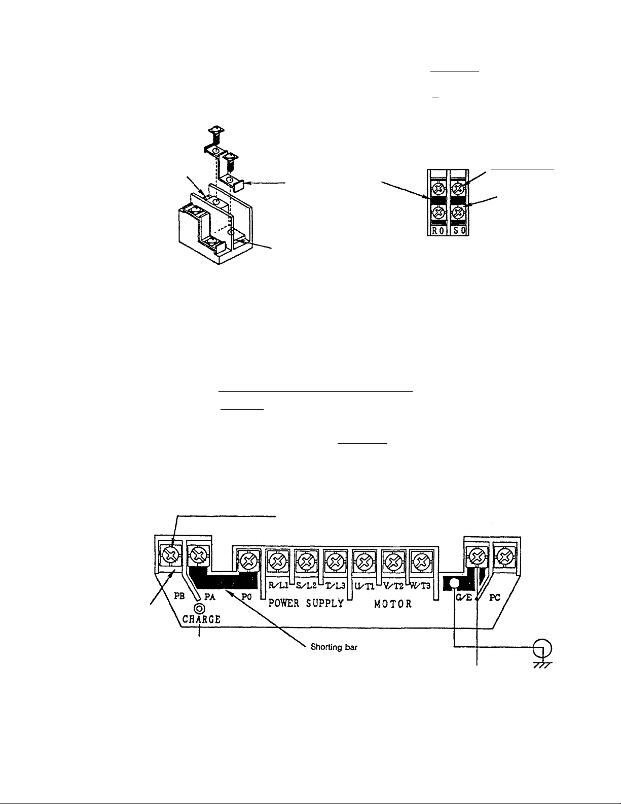
Page 29
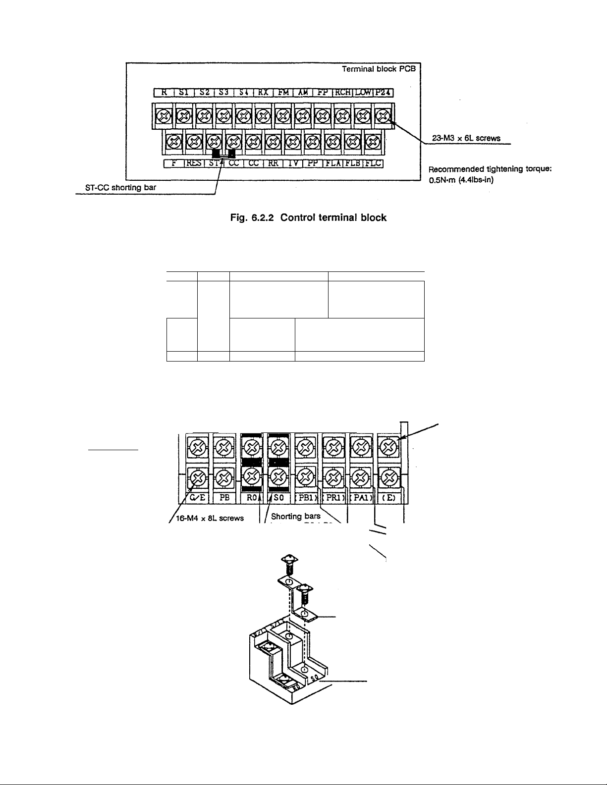
Terminal block cover
FA
R/Ll S/L2 T/L3
U/Tl V/T2 W/T3
Terminal block
CHARGE
o
Charge lamp
(Lights when there is
a charge on the main
circuit capacitors)
3.7kW and smaller units
Removal of shorting bars
Remove the two terminal screws
as shown on the right, and remove
the shorting bar
'e
©
C/E FB
©
POWER SUPPLY
EXT.
RESISTOR
PC PA R/Ll S/L2 TyL3 U/’TL V/T2 W^T3
CONTROL
R SLTPLY
RO SO
MOTOR
INTERNAL RESISTOR
ON , OFF
( PBl)
1 ( PRl) (PAD { E)
Shorting bar
With terminal cover
Recommended tightening torque:
1.2N*m (lllbs-in)
Connected to inverter chassis
Sc-v Connecte
Wired to built-in braking resistor.
When using the buiit-in braking
resistor, change the wiring from
(PR1) to (PB1).
When connecting a separate power
supply to the RO and SO terminals,
always remove the shorting bars,
or the inverter may be damaged.
Fig. 6.2.3 Main circuit terminal block (3.7kW and smaller units)
Terminal block
- 23 -
Page 30
5.5kW and larger units
Removal ot RO and SO terminal
shorting bars
Remove the two terminal screws as
shown below, and remove the
shorting bar.
RO, SO terminal block
for external wiring
Terminal block cover
Terminal block cover
^VftRNI^G]
• ttoMtan
t« Hift éfi to
tto to«rt№
ia.toetwnwL
Terminal block
Shorting bar
Connected to the main circuit
terminals. Do not connect
external wiring to the lower
terminals.
Shorting bar
CON-mOL POWER SUPPLY
200V CLASS
Note) 400V systems are indicated as ’400V CLASS“.
Fig. 6.2.4 Control power terminal block (S.SkW to 30kW units)
4-M4 X 8L screws
With terminal cover
Recommended
tightening torque;
1.2N-m (lllbsH'n)
Terminal block
With terminal cover
r
PB ^ PO ^2 ^3, ^2 % %
200V class!POWER SUPPLY MOTOR © ^
Note) 400V systems are indicated as 1400V CLASS
4-M5 X 10L screvtrs
Charge lamp
(Lights when there is
a charge on the main
circuit capacitors)
Recommended tightening torque
2.4N-m (21lbs-in)
Ground
Connected to
inverter chassis
Fig. 6.2.5 Main circuit terminal block (S.SkW to 7.5kW units)
24
Page 31

Main circuit terminal block protective covers
Main circuit terminal block
PA terminal for braking resistor
R/Ll 1 S/L2 1 T/L3
*"----POWER SUPPLY—
U/Tl 1 V/T2 1 W/T3
------
^—MOTOR
IG/E
-------
N-m
lb-«n
2.4
M5
M6 4.0
MS 8.0 71
21
35
Note) The 200V 18.5kW terminal block screw size has been changed from M6 to M8.
Fig. 6.2.6 Main circuit terminal block (IlkW to 18.5kW units)
-25-
Page 32

p (5~p
10-M8 hex. screw
Fig. 6.2.7 Main circuit terminal block (22kW to 30kW units)
,R/U S/L2 VUuUm V/T2 Wn^ PO PA PC PB
POWER SUPPLY MOTOR
DC bus P-N connections
Note) When using a braking resistor
A
with 22kW and iarger units,
the GTR7 (dynamic braking circuit)
option must be installed.
PO, PA, PC terminal block for
200V class 37kW unit
1 j
fî f
© ©
1 OÎ
(External wire connection
caution label)
PO'PA'PC external wire connections:
Install all terminals between the
washers.
Inside I'^®sher,User wiring
1 fl
©
' 1
Inverter
rating
(kW)
37
45 M10 M4
55
75
as.T,u,v.w
M10
M10
200V dass
Control power
suppf/
M4
M4
Main circuit terminal screw size
PA,PC,P0 PB
MS MS
M10 MS
MS
M10
as,T,u,v,w
Main circuit terminal block screw tightening torques
N-m Ib4ns
M4
1.2 11
M5 2.4
MS
MIO 16
M12 32
S.0
21
71
142
283
Fig.6.2.8 Main circuit terminal block (37kW to 45kW units)
400V dass
B0,S0,R20,S20 PA.PC.P0
MS M4
MS M4
MIO M4
MIO M4
-26-
PB
MS MS
MS MS
MIO
MIO
MS
MS
=p=^
G/E
MS
M5
M5
M5
Page 33

7. Operation and Adjustment
7.1 Operation Panel
The operation panel (hereafter, panel) allows the inverter to be operated, and functions and data to be set
and monitored.
LED display
Panel control LED
This LED will light when
•Panel control“ is selected.
The inverter can be operated
from the panel when this
LED is lit, and it will blink
while running.
Panel/remote key
Changes between "Panel
operation' and Terminal
block operation“.
UP key (A) and DOWN key
When a numerical value is
displayed, it can be
incremented/decremented
with these keys. When a
symbol is displayed, the next
item can be displayed by
pressing these keys.
Run key
The LED display normally indicates the operating frequency.
During status monitoring, various conditions can be monitored, and the
frequency command value can be displayed.
During parameter settings, the groups or parameter titles and setting
values can be displayed. During a fault, the cause will be displayed.
0 Lights during operating frequency setting, status monitor mode
displaying, and displaying of a group name, parameter name or
parameter setting value.
© Refer to Appendix 3, Character codes (page 123).
© Lights during option priority operation
(Refer to the Instruction Manual for the option for details.)
® ©
Units LEDs
When a numerical value is
displayed on the LED display, the
LED corresponding to the
numerical value’s units will light.
(No LEDs will be lit when A or V
units are selected.)
Monitor key
Changes between status monitor
mode and frequency display
status.
Initiates running. This key is
valid only when “Panel
control“ is selected.
Stop/reset key
This key functions as the stop key during “Panel control“. In all other
modes, emergency stop is engaged when this key is pressed twice.
During an inverter trip, the tripped state can be reset by pressing this
key twice.
(Refer to section 7.4.7 Fault reset.)
Program key
Changes between settings
monitor mode and frequency
display status.
Enter key
Selects or sets the parameter
name, data or frequency, etc.
27
Page 34

7.2 Basic Operation
Verify the following items before starting operation.
(1) Check that the wiring is correct.
(Refer to Chapter 6, Standard connections, on page 15.)
(2) Check that the power source is the correctly-rated value.
After confirming that there are no mistakes, perform simple operations with the standard settings.
Operate according to the following procedure.
When performing trial operations, run the motor at a low frequency (approx. 10Hz).
(1) Starting and stopping via the panel
Step Operation
1) Power ON
Turn ON the power source’s non-fuse breaker (MCCB).
If the LED display is OFF, all preparation conditions are not established, so
running will not be possible. Terminals ST-CC must be ‘closed*. Running is
possible when the LED display is 0.0 . Remote operation mode from the
control terminal block is automatically entered when power is turned on.
Changeover to "Panel control".
The panel control LED will light, and operation from the panel will be
possible.
(If this key is pressed again, the panel control LED will go out, and remote
operation mode from the control terminal block will once again be entered.)
Set the operating frequency.
The frequency command value can be incremented/decremented with the
UP key (A) or DOWN key (Sy). When one of these keys is pressed, the
LED display will blink, indicating that the value is being changed. When the
desired frequency is displayed, press the
frequency will be alternately displayed on the LED display.
The frequency will increase according to the acceleration time, and the motor
will rotate. The panel control LED will blink while running.
The frequency will decrease according to the deceleration time, and the
motor will decelerate and stop.
ENTER key. F C and the
3)
4)
5)
2)
A
f^ANEU
REMOTE
V
RUN
STOP
RESET
Caution
If the power switch is turned off in the 4) state, the motor will coast-stop. However, this method should
only be used in the case of an emergency.
Avoid frequent starting and stopping of the inverter by turning the power switch on and off, as this will
shorten the life of the inverter.
Page 35

(2) Changing the frequency while running
Step
1)
A
(3) Function setting and adjustment
Use the following procedure to change the "standard settings".
First, refer to the parameter list to find the parameter group where the function to be changed is, and
how the symbol name is displayed.
Blind function
In the standard setting, only groups u, F and U t can be displayed on the panel. The other
groups are blinded via the blind function in group u t ■ Unblind the desired group if necessary.
(Refer to Cr-.L/fc
r-br.U
V
ENTER
The frequency can be changed while running by pressing the UP key (A) or
DOWN key (^. Note that the frequency command value will change and
the operating frequency will chanae.
The operating frequency can be changed even if the ENTER key is not
pressed, but if the power is turned off at this time, the frequency command
value will return to the frequency set before changing.
b L n d Blind function on page 50.)
Operation
dr. U displays only those parameters for which the setting value has been changed by the user,
and the changed setting value differs from the standard default setting. [Auto edit function]
The parameter settings can also be changed in this group.
However, if a parameter setting value that is the same as the default setting is once again input, that
parameter will no longer be displayed in this group.
C i-.U sequentially compares the settings of all parameters to the standard default setting values,
so this process may take several seconds. The 0 t-.U display will blink and may not appear to
immediately react, but the C r.U search can be stopped by pressing a key other thani^,
ENTER
(There is a changed settings memo section on page 142 in which changed setting values may be
recorded.)
Panel operation mode selection
Various panel operation modes (
operations from the operation panel. If this parameter is set by mistake, the function will become valid
after a power-on initialization or fault reset is executed, and the anticipated key operations may not be
possible. In this case, reset the panel operation mode selection P h D d
(Refer to C r.U k PflOd] panel operation mode selection on page 84.)
PPDd
in 0 r.U t )can be selected to prevent undesired
or
- 29
Page 36

Parameter groups
Cr. U : User parameters
Gr.tr : Communication parameters
C r. F ; Fundamental parameters #1
C r.O / : Industrial application parameters
(V/F, accel/decel etc.) (pump)
Ctr.F E : Fundamental parameters #2 G r.O 5 : Industrial application parameters
(V/F, accel/deci etc.) (fan)
Ci-.P n : Panel control parameters
Cr.5t : Terminal selection parameters
C 5 C : Special control parameters
Qf-.5F '■ Frequency setting parameters
Or.P r- : Protection parameters
n r.P t : Pattern run parameters
Cf-.Fb : Feedback parameters
The following parameters cannot be changed while running, so stop first and then set them.
Cr-.F
Cr-.Ut
FH
uL5L
Pt
PPL
t y P
Max. frequency
Maximum voltage
frequency voltage selection
V/f pattern
Industrial application
parameters selection
Standard setting mode
selection
G r.O 3 : Industrial application parameters
(conveyor)
G r.O P ’ Industrial application parameters
(hoist)
G r.O 5 : Industrial application parameters
(textiles)
G r.O G : Industrial application parameters
(machine tools)
G r.P n : AM/FM adjustment parameters
G r. U t : Utility parameters
G r.O t : Motor parameters
Cr-.F b
Cr.nt
PCPH
nt.p
nt.t n
PG input-No. of phases
No. of motor poles
Auto-tuning
The following parameters can be changed while running, but the function will become valid only after
the motor has stopped (O.OOHz).
G r.U t
GPOd
FPOd
PPOd
oommana moae selection 0 r H t
Frequency setting mode
selection
Panel operation mode
selection
nt.c
nt.t
nt.Lj
nt.F
n t.r
Motor rated capacity
Motor type
Motor rated voltage
Motor rated frequency
Motor rated rpm
* becomes valid only after resetting.
-30-
Page 37

The method for making setting changes is explained below using maximum voltage frequency ( C <-.F ,
, L >1) as an example.
Key operation
1)
2)
A V
3)
A V
4)
PRO
ENTER
LED display
D.D
iCr.U
:Cr.u
l
'.Cr.F
:fh
l
:uL I
luL 1
1
;£D.D
Operation
Operating frequency is displayed (standard monitor mode)
The mode changes from standard monitor mode to
parameter setting mode. C i-.U , the first group name,
will be displayed.
Select the desired group name with the AV keys.
When the desired group name is displayed, press
ENTER to display the parameter names in that group.
Select the name of the parameter to be changed with the
AV keys.
When the desired parameter name is displayed, press
ENTER
ENTER to display the current parameter value.
5)
A V
6) ENTER or PRG or MON
Returns to Returns to Moves to
step 4) above, standard status
monitor
mode.
Another mode can be moved to in any of the above states by pressing the [ PRG | or | MON | keys.
However, if ENTER is not pressed first after changing a parameter setting value, the new value will not
be saved, and the original setting will be returned to when the power is turned off. Always press the
ENTER key after changing a setting.
:5D.D
luL I
^ 5 0.0
luL I
11 1
monitor
mode.
Change the parameter value with the a V keys.
When the desired parameter value is displayed, press
ENTER to save it. After the parameter name and data
are alternately displayed, the parameter name will once
again be displayed.
or I A| V
I
Returns to
step 3) above.
-31
Page 38

7.3 Operation Modes
This inverter unit has the following four operation and display modes.
MON
Standard
monitor mode
Status monitor mode
Page 35
MON ^
(Frequency setting)
Only when JO C is set
(Status alarms)
(Trip information)
PRO
Settings
monitor mode
PRO
Page 36
PRO
JOG run mo de
Page 39
PRO ^
7.3.1 Standard Monitor Mode
Standard monitor mode is automatically entered when power is turned on. The inverter’s output frequency
can be monitored and the frequency command value can be set in this mode. Status alarms are displayed
while running and trip data is displayed during an inverter trip.
(1) Frequency command value setting function.
This function can be used by pressing the
mode can be entered by pressing) MON [and settings monitor mode by pressing PRG . (Standard
monitor mode will once again be entered if the same key is pressed again.) If the frequency command
value is changed while running, the operating frequency will change according to the new value. If the
command value is ahead of the operating frequency, the motor will accelerate or decelerate according
to the acceleration/deceleration time.
This function can be locked out (changes not possible) with the frequency setting mode selection'
( I F n 0 d i in Or.Ut).
(2) Forward/reverse run changeover during run function
Forward and reverse run are possible by pressing the following keys in standard monitor mode.
Forward run
Reverse run
This changeover is valid only via panel operation, and the setting value of
also change when these key sequences are executed.
A V keys in standard monitor mode. Status monitor
Note)
the two keys simultaneously.
key +
key means to press
Fr P n will
in C r
-32
Page 39

Status alarms
(3)
Alarm characters and the frequency setting may be alternately displayed on the LED in standard
monitor mode. The following four types of characters may be displayed.
C .... When current exceeding the overcurrent stall level flows.
P .... When voltage exceeding the overvoltage stall level is generated.
L •— When 50% or more of the overload trip value is reached.
H .... When the temperature reaches the overheat protection alarm setting level.
Several alarms may also be displayed simultaneously. (’ lC’ ” PC’ ’ LPC’ )
The alarms will automatically go out when the alarm condition is removed.
(4) Trip information
The standard monitor mode trip display will be entered immediately when a trip occurs.
Display
OC ;
DCS
DCS
DC IP
DCSP
DC3P
DCL
OCR /
DCRS
DCP3
DP 1
DPS Overvoitage during deceleration
DP3
DL In
Dtnt Motor overload trip
DCr
DLr
DH Overheat trip
E
EBP 1
EEPS
ErrS
E r 3
E t~ r R
E r r 5
Er-rE
Er-rl Output current detector fault
ErrB
UC
UP 1
Oh
EF loiEFS
E t n Auto-tuning error
Et UP
n E r r
Overcurrent during acceleration
Overcurrent during deceleration
Overcurrent during constant-speed run
DC section overcurrent during acceieration
DC section overcurrent during deceleration
DC section overcurrent during constant speed run
Load-end short circuit (output terminal check) trip during start-up
U-phase short circuit
V-phase short circuit
W-phase short circuit
Overvoltage during acceleration
Overvoltage during constant-speed run
Inverter overload trip
Dynamic braking resistor overcurrent trip
Dynamic braking resistor overload trip
Emergency stop
EEPROM fault (write error)
Initial read fault
RAM fault
ROM fault
CPU error trip
Communication run command interruption error
Gate array fault
Option PCS fault trip
Low-current operating condition trip
Undervoltage trip (main circuit)
Overtorque trip
Earth-fauit trip
Inverter typeform error (Special error, refer to page 42.)
No error (Refer to past trip display on page 35.)
Explanation
The inverter status at the time of the saved trips (trips that previously occurred) can also be read.
(Refer to Status monitor mode on page 35.)
-33 -
Page 40

Trip occurrence example
(Overvoltage trip occurrence during deceleration)
Key operation Example display
DPS
MON
V
V
V
V
V
V
V
V
: 4D.0
:f r- -F
: SD.D
:c I3D
: у г e D
:p /50
, Я f r 1 1 1 f
:Ы1 IIЧ
:diiii>,
Explanation
Standard monitor mode (Trip display will blink)
The motor enters the coast-stop state.
Operating frequency at time of trip
Run direction at time of trip
Operating frequency command value at time of trip Note)
Load current (%) at time of trip
input voltage (V) at time of trip
Output voltage (V) at time of trip Note)
Input terminal status at time of trip
Input terminal status at time of trip
Output terminal status at time of trip
Note)
Note)
If there are past trips, the trip status information for a max. of four trips can be displayed in the same
manner. If
If the V
The trip tit
The trip status monitor function will remain active until power is turned OFF or the trip is cleared.
Note) The display will follow nOn I to fl On H in C r.U t.
The fault trip hold function will not maintain fault status after power is turned off, after a reset, or if a
fault occurs during CPU initialization. Instead, the current monitor item will be displayed.
MON
key is held down during the above steps, the display will change to the next item every 0.5 sec.
e display state can be changed to if the MON key is pressed at any time.
Other monitor items can be displayed by changing the settings of | n O n I | to n 0 n H before
clearing the trip.
is pressed, the initial display will be returned to.
34
Page 41

7.3.2 Status Monitor Mode
This function monitors the various status items (frequency setting, output voltage, current, terminal
information, etc.). This mode can be entered by pressing the MON key in standard monitor mode. To
exit this mode, press the PRG key to move to settings monitor mode, or MON to return to standard
monitor mode.
Example of monitor operation in standard monitor mode.
(Assume that the motor is running.)
Key operation
MON
Л
V
Л V
Л V
Л V
Л V
Л V
Л
V
Л V
Example display
6 0.D
; F 1— F
: Б0.0
:c 100
:угоо
:p3DD
:r, ,,,ii
:ы1чП
lOxllll
:ьп.п 1
Explanation
Standard monitor mode (operating frequency is displayed)
Run direction (Forward run f . reverse run r ) Note 1)
Operating frequency command value Note 2) Поп I
Load current (%/A) monitor Note 2) Поп5
Input voltage (V/%) monitor Notes 2) and 3) flan]
Output voltage (V/%) monitor Notes 2) and 4) | nonH
Input terminal status monitor
Input terminal status monitor
Output terminal status monitor
Cumulative run time Note 5)
in Cr.Ufc
Л V
Л V
Л
V
Л
V
Л
V
:осэ ^ 1
:0H ^3
:dp3 ^3
n E г г < > Ч
:Fr -F
(Alternating display) past trip 1
(Alternating display) past trip 2
(Alternating display) past trip 3
(Alternating display) past trip 4
Run direction (Monitor top menu item)
-35
Page 42

Note 1) When \ d / 5 <- ] in C <-.F (reverse run disable selection) is set to / , the display will always be:
: F r- - F •
Note 2) Four monitor elements can be selected by the status monitor display selections in C c. U t •
In addition, the display units for current and voltage elements can be set to A, V (respectively) or
%.
Note 3) The input voltage value displayed is calculated by multiplying 1/\^ times the DC voltage obtained
by rectifying the input voltage. If the input voltage drops below 10OV, the display will be;
;y
----------
Note 4) The display will be:: P
Note 5) The cumulative run time is counted only while running.
(The time is not counted when the output frequency monitor is displaying D. D.)
The value shown is in 100-hour units ( D.D / ~ 3 9 9 : 1 hour to 99900 hours)
When the
every 0.5 sec.
terminal input operation mode can be switched to (only when stopped) at any point in the process. The
sec.
7.3.3 Settings Monitor Mode
.
----------------
A
V
symbol in the example indicates that the left and right symbols are alternately displayed every 0.5
keys are held down during the above steps, the display will change to the next item
The run/stop, frequency display status or settings monitor mode can be entered, and
when only control power is applied.
This mode is entered by pressing the PRG key in standard monitor mode.
To exit this mode, press the PRG key to move to standard monitor mode, or the
to status monitor mode.
As described below, this mode both displays parameters and settings, and contains the setting and
adjustment functions.
The "Panel Operation Mode Selection" ( P 0 Q d in C r.U h) must be set to 3 9 or greater in order to
change parameter settings. (The standard default setting allows this.)
The "Panel Operation Mode Selection" parameter can be changed even when set to "parameter changes
prohibited".
(1) Parameter setting and display function
Use the following procedure to set the desired parameter value.
1. Press
2. At the group title display, press
display the group’s parameter names.
3. At the parameter name display, press
ENTER to display the data setting.
4. At the data setting display, change the data with the
5. Save the changed data by pressing ENTER
PRG
to enter settings monitor mode.
A V
to select the desired group, then press
A V
to select the parameter name, then press
keys.
V
A
MON key to move
ENTER
to
-36-
Page 43

(2) Settings monitor mode adjustment function (Parameter group C r.Rfl )
This function is used to adjust the scale when an analog meter is installed to monitor the output
frequency or current.
This adjustment is done in the same manner as the parameter setting and display function, except that
the meter indicator amplitude changes, instead of the LED display, when the
A V
pressed. The value indicated by the meter is adjusted to match the LED display, and is adjusted while
running.
If C r-.R n is not displayed, set b L n d (blind function) in G r.U t. (Refer to page 50.)
Example of FM (Frequency Meter) adjustment
keys are
Key operation
PRC
A V
ENTE n
\/
A
V
z_\
Ft
ENTE
V
A
R
ENTE
V
Example display
SD.0
:Cr.u
iCr.nn
iCr.Rn
-* :fr5l
:fr5l
FR5L
: a
:frsl
0
:fr
: 6 0.0
Explanation
Standard monitor mode (operating frequency is displayed)
Change to settings monitor mode.
Select 0 r-.R n . (The group name will change when AV are
pressed.) UiiiF :HF S —-— O t t
Set the group. The first parameter name will be displayed.
Select the parameter name. (The parameter name will change
when A V are pressed.) F 0 5 L R:^ R5L AiR 0
Set the parameter. The parameter setting will be displayed.
Select the FM terminal function with theA V keys to output the
pre-compensation reference frequency.
Set the data
Display the next parameter name.
Set the parameter. The FM adjustment mode will be entered.
(The adjustment value will be displayed.)
A
V
: 6 0.0
Adjust the frequency meter value with the A V keys. (The
display will blink)
1
I
1
i
ENTE R
PRG
G 0.0
6 0.0
Note) When DC voltage is selected for | F 0 5 L
OFF ( n D F F status), the FM (AM) output will not be 0, but instead will show a slight output.
- (Adjust with the ^ V keys until the LED display and meter
The adjustment value will be stored in inverter memory. (The
blinking will stop.)
Move to standard monitor mode (frequency display).
- (The LED display will not change, but the meter indicator
wiil move.)
value are the same.)
or
R n 5 L and the main circuit power is turned
-37
Page 44

(3) Setting value alarm display
When a setting value and one of the following alarms are alternately displayed on the LED, a setting
value limitation is indicated.
H I alarm (upper limit alarm)... When the upperlimit ofthe setting range has been reached, orwhen
the setting value of the current parameter being changed exceeds
its upper limit value as a result of another parameter setting value
being changed. (In the latter case, the value will be corrected to its
upper limit value.)
L 0 alarm (lower limit alarm) ... When the lower limit ofthe setting range has been reached, or when
the setting value of the current parameter being changed exceeds
its lower limit value as a result of another parameter setting value
being changed. (In the latter case, the value will be corrected to its
lower limit value.)
The data settings of parameters that have an adjustment range limited by the setting values of |l L
and ju l| , such as the preset speed frequency parameters, cannot exceed the values of FT] and
UL
When the F H
UL
or
L L
parameter values are changed, the setting values of some
parameters may exceed their limits as a result. In this case, an alarm will be displayed when a
parameter with a setting exceeding its adjustment range is selected and adjustment is attempted. To
change a parameter with this type of setting value, the moment that the
keys are pressed.
V
the alarm will be displayed and the setting value will change to its limiting value.
If F lI is exceeded, the value will become the same value as
L L
If
is exceeded, the value will become the same value as
UL
L L
Example when |L/ L
Key operation
PRC
/
V
R
ENTE
7
Д
CrrtK
Л
V
LED display
:Пг-.и
iCr.SF
;fc /
:5r0 1
: B0.0
: saa
— H /
: 5 3.9
“Decreasing"
: 4 0.0
; 4 00
— L 0
60Hz, ]l L| = 40Hz, and
Select C 5 F .
Select 5 r 0 1 .
(Upper limit alarm) The value becomes the U L value. (Same as
when the V key is pressed.)
Hold down the V key.
L L is reached (lower limit frequency)
The alarm information will be alternately displayed as long as the
V key is pressed.
5 r~ D I ~ 80Hz is set.
Operation
- 38
Page 45

7.3.4 JOG Run Mode
This mode is used to run the inverter at low speeds, and especially allows short-time runs (inching) to be
done easily. The following explanation is for executing jog from the panel. When using terminal block
signals to execute jog, refer to the parameter explanation section for C . 5 F JOG
This mode is entered via the following procedure.
The JOG run frequency (| J 0 G |in G r-.S F) and JOG stop control ( J 5 t P in G r-.S F)
parameters must be set from settings monitor mode before entering this mode. (Refer to page 70.)
Key operation Example display
PRG
PRG
V
RUN
PRG
Cr.U
:f JDG
JDG
5.0
0.0
Explanation
Press the
if a different key sequence is pressed.
The JOG mode will be entered when the
PRG key twice. The JOG mode will not be entered
____________
PRG
key is pressed
the second time only if panel control mode is selected and the
JOG run frequency setting value is not OHz. (Forward JOG)
If panel control mode is not selected or the JOG run frequency
is not set, operation will return to standard monitor mode
(frequency display) when the
PRG key is pressed the second
time.
Execute reverse JOG by pressing V •
Execute forward JOG by pressing A •
The JOG run frequency will continue to be output while the
RUN key is held down.
Standard monitor mode will be returned to when PRG is
pressed.
Note) If positioning is attempted in JOG run mode and the motor shaft does not smoothly stop at the
desired location, set the output short-circuit detection selection (
OCL 5 in Or.Pr )setting
value to 0 (position sensing during JOG). (Refer to page 80.)
-39
Page 46

7.4 Operation Mode Selection
The methods for operation and adjustment from the operation panei, validating/invalidating operating
commands from the terminal block, selection of the stopping method, and resetting are explained in this
section.
7.4.1 Operation Mode Changeover
Panel operation mode or terminal block operation mode can be selected.
• When terminal block operation mode (REMOTE) is selected, commands from the panel are ignored.
• When panel operation mode (PANEL) is selected, commands from the terminal block are ignored.
The operation mode is changed by the PANEL/REMOTE key, and can be done only when the motor is
stopped. (When stopped, OFF or a frequency display of D.0 will be shown.)
Terminal operation mode is automatically entered after power is turned on, unless the input mode is preset
as explained below. The panel control LED will be lit when panel operation is selected.
7.4.2 Run/stop Command [ j C nOd I in Ci-.ut ]
The following sources can be selected for run/stop commands (command mode).
C n o d setting Function
0
1
2
a
H
7.4.3 Frequency Command Source Setting Function [ I F flDd 1 in Dr.ut ]
This function allows the selection of the frequency command source as follows, according to the frequency
setting mode selection parameter (I F ilD dl in 0 r.ut ).
F no d setting
0
1
S
3
H
Only RS232C input valid
Terminal block input valid Note)
Panel input valid
Communication option board input
valid
All valid
Function
Only RS232C input valid
Terminal block input valid
Panel input valid
Communication option board input
valid
All valid
Note) The intended input functions are
G r. 5 fc ; input(fc * in
terminal function setting values 0 to 5,
8 and 9, on page 55.
(Refer to pages 55 and 86 for details.)
-40
Page 47

7.4.4 Parameter Setting Function f I P /7 0 d I in Cn.Ut I
Parameters can be set in the standard mode, but alternatively, the panel operation mode selection
(I Pn Od I in C r-.U fc ) can be changed as follows.
PnOdsetting
0
+ 1
+ 2
+ H
+ B
+ IE
+ 33 Can perform parameter change operations
E3
* If I P n 0 d\ is set to 3 , I (reset operations) and 3 (monitor operations) will be valid.
Prohibit all key operations
Can perform reset
Can perform monitor operations
Can perform emergency stop
Can perform run/stop operations
Can perform parameter read operations
Standard mode (all operations valid)
Function
41
Page 48

7.4.5 Standard Parameter Value Reset Function [ | fc H P | in Ci-.Ub ]
All parameter values can be changed to standard settings at one time by setting parameter | fc HP
The operation is performed as described below, but cannot be done while the inverter is running. Stop the
inverter before performing this operation.
Key operation
1)
PRO
2)
Л V
3)
4)
Л
Л V
V
Example display
0.0
iCr.U
:Gr.u
1
iGr.Ut
:rpl
ir
:t yp
i
:o 0
:d
In /fc
Explanation
Frequency display (stopped condition)
Enter parameter setting mode from standard monitor mode.
G r.U will be displayed.
Select G r.U t with the AV keys.
г —— Ut^ntTlu:
When G/-.Ut is displayed, press the ENTER key. The first
parameter name will be displayed.
Select fc У P with the Д V keys.
When fc У P is displayed, press the ENTER key,
Change the setting with the AV keys.
I : Standard setting for 50Hz applications. (See Fig. 7.5)
P : Standard setting for 60Hz applications. (See Fig. 7.5)
3 : Return to factory settings (Fig. 7.5) Note 2)
H : Trip clear
5 : Save user-set parameters
S : TYP 5 reset
q : Initialize inverter typeform Note 3)
When the desired data is displayed, press the | ENTER | key.
In It will be displayed, and operation will return to standard
monitor mode.
Notice
When [Fy^ = / is selected, only the max, frequency (p h| , maximum voltage frequency
T1
FCHG
F - PR
________ will change to S 0 . No other data will be changed.
2. When fc y P = p is selected, only the above parameters will change to E 0 •
3. Setting fc y P is not possible while running. Stop the inverter and then change the setting.
Note 1) A dual display of the previous setting value and current setting value (always 0) is used.
) p| , upper limit frequency I u fcl . commercial power/inverter switching frequency
, and frequency setting signals ¡F - P s\ , jp - P ч| , |p - P Б
0
Previous setting Current setting
-42-
' ' ' ■ jp _ pg| ^and
Page 49

O H z 5 0 H z
Output frequency
Fig. 7.5 Standard Setting Value
6 0 H z
O H z
6 0 H z 8 0 H z
Output frequency
Note 2) When
to factory settings.
Note 3)
7.4.6 Selection of Stopping Method from the Panel
STOP/RESET key, the following stopping methods can be used from the panel.
Stopping method
Coast-stop
Emergency stop
(To forcibly stop
with the panel when
not in panel run
mode.)
t yp
installed in a different inverter unit, and to reset the typeform to that of the new inverter.
Verify that the inverter typeform contained in the table on page 124 matches the
value of
In addition to the normal decelerated stop (deceleration according to the set deceleration time) with the
fc y P
F Or n in C n.Ut , and then execute the fc y P function.
The power output to
the motor from the
inverter is shut off,
so the motor will
coast and then
stop.
Select from the
following:
• Coast-stop
• Decelerated stop
• Emergency DC
(note)
The default setting
of |E 5 fc P| in
coast-stop.
= 3 is selected, all parameters other than those in
= 1 is used to clear an E t y P error that may occur when a control PCS is
Operation
injection braking
stop
C r.P r-
IS
Ci-.Rn will return
Method and setting
This is possible only when operation from the panel is
valid.
1. Press PANEI7REMOTE during panel run.
2.
Standard monitor mode will be entered, and the LED
will display C t r L ■
3.
Coast-stop will be activated by pressing
STOP/RESET . (If another key is pressed, the
CtrL display will go out and the process will be
canceled. The process will also be canceled if the key
is not pressed within 3 seconds.)
Assume that terminal block run mode is active. (Normal
stopping is possible when in panel mode.)
1.
Press the STOP/RESET key.
2.
Standard monitor mode will be entered, and the LED
will display E 0 F F .
3.
Press STOP/RESET
4.
The LED will display E
according to the setting of
a i~.p r~
This mode will be canceled if a key other than
STOP/RESET is pressed when E d F F is
displayed.
again.
and the motor will stop
ESfc P
in
-43 -
Page 50

(Note)
ESfcP in Cr.Pf- settings: D
Coast-stop
Decelerated stop
I
Emergency DC injection braking stop
If E is selected, also set the DC injection current
db C and ESTOP DC injection time E dbt
* If DC braking is not required during normal stopping when
braking stop) is selected, set the DC braking time jcf b fc
ESfcP = E (emergency DC injection
to О .
Caution
The emergency stop command forcibly stops the motor with the inverter unit key operation even if the
command mode is not set to panel operation mode. This command cannot be prohibited with the
command mode selection. When executed, the emergency stop will be regarded as a trip and will be
recorded as a past fault.
7.4.7 Fault Reset
Remove the trip cause before resetting an inverter that has tripped due to a failure or other fault. The
inverter will trip again if the cause is not removed.
Reset the tripped state with one of the following methods:
Reset
(1) Turn off the power (until the LED display goes out) Note 1)
(2) External signal (short circuit between control terminals RES-CC)
(3) Panel operation
Note 1)
Refer to
________
Cr-.Pr-
t г CL I (page 80).
Resetting with the panel is performed by the following process.
1. Press
STOP/RESET and confirm that CL г is displayed.
2. Press STOP/RESET again, and if the trip cause has been removed, the inverter will be reset.
* For the following overload trips, the inverter cannot be reset with an external signal or with the panel
during the required cooling time.
DL In
DLPb
DL
: inverter overload
: motor overload
: dynamic braking resistor overload
The standard cooling time settings are as follow:
DL In
DL Dfc
DL
: Approx. 1 minute after trip
: Approx. 5 minutes after trip
: Approx. 30 seconds after trip
Caution
To reset immediately due to an emergency, the power can be turned off to reset the inverter, but if
this method is used frequently, the inverter or motor may be damaged.
- 44
Page 51

8. Parameter Explanations
r- ^
LJ f~ ,
U
I (Fundamental Parameters #1)
L I
U
L5L
V/f settings
U
L U I
Related parameters
FH
uL 1
The V/f settings are among the most important parameters. The motor voltage to frequency ratio is set by them.
uL SL set to 0
Output
Maximum frequency
Maximum voltage frequency
(Output voltage and frequency ratio setting)
LJ L 5 L
uLu /
Li L S L set to /, 3
Output
Maximum voltage frequency voltage selection
Maximum voltage
Set to D : Vj, fluctuates according
to the input voltage
* Even if I i-»L u /1 is set higher than the input voltage, the output voltage will not be higher than the input
voltage.
* Even if I uL u 11 is set when | wL 5L is set to /, it will be ignored
Set to I : Vq is automatically set between the following values
according to the input voltage when the power is
turned on.
200V class; 200 to 230Vac
400V class: 380 to 460Vac
Set to 3 : Vo is set with
45 -
/
Page 52

r~ , F~ (Fundamental Parameters #1)
Pb
Related parameters
Pt
,b I
,L I
Constant torque, variable torque, automatic torque boost, automatic energy saving, and vector control can be
selected for the V/f pattern.
Pfcsetto I Constant torque
V/f pattern
Voltage boost
Maximum voltage frequency
characteristics
V/f pattern ©
Cr-. nt nt.P
nt£
nt.t
nt.L
nt.P
nt.r
Pfrsetto P Variable torque
No. of motor poles
Motor rated capacity
Motor type
Motor rated voltage
Motor rated frequency
Motor rated RPM
characteristics
* If the voltage boost value is set too high, the motor will be overexcited, and an OL or OC trip may occur. In
some cases, this may also shorten the life of the inverter.
* The voltage boost value is automatically initially set for the max. applicable motor according to the inverter
capacity. If a standard motor matching the inverter capacity is used, the value does not necessarily need to
be adjusted. Even when readjusting, setting to within ±2% of the initial setting value is recommended.
P E set to 3 Automatic torque boost
The load current is detected, and the inverter’s
output voltage (torque) is automatically
adjusted.
Pfc I and [ Hfc.P I cannot be changed while running. Even if I Hfc.C I , I Hfc.fc | , I nt.u I, I nt.P
ITE^ are changed while running, the changes will not become valid until the motor is stopped
(O.OOHz).
P fc set to 4
P fc set to 5
_____________
P fc set to 6 I Vector control with automatic energy saving
Automatic torque boost with
automatic energy saving
Vector control
Motor speed fluctuations are suppressed,
even with high torque at low frequencies.
The output voltage is closely monitored during
the automatic torque boost (vector control)
setting, and energy is saved by allowing only
the proper amount of current to flow that is
suitable for that output voltage.
-46 -
Page 53

F
(Fundamental Parameters #1)
Pt
Parameter setting process when | Pt I is set to 3
Cn.F
CpF]
v/f pattern
1: V/f control (using constant torque load)
2: V/f control
(using variable torque load)
3: Automatic torque boost
4: Automatic torque boost +
energy saving
5: Vector control
6: Vector control +
energy saving
Motor requirements when using vector control
1. Motor capacity should be the same as the inverter, or should be a Toshiba general purpose squirrel-
cage type motor or Toshiba constant torque motor that differs by at most 1 rank.
2. No. of motor poles should be 2 to 16.
3. Only one machine should be operated (one motor per inverter).
* The output frequency and set frequency will not match.
* The max. wire length that can be used between the inverter and motor is 30m. If 30m is exceeded, the
torque can be improved during deceleration by using auto-tuning, but the torque will drop slightly near
60Hz.
V/f pattern ®
r^Gr.nt
When 3-5
are selected
ntp
nt£
nt.t
nt. IH
c r.n t
nt.u
nt.F
nt.r-
nt.t n
No. of motor poles
Motor rated capacity
Motor type
0: Toshiba standard motor
1: Toshiba VF motor
2: Other
Load moment of inertia
0: Small
1: Medium
3; Very large
Motor rated voltage
Motor rated frequency
Motor rated RPM
Auto-tuning
0: disabled
1: enabled
-----------------------------
-
The vector control function will operate properly with adequate torque and little speed fluctuation when
used below the maximum voltage frequency setting value. However, in situations where the maximum
voltage frequency is exceeded (field-weakening area), the same type of characteristics may not be
achieved. The maximum voltage frequency setting range during vector control use should be between 40
to 120Hz.
The motor rated voltage parameter i nt.u I is used only to calculate motor constants. The inverter’s max.
output voltage will always depend on the maximum voltage I uL lj f I during vector control.
Cautions during auto-tuning
(T) The motor must be completely stopped before executing auto-tuning. Due to motor residual voltage,
an error may occur in the tuning if executed immediately after stopping.
0 The motor will rotate only slightly during auto-tuning, but use caution, as the main voltage will be
applied.
0 Auto-tuning will normally finish within 3 sec. If an error occurs, the inverter will trip and the motor
constants will not be set.
0 Auto-tuning of special motors, such as high-speed or high-slip motors, is not possible.
★ The auto-tuming error (refer to page 121) will be displayed when auto-tuning fails.
* Change the t nfc. /H I setting value if an overvoltage trip ( 0 P) or overcurrent trip (DC ), etc., occur. Then
retry the auto-tuning operation.
47 -
Page 54

Or. F
(Fundamental Parameters #1)
О Г 1
ri L L- 1
ЯСС 1
dEC 1
• The acceleration time ЯСС is the time to reach the max. frequency
deceleration time dEC is the time to reach OHz from the max. frequency
The setting adjustment range and resolution can be set by the Acc/Dec time units selection | dSPt ,
Output frequency
Deceleration time #1
dE-L I
Acceleration time #1 Cr. F3
Acceleration/deceleration time settings
ЯССЗ
dECE
Cr. Ut dSPb
Acceleration time #2
Deceleration time #2
Acc/Dec time units selection
FH from OHz, and the
FH .
* The default acceleration/deceleration time settings will depend on the inverter capacity.
* Switching between | ЯСС I [ | dEC 11 and | ЯССЕ | | d£CE | is possible with the operating
panel or terminal block. Switching can also take place at a set frequency.
(Refer to acceleration/deceleration #1 and #2 selection on page 52.)
Page 55

ür. F
(Fundamental Parameters #1)
rs C Lj
5LL
Related parameters
SCu 1
SCL
An acc/dec pattern that matches the application can be selected.
SCu I set to 0 (Linear acc/dec) This is a general acceleration/deceleration pattern, and is used under
SCu I set to I (Self-adjusting function) An acceleration/deceleration time that matches the load conditions
Self-adjusting function
This function cannot be used when the frequency reference constantly fluctuates or when the load
changes suddenly. The |ncc j jdEC | parameters will be automatically changed, but when the control
power is turned OFF, the settings will return to their original values.
To save the self-adjusting function results, display jflCC ] ^
the data setting blink by pressing the
write the data
Set C/-.F?
Acc/Dec pattern #1
Acc/Dec pattern adjustment
- Acc/Dec patterns,
5 E H~ ■
Acc/Dec pattern adjustment, Low/High
SCH
most circumstances.
is automatically set.
or
A
V
SCuS I for^ andpECE.
Acc/Dec pattern adjustment (HIGH)
in 0 r.U , press ENTER , make
keys once, and then press
ENTER
SCu I set to 3 (S-Pattern #1)
SCu I set to 3 (S-Pattern #2)
Examples of acceleration/deceleration pattern settings
SCu / set to 3
(Adjusted with
Output
frequency
5CL and 5CH )
This pattern is used when accelerating/decelerating to a high speed
area (exceeding 60Hz) is required in a short time. This pattern is
suitable for conveyers, etc.
This pattern gradually accelerates in the field-weakening area where
the motor’s acceleration torque is small. This pattern is suitable
for high-speed spindles.
SCu 1 set to 3
(Adjusted with maximum voltage frequency)
Output
Note that actual acceleration/deceleration times of the S-pattern will be longer than the linear times by the values
of *1 and *2.
The curve will depend on the (max. voltage frequency/max. frequency), and the inclination will taper off as the
(max. voltage frequency/max frequency) decrease, and the actual acceleration time will increase. (The rate of
acceleration will decrease in the field-weakening area.)
-49-
Page 56

u r,LJ b
(Utility Parameters)
b L n d Blind function selection
Related parameters
bLnd Blind function selection
It is possible to not display the parameter groups other than C r.F . Ut and U when they are not necessary.
bL Fg I ~ I bL /lb Group blind selections
bind setting value
0
/
★ The parameters bL F g | ~ bL Ob will be displayed when bLnd is set to I . Cancel the blind
function for the desired parameter group by setting its corresponding parameter value to / ( | b L F g | for
Cr.Fg ).
Example) To cancel the blind function for parameter group Cr.Rn
Key
operation
1)
2)
A
ENTER
3)
A
ENTER
PRG
V
V
Display Explanation
D.D
; Cr-.U
: Cr-.U
: C f-.U b
; RPL
i
: bLnd
1
: 0
Blind
Selective unblinding
i
Function
Frequency display (stopped condition)
Enter the parameter setting mode from standard monitor mode. The name
of the first group ( C t-.U ) will be displayed.
Select the group with the AV keys.
Display C I-.U b , and press ENTER .
Select the parameter with the AV keys.
Display 1 b L n g 1 . and press ENTER .
4)
5)
6)
V
A
ENTER
V
A
ENTER
V
A
ENTER
; /
'■ b L n d
<
----
> 1
'■bLnd
■ bL n d
i
: bLRR
4
: 0
: 1
; bLRR
<-■ > /
: bLRR
Change the data with the AV keys.
Cancel the blind function. (Set to ; )
Press ENTER .
The parameter name and data will be alternately displayed, and then the
parameter name will be displayed .
Parameters b L + the group name will appear after the 1 bL ng 1
parameter. Select the group which is to be unblinded.
Display the group to be unblinded, and then press ENTER .
Change the data with the AV keys.
Unblind the group. (Set to i)
The parameter name and data will be alternately displayed, and then the
parameter name will be displayed.
Page 57

и г.
F
(Fundamental Parameters #1)
( Г I
и L-
Related parameters
UL
The upper limit frequency UL sets the upper limit of the output frequency, and the lower limit frequency
L l ' I sets the lower limit of the output frequency.
The upper limit frequency can be set between 0 and the max. frequency.
The lower limit frequency can be set between 0 and the upper limit frequency.
Upper limit frequency
Output frequency H z
Upper limit/lower limit frequencies
LL
Lower limit frequency
Output frequency Hz
0
Frequency setting signal
* A frequency exceeding
U L will not be output.
* The operating frequency can only be set within the range of the upper limit frequency and lower limit
frequency when set from the panel. An error display ( H I S 0.0 alternately displayed) will occur if
an attempt is made to set the frequency from the panel above 50Hz when the upper limit frequency is set to
50Hz.
* The output frequency cannot
be set below l L
d I S г Reverse operation disable selection
This is used to prevent reverse run problems which may occur if an incorrect start signal is input.
d 15 г setting value
0
1
* This applies to both panel and external control.
Reverse operation allowed
Reverse operation not allowed
Function
- 51
Page 58

[j f- , P n (Panel Control Parameters)
P cd P Acc/dec #1 and #2 selection
Related parameters
Rd3 Acc/dec #1 and #2 selection
Automatic switching of the acc/dec times can be easily performed by combining the use of terminal block input
AD2, acc/dec #1 and #2 selection Rd3 > and acc/dec #1 and #2 switching frequency Rd3F
(Refer to CROd in Cr. Lit and it* in Hr. St {*: 0 to /0) for setting the terminal
block inputs.)
C r.F 3 Rd3F Acc/dec #1 and #2 switching frequency
Time [S]
—>
* Refer to the section on command mode selection ( CROd in Cr. Ub ) for the selection of the
start/stop command.
* If the start/stop command source is selected to be the operating panel, the acc/dec will function according
to the setting of parameter Rd3 regardless of the state of terminals AD2-CC.
* If the start/stop command source is selected to be the input terminals, acceleration/deceleration #1
and #2 switching will be selected by the terminal input AD2-CC state regardless of the setting of parameter
Rd3 .
52 -
Page 59

u r
P j (Panel Control Parameters)
r
PFb
This is used when Gr. F b feedback parameters are used.
* If no feedback control is selected with the C»~. Fb feedback control selection parameter j F bP I
feedback control will not occur even if panel feedback control ON ( PFbC = D) is selected.
★ Refer to the section on C r. F b for feedback control.
PrE5
The trip causes that can be reset when the inverter trips as a result of a failure or fault, etc., can be selected.
P r E 5 setting value
D
1
3
Panel feedback control
Panel reset selection
Function
All possible
Only OL can be reset
Only OL, 001, 0C2, and 0C3 can be reset
★ The trip cause must be removed before the inverter is reset, or the inverter will trip again.
OL indicates DL - in , DL - lib , and OLr . Resetting is not possible during the required cooling
time after tripping. The inverter can be reset, however, by turning the control power OFF.
Required cooling time under standard settings DL - In : Approx. 1 min.
DL - fib : Approx. 5 min.
DL r : Approx. 30 sec.
53 -
Page 60

r ^
u r •
n (Panel Control Parameters)
P b P R d E
Related parameters
PbP Fundamental parameter
switching
This parameter is used when two different types of motors are used by one inverter or when the motor V/F
characteristics are to be changed while running.
C«-.F
(Fundamental parameters #1)
Gr.Pr
(Protection parameters)
RCC I
dED I
5Cu I
u L 1 Maximum voltaae frequency
ju L u/ f Maximum voltage
u b 1 Voltage boost
t Hr l| Sectronic thermal protection level
5tE /] Stall protection
5tL 1 Stall protection level
Acceleration time
Deceleration time
Acc/Dec pattern
Dr. FS
(Fundamental
parameters
#2)
RCEE
dEES
Ed]
uLS
uL uS
ubS
tHrP
5tLE
Fundamental parameter switching
RdP
IbO
Switching from
Switch with
/ : Acc/dec #1
5 : Acc/dec #2
Switch with \PtP
I: Fundamental
parameters #1
(V/F#1)
2: Fundamental
parameters #2
(V/F#2)
Acc/dec #1 and #2 selection
~ It ID I Input terminal selections
Switching from
the panel
the terminal block
Switch with input terminal
function I ft *| setto
9 (AD2 switching
selection)
Switch with input terminal
function I f fc: set to
¡P (fundamental
parameter switching)
- 54 -
**: select / to /0 according to the terminal
being used. (Refer to j f fc inC r.51)
Page 61

u r
5 Izi Selection Parameters)
It
Input terminal selections ©
to It ID
Related parameters
It
ItD
It I I
Parameter
Input terminal
The input terminal functions can be changed by setting
in the following table.
Note 1) Input terminals S5, S6 and S7 are added with the expansion terminal block PCS (optional).
Note 2) If the same setting value is assigned to more than 1 input terminal function, *OR’ logic is in effect.
Note 3) To turn each terminal ON/OFF, open/close each terminal-CC (closed=ON, open=OFF).
Setting
value
D
1
5
B
H
5
B
n
B
9
10
1 1
IB
13
19
IS
IE
in
IB
19
BO
B 1
BB
B3
BH
B5
IkO
R
Valid
code
R (reverse run)
C
C SS1 (15 preset speed selection)
c SS2 (15 preset speed selection)
c SS3 (15 preset speed selection)
c SS4 (15 preset speed selection)
c F (forward run)
A RES (fault reset)
A ST (gate ON/OFF)
C JOG selection
C AD2 selection
A Emergency stop
C DC injection braking ON/OFF
Fundamental parameter switching
C
(V/F #2)
C PID control ON/OFF
C
Pattern run selection #1
C
Pattern run selection #2
C Pattern run selection #3
C
Pattern run selection #4
C Pattern run continue signal
Note
Pattern run step trigger signal
C JOG forward run
C JOG reverse run
F Binary bit #0
F Binary bit #1
F Binary bit #2
F Binary bit #3
It 10
It I
S1 S2
IkS
Input terminal selection
Input terminal function selections
Potential terminal function selection
(Allocated to a function to always be ON.)
It3 It 4
S3
Function
S4 F RES ST S5 S6
Its Its
ItD
Setting
value
BE
Bn
BB
B9
30
3 1
3B
33
39
35
3E
31
3B
39
90
9 1
9B
93
99
95
9E
91
9B
99
50
5 1
ItT
Valid
code
F
F Binary bit #5
F Binary bit #6
F Binary bit #7
F
F
F
A Ignore terminal input
F
F Up/Down frequency setting(DOWN)
F Frequency clear
C PUSH-type RUN key
C PUSH-type STOP key
A Panel/terminal mode selection
C Forward/reverse run selection
C
F Binary data write
P PNUREMOTE key
P
P
P
P
P
P
P
C Commercial power/INV switching
ItB
JM
to It I I according to the data
Binary bit #4
Binary bit #8
Binary bit #9
Binary bit #10
Up/Down frequency setting (UP)
RUN
MON key
PRG key
UP (A) key
DOWN (V) key
ENTER key
RUN key
STOP key
signal
It ID
S7
Function
Potential terminal
Jt 11
- 55 -
Page 62

^ ^ (Terminal Selection Parameters)
lb
-
IbO
* The relationship between the settings of C flDd and FflOd in C r.U t and the valid modes
is given in the following table.
Valid
code
A
C
F
P
Note
* If ST is not selected, the setting will be viewed as ’ | (Same as ST-CC:ON state)
* Up/down frequency setting: The rate of change of the frequency command during up/down contact input
ERDd
D~4
loiH
D~4
D~4
Both terminal block and panel are valid.
FRDd
D~4
D~4
lotH
setting while displaying the output frequency on the LED display, always set
REE I REEE
settings, the frequency command value and the output frequency can be
matched, and the up/down frequency can be adjusted while viewing the LED
display.
Input terminal selections 0
lb ID
Valid mode
Always valid
Valid when terminal block command input is selected.
Valid when terminal block frequency input is selected.
Substitute for panel keys
will follow the RCCS dECE setting values. Therefore, to change the
and
dEE I
dE EE . With these
* Expansion terminal block PCS (optional): The input terminal block normally has 8 contact points, but by
adding the expansion terminal block PCS (optionaO an additional
three points can be added, for a totai of 11 contact points.
* PUSH-type RUN/STOP: Aiways use the PUSH-type RUN/STOP (setting values = 3 q , 3 B) and the
forward/reverse run selection (setting value = H 0) as a pair.
------------
> Terminal set to 3 H
r
Run
Stop
-> Terminal set to 3B
cc
Open; forward mn 6 .
Closed: reverse run ¡/
-> Terminal set to 40
The expansion terminal block PCB is required for PG
input.
Sfi -
Page 63

u r.
5 tz 0*6'’'^'^^’ Selection Parameters)
ObO
The functions for the output terminals RCH ( 0 fc 0 ). LOW (Ob I ),FL(0b E ) and OUT (Ot 3 ) can be
selected from 62 types of signals according to the data in the following table.
* The output terminal block normally has three contact points, but by adding the expansion terminal block PCB
(optional) the output terminal OUT (0 fc 3 ) can be added, for a total of four contact points.
Setting
value
0
LL (Frequency lower limit)
/LL (opposite of LL)
1
UL (Frequency upper limit)
3
AJL (opposite of UL)
3
Low speed signal
H
/Low speed signal
5
Accel/decel complete
B
/Accel/decel complete 33
1
Selected speed reach signal
B
/Selected speed reach signal
3
10
1 1
IP
13
IH
IB
IE
11
IB
19
30
3 1
33
33
3H
35
3E
31
3B
39>
30
3 1
Fault FL
/Fault FL
Fault occurrence other than EF or OCL
/Fault occurrence other than EF or OCL
Overcurrent pre-alarm
/Overcurrent pre-alarm
Inverter overload pre-alarm
/Inverter overload pre-alarm
Motor overload pre-alarm
/Motor overload pre-alarm
Overheat pre-alarm
/Overheat pre-alarm
Overvoltage pre-alarm
/Overvoltage pre-alarm
Undervoitage alarm
/Undervoltage alarm
Undercurrent alarm
/Undercurrent alarm
Overtorque alarm
/Overtorque alarm
Braking resistor overload pre-alarm
/Braking resistor overload pre-alarm
0 t3____Output terminal selections ®
Function
Setting
value
33
33
3H
35
3E
31
3B
HO
H 1
H3
H3
HH
H5
HE
HI
HB
49
50
5 1
53
53
5 4
55
55
54
5B
59
K n
O U
E 1
Executing emergency stop
/Executing emergency stop
Executing retry
/Executing retry
Pattern run switching output
/Pattern run switching output
PID variation limit
/PID variation limit
Run/stop
/Run/stop
Severe fault (OCA, OCL, open phase.
output error, EF)
/Severe fault (OCA, OCL, open phase.
output error, EF)
Non-severe fault (OL, OC1, OC2, OC3, OP)
/Non-severe fault
(OL, OC1, OC2, OC3, OP)
Commercial power/lNV switching output 1
/Commercial power/INV switching output 1
Commercial power/INV switching output 2
/Commercial power/INV switching output 2
FAN ON/OFF
/FAN ON/OFF
Executing JOG
/Executing JOG
Terminal block operation command mode
/Terminal block operation command mode
Cumulative timer alarm
/Cumulative timer alarm
Communication error alarm
/Communication error alarm
F/R
/F/R
Function
Note) When the expansion terminal block PCB (optional) with 3 relay outputs is used, do not connect any
other devices to the standard RCH or LOW terminals.
The alarm and pre-alarm output signals always output the current inverter status, so that when the inverter
returns to its normal status, so will the output signals.
- 57 -
Page 64

u r.
^ (Terminal Selection Parameters)
Oh 3 J Output terminal selections @
Open collector output detection level
Setting
value
IB
IB
BO
BB
Overcurrent pre-alarm
Inverter overload pre-alarm
Motor overload pre-alarm
Overheat pre-alarm
Overvoltage pre-alarm
Function
•ON* : open collector transistor ON
■OFF': open collector transistor OFF
Detection level
■ON' during overcurrent stall protection operation
■ON' when the output current reaches the setting value level of
51 L 1 in C r.P r , or 5 b L 2 in C r.F B
when using fundamental parameters #Z
(Same level as the blinking t alarm on the operating panel
LED)
'ON' when the cumulative trip amount of DL In (inverter
overload trip) is 50% or more of the trip level.
■ON' when the cumulative trip amount of OL fit (motor
overload trip) is 50% or more of the trip level.
■ON' when heatsink temperature is 84°C or higher
Once 'ON', turns 'OFF' again when temperature drops to 80“C or
less
■ON' during overvoltage limit operation (OP stalO of DC main
circuit voltage.
200V system: approx. 370Vdc
400V system: approx. 740Vdc
(Same level as the blinking p alarm on the operating panel
LED)
BH
BB
Undervoltage alarm
Undercurrent alarm ■ON' when output current is lower than the setting value of
■ON' when main circuit DC voltage is below the following levels:
200V system: approx. 200Vdc
400V system: approx. 380Vdc
LL PC in C n.Pr and continues for longer than the
time set in L L P b •
BB
Overtorque alarm ■ON" when the torque current exceeds the setting value of
DbL in Br.Pr .
30
* The checking conditions for the following alarm outputs differ from each other as indicated:
Note) During reset, all status alarms will enter the OFF state regardless of the operating conditions.
Braking resistor overload pre
alarm
Undervoltage alarm: Checked while running.
Undercurrent alarm: Checked during run command.
Overtorque alarm ; Constantly checked.
■ON' when the OL r cumulative trip amount is 50% or more
of the trip level.
- 58 -
Page 65

u r.
5 tz {Terminal Selection Parameters)
LF
br EH
Low speed, acceleration/deceleration
complete, speed reach output
H r E H
LF
hr EH
ot o
A signal is output when the output frequency exceeds the set low-speed detection frequency | F
This can be used as a magnetic brake open/close signal, etc.
Low-Speed signal output frequency
Speed reach detection band
~ 1 01: 3 Output terminal selections
L r E H
signals
HrEH
LrEH
Speed reach HI frequency
Speed reach LO frequency
* The speed reach signal is also output when a preset speed is reached.
* The low speed signal will turn OFF when DC injection braking (refer to C r-, P r
during a decelerated stop.
Time [S]
dbP
) is applied
Note) The speed reach signal is output when the frequency is greater than Hr CH . and turned off
when it is less than ( CH j ■
-59-
Page 66

LJ r .
5
(Terminal Selection Parameters)
IbF
u h 0 d
Related parameters
IbF
IbSF
DbOd
ObOh
If noise effects or input contact point chattering results in undesirable or incorrect operation, increase the
terminal response time selections. As the setting value is increased, the response time v\/ill also increase
proportionally.
* When set to / , the response time will be the shortest, and when set to / Q D . the response time will be the
max. (approx. 200mS).
* The output terminals can be set separately for the delay time when turning ON, and the output hold time
when turning OFF.
When the acceleration/deceleration time is 0.1 sec. or less and an analog frequency input
is used, chattering may occur in the acceleration/deceleration complete signal or low
speed detection signal. Set the output terminal delay times (filter functions)
Db ¡d Ob Ed Ob 3d 3s necessary
~
IblF
Db3d
Db3h
I b 5 F
0 b 0 h
Input terminals (R, S1, S2, S3, S4, S5, S6, S7) response time selection
input terminals (F, RES, ST) response time selections
Output terminals (RCH, LOW, Fl_ OUT) delay times
Output terminals (RCH, LOW, FL, OUT) hold times
Input/output terminai response time
selections
ObOd
60 -
Page 67

» —
и г.
5 ¿Z Selection Parameters)
ггу^г
и и
Related parameters
CCHG
FCHC
DfcO
These parameters allow the inverter to change from commercial power operation to inverter operation, and to
restart without having to stop the motor when restoring power after a momentary outage (in the coast-stop
state).
By setting the commercial power/lNV switching frequency ( | F CH C~1 )• the inverter will accelerate, and then
automatically switch the motor to the commercial power source. Energy savings and quieter operation can be
realized when the motor is run directly from commercial power.
и
Commercial/inverter switching output
Commerciai/inverter switching frequency
Ob I
ECHO setting
a
1
E
3
FCHCI Commercial power/lNV switching
flrSb
Output terminal selections
Function
OFF
Automatic switching upon trip
Switching at commercial/inverter switching frequency setting
Switching at commercial/inverter switching frequency
setting, automatic switching upon trip
Auto-restart
(motor speed search)
An example of the commercial power/inverter switching wiring is shown below.
ucz
It I
1ьг
Ota
Db I
* Short circuit between ST and CC when using only the auto-restart function.
* Select motor speed search (| flc 5b I inCr-. F
) on ST make/break (commercial power switching)
- 61
Page 68

U r.
^ (Terminal Selection Parameters)
[J tl F P Output terminal pulse frequency selection
Selects the No. of pulses in proportion to the output frequency from the output terminal FP.
D t F P setting value Function
0
/ 96f
P
Note) When 96f is selected, the pulse output will be an alternating dual-cycle pulse train, so the counting
instrument must read an adequate average frequency.
48f and 360f are single pulse trains, so the frequency measurement device can perform high speed
reading of the output pulses.
* By using the pulse output terminal (FP) and the pulse inputs of expansion terminal block PCBs (optional)
installed on other inverters, multiple inverters can be proportionally controlled and operated.
The FP output signal may be unstable when power is turned ON, during a fault reset, or when
C r.U t t y P is set.
48f
360f
f n r r
Parameter data can be externally adjusted using the RR input terminal.
Inr r setting value
D
/
R
d
H
Set to / I FH I adjustment... The frequency reference from the RR input terminal can be used as the
RR input special function selection (for optional ROM)
Function
Standard
FH (max. frequency)
TACC/TDEC (acceleration/deceleration time)
multiplication factor
VB (torque boost) multiplication factor
Current limit adjustment multiplication factor
I FH I data.
* Note that I H I cannot be changed while running, so the data will be updated only when the inverter is
stopped.
The I I setting range is from 30 to 400Hz, so a setting of less than 30Hz will be treated as I H I
= 30Hz.
Set to E TACC/TDEC multiplication factor... The acceleration/deceleration times parameter values can be
multiplied from 1.0 times to 10.0 times with the RR terminal
analog input.
Set to 3 1 I ub I multiplication factor... The voltage boost 1 ub I parameter values can be multiplied
from 0.00 times (0%) to 1.00 times (100%) with the RR terminal
analog input.
Set to H I ^bL I multiplication factor... The current limit adjustment [ 5 fc- / | parameter values
can be multiplied from 0% to 100% with the RR terminal
analog input.
62
Page 69

u r.
^ (Special Control Parameters)
F
run
Related parameters
F 5 Run frequency control
Fr un Run frequency FHy Sj frequency hysteresis
The inverter run/stop can be controlled with just the reference frequency signal. By setting the run frequency
f- un
frequency signal is higher than point B in the following diagram, and will stop when less than point A.
* For example, when using the inverter for HVAC applications, etc., and automatically operating from a room
temperature signal, the Inverter can be stopped when the reference frequency signal drops below 30Hz.
and the run frequency hysteresis | FHH5 , the inverter will start running when the reference
Output frequency
[H2]
Frun +
Tun
* During acceleration, the inverter will start with start-up frequency F - 5b
reference frequency signal is higher than point B. During deceleration, the inverter will stop at end frequency
F - E n in C r.5 C when the reference frequency signal drops below point A.
in C r-.S C when the
'63 -
Page 70

Cr-. Si
r—
(Special Control Parameters)
F - 5 b
F - E n
Related parameters
F - 5t Start-up frequency
These settings are used when the starting torque response delays influence the acceleration/deceleration times.
Normal settings of these parameters are from 0.5 to 2Hz, and should be kept less than 5Hz. Overcurrent can
be avoided by keeping the frequency less than the motor rated slip amount
During start-up ... The | F - Sfc frequency setting is instantaneously output
During stopping ... The output frequency is instantaneously changed to OHz when the | F - En I frequency
setting is reached.
Start-up frequency | F - 5 E~1 > End frequency | F - En
Start-up frequency
End frequency
F - En End frequency
Start-up frequency | F - 5 El < End frequency | F - E n
* Avoid this setting as chattering will occur.
64 -
Page 71

r.
^ (Special Control Parameters)
FJ.
Related parameters
F J.n Jump frequency selection
To avoid operating at frequencies where the mechanical system’s characteristic vibrations may cause resonance,
jump the resonant frequencies.
During jumping, there is a +/- hysteresis band associated with the jump frequency.
n
Output frequency
Jump frequencies
FJ /
bFJ 1
~
FJ3
bFJ3
Jump frequencies
Jump bands
I band #3
* During acceleration/deceleration, the output frequency will not instantaneously jump from one hysteresis point
to the next once the reference frequency has passed the latter point, but will accelerate/decelerate through
the jump region.
-65-
Page 72

u r.
^ f“ (Special Control Parameters)
CF
The motor's resonant acoustic noise can be changed by changing the PWM carrier frequency. If resonance
occurs between the motor and the load machine or motor fan cover, change the PWM carrier frequency.
The PWM carrier frequency | CF can be set between 3kHz and 17kHz.
(18.5kW to 75kW units can be adjusted between 3kHz to 15kHz.)
At low-speed and very high-speed operation, the carrier frequency will be automatically adjusted to meet
motor drive requirements.
If the carrier frequency is set higher than the default setting value, the overload trip level will automatically be
reduced, which may result in more frequent overload trips.
15kW and smaller units: if the standard 15kHz setting is changed to 17kHz, the overload trip level will be
reduced 4% for 200V units and 6% for 400V units.
18kW and larger units: if the standard 12kHz setting is changed to 15kHz, the overload trip level will be
reduced 7% for 200V units and 11 % for 400V units.
PWM carrier frequency
66 -
Page 73

Or. OF (Frequency Setting Parameters)
5 r.
Related parameters
5 r-.n
Sr-.n
By changing external contact signal inputs, a max. of 15 preset speeds can be selected. (Refer to
n
Preset speed selection
Mode selection
5 r. n I Preset speed operation ©
5r0 1
5r-n 1
5r-
~ Sr-OF
Operating frequency settings
15
Operating mode settings
C r-. 5 fc I f h * I for terminal allocation.)
Each speed (frequency) can be set between 0 and 400Hz.
* Note that the preset speeds cannot be set higher than the value of the max frequency | FH | • so the value
of FH I must also be changed if a higher preset speed is desired.
Basic setting method
1, Select the desired No. of speeds for preset speed operation. Sr.n ■ 0 : disabled
/~ iS : Speeds 1 to 15
2. Select the operating mode. I 5^ /-j
5»- r? *
U : Deactivated
/ : Activated
0 : Acc/dec #1, V/F#1, forward run
+ / : Reverse run selection
+ F : Acc/dec #2 selection
+ : V/F #2 selection
* Data setting of parameters indicated as using the *+■ mark is as follows:
Example) (+ / ) + (+P) = 3
Both reverse run and Acc/Dec #2 will be in effect when 3 is selected.
3. Set the operating frequencies for the applicable speeds between the lower limit and upper limit frequencies.
Sr-O I
4. Allocate the terminals for preset speed operation.
(Refer to Or. 51 It*
Terminal signal
SSI
SS2 — — 0 0 — —
SS3 —
SS4
15
Normal
frequency
command
—
—
(*: D to 10 ).)
1 2 3
—
0
— — —
0
Preset speed No.
4
5 6
—
0
0 0 0
(— = terminal-CC open, O = terminal-CC closed)
7
8 9
—
0
—
0
0
0
0
— —
— — — —
0 0 0
11
10
—
0
0 0
0 0 0 0
12 13
—
0
— —
0
0
14
—
0 0
0
15
0
0
0
- 67 -
Page 74

Or. OF
(Frequency Setting Parameters)
5 r.
Example of 7-speed run
Output frequency
n
Or.n
Preset speed operation @
S3CC
The above example assumes that the following settings are allocated to the terminals:
Cr.Ot
* If a selected preset speed number (selected by SS1 ~SS4) is larger than the setting value of f Sr-, n
OHz will be output.
/to
lb I
IbE
(51) set to I (SS1)
(52) set to E (SS2)
(53) set to 3 (SS3)
68 -
Page 75

u r.
^ ^ (Frequency Setting Parameters)
FT
Related parameters
RLE
FC f FEE Frequency priority selections
Two types of reference frequency signals input from the terminal block can be automatically selected.
F E 1, E setting value
/
E
RR
IV
Frequency priority selections
/r»F Analog input filter
Function
3 RX
H
5
FC /
FEE
* If a signal is input into the selected #1 frequency priority input, that value will be used as the actual frequency
reference. Even if a signal is input into the selected #2 frequency priority input, the #1 input has priority.
However, if the #1 frequency priority input signal becomes 0, the #2 frequency priority input will be used as
the actual frequency reference.
The standard default settings are
inputs, change the F E 1 or
selection input: Frequency priority selection #1
selection input: Frequency priority selection #2
PG (pulse input setting)
BIN (binary setting or up/down frequency setting)
FE 1
■FEE
: RR and FEE : IV, so to use the RX, PG or BIN
setting values to 3 ~ 5 •
By setting the analog input filter parameter
noise in the input terminal voltage- and current-source frequency command signals. If stable operation is not
possible due to noise, increase the fitter time constant. The response will decrease, however, as the setting
value is increased.
I n I
a built-in fitter constant can be configured to remove
- 69 -
Page 76

Or
^ p- (Frequency Setting Parameters)
OOP
Related parameters
JDO
A jog run can be started and stopped with the F, R terminal signals by setting the jog run frequency
Jog run frequency
lJ 5 tl P Jogging operation
J5bP Jog stop control
I JDO I. (Refer to the section on Or. 51 I Ih* I for allocating the input terminals.)
* Short circuit JOG-CC before starting a jog run.
A) Jog forward run
B) Jog reverse run
C) Runs at the operating frequency set from the panel or terminal block when JOG-CC is opened.
* Jogging will not occur if JOG-CC is shorted while running.
* When using JOG run and preset speed run modes simultaneously, the preset speed run mode will have
priority. (For example, if the preset speed run mode is set for reverse run, the preset speed is selected by
SS1-SS4, and then a JOG operation is performed, the motor will jog in reverse.)
Select the jog stop method with I iJ 5 Pi .
Set the jog run frequency to a value other than 0 to execute a jog run.
JSfcP setting
D
/
Decelerated stop (Decelerated stop according to the I H t L Tl parameter.)
Coast-stop
DC injection braking stop (Stop according to DC braking parameters set by
Function
I dbF I LdbL.I I dbfc I )
The jog run acceleration time is set to zero, so setting the JOG run frequency to 5Hz or less is
recommended. If set higher, overcurrent trips may occur, or the motor may not rotate smoothly.
Note) During a jog operation, the LOW and RCH signals will not be output, and PID control will not be
enabled.
- 70
Page 77

0 r.
5F
(Frequency Setting Parameters)
r r
Related parameters
r r in
p 1
PE
t- r In
If
can be set.
(Example 1)
RR input frequency setting signal characteristics
Output frequency
In
RR input selection
RR reference point #1
RR reference point #2
is set to / , the characteristics of the RR terminal frequency setting signal and output frequency
[Hz]
Frequency setting input signal characteristics
F-P 1
F-P3
(Example 2)
RR input frequency gain setting
signal characteristics
Output frequency
Point #1 output frequency
Point #2 output frequency
[Hz]
* Points
If points
The P3
IV, RX, PG and BIN inputs.
The RX, PG and BIN inputs can also be configured for both forward or reverse operation.
-
1 00
-5.V
(-10Y)
p 1
p 1
Output
«
and
and
PE
PE
PR and F-P3
1 00
«
OV
+5V
(+ 1 0 V )
must be set at least 10% apart,
are the same, Er r. t will be displayed.
p - ppj parameters can be set in the same manner for the
Even if the frequency setting signal is at 100%,
there may be some slight deviation from the set
frequency due to error.
Frequency setting signal
Voltage between FV(CC
The RX-CC analog input signal has a dead band
of approx. 0.4V about the OV point.
-71
Page 78

u r.
Related parameters
tHr /
DLF
The motor overload^ protection level I tHr I lean be adjusted according to the motor rating and
characteristics.
Motor overload protection level
OL reduction start-up frequency
Operaing frequency Operating frequency
(Protection Parameters)
DLL
Motor 150% overload time limit
Motor overload start-up level
When operating a motor at low frequencies, the motor’s
cooling ability decreases. Therefore, the OL reduction
start-up frequency | QL F I can be used to lower the
OL operation start-up level.
This should be set according to the motor characteristics.
The following settings are recommended:
30Hz for a standard motor
6Hz for a VF motor
By setting I QL fc I , the time before an OL trip will
occur when the motor is operated at 150% load can be
adjusted between 10 and 2400 seconds.
Output current
72 -
Page 79

u r.
1 n
0
L- I i
(Protection Parameters)
r
Electronic thermal protection @
DLO
StC 1
The OL selection parameter| QL H can be set as follows,
0 L n setting value
Note) When 3 is selected, both the + J and + ^functions are enabled.
* The motor overload trip can be enabled/disabled with OL il , but the inverter overload trip is always
enabled.
Soft-stall function:
When the inverter detects an overload, the output frequency will automatically be lowered before the motor
overload trips { OL fit )• The load current will stabilize at the reduced frequency, and operation will
continue without tripping.
This function is applicable to variable torque loads such as fans, pumps and blowers, which exhibit the
characteristic that when the operating speed decreases, the load current also decreases.
■k Do not use soft-stall on constant torque loads (loads with a constant load current regardless of speed).
OL selection
Stall protection
0
+ 1
+ 3
Function
Standard
Soft-stall ON
Motor overload (QL fit ) trip OFF
StL /
Inverter overload protection curve
t Time
llflJi 150% Output current
: This protection curve cannot be changed or turned off
with parameter settings. This is built-in to protect the
inverter unit. If the inverter overload trip ( OL /n )
activates, lower | 5h L f 1 in Cr.Pr (stall
protection level (current limit level adjustment)), and
increase the acceleration time ( I PCC I I or
RCE3 ) ^0 decrease the chances of this occuring.
100%: Inverter rated current
-73
C r.Pr
Page 80

u r.
P (Protection Parameters)
dbF
d tj 5 DC injection braking settings ®
d b In
Related parameters
dbF
d bC
dbt
By setting the DC injection current, DC injection time, and DC injection starting frequency, the stopping precision
for positioning, etc. can be adjusted to match the load.
DC injection starting frequency
DC injection current
DC injection time
dbSL
db In
Forward/reverse DC injection priority control
Motor shaft stationary control
* DC injection braking is a function that forcibly stops the motor, so do not set dhC
than necessary, as the motor may overheat.
* The inverter’s overload protection sensitivity is increased during DC injection braking, so if dbC
to approx. 90% or higher, the electronic thermal overload protection may activate depending on the
dbt setting.
(The overload protection will activate in approx. 3 sec. when \dbC is set to 100%.)
or
74 -
dbb higher
is set
Page 81

DC injection braking wiil start when the inverter stop command is issued and the output frequency is less than
Time [S]
©When
©When
When
© When a run command is issued during DC injection braking: DC injection braking is terminated, and the
motor starts running.
d bF
dbF
dbF
Note 1) The inverter stop command includes when the reference frequency becomes OHz, or when the
output frequency becomes less than F - En , in addition to the run/stop command.
F - E n > reference frequency : DC injection braking is executed.
> reference frequency > F - E n ■ Motor runs at the commanded frequency.
F - E n > reference frequency : DC injection braking is executed.
Time [S]
© During normal forward/reverse run (\ dbSL~|set to D), DC injection braking is not executed, as the
command is not regarded as an inverter stop command.
© When a reverse run (forward run) command is issued during a fonward run (reverse run); DC injection braking
starts when dbF > reference frequency during deceleration
When a run command is issued during DC injection braking; DC injection braking has priority.
75
Page 82

Or. Pr
(Protection Parameters)
d tj F db5L
DC injection braking settings ©
d h In
I db /«->1 Motor shaft stationary control
This function is effective when the motor shaft has stopped and is not to be rotated, or when preheating the
motor.
When
dbC
opened, emergency stop is not engaged, or the power is not turned OFF. To stop this function, disengage the
operating command by one of the methods previously mentioned, and DB will stop.
db In
setting value after normal DB operation. This condition can be maintained as long as ST-CC is not
Output frequency
is set to I to activate motor shaft stationary control, DB can be continued at half the
* Approximately the same control is possible with the external contact input DC injection braking ON/OFF
selection. (Refer to
frequency is less than
setting. However, if
electronic thermal overload protection may activate (when using a standard motor).
Cr-.5fc
dbF I and ST-CC is shorted, and will continue regardless of the | dbfcr-1
dbC is set to 60% or higher, depending on the DC injection time, the inverter’s
Ik * I (*: 0 to fO )•) DC injection braking will activate if the output
76
Page 83

u r.
(Protection Parameters)
P b
PbCP
Related parameters
Pb
Pbr
Dynamic braking can be selected to prevent an oven/oltage trip during sudden deceleration or a decelerated
stop.
0 P 5 5 setting value
Dynamic braking selection
DBR resistor value
P b setting value Function
0
/
E
0
/
fp tj n
OP55
No DBR
Dynamic braking without overload detection
Dynamic braking with overload detection
ON
OFF
Dynamic braking operation
PbCP
DP5S
Function
DBR capacity
Overvoltage stall protection
* Overvoltage stall protection automatically controls the deceleration rate to prevent overvoltage tripping when
the voltage in the DC section of the inverter rises during deceleration. Note that this may cause the
deceleration time to be longer than the set time.
★ The resistor can become extremely hot (approx. 150°C) when dynamic braking is frequently operated, so take
this into consideration when selecting the installation site.
When I Pb I is set to E, and the standard resistor is not used (refer to Appendix Table 3 on page 124), the
following settings are required for braking resistor overload protection.
Pbr
PbCP
* Select a dynamic braking resistor exceeding the min. allowable resistance value. (Refer to page 95.)
When using a nonstandard braking resistor with no temperature fuse, install a magnetic contactor (MC)
or a non-fuse breaker (MCCB) with shunt release on the inverter’s power supply input, so that the power
circuit can be opened by the inverter’s built-in fault detection relay (FL) or an overload detection device
in series with the braking resistor.
1.0-1 ooon
0.01 -eookw
- 77 -
Page 84

Or. P r (Protection Parameters)
ESEP E d b E
Related parameters
£ 51 p I Emergency stop selection
Emergency stop is not allocated to a terminal with the standard default settings, so if activation from the terminal
block is desired, select emergency stop for a random terminal with Or. 5E
Emergency stop (setting value / D ) will be performed according to the setting of EStP I • inverter
will trip (£ will blink), and the FL relay will operate.
E 5 t P setting value
0
/
E
★ When E 51P I is set to E, set the emergency stop DC injection time Edbt and DC injection
current i dbE
★ If a controlled emergency stop is desired, keep ST-CC shorted. If ST-CC is opened, the inverter output will
be OHz, and the motor will coast-stop.
Coast-stop
Decelerated stop
DC injection stop
Function
Emergency stop
Edbt i Emergency stop DC injection time
from the term
!E*
(*: D~ /0 )
r E r d r E E
Related parameters
^ y Retry selection
Retry is a function that automatically resets and restarts the inverter when a fault occurs.
Set the No. of retry times when a fault occurs with | r- h r-
r t r d setting value
D
f~ ID
Set the time to wait before restarting after an inverter fault with I f fc fc
When a fault occurs, the inverter will automatically start running after the retry wait time set in
so when using this function, make sure that workers are not exposed to danger from equipment suddenly
starting.
When retry r t r d is selected, the motor speed search function will automatically operate during
retry, so a smooth start wiil be possible.
No retry function
1 to 10 times
Function
Retry function
r 11
Retry time setting
fct
- 78
Page 85

LJ r
P
(Protection Parameters)
I I
U U
Related parameters
UuC I Regeneration power ride-through control
This function allows operation to continue using regenerated energy from the motor when a momentary power
failure occurs.
Continuation may not be possible depending on the machine’s inertia or load state, so when selecting this
function, always perform a confirmation test. If an overvoltage trip (0 P) occurs when this function is operating
or continuation Is not possible for long periods of time, lengthen the acceleration/deceleration times. Automatic
restarting is possible without fault stopping when this function is used with the retry function.
UuC setting value Function
D
1
* The ride-through time UuCt can be set between 0.0 and 25.0 seconds.
Since this function can keep only the inverter operational during an extended momentary power failure, the
applicability will depend on the remainder of the load system equipment.
Note that when using the standard control power connections, the inverter will be able to maintain control
power and operate for only approx. 100msec during a momentary power failure. However, for 30kW and
smaller units, control power can be maintained for a longer period of time by using the main circuit DC
terminals PA and PC as shown below.
^ f
LJ LJ L-
Regeneration power ride-through control OFF
Regeneration power ride-through control ON
Regeneration power ride-through
control
LJujEt I Ride-through time
PA PC RO so
—©
Never use the above wiring for 37kW or larger
units, as the inverter may be damaged.
FI r 5 t:
* Set the auto-restart parameter Rr 5 b to use auto-restart,
Rr- 5b setting value Function
D
/
E
3
Rr- 5t I set to / ... Activates when power is restored after a main circuit and control power circuit
I Rr Rh I set to p ... Activates when ST-CC is opened and then closed again. (For commercial/inverter
* Depending upon the inverter capacity, a wait time of 200ms to 1500ms is automatically set when restarting
after a gate block or CPU reset to reduce the motor’s residual voltage.
Auto-restart
OFF
On momentary power failure
On ST make/break
Both / and S
undervoltage is detected.
power switching)
Remove the shorting bars between R0-R/L1
and S0-S/L2, or the inverter may be damaged.
79 -
Page 86

u r
P I— (Protection Parameters)
5t Cl
UP5L Trip function selections
1 1
L_ L-
u tz
Related parameters
5LC 1
UP5L
LLP
LLPC
DtSL
The stall protection, undervoltage trip, low current detection and overtorque trip functions can be selectively
enabled/disabled.
Parameter
5bC 1
UPSL
LLP
Dt5L D
P
L
Stall protection
Undervoltage trip selection
Low current detection selection
Low current detection level
Overtorque trip selection
Standard
setting
D
D
a
Dt 5L
b r C L
StL 1
UPt
LLPt
b r C L
DLL
Function When set to 1
Stall protection ON. Stall protection OFF.
Undervoltage trip disabled. Undervoltage trip enabled.
Low current trip disabled.
Overtorque trip disabled.
Stall protection level
Undervoltage detection time
Low current detection time
Fault trip saving
Overtorque trip level
Low current trip enabled.
Overtorque trip enabled.
★ By setting the fault trip saving function | t: r CL , when a trip occurs, whether or not the trip will be
maintained or cleared when the inverter is powered OFF can be selected.
A low current condition is detected when the inverter output current is less than the
low current detection level | L L P C~| for a duration exceeding the low current
detection time LLPt
n I
IJl.
This parameter allows the selection of the method for detecting an output short circuit, dependent upon the
motor and usage conditions.
OC L S set to D: Standard ... Detection is executed upon start-up.
DC L 5 set to J : For high-speed motor use ... Because a high-speed motor’s inductance is small, the
DCL 5 set to2 : For positioning ... Detection is performed during initialization after power is turned ON.
0 C L 5 set to 3 : For high-speed motor positioning
★ This function only changes the method for evaluating an overcurrent trip. Overcurrent protection will still
always be in effect.
5 Output short circuit detection selection
detection method is altered to prevent nuisance trips.
This is used to improve positioning accuracy during JOG, because the
positioning will deviate with the output short-circuit check pulses.
-80
Page 87

^ P (Protection Parameters)
u ^ I
LZ Lmm Im
Fault trip saving
Dependent upon the setting of this parameter, trip causes can be displayed after power is cycled off and on.
Note) The information in the trip status monitor (load current, input/output voltage, etc., at time of trip) will
not be maintained when power is turned on again.
- 81 -
Page 88

LJ r .
Pt
(Pattem Run Parameters)
P 5 E L. PEP Pattern run ©
Related parameters
P5EL
Pt 1.0
5tn 1
One pattern while in panel operation mode and four patterns while in terminal operation mode can be
automatically executed according to the 15 preset speeds, drive times and acceleration/deceleration times.
For further information on preset speed operating frequencies and run modes, refer to Or. 5 F | 5r.fl
Basic operation setting method
2. Set all the applicable preset speeds and run modes.
Pattern run selection
~ Pt HO ! Pattern group speed
selections
~ SLOP \ Drive continuation
modes Or.St
1. Activate pattern run selection.
P5EL
Ptn
PEL 1
5Lt 1
~
PfcLH
SLtF
ItD It ID
OFF
0:
ON
/:
5r0 1
ErO 1
Set the drive times and continuation modes as required for each preset speed set in step 2.
Speed drive times
Speed drive continuation modes
4.
Set the order of each speed configured in steps 2 and 3.
1) Select the pattern run/stop method with the pattern run mode.
Ptn
2) In each pattern group, select the preset speeds to be output for each pattern.
3) Allocate the pattern run selection functions #1, #2, #3 and #4 with the input terminal selections
: 0 : When the inverter is stopped, the run pattern is reset.
/ : Upon continuation after a stop, the pattern switches after the current pattern
is finished.
Or.Bt I It* I (*:0'
until next step command) was set in
run step trigger signal to
pattern run continuation signal.
5Lt 1 5LEF
5L0 1
<>•N11^
5L0F
/ Q ) according to the desired pattern groups. If 5 (continue
5Ln / I~ SLHF
/1 run/stop method can also be selected by allocating the
Pattern run mode
Pattern group number of cycles
Speed drive times
Input terminal function
selections
5r 15
SrOF
Pt 10
PfcHD
Pt3 .a
PbHO
in step 3, assign the pattern
Pt in
—
PbE n
—
Pb3 .n
— P tn n
During pattern run, the following pattern run status elements can be monitored at the beginning of
status monitor mode (refer to page 35).
Pattern group, pattern number
Pt ID t: Indicates the pattern group No.
0 : Indicates the pattern No.
No. of repetitions remaining in the pattern
group
Preset speed
Remaining pattern time
n IE3
5 r. 1
IE3H
-82-
Indicates 123 repetitions remaining
Indicates preset speed #1 is being used.
The current pattern will end in 1234 sec.
When infinite looping or until next step
command is selected.
Page 89

U r.
P (Pattern Run Parameters)
PSEL PEP
5 L n set to 4
Run signai
5 L n set to 5
_r
Pattern run @
Ptn
ptn = 0
Time [S]
Time [S]
* Allocate the pattern run step trigger signal to an
input terminal with the input terminal selection
Cl
* The pattern run group may need to be selected from the terminal block.
If panel command mode is active, group #1 will always be selected.
(To use a group other than group #1, allocate the pattern run selection functions #1, #2, #3 or #4 with the
input terminal selections Or. 5 b ft * I (*: 0 ~ /0 ). snd operate from the terminal block.)
* If all pattern run input terminals are OFF or if the pattern run is completed, normal operation will be performed.
5b
№W
Pattern run input #1
Pattern run input #2
Pattern run input #3
Pattern run input #4
lb*
Executing pattern group #1
Executing pattern group #2
Executing pattern group #3
Executing pattern group #4
0
If several contacts are simultaneously activated, the smallest pattern group No. will be executed first, and the
following groups wiil be automaticaliy executed in sequence.
It may take approx. 0.06 sec. to search for a pattern.
- 83 -
Page 90

u r. u
"b
(Utility Parameters)
PnOd PR55 Panel operation permission
Related parameters
PnOd Panel operation mode selection
Various levels of key operations can be prohibited to prevent accidental or unwanted operations.
PR55 Pass number
PRG
Function
ENTER
A V
keys. (Note)
P n D d setting value
D
+ I
+ 3
+ H
+ B
+ IE
+ 33
B3
* Data setting of parameters indicated as using the ■+' mark is performed as follows:
Example) Set (+ /) + i+S) - 3 and both + | and + E become valid.
Canceling the "prohibit all key operations" mode
1. Simultaneously press the following four keys.
PANEUREMOTE
After these keys have been pressed, D will be displayed on the LED display.
2. Input the pass number by selecting it with the
3. Press ENTER
Prohibit all key operations
Can perform reset
Can perform monitor operations
Can perform emergency stop
Can perform run/stop operations
Can perform parameter read operations
Can perform parameter change operations
Standard mode (all operations possible)
A
This will cancel the ‘prohibit all key operations* mode.
(Note) The pass number can be set between 0 and 99 with the PR55 parameter. Set this number
before setting PflDd • The default value is D.
The I PROd setting is validated after power has been cycled OFF and ON or after a fault reset and
subsequent system initialization.
* If ‘can perform parameter change operations* is selected, ‘can perform parameter read operations* must also
be selected in order to access and change parameter settings.
84
Page 91

U r
. U b
(Utility Parameters)
R P
I
This parameter is used to configure various industrial application parameters ( C r. D /~C r-.
PPL setting value
D
/ Pump application
P
3
H
5
E
Industrial application parameters selection
Function
Does nothing
Fan application
Conveyor application
Hoist application
Textiles application
Machine tools application
LED display method
* The system is initialized after an
industrial application parameter
is selected.
Note)
If C (~. D I to C i ~.D E
are only unblinded via the blind
function, the industrial applica
tion parameter values will not
be initialized (written).
* Refer to the industrial applica
tion parameter tables starting
on page 125.
P Standard setting mode selection
DE ).
ID
T
PiwkMis setting Current setting
vsdue vshM
All parameter values can be automatically changed to standard values at one time by selecting one of the
following settings:
t y P setting value
D Does nothing
1
E
Function
50Hz standard settings
60Hz standard settings
LED display method
ID
PrwrkHts sstting Currwtt Mttina
wsiu* vskw
T
3 Return to factory settings
y
5
£
n
fc !dP I n is used to clear an E t bJP error that may occur when the control PCB is installed in a
different inverter unit, and to reset the typeform to that of the new inverter. If an inverter typeform error occurs
when the control PCB has not been changed, do not execute a t iJP H . but contact your service
representative for repairs.
tbP 5
can be reset to previously-saved values by executing a
individualized user settings.
Trip clear
Save user-set parameters
Type 5 reset
Initialize inverter typeform
will save the current parameter settings. Even if parameters are changed, each parameter
tyP £
This can be used for retaining
- 85 -
Page 92

r"
u r.
ut (Utility Parameters)
rnod
Command/frequency mode selections
FnOd
Related parameters
CflOd Command mode selection
EflOd and FilDd select the terminal, panel and option inputs.
Enod , FilDd setting value
0
1
d
3
4
★ The priority when set to 4 is as follows:
1. RS232C communication
2. Panel (select with PANEU/REMOTE key)
3. Terminal block (when selected by the user) Note)
4. Communication option board
5. Terminal block (normal)
Only RS232C input valid
Terminal input valid
Panel input valid
Communication option board input valid
Ali valid
Function
FnOd Frequency setting mode selection
Note)
RS232C input is
always valid.
Note) When 3 9 (panel/terminal mode selection) is allocated to a terminal with the input terminal selection
function.
When the switching signal is not input to the terminal, terminal block mode is selected.
The following three types of contact terminal inputs are always valid regardless of the
I LflDd and I F flDd I settings.
(Seep.55 C»-.5t f ft* I (*•• 0 ~ /0 )•)
Setting value
E
1
ID
RES (fault reset)
ST (gate ON/OFF)
Emergency stop
Function
E nPdl and I F nOd~\ can be changed while running, but the new settings wiil not become valid until
the motor has stopped once (O.OOHz). (Always stop once after changing j E HDdl or | F ilDd I.)
-86-
Page 93

r~
LJ
non I I i r? D n W Status monitor display selections
The 4 programmable status monitor items can be selected from the following 14 types.
(Note «lal No. 14 coire$poncis to ^ optiai ROM functioa)
Lit (Utility Parameters)
n 0 n setting value
/
d
B
H
5
B
Post-compensation output frequency
Frequency setting value
Output current
Input voltage
Output voltage
Torque current
Display item Display
n Excitation current
B
3
ID
1 1
Id
13
IH
* Refer to C r.U t c/5P* I for details on the units display selection.
PID feedback value
Motor overload ratio
INV overload ratio
DBR overload ratio
Input power
Output power
RR input
: BD .D
: EDO
:c
0
13 D
:p
0
:3 0
:e D
Id D
:l
:d
:h D
:h
0
0
> D
D
D
Units
Hz/variable setting
Hz/variable setting
A/%
V/%
V/%
A/%
A/%
Hz/variable setting
%
%
%
W
W
%
bi
Related parameters
bLnd Blind function selection
Displaying of parameter groups other thanC/-. F, L/band U can be selectively configured by these
parameters.
bLnd setting value
* By setting bind to /, the various parameters bLFE ~ I bL fib will be displayed. Set
the parameter corresponding to the desired parameter group (| b L F ¿~|tor C r-.F d ) to / to cancel its
blind function.
n
0
1
Blind function selection
bLFP
Function
Blind
Selective unblinding
87 -
bL fib Group unblind selections
Page 94

LJ r .
Lit (Utility Parameters)
d 5 P ^ Units settings
Related parameters
dSPB
dSPF
Frequency units multiplication factor
Frequency display resolution
dSPC
dSPu
d 5P tACC/DEC time units selection
Each configurable monitor and parameter display units can be selected by these parameters.
< Frequency units multiplication factor>
Current units selection
Voltage units selection
d5PE setting
0 (OFF)
0.0 1^500
By setting dSPB , the motor speed or load equipment speed can be displayed for all parameters
normally displayed in frequency units.
* When
dSPB .
<Frequency display resolution>
dSPF setting value
<ACC/DEC time units selection >
dBPt setting value Resolution LED display
< Current units selection >
dBPC setting value Function Panel units LED lit
dSPB
0
1
E
0
1 .
is set to a value other than 0, the LED display will be the normal display value x
Resolution LED display
1Hz
0.1Hz
0.01Hz
0.1 sec.
0.01 sec.
: BO
: E0.0
IBO.00
: 10.0
: 10.00
0
1
Note) The values of the monitor items that display current and the values of the following parameters will
change according to the setting value.
Electronic thermal protection level #1, #2
Stall protection level #1, #2
Low current detection level
< Voltage units selection >
dBPu setting value
0
1
Note) Only the voltage monitor values will change according to this setting. The values of parameters that
are set in voltage units will always be displayed in V.
%
A None
Function
%
V
Panel units LED lit
%
bHr 1 tHr-E
5tL 1
BtLE
LLPE
%
None
- 88 -
DC injection current
Overtorque trip level
dbC
OtL
Page 95

U r.
RH
(AM/FM Adjustment Parameters)
FRSL.
FR
Related parameters
FP5L
FP
A frequency meter or current meter can be connected to the unit and configured according to the
FHSL
* The output signal from the FM (AM) terminal is a 0-1 mAdc, 0-7.5Vdc analog signal.
Use a 1 mAdc full-scale ammeter or 7.5Vdc-1 mA full-scale voltmeter.
The meter’s zero point should be adjusted with the meter’s adjusting screw. Calibrate the scale with | F O
or
RP
★ The max. scale of the ammeter should be at least 2.5 times the inverter’s rated output current.
F P5L setting value
FM terminal function selection
Frequency meter adjustment
and
RP5L settings,
RR5L
HR
Function
RP5L
Meter adjustment parameters
RP5L
RP
AM terminal function selection
Current meter adjustment
Default gain
(full-scale level)
0
1
S
3
H
5
B
n
B
g
ID
/ I
13
¡3
Note) If FP5L (or RP5L
of the rated voltage cannot be measured. Also, if main circuit power is OFF {PDF F displayed), an
approx. 50% bias amount will be constantly output.
Pre-compensation reference frequency
Post-compensation output frequency
Frequency setting value
Output current
DC voltage Note)
Output voltage
Torque current
Excitation current
PID feedback value
Motor overload ratio
Inverter overload ratio
DBR overload ratio
Input power
Output power
) is set to 4 (DC voltage), a DC voltage that is less than approx. 50%
FH
FH
F H
130%
260V (400V class is 520V)
260V (400V class is 520V)
130%
130%
FH
100%
100%
100%
130% of (V^ X 200 or
400V X rated current)
130%of(VsT X 200 or
400V X rated current)
- 89 -
Page 96

9. Device Specifications
9.1 Model and Standard Specifications
200V Series
ttem
Voltage class
Applicable motor (kW) 0.4
Type
Model
o>
c
Capacity (kVA) 1.0 2.0 3.0 4.0 6.5 9.5 13 19 25 28
w
Rated output current
*©
*D
(A)
s
Rated output voltage 3-phase 200 to 230V (The max. output voltage is the same as the input source voltage.
Overload current
rating
Dynamic
braking
Sectrical
braking
w
O
o
Q.
D
Voltage/
a
c
frequency
Tolerance
Protective method
Cooling method
Color
Approx, weight (kg)
Built-in
dynamic
braking
resistor
Main
circuit:
Note 1)
Control
circuit:
Note 1)
0.75 1.5 2.2
2004P 2007P
3.0 5.0 7.5 10.0 16.5 25 33 49 66 73
2 minutes at 150%, 0.5 seconds at 215%
Dynamic braking circuitry installed
Max. braking
150%, allowable
duty cycle 3% ED
3-phase 200V~220V-50Hz, 200~230V-60H2
Single-phase 200V~220V-50Hz, 200~230V-60Hz
Voltage: ±10%, Frequency ±5%
Sealed structure
Forced-air cooling
Front cover: dark gray. Main cover: N1.5
3.4
3.4
8015P 2022P
3.5 3.5
3.7
5.5 7.5
2037P
2055P 2075P 2110P 2150P 218SP
100%max,
3%ED
(JEM1030) IP20: Note 7) Open structure (JEM1030) IPOO
Optional external resistor
3.7
5.8 5.8 11.5 12 12 23 23 38
Standard specifications
200V class
18.5
15
VFA5-
3220P
Optional
Front cover, Meiin coven N3.0
22 30
2300P
34
46 55 69
88 120
37
45
55
2370P 2450P 2S50P
84
144
180 220
55 56
400V Series
Item
Voltage class
Applicable motor (kW)
Type
Model
O)
Capacity (kVA)
«
Rated output current
"S
■D
(A)
Rated output voltage
Overload current
rating
Dynamic
breiking
Electrical
braking
w
O
5
o
a
3
a
c
Voltage/
frequency
Tolerance
Protective method
Cooling method
Color
Approx, weight (kg)
Built-in
dynamic
braking
resistor
Main
circuit:
Note 1)
Control
circuit:
Note 1)
Standard specifications
400V class
0.75 1.5 Z2
4007P 4015P
2.0
3.0 4.0
2.5
4.0 5.0
3-phase 380 to 460V (The max. output voltage is the same as the input source voltage.
2 minutes at 150%, 0.5 seconds at 215%
Dynamic braking circuitry installed
Max. braking
150%, allowable
duty cycle 3% ED
3-phase 380V~460V-50Hz, 380~460V-60Hz
Single-phase 380V~440V-50Hz, 380~-t60V-60H2
Voltage: ±10%, Frequency ±5%
Sealed structure (JEM1030)
Forced-air cooling
Front coven dark gray. Main cover: N1.5
3.4
3.5
3.7
4037P 4055P 4075P 4110P
4022P
6.5
8.5 13 17
100%max,
3%ED
3.5
Optional external resistor
IP20: Note 7)
3.7
5.5 7.5 11
4150P 4185P 4220P 4300P 4370P 4450P
9.5 13 19 25
25 33 37
5.8
5.8 11
15 18.5
VFA5-
28
11
11
22 30 37
34
46 55
44
60 72
Optional
Open structure (JEM1030) IPOO
Front cover. Main cover: N3.0
24 24
38
45 55 75
4550P 4750P
84
69
90 110
39
51 60
110
144
- 90 -
Page 97

General specifications
Control method Sinusoidal PWM control
Output voltage regulation
Output frequency range
Frequency setting resolution
Frequency precision
Voltage/frequency characteristics
Frequency setting signals
Terminal block reference frequency
inputs
Frequency jump
Upper/Io\wer limit frequencies
PWM carrier frequency selection
PID control
Acceleration/deceieration times
DC injection braking
Fonvard/reverse run
Jog run
Preset speed operation: Note 6)
Retry
Soft stall Automatic load reduction control during overload. (Default setting: OFF)
w
9
Cooling fan ON/OFF Fan is automatically stopped when not necessary to ensure extended lifetime.
Q.
o
Panel key operation ON/OFF control
Regeneration power ride-through
control
Auto-restart A coasting motor can be smoothly restarted. (Default setting: OFF)
Simple pattern run
Man circuit voltage feedback control. (Automatic regulation, “fixed* and “control off“
selections possible)
0.01 to 400Hz, set to 0.01 to 80Hz by default, max. frequency adjustable from 30 to 400Hz:
Note 2)
0.01Hz: operation panel input (60Hz base), 0.1Hz: analog input (60Hz base, 12-bit/Oto
lOVdc) 0.01Hz: communication input (50Hz base)
♦0.2% of the max. output frequency (25°C±10°C): analog input, ±0.01 (25°C±10°C):
digital input
Constant V/f, variable torque, automatic torque boost, voltage vector control and automatic
energy-saving control/maximum voltage frequency adjustment (25 to 400Hz), torque boost
adjustment (0 to 30Hz), start-up frequency adjustment (0 to 10Hz), end frequency
adjustment (0 to 30Hz)
3kii potentiometer (1 to lOKil potentiometer connection aiso possible)
0 to lOVdc (Input impedance 23n: 33kil), 0 to ±10Vdc (23n: STkil), 0 to ±5Vdc (2n: 34kil)
4 to 20mA (Zin: soon)
2 sources can be set from a total of five types, including analog input (RR, IV, RX), pulse
input and binary input.
Can be set in three places, jump frequency and band setting
Upper limit frequency: 0 to max. frequency,
Ljower limit frequency: 0 to upper limit frequency
Adjustable between 3 and 17kHz (18.5kW to 75kW adjustable between 3 and 15kHz)
Proportional gain, integral gain, anti-hunting gain, lag-time constant adjustments
0.1 to 6000 sec., acceleration/deceieration times #1 and #2 selection,
acceleration/deceieration pattern selection
Braking starting frequency adjustment (0 to 120Hz), braking current adjustment (0 to 100%),
braking time adjustment (0 to 10 sec.), emergency stop braking function, motor shaft
stationary control function
Forward run when F-CC “closed“, reverse run when R-CC “closed“, reverse run when both
“closed“, coast-stop when ST-CC “opened“. Emergency stop from panel or terminal block.
Jog run from panel with JOG mode selection. Terminal block operation possibie with
parameter settings.
Set frequency + 15 preset speeds possible with open/closed combinations of SSI, SS2,
SS3, SS4 and CC.
When a protective function activates, after main circuit devices are checked, running
restarts. Settable to a max. of 10 times. Wait time adjustment (0 to 10 sec.).
Prohibit functions such as reset only or monitor only, etc., can be selected. All key
operations can also be prohibited. A cancel protection function using a password (number)
is also built-in.
Operation is continued even during momenteiry power failure using regenerative energy
from the motor. (Default setting: OFF)
4 groups of 8 patterns each can be set to the 15 preset speed values. A max. of 32 different
patterns can be run. Terminai biock control/repetitive run possible.
91 -
Page 98

c
Protective functions
JO
o
aectronic thermal protection
a.
characteristics
Reset
4-digit,
7-segment
LED
>s
<0
a
(0
Q
LED
Fauit detection signal ; Note 4)
<0
Low speed/speed reach signai
<0
c
outputs ; Note 4)
o>
0>
Upper/lower limit frequency signal
3
outputs : Note 4)
a
3
Frequency meter/ammeter outputs
O
Pulse-train frequency output
Communication functions
<n
Service environment
c
jO
Ambient temperature
Storage temperature
O o
.“o
Relative humidity
o
CO
Vibration
Output frequency/
stop display
Fault causes
Monitor functions
Selectable units
display
Edit function
Blind function
User settings
initialization
Charge indicator
; Note 5)
Stall prevention, current limit, overcurrent, overvoltage, load-side short circuit, load-side
ground fault, undervoltage, momentary power failure (I5ms and longer), regeneration
power ride-through control, electronic thermal overload protection, armature overcurrent
during start-up, load-side overcurrent during start-up, dynamic braking resistor
overcurrent/overload, heatsink overheat, emergency stop, <open output phase >: Note 3)
Standard motor/constant-torque VF motor switching, electronic thermal stall prevention
operation level adjustment ~
Reset when fa contact point is ‘closed*, or reset by panel. Tripped state retention and clear
settings.
Displays 0.0 to 400Kz and OFF status.
While running, displays stall prevention, overvoltage limit, overload, power-source
undervoltage, DC circuit undervoltage, and executing retry. Parameters: setting error, upper
limit, lower limit
Overcurrent, overvoltage, heatsink overheat, load-side short circuit, load-side ground fault,
inverter overload, armature overcurrent during start-up, load-side overcurrent during start
up, (dynamic braking unit overcurrent/overload), (emergency stop), EEPROM error, RAM
error, ROM error, communication error, (undervoltage), (low current), (overtorque), (open
output phase), (motor overload). Hems in parentheses can be seiected/deselected.
Terminal input/output status, forward/reverse, frequency setting value, output current, DC
current, output voHage, < output power > : Note 3) torque current, cumulative run time,
past faults, overload ratio, post-compensation output frequency
Can select frequency display to match motor speed, line speed, etc. Selection of display of
current in amperes/%, voltage in volts/%.
Automatic editing of parameters differing from standard values. Allows for easy searching of
changed parameters.
Select to not display unneeded parameter groups.
Saving of user parameter values for initialization resetting possible. Parameters can be
easily reset to user default setting values.
Indicates that main circuit capacitors are charged.
1c contact output (ao25OV-2A-cos0 = 1, ac25OV-1A-oos0=O.4, DC30V-1A)
Open-collector outputs (Max. 24Vdc, Max. 50mA, output impedance: 330.)
Open-collector outputs (Max. 24Vdc, Max. 50mA, output impedance: 330)
ImAdc full-scale ammeter or 7.5Vdc-1mA voltmeter
Open-collector output (Max. 24Vdc, Max. 50mA)
RS232C equipped as standard (Connector: modular 6P), RS485, TOSUNE-F10, TOSUNES20 are optional.
Indoor, altitude 1000m or less, not subject to direct sunlight or corrosive/explosive gases
-10 to -i-40°C (Max. 50°C possible when cover is removed: notes 8 and 9)
-25 to -l-65°C
20 to 90% (no condensation allowed)
5.9m/s® {0.6G} or less (10 to 55Hz) (according to JIS C0911)
Note 1) In standard configuration on 30kW and smaller units, the control power inputs are connected to the
main circuit power source. These can be easily separated if necessary.
Note 2) 800Hz is possible with special modifications, but a de-rating of the output current rating is necessary.
Note 3) Optional.
Note 4) Programmable ON/OFF output terminal signals. Can be allocated from 38 types of signals. (Up to 62
types with options.)
Note 5) Programmable analog output terminals. Can be allocated from 12 types of signals. (Up to 14 types with
options.)
Note 6) The 11 contact input terminals (of which three are optional) are programmable contact input terminals,
and can be allocated from 34 types of signals. (Up to 51 types with options.)
Note 7) Three holes can be opened for input main circuit wiring, output main circuit wiring, and control circuit
wiring, but the openings must be securely covered after wiring.
Note 8) When the cover is removed, always store the unit in a panel so that charged sections are not exposed.
22kW and larger units can handle -10 to 50“C without removal of the cover.
Note 9) 22kW and larger units have a large opening instead of a wiring cover, and there is no space for
bending externally-connected cables inside the unit. Use the optional wire opening cover when the unit
is not installed in a panel.
-92-
Page 99
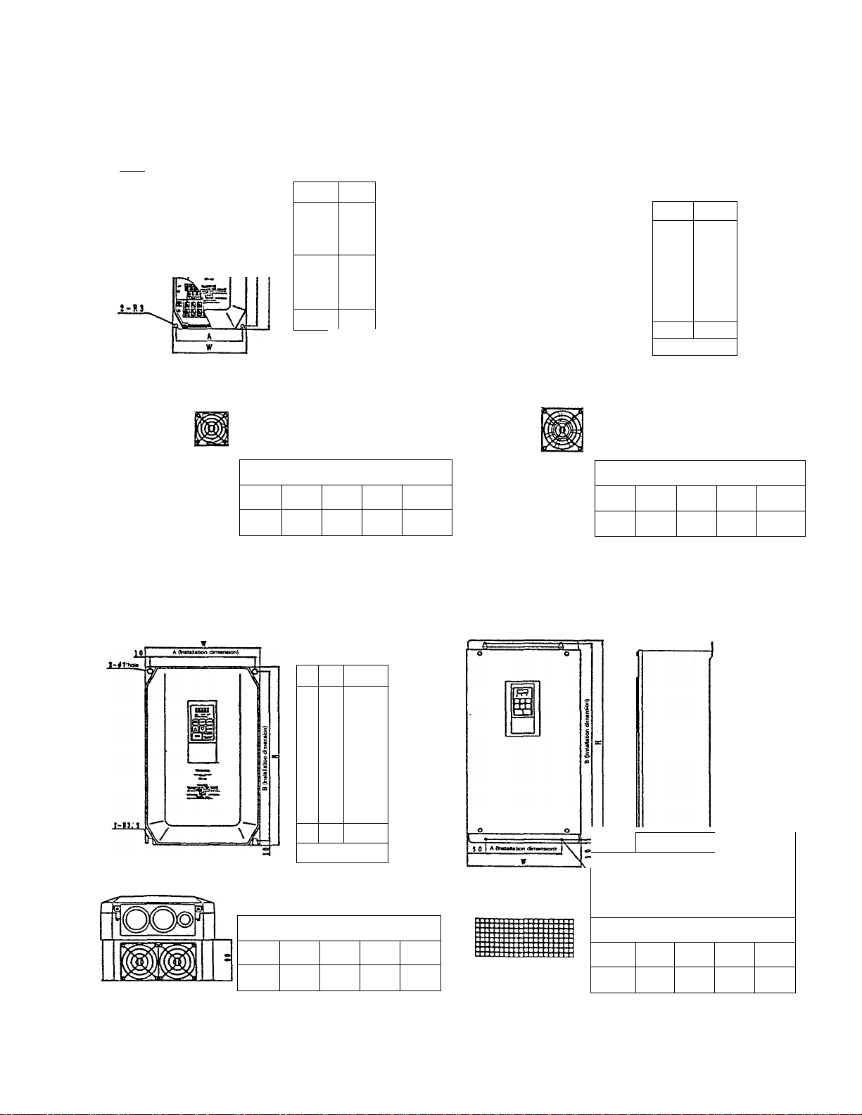
9.2 External Dimensions
3.7kW and smalier
t # g hew
Vi
1
Q
Model VFA5-2004-2037
- VFA5-4007-4037
\
■
rl
M
iB
□
0 Airflow direction
Dimensions (mm)
W H D
140 280 151
O
A B
126 266
5.5~7.5kW
A (InntBaiion dimeneion)
r
V
_____
QQQ
1
)A
200 280
Model VFA5-2055, 2075
\
rll
-=r
Dimensions (mm)
W H
VFA5-4055, 4075
■
11
■ □
O
D
D A B
167 186 266
Airflow
direction
11~18.5kW
Model VFA5-2110-2185
V
\
Dimensions (mm)
W
245
H
390
VFA5-4110-4185
Iii
Ilii
[-
lit
■
■
n
B
jc=o
____
D A
187 225
O
Airflow
direction
370
22, 30kW
2>ATheW
Model VFA5-2220, 2300
VFA5-4220, 4300
iii
Dimensions (mm)
B
W H D
300 555
197
A B
200 537
- 93
Page 100

37kW'
^-0l2 hole
.0KI
2-016 hole
Note)
This diagram is for the
VFA5-4450. The external
dimensions and terminal
configurations for other
models wilt vary.
WARNING
For safety reasons, unless making wiring
connections, please leave this cover installed at
all times.
Never remove this cover while the 'CHARGE*
lamp is lit.
When making wiring connections, please read the
wiring cautions on the back side of this cover.
Model
VFA5-2370
2450 375
2550 375
4370 375
4450
4550
4750 375
Dimensions (mm)
W
375
375
375 800 260
H D A
240
680
870 260 250 850
870 260 250 850
680 240 230 660
680 240 230
260
870
B
660
230
660
780
250
250 850
External Installation of
operating panel
' Panel dimensions
60 I t.^6
• Installation plate dimensions
________
Panel opening dimensions
-94-
 Loading...