


INSTALLATION MANUAL
MANUEL D’INSTALLATION
INSTALLATIONS-HANDBUCH
MANUALE DI INSTALLAZIONE
MANUAL DE INSTALACIÓN
MANUAL DE INSTALAÇÃO
INSTALLATIE HANDLEIDING
ΕΓΧΕΙΡΙΔΙΟ ΕΓΚΑΤΑΣΤΑΣΗΣ
Connection Interface Kit
Kit D’interface de Connexion
Verbindungsschnittstellen-Satz
Kit di Collegamento
Kit de Interfaz de Conexión
Kit de Interface de Ligação
Verbindingsinterfacekit
Κιτ Συνδέσμου Διασύνδεσης
(For RAV-SM***MUT)
MODEL:TCB-PX30MUE
English
CONTENTS
1 CAUTIONS ON SAFETY .............................................. 3
2 COMPONENTS ........................................................... 3
3 INSTALLATION PROCEDURE ..................................... 4
Français
Deutsch
Italiano
Español
Português
Nederlands
SOMMAIRE
1 CONSIGNES DE SÉCURITÉ ....................................... 7
2 COMPOSANTS ............................................................ 7
3 MÉTHODE D’INSTALLATION ...................................... 8
INHALT
1 SICHERHEITSHINWEISE .......................................... 11
2 BAUTEILE .................................................................. 11
3 MONTAGEVORGANG ............................................... 12
INDICE
1 AVVERTENZE PER LA SICUREZZA .......................... 15
2 COMPONENTI ........................................................... 15
3 PROCEDURA DI INSTALLAZIONE ............................ 16
CONTENIDO
1 PRECAUCIONES DE SEGURIDAD ............................ 19
2 COMPONENTES ....................................................... 19
3 PROCEDIMIENTO DE INSTALACIÓN ....................... 20
ÍNDICE
1 PRECAUÇÕES DE SEGURANÇA .............................. 23
2 COMPONENTES ....................................................... 23
3 PROCEDIMENTO DE INSTALAÇÃO ......................... 24
INHOUD
1 OPMERKINGEN IN VERBAND
MET DE VEILIGHEID ................................................. 27
2 COMPONENTEN ....................................................... 27
3 INSTALLATIEPROCEDURE ....................................... 28
ΕΛΛΗΝΙΚΑ
ΠΕΡΙΕΧΟΜΕΝΑ
1 ΠΡΟΦΥΛΑΞΕΙΣ ΑΣΦΑΛΕΙΑΣ ...................................... 31
2 ΕΞΑΡΤΗΜΑΤΑ ........................................................... 31
3 ∆ΙΑ∆ΙΚΑΣΙΑ ΕΓΚΑΤΑΣΤΑΣΗΣ .................................... 32
2
1
CAUTIONS ON SAFETY
• Before installation work, read this “Cautions on Safety” thoroughly.
• Strictly keep the following items in mind because they describe the
serious contents concerned with safety.
• After the installation work has been completed, perform a trial operation
to check for a possible problem. Following the Owner’s manual, explain
to the customers how to use the air conditioner.
• This Connection Interface Kit is a box that is used only for the purpose of
installing the TCB-PCNT30TLE2 (“1:1 model” connection interface) on
the Air Conditioner unit (RAV-SM***MUT-E).
• Before starting installation work, please read this Installation Manual and
Installation Manual of TCB-PCNT30TLE2 and install the product properly.
WARNING
• Carry out an installation work surely according to TCB-PCNT30TLE2
and this installation manual.
Inappropriate installation may result in water leakage, electric shock
or fire, etc.
• A person qualified in the electric work should execute the electric
works according to the Installation Manual and should use the
personal circuits.
The voltage shall be matched with the rated voltage of the product.
• Never modify or repair the product by yourself.
Incomplete modification or repair may result in an electric shock or fire.
ENGLISH
2
COMPONENTS
No
Connection Interface Kit
1
Connection Interface Kit Cover
2
Terminal block
3
Cross slot screw (M4x14)
4
Screw (M4x10)
5
Installation Manual
6
Connection cable A (5-wire, red & white)
7
Connection cable B (2-wire, blue)
8
Part Name
3
Q’ty
1
1
1
1
2
1
1
1
3
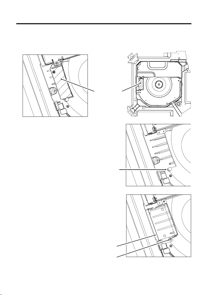
INSTALLATION PROCEDURE
1. Cut off the slit of bell mouth on the Air Conditioner unit
(RAV-SM***MUT-E) with a nipper or a cutter for attaching the
Connection Interface Kit.
Cutting off
portion
(Shaded
area)
After cutting off the slit of bell
mouth on the unit, clear up the
surface of the slit that there is
no burr on the cutting edge.
2. Attach the Connection Interface Kit
(TCB-PX30MUE) on the Air Conditioner
unit (RAV-SM***MUT-E).
After insert the hook of the unit to the
Connection Interface Kit hole, and then
tighten a Cross slot screw (4x14).
Connection Interface Kit
Cross slot screw
4

3. Install the spacers and P.C. board that are attached to the TCB-
PCNT30TLE2, on the Connection Interface Kit.
Spacers
(Attached to the
TCB-PCNT30TLE2)
P.C. board
(Attached to the
TCB-PCNT30TLE2)
4. Remove the 2P terminal block for
the communication cable of the
electric parts box on the unit, and
then replace with the attached 4P
terminal block for the
communication cable.
4-1. Disconnect the lead wires on
the 2P terminal block of the
electric parts box from the
Faston connector on the unit.
4-2. Replace the 2P connector
with 4P connector on the
terminal block.
CN41
(BLUE)
(A), (B) terminals (Connecting
for the Remote Controller)
4-3. Connect the lead wires that
are disconnected as shown
above steps 4-1, to the 4P
terminal block.
ENGLISH
CN41
(BLUE)
5

3
INSTALLATION PROCEDURE (Continue)
5. Connect the connection cables attached to the electric parts block.
31
31
CN41
54321
54321
TERMINAL
BA
CN50
(WHITE)
U3
U
CN50
(WHITE)
(U3), (U4) terminals
(For central control)
U3
U
4
MAIN P.C.B
MCC1402
4
CN51
CN41
(BLUE)
Connecting cable AConnecting cable B
54321
CN51
54321
SOB. P.C.B
MCC1440
WIRING DIAGRAM
6. Setting for Central Control
For Central Control setting, refer to the Installation Manual of the
TCB-PCNT30TLE2.
7. After the installation work has been completed, install the
Connection Interface Kit cover to the Connection Interface Kit
tightened with the two screws (4x10).
Screw (4x10)
Connection
Interface Kit cover
Hook of Connection
Interface Kit
Screw (4x10)
CN40
6

1
CONSIGNES DE SÉCURITÉ
•
Lisez attentivement ces « Consignes de sécurité » avant l’installation.
• Gardez ces consignes de sécurité à portée de main afin de vous y
reporter si nécessaire, car elles vous fournissent des informations
importantes concernant les mesures de sécurité.
• Une fois l’installation terminée, faites fonctionner l’appareil afin de
détecter d’éventuels problèmes. Lisez attentivement le Mode d’emploi
fourni, car il vous explique comment utiliser votre climatiseur.
• Ce kit d’interface de connexion est un boîtier qui permet d’installer le
TCB-PCNT30TLE2 (interface de connexion du modèle « 1:1 ») sur le
climatiseur (RAV-SM***MUT-E).
• Avant de commencer l’installation, lisez attentivement le présent Manuel
d’installation et le Manuel d’installation du TCB-PCNT30TLE2, puis
installez l’appareil.
ATTENTION
• Suivez les instructions d’installation du TCB-PCNT30TLE2 et du
présent Manuel d’installation.
Une mauvaise installation peut entraîner des fuites d’eau, une
électrocution, un incendie, etc.
• Confiez l’installation électrique à un électricien qualifié qui devra
suivre les instructions du Manuel d’installation et utiliser les
circuits personnels.
La tension électrique doit correspondre à la tension nominale de l’appareil.
• Ne démontez jamais l’appareil vous-même ; de plus, n’essayez
jamais de le réparer vous-même en cas de dysfonctionnement.
Le cas échéant, vous risqueriez de vous électrocuter ou de provoquer un incendie.
FRANÇAIS
2
COMPOSANTS
Nº
1
Kit d’interface de connexion
2
Couvercle du kit d’interface de connexion
Bloc de jonction
3
Vis à tête cruciforme (M4x14)
4
Vis (M4x10)
5
Manuel d’installation
6
Câble de connexion A (5 câbles, rouge et blanc)
7
Câble de connexion B (2 câbles, bleu)
8
Nom de la pièce
7
Quantité
1
1
1
1
2
1
1
1

3
MÉTHODE D’INSTALLATION
1. Coupez l’ouverture du pavillon sur le climatiseur
(RAV-SM***MUT-E) à l’aide d’une pince ou d’un cutter afin de fixer
le kit d’interface de connexion.
Portion
coupée
(zone
ombrée)
Après avoir coupé l’ouverture
du pavillon sur le climatiseur,
nettoyez la surface de
l’ouverture afin que la surface
soit lisse.
2. Fixez le kit d’interface de connexion
(TCB-PX30MUE) sur le climatiseur
(RAV-SM***MUT-E).
Insérez le crochet du climatiseur dans
l’orifice du kit d’interface de connexion,
puis fixez les deux éléments à l’aide
d’une vis à tête cruciforme (4x14).
Kit d’interface de connexion
Vis à tête cruciforme
8

3. Installez les entretoises et la carte à circuits imprimés fixées au
TCB-PCNT30TLE2 sur le kit d’interface de connexion.
Entretoises
(fixées au TCB-
PCNT30TLE2)
4. Retirez le bloc de jonction pour
câble de communication 2P du
boîtier électrique sur le
climatiseur, puis remplacez-le par
le bloc de jonction pour câble de
communication 4P.
4-1. Déconnectez les fils de sortie
sur le bloc de jonction 2P du
boîtier électrique du
connecteur Faston de l’unité.
4-2. Remplacez le connecteur 2P
par le connecteur 4P sur le
bloc de jonction.
4-3. Raccordez les fils de sortie
que vous avez déconnectés
comme indiqué aux étapes
4-1 ci-dessus, au bloc de
jonction 4P.
Carte à circuits
imprimés (fixée au
TCB-PCNT30TLE2)
CN41
(BLEU)
Bornes (A), (B) (connexion de
la télécommande)
FRANÇAIS
CN41
(BLEU)
9

3
MÉTHODE D’INSTALLATION (Suite)
5. Raccordez les câbles de connexion fixés au boîtier électrique.
31
31
CN41
54321
CN50
54321
(BLANC)
BORNE
CN50
(BLANC)
Bornes (U3), (U4) (pour
le contrôle central)
U3
U
4
MAIN P.C.B
MCC1402
U
4
BA
U3
CN51
CN41
(BLEU)
Câble de connexion B Câble de connexion A
54321
CN51
54321
SOB. P.C.B
MCC1440
SCHÉMA DE
CÂBLAGE
6. Réglages pour le contrôle central
Pour les réglages concernant le contrôle central, consultez le
Manuel d’installation du TCB-PCNT30TLE2.
7. Une fois l’installation terminée, installez le couvercle du kit
d’interface de connexion à l’aide des deux vis (4x10).
Vis (4x10)
Couvercle du kit
d’interface de
connexion
Crochets du kit
d’interface de
connexion
Vis (4x10)
CN40
10

EH99853101
 Loading...