

Page 1

AIR-DISCHARGE DIRECTION KIT FOR AIR CONDITIONER (SPLIT TYPE)
Installation Manual
Air-Discharge Direction Kit
(for 4-way air discharge cassette Type)
Model name:
Air-discharge direction kit
TCB-BC1602UUL
Installation Manual
Air-discharge direction kit 1
Manuel du proprietaire
Climatiseur
(Type à deux éléments) 7
English
Français
Page 2
Air-dischage direction kit
• Thank you for purchasing the “Air-discharge direction kit” of TOSHIBA/Carrier Air Conditioner. Before starting
the installation work, please read this manual carefully and install the product properly.
• As for the “Safety precaution”, please read the installation manual and the instruction manual for the 4-way air
discharge cassette type air conditioner (indoor unit) carefully, and also read the installation manual supplied with
the ceiling panel carefully.
• Please use this kit when controlling the air direction in 3-way or 2-way air flow depending on the installation
location status of the indoor unit.
Installation Manual
1 APPLICABLE MODELS AND
APPLECATIONS
MODEL Applicable model Application
TCB-BC1602UUL SP180 to SP420 Controlling the blockage of 3-way or 2-way air flow.
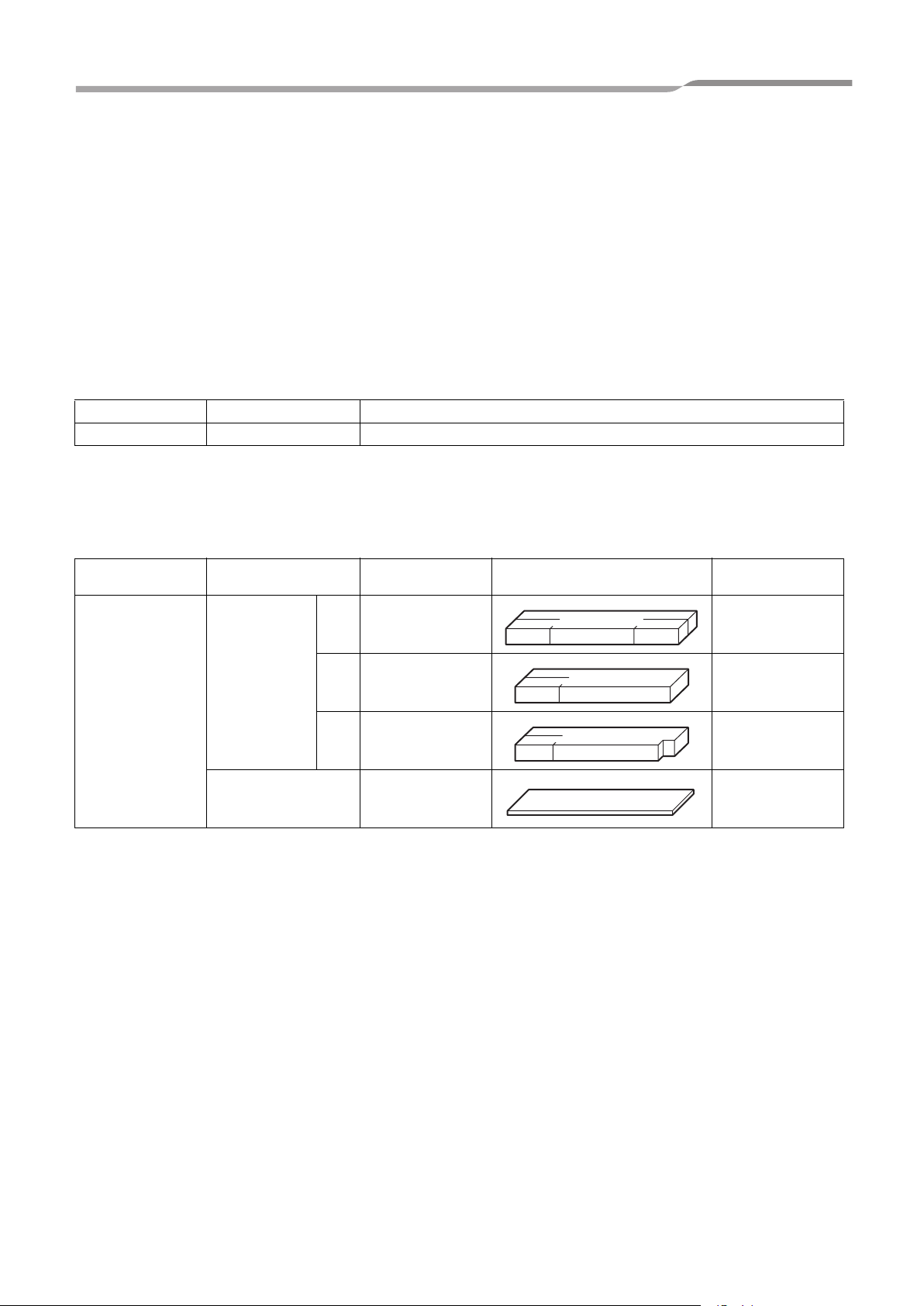
2 ACCESSORIES
The following parts are included.
MODEL Product name
Wind shield
TCB-BC1602UUL
Packing
Dimensions
18.9” x 3.2” x 1.6”
A
(480 × 80 × 40)
15.8” x 3.2” x 1.6”
B
(400 × 80 × 40)
15.8” x 3.2” x 1.6”
C
(400 × 80 × 40)
18.1” x 4.3” x 0.1”
(460 × 110 × 2)
(in (mm))
Shape Quantity
1
1
1
2
1-EN
–1–
Page 3
Air-dischage direction kit
Installation Manual
3 INSTALLATION METHODS
CAUTION
• Before installing the wind shield, change the air conditioner settings. Refer to “Changing the setting” on page 4.
• Unless the setting is changed, the air blow temperature becomes low. This may cause the dew condensation.
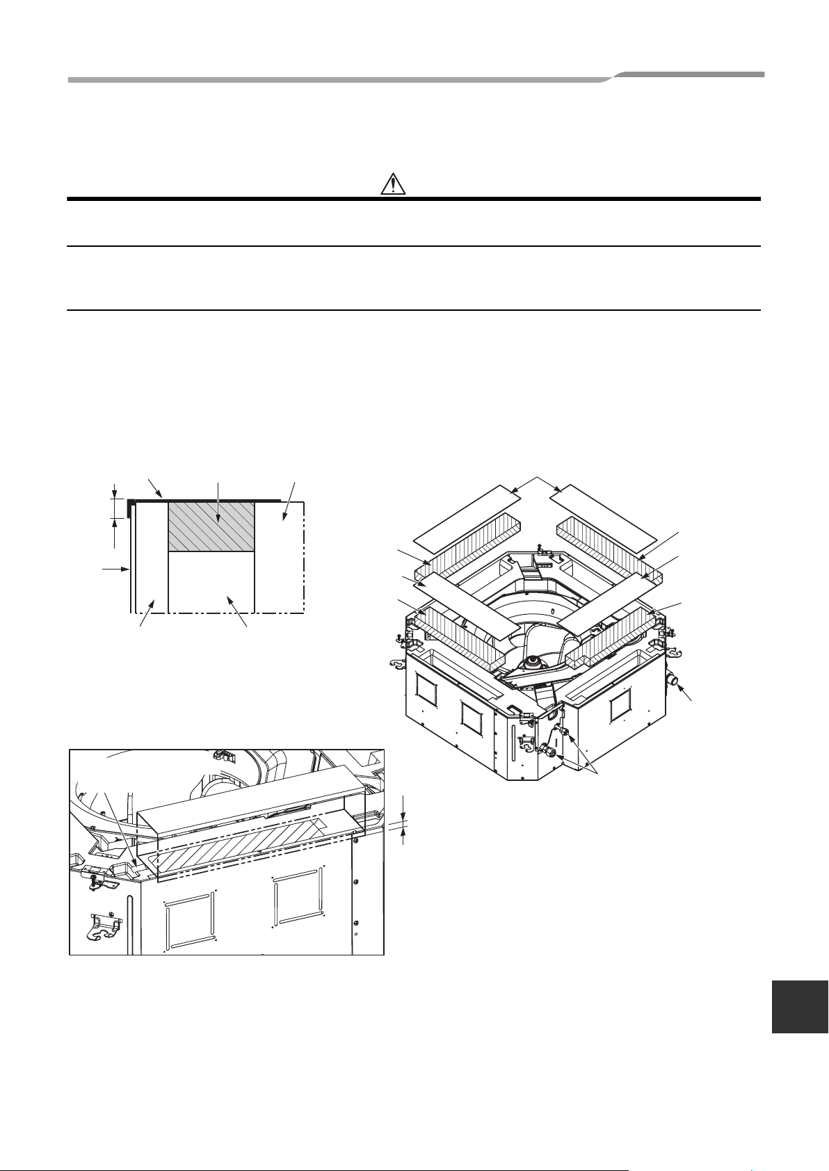
Installing the wind shield(s) and packings
• Attach the wind shields to the air flow openings (made of styrene foam) of the indoor unit and place the packings
on them to block the air flow. (Refer to Fig. 1 to 3.)
• Put the packings bending along the edges of the indoor unit external surface without blocking the concaved
portions of the drain pans. (If the packings are not put bending along the edge of the indoor unit external surface,
the dew condensation may occur.) (Refer to Fig. 1 and 3.)
* The size adjustment is required for the packing which are attached on the wind shield C. Cut 1.58” (40 mm) to
adjust its size in 16.5” x 4.3” (420 mm x 110 mm).
(Fig. 1) (Fig. 2)
Packing Wind shield (A, B, C) Drain pan
0.4” (10 mm)
Indoor
unit
External
surface
Interior styrene foam Air flow outlet
Wind shield A
Packing
Wind shield B
(Fig. 3)
Put the packings without
blocking the concaved
portions.
0.4” (10 mm)
Packing
Wind shield A
Packing
(required to cut
1.58” (40 mm.)
Wind shield C
Drain piping
Refrigerant piping
–2–
EN
2-EN
Page 4

Air-dischage direction kit
Installation Manual
Installing the indoor unit
• Install the indoor unit (Install the indoor unit following the instructions described on the installation manual of the
indoor unit.)
• Block the air flow outlets following the air flow blocking pattern shown in the table below when controlling 3-way
or 2-way air flow.
• The blockage portions of the air flow outlet are specified depending on the models. Do not specify the blockage
of the airflow outlet other than specified in the table below.
Limited models only
Wind shield A
3-way air flow
Wind shield B
Wind shield C
Wind shield A
2-way air flow
Available for all models Available for all models
Wind shield A
Wind shield B
Available for all models Available for all models Available for all models
Wind shield A
Wind shield C
Available only for
SP180 to SP240.
Wind shield B
Wind shield C
Available only for
SP300 to SP420.
3-EN
–3–
Page 5

Air-dischage direction kit
Installation Manual
Changing the setting
• The setting is changed by using a wired remote controller. (For the details, Refer to “Changing procedure”
described below.)
• Perform “Setting the louver lock (Louver position fixing)”.
CAUTION
When the ceiling is higher than the specification, the fan control is required. So, in that case, perform the “high ceiling
setting” other than the setting described below.
The setting should be performed according to the instructions described on the installation manual attached to the
indoor unit.
“Changing procedure”: Change the setting while the device stops.
1 Push + + buttons simultaneously for more than 4
sec.
The unit No. displayed at first shows the indoor unit address of the
header unit in group control operation. The fan operation of the
indoor unit (header unit), selected at this time, is carried out.
2 Every time when UNIT (Left button) is pushed, the No.
in the group cotrol operation are displayed in order.
The fan operation of the indoor unit, selected at this time, is carried
out.
3 Set the CODE No. by using the TEMP. / button.
4 Set the setting data by pushing TIME / buttons for the
TIME setting.
3-way air flow......................
2-way air flow......................
5 Push the button. (The setting completes if the setting
data are displayed.)
When changing the setting of other indoor unit in the group control
operation, return to
2.
6 Pushing the button enters to the normal stop status.
5
14 263
–4–
EN
4-EN
Page 6

Air-dischage direction kit
Installation Manual
Setting the louver lock (Louver position fixing)
• Fix the louver at the air flow blockage portions. (For the setting methods, follow the procedures below.)
1 Push the LOUVER (Right button) for more than
4 seconds while the air conditioner is stopped.
The blinks.
2 Push the UNIT (Left button) to select the indoor
unit you want to set.
Every time you push the button, the Unit No. changes.
The fan of the selected indoor unit starts its operation and the
louvers swing.
3 Push the TEMP. / buttons to display the
louver No. with the wind shield applied.
The selected louver starts to swing.
4 Select the code 0001 by pushing the TIME /
buttons.
5 Push the button to define the setting contents.
After the setting contents is defined, the mark lights.
(Return to step
3 if there are other two wind shields.)
6 Push the button to exit the setting.
“F1” is displayed in the CODE No. on the remote controller
display.
This means that the 01 louver shown on the illustration is
selected.
Unit No.
1-1
Unit No.
1-4
F1
F4
Louver fixing position code
Electric parts box
Refrigerant piping
Drain piping
Unit No.
1-2
Unit No.
1-3
F2
F3
Louver No.
(Louver No. diagram)
Confirming the installation
• After the installation completes, perform the test run to confirm that no abnormality is found.
• For your future reference, please keep the installation manual on your side.
5-EN
–5–
Page 7

Air-dischage direction kit
Installation Manual
MEMO
.....................................................................................................................
.....................................................................................................................
.....................................................................................................................
.....................................................................................................................
.....................................................................................................................
.....................................................................................................................
.....................................................................................................................
.....................................................................................................................
.....................................................................................................................
.....................................................................................................................
.....................................................................................................................
.....................................................................................................................
.....................................................................................................................
.....................................................................................................................
.....................................................................................................................
.....................................................................................................................
.....................................................................................................................
.....................................................................................................................
.....................................................................................................................
.....................................................................................................................
.....................................................................................................................
.....................................................................................................................
.....................................................................................................................
.....................................................................................................................
.....................................................................................................................
.....................................................................................................................
.....................................................................................................................
.....................................................................................................................
.....................................................................................................................
.....................................................................................................................
.....................................................................................................................
.....................................................................................................................
.....................................................................................................................
.....................................................................................................................
.....................................................................................................................
.....................................................................................................................
.....................................................................................................................
.....................................................................................................................
–6–
EN
Page 8

EH99678401
 Loading...