

Page 1
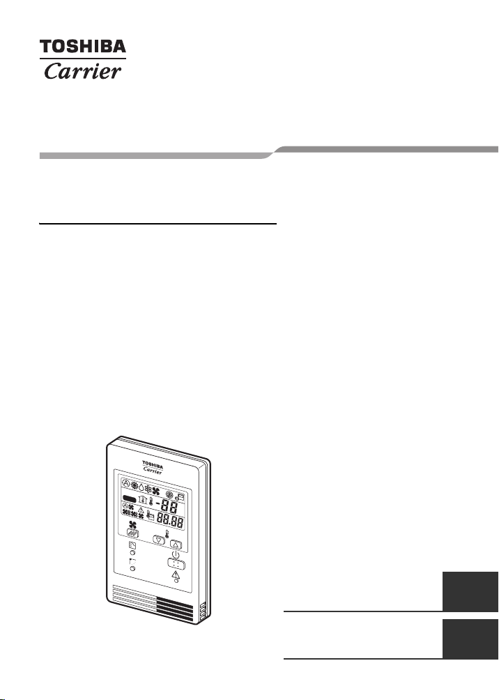
REMOTE CONTROLLER FOR AIR CONDITIONER (SPLIT TYPE)
Owner’s Manual
Remote Controller
Model name:
Simple wired remote
controller
RBC-AS21UL
TEST
S
E
TT
IN
G
°C
°F
Owner’s Manual
Remote controller for air
conditioner
Manuel du proprietaire
Télécommande pour
climatiseur
(Split type) 1
(Type split) 9
English
Français
Page 2
Simple wired remote controller
Thank you very much for purchasing TOSHIBA/Carrier Remote Controller
for Air Conditioner.
Please read this “Owner’s manual” carefully before using your Remote
Controller for Air Conditioner.
• Be sure to obtain the “Owner’s manual” and “Installation manual” from
constructor (or dealer).
Owner’s Manual
Request to constructor or dealer
• Please clearly explain the contents of the Owner's manual and hand over it.
Contents
1 PRECAUTIONS FOR SAFETY . . . . . . . . . . . . . . . . . . . . . . 2
2 PART NAMES AND FUNCTIONS. . . . . . . . . . . . . . . . . . . . 4
3 HOW TO OPERATE INDOOR UNIT . . . . . . . . . . . . . . . . . . 6
1-EN
–1–
Page 3
Simple wired remote controller
Owner’s Manual
1 PRECAUTIONS FOR SAFETY
WARNING
WARNINGS ABOUT INSTALLATION
• Make sure to ask the qualified installation professional in electric work to
install the remote controller.
If the remote controller is inappropriate installed by yourself, it may cause,
electric shock, fire, and so on.
• Make sure to install the air conditioner specified by TOSHIBA/Carrier and ask
the exclusive dealer when installing. If the air conditioner is installed by
yourself, it may cause electric shock or fire, etc.
WARNINGS ABOUT OPERATION
• Prevent any liquid from falling into the remote controller.
Do not spill juice, water or any kind of liquid.
It may cause machine failure, electric shock or fire, etc.
• When you are aware of an error with the air conditioner (smells like something
burning etc.), immediately turn off the circuit breaker to stop the air
conditioner, and make contact with the dealer. If the air conditioner is
continuously operated with something abnormal, it may cause malfunction,
electric shock, fire, and so on.
WARNINGS ABOUT MOVEMENT AND REPAIR
• Do not repair any unit by yourself.
Whenever the air conditioner needs repair, make sure to ask the dealer to do
it. If it is repaired imperfectly, it may cause electric shock or fire, etc.
• When reinstalling the air conditioner, contact with the dealer.
If the installation is insufficient, it may cause electric shock or fire, etc.
–2–
EN
2-EN
Page 4

Simple wired remote controller
Owner’s Manual
CAUTION
CAUTIONS ABOUT INSTALLATION
• Do not install the remote controller in a place where its signals do not reach
the indoor unit.
• Do not install the remote controller in a place under the direct sunlight or close
to any heat source. It may cause malfunction.
The fluorescent lamp with rapid start system or inverter system may disturb
the signal reception. For the details, contact with the dealer of the air
conditioner whom you have purchased it from.
CAUTIONS ABOUT OPERATION
• Do not drop or apply strong shock to the remote controller.
It may cause malfunction of the remote controller.
• Use batteries that meet the specifications.
3-EN
–3–
Page 5

Simple wired remote controller
7
6
5
4
Owner’s Manual
2 PART NAMES AND FUNCTIONS
Max. 8 indoor units can be operated by a remote controller.
Push each button to select a desired operation.
• The details of the operation needs to be set up once, afterward, the air
conditioner can be used by pushing ON/OFF button only.
Illustration of LCD shown below is for explanation. It may differ from the
actual LCD.
SETTING
1
2
3
1 Fan Speed button
2 Mode button
3 Swing/Air direction button
The louver angle is changed.
4 Setup temperature button
Adjust the set point.
Set the desired set point by pushing
or .
5 ON/OFF button
6 Check button (Used in
servicing)
Do not use this button usually.
7 Remote control temperature
sensor
Usually controlled by the indoor unit
sensor, it can be changed to the
remote controller. For details,
contact the shop which you
purchased the air conditioner. (When
using a group control method, do not
use the remote controller sensor.)
–4–
EN
4-EN
Page 6

Simple wired remote controller
Owner’s Manual
9
10
8 Operation mode
The selected operation mode is
displayed.
While is displayed, the indoor fan
stops or the mode is Low speed
mode.
9 Test run display
Displayed during a test run.
10
Error display
Displayed while the protective device
works or an error occurs.
11
is displayed during the
operation.
If the remote controller setting is
prohibited by the central remote
controller, flashes when [ON/
OFF], [Mode] or [Setup temperature]
button is pushed and change is not
accepted.
12
Set temperature display
The selected set temperature is
displayed.
8
SETTING
14 15
16
11
12
13
13
Error code display
Error code is displayed when an
error occurs.
14
Fan speed display
Selected fan speed, , ,
or is displayed.
15
Remote controller sensor
display
Displayed while the sensor of the
remote controller is used.
16
Pre-heat display
Displayed when the heating mode is
energized or defrost cycle is initiated.
While this indication is displayed, the
indoor fan stops.
• When turning on the power switch of
the simple operation type remote
controller at the first time,
flashes. While
the automatic model check is
operating.
Operate the remote controller after
SETTING
has
, disappeared.
SETTING
, is displayed,
SETTING
,
5-EN
–5–
Page 7

Simple wired remote controller
Owner’s Manual
3 HOW TO OPERATE INDOOR UNIT
COOL/HEAT AUTO ,
HEAT , DRY ,
COOL , FAN
Power supply
Turn on the power supply switch
12 hours before starting operations.
After the power supply has been
turned on, the operation of the remote
controller is not accepted for
approximately 1 minute. It is not a
failure.
(The sensor receives the signal once,
but the received contents are cleared.)
4
3
2
1
5
(During FAN mode, the fan speed is
not automatically changed.)
4 Push either or to select
a desired temperature.
During FAN mode, the temperature
cannot be set up.
5 Stop
Push , (ON/OFF) button.
When using the remote controller to
stop the unit, the outdoor unit fan
may keep operating for a while even
if the compressor of the outdoor unit
has stopped.
• In heating, if the room is not
comfortably heated with FAN ,
select FAN or .
Although they are displayed, the
function may not be provided
depending on the using indoor unit.
(Fan speed is constant.)
• When the unit cannot be stopped
by the normal operation.
Turn off the power switch or circuit
breaker, and then contact the shop
which you purchased the unit.
1 Push (ON/OFF) button.
2 Push (Mode) button to select
operation to , , , or
.
3 Push (Fan Speed) button to
select fan speed mode.
When selecting , fan speed is
automatically changed.
–6–
EN
6-EN
Page 8

Simple wired remote controller
Automatic Cool/Heat
When all indoor units in the identical
refrigerant system are controlled as a
group, the cooling or heating operation
is automatically performed with the
difference between the setup
temperature and the room
temperature.
Dry operation
• Dry function may not be provided
depending on the using indoor unit,
even if Dry ( ) is displayed on the
LCD of the remote controller. (The
same to Cooling operation)
• When the room temperature
approaches the setup temperature,
it automatically repeats to ON/OFF
operations.
• In order not to return humidity to the
room as possible, the mode of
indoor fan changes to LOW when
the operation has stopped.
• The fan speed may not be
adjustable depending on the using
indoor unit or the room temperature.
• The Dry mode may not be available
depending on the using indoor unit
when the outdoor temperature is
59 °F (15 °C) or lower.
Owner’s Manual
7-EN
–7–
Page 9

Simple wired remote controller
Owner’s Manual
MEMO
.......................................................................
.......................................................................
.......................................................................
.......................................................................
.......................................................................
.......................................................................
.......................................................................
.......................................................................
.......................................................................
.......................................................................
.......................................................................
.......................................................................
.......................................................................
.......................................................................
.......................................................................
.......................................................................
.......................................................................
.......................................................................
.......................................................................
.......................................................................
.......................................................................
.......................................................................
.......................................................................
–8–
EN
8-EN
Page 10

85464609011000
(EH99677101)
 Loading...