


QOSMIO X500
Table of contents
 Loading...
Qosmio X500
Maintenance Manual (960-Q08)
Toshiba Personal Computer
Qosmio X500
Maintenance Manual
TOSHIBA CORPORATION
File Number 960-Q08

Qosmio X500
Maintenance Manual (960-Q08)
Copyright
© 2009 by Toshiba Corporation. All rights reserved. Under the copyright laws, this manual
cannot be reproduced in any form without the prior written permission of Toshiba. No patent
liability is assumed with respect to the use of the information contained herein.
Toshiba Personal Computer Qosmio X500 Maintenance Manual
First edition Aug. 2009
Disclaimer
The information presented in this manual has been reviewed and validated for accuracy. The
included set of instructions and descriptions are accurate for the Qosmio X500 series at the
time of this manual's production. However, succeeding computers and manuals are subject
to change without notice. Therefore, Toshiba assumes no liability for damages incurred
directly or indirectly from errors, omissions, or discrepancies between any succeeding
product and this manual.
Trademarks
Intel, Intel SpeedStep, Intel Core, Pentium and Celeron are trademarks or registered
trademarks of Intel Corporation or its subsidiaries in the United States and other
countries/regions.Windows and Microsoft are registered trademarks of Microsoft
Corporation.
Other trademarks and registered trademarks not listed above may be used in this manual.

Qosmio X500
Maintenance Manual (960-Q08)
Preface
This maintenance manual describes how to perform hardware service maintenance for the
Toshiba Personal Computer Qosmio X500 Series.
The procedures described in this manual are intended to help service technicians isolate
faulty Field Replaceable Units (FRUs) and replace them in the field.
SAFETY PRECAUTIONS
Four types of messages are used in this m
anual to bring important information to your
attention. Each of these messages will be italicized and identified as shown below.
DANGER: “Danger” indicates the existence of a hazard that could result in death or
serious bodily injury, if the safety instruction is not observed.
WARNING: “Warning” indicates the existence of a hazard that could result in bodily
injury, if the safety instruction is not observed.
CAUTION: “Caution” indicates the existence of a hazard that could result in property
damage, if the safety instruction is not observed.
NOTE: “Note” contains general information that relates to your safe maintenance
service.
Improper repair of the computer may result in safety hazards. Toshiba requires service
technicians and authorized dealers or service providers to ensure the following safety
precautions are adhered to strictly.
Be sure to fasten screws securely with the right screwdriver. If a screw is not fully
fastened, it could come loose, creating a danger of a short circuit, which could cause
overheating, smoke or fire.
If you replace the battery pack or RTC battery, be sure to use only the same model
battery or an equivalent battery recommended by Toshiba. Installation of the wrong
battery can cause the battery to explode.

Qosmio X500
Maintenance Manual (960-Q08)
The manual is divided into the following parts:
Chapter 1 Hardware Overview describes the Qosmio X500 system unit and each
FRU.
Chapter 2 Troubleshooting Procedures explains how to diagnose and resolve
FRU problems.
Chapter 3 Test and Diagnostics describes how to perform test and diagnostic
operations for maintenance service.
Chapter 4 Replacement Procedures describes the removal and replacement of the
FRUs.
Appendices The appendices describe the following:
Handling the LCD Module
Board layout
Pin assignments
Keyboard scan/character codes
Key layout
Wiring diagrams

Qosmio X500
Maintenance Manual (960-Q08)
Conventions
This manual uses the following formats to describe, identify, and highlight terms and
operating procedures.
Acronyms
On the first appearance and whenever necessary for clarification acronyms are enclosed in
parentheses following their definition. For example:
Read Only Memory (ROM)
Keys
Keys are used in the text to describe many operations. The key top sym
bol as it appears on
the keyboard is printed in boldface type.
Key operation
Some
operations require you to simultaneously use two or more keys. We identify such
operations by the key top symbols separated by a plus (+) sign. For example, Ctrl + Pause
(Break) means you must hold down Ctrl and at the same time press Pause (Break). If
three keys are used, hold down the first two and at the same time press the third.
User input
Text that you are instructed to type in is shown in the boldface type below:
DISK COPY A: B:
The display
Text generated by the computer that appears on its display is presented in the typeface
below:
Format complete
System transferred

Qosmio X500
Maintenance Manual (960-Q08)
Table of Contents
Chapter 1 Contents
1.1 Features..........................................................................................................................1
1.2 System Block Diagram..................................................................................................5
1.3 2.5-inch Hard Disk Drive...............................................................................................8
1.4 Optical Drive................................................................................................................11
1.5 Keyboard......................................................................................................................16
1.6 TFT Color Display.......................................................................................................17
1.6.1 LCD Module With CCFL Backlight...........................................................17
1.6.2 CCFL Inverter Board..................................................................................19
1.7 Power Supply...............................................................................................................20
1.8 Batteries .......................................................................................................................21
1.8.1 Main Battery ...............................................................................................21
1.8.2 Battery Charging Control............................................................................22
1.8.3 RTC battery.................................................................................................24
1.9 AC Adapter ..................................................................................................................25

Qosmio X500
Maintenance Manual (960-Q08)
Chapter 2 Troubleshooting Procedures
2.1 Troubleshooting............................................................................................................1
2.2 Troubleshooting Flowchart........................................................................................... 3
2.3 Power Supply Troubleshooting..................................................................................... 7
Procedure 1 Power Status Check .......................................................................... 7
Procedure 2 Connection Check............................................................................. 9
Procedure 3 Charging Check .............................................................................. 10
Procedure 4 Replacement Check ........................................................................ 11
2.4 System Board Troubleshooting...................................................................................12
Procedure 1 Message Check ............................................................................... 13
Procedure 2 Debugging Port Check....................................................................14
Procedure 3 Replacement Check ........................................................................ 14
2.5 USB FDD Troubleshooting ........................................................................................ 15
Procedure 1 FDD Head Cleaning Check ............................................................ 15
Procedure 2 Diagnostic Test Program Execution Check.................................... 16
Procedure 3 Connector Check and Replacement Check..................................... 17
2.6 2.5” HDD Troubleshooting......................................................................................... 19
Procedure 1 Partition Check................................................................................ 19
Procedure 2 Message Check ............................................................................... 20
Procedure 3 Format Check.................................................................................. 21
Procedure 4 Diagnostic Test Program Execution Check.................................... 22
Procedure 5 Connector Check and Replacement Check..................................... 23
2.7 Keyboard Troubleshooting ......................................................................................... 24
Procedure 1 Diagnostic Test Program Execution Check.................................... 24
Procedure 2 Connector Check and Replacement Check..................................... 25
2.8 Touch pad Troubleshooting........................................................................................ 26
Procedure 1 Diagnostic Test Program Execution Check.................................... 26
Procedure 2 Connector Check and Replacement Check..................................... 27

Qosmio X500
Maintenance Manual (960-Q08)
2.9 Display Troubleshooting..............................................................................................28
Procedure 1 External Monitor Check...................................................................28
Procedure 2 Diagnostic Test Program Execution Check.....................................28
Procedure 3 Connector and Cable Check ............................................................29
Procedure 4 Replacement Check .........................................................................30
2.10 Optical Disk Drive Troubleshooting............................................................................31
Procedure 1 Diagnostic Test Program Execution Check.....................................31
Procedure 2 Connector Check and Replacement Check......................................31
2.11 Modem Troubleshooting..............................................................................................32
Procedure 1 Diagnostic Test Program Execution Check.....................................32
Procedure 2 Connector Check and Replacement Check......................................32
2.12 LAN Troubleshooting..................................................................................................34
Procedure 1 Diagnostic Test Program Execution Check.....................................34
Procedure 2 Connector Check and Replacement Check......................................34
2.13 Wireless LAN Troubleshooting...................................................................................35
Procedure 1 Transmitting-Receiving Check........................................................35
Procedure 2 Antennas' Connection Check...........................................................36
Procedure 3 Replacement Check .........................................................................37
2.14 Sound Troubleshooting................................................................................................38
Procedure 1 Connector Check..............................................................................38
Procedure 2 Replacement Check .........................................................................39
2.15 Fingerprint Troubleshooting........................................................................................40
Procedure 1 Diagnostic Test Program Execution Check.....................................40
Procedure 2 Connector Check and Replacement Check.....................................40
2.16 Bluetooth Troubleshooting..........................................................................................41
Procedure 1 Connector Check and Replacement Check.....................................41

Qosmio X500
Maintenance Manual (960-Q08)
Chapter 3 Diagnostic Programs
3.1 Tests and Diagnostics Software Overview..............3-Error! Bookmark not defined.
3.2 Executing the Diagnostic Test................................. 3-Error! Bookmark not defined.
3.3 Subtest names........................................................... 3-Error! Bookmark not defined.
3.4 System Test..............................................................3-Error! Bookmark not defined.
3.5 Memory Test............................................................3-Error! Bookmark not defined.
3.6 Keyboard Test..........................................................................................................3-22
3.7 Display Test.............................................................................................................3-25
3.8 Floppy Disk Test......................................................................................................3-40
3.9 Hard Disk Test......................................................................................................... 3-42
3.10 Real Time Clock Test..............................................................................................3-45
3.11 Cache Memory Test.................................................3-Error! Bookmark not defined.
3.12 High Resolution Display Test.................................. 3-Error! Bookmark not defined.
3.13 Multimedia Test.......................................................................................................3-55
3.14 MEMORY2 Test...................................................... 3-Error! Bookmark not defined.
3.15 Error Codes and Error Status Names.......................3-Error! Bookmark not defined.
3.16 Running Test............................................................................................................3-60
3.17 DMI INFOEMATION............................................. 3-Error! Bookmark not defined.
3.17.1 Check DMI Information .............. 3-Error! Bookmark not defined.
3.17.2 Write DMI Information................ 3-Error! Bookmark not defined.
3.18 Log Utilities............................................................................................................. 3-63
3.18.1 Operations....................................................................................3-63
3.19 System Configuration..............................................................................................3-65
3.20 Running Test Edit Item............................................ 3-Error! Bookmark not defined.
3.20.1 Function Description
.................... 3-Error! Bookmark not defined.
3.20.2 Operation Description..................3-Error! Bookmark not defined.
3.21 Common Tests and Operation ................................. 3-Error! Bookmark not defined.
3.21.1 How to operate a window............ 3-Error! Bookmark not defined.
3.21.2 How to Stop the Test Program.....3-Error! Bookmark not defined.
3.21.3 Test Status Screen........................ 3-Error! Bookmark not defined.
3.21.4 Test Stop Display.........................................................................3-70
3.21.5 How to enter data.........................................................................3-70

Qosmio X500
Maintenance Manual (960-Q08)
Chapter 4 Replacement Procedures
4.1 Overview....................................................................................................................4-1
Safety Precautions................................................................................................ 4-2
Before You Begin................................................................................................4-3
Disassembly Procedure........................................................................................4-4
Assembly Procedure ............................................................................................4-5
Tools and Equipment........................................................................................... 4-5
Screw Tightening Torque .................................................................................... 4-6
Grip Color….......... ……………………………………………………………..4-6
Screw Notation ....................................................................................................4-7
4.2 Battery pack............................................................................................................... 4-8
4.3 PC card.....................................................................................................................4-10
4.4 SSD/HDD(MAIN HDD) ......................................................................................... 4-12
4.5 Optical disk drive.....................................................................................................4-16
4.6 Slot in optical disk drive.......................................................................................... 4-18
4.7 HDD(SECOND HDD)............................................................................................ 4-21
4.8 Memory module....................................................................................................... 4-25
4.9 Keyboard.................................................................................................................. 4-28
4.10 Wireless LAN card ..................................................................................................4-31
4.11 Bluetooth module..................................................................................................... 4-34
4.12 TV Tuner card.......................................................................................................... 4-35
4.13 Display assembly..................................................................................................... 4-37
4.14 Top Cover assembly ................................................................................................ 4-42
4.15 Touch pad.................................................................................................................4-45
4.16 USB Board ...............................................................................................................4-48
4.17 B CAS Board ........................................................................................................... 4-49
4.18 System Board...........................................................................................................4-50
4.19 CPU..........................................................................................................................4-54
4.20 LCD unit / FL inverter............................................................................................. 4-57

Qosmio X500
Maintenance Manual (960-Q08)
4.21 Web Camera module................................................................................................4-62
4.22 Speaker Box.............................................................................................................4-64
4.23 Application for thermal pad and grease on CPU, North Bridge, and VGA
Board………………………………………………………………………….........4-
67

Qosmio X500
Maintenance Manual (960-Q08)
Appendices
Appendix A Handling the LCD Module ........................................................................... A-1
Appendix B Board Layout .................................................................................................B-1
Appendix C Pin Assignments.............................................................................................C-1
Appendix D Keyboard Scan/Character Codes.................................................................. D-1
Appendix E Key Layout.....................................................................................................E-1
Appendix F Wiring Diagrams............................................................................................F-1

Qosmio X500
Maintenance Manual (960-Q08)

Qosmio X500
Maintenance Manual (960-Q08)
Chapter 1
Hardware Overview

Chapter 1 Hardware Overview
Qosmio X500
Maintenance Manual (960-Q08)
ii
1 Hardware Overview
Chapter 1 Contents
1.1 Features..........................................................................................................................1
1.2 System Block Diagram..................................................................................................5
1.3 2.5-inch Hard Disk Drive...............................................................................................8
1.4 Optical Drive................................................................................................................11
1.5 Keyboard......................................................................................................................16
1.6 TFT Color Display.......................................................................................................17
1.6.1 LCD Module With CCFL Backlight......................................................17
1.6.2 CCFL Inverter Board .............................................................................19
1.7 Power Supply...............................................................................................................20
1.8 Batteries .......................................................................................................................21
1.8.1 Main Battery...........................................................................................21
1.8.2 Battery Charging Control.......................................................................22
1.8.3 RTC battery............................................................................................24
1.9 AC Adapter ..................................................................................................................25

Hardware Overview Chapter 1
Qosmio X500
Maintenance Manual (960-Q08)
iii
Figures
Figure 1-1-1 Front of the computer.........................................................................................4
Figure 1-2-1 System block diagram for AMD platform.........................................................5
Figure 1-3-1 2.5-inch HDD Disk Drive..................................................................................8
Figure 1-4-1 DVD Super Muti drive.....................................................................................11
Figure 1-5-1 Keyboard for US Style.....................................................................................16
Figure 1-5-2 Keyboard for UK Style....................................................................................16
Figure 1-6-1 SAMSUNG LCD Module................................................................................17
Tables
Table 1-3-2 2.5-inch HDD dimensions .................................................................................8
Table 1-3-3 2.5-inch HDD specifications..............................................................................9
Table 1-4-2 DVD Super Multi drive outline dimensions....................................................12
Table 1-4-3 HLDS DVD Super Multi drive specifications.................................................13
Table 1-4-4 Panasonic DVD Super Multi drive specifications...........................................14
Table 1-4-5 TSST DVD Super Multi drive specifications..................................................15
Table 1-6-2 LCD module specifications..............................................................................18
Table 1-6-3 FL inverter board specifications ......................................................................19
Table 1-7-1 Power supply output rating..............................................................................20
Table 1-8-1 Battery specifications.......................................................................................21
Table 1-8-2 Time required for charges of main battery ......................................................22
Table 1-8-3 Data retaining time...........................................................................................23
Table 1-8-4 Time required for charges of RTC battery.......................................................24
Table 1-9-1 AC adapter specifications ................................................................................25

Chapter 1 Hardware Overview
Qosmio X500
Maintenance Manual (960-Q08)
1
Features
1.1 Features
The Qosmio X500 features are listed below.
Microprocessor
Microprocessor that is used will be different by the model.
It supports processors as follows
Intel® Core(TM) i7-720QM processor
1.6GHZ,1.73GHz
Additional processor may be introduced
Memory
Two DDR3 SO-DIMM (1066MHz specification compliant) used and be up to 4GB
which can be upgraded through Memory Module Slot. Maximum upgradeable system
memory may depend on the model
VRAM
Shared with System memory for Intel PM55.
HDD
5400rpm: 250GB, 320GB, 400GB, 500GB, internal drives. 2.5 inch x 9.5mm height.
USB FDD
Toshiba external USB FDD for option
Display
18.4” Wide WXGA
1-Lamp HD+ ( 1680 x 945) CSV only (Typical 200 NIT brightness)
2-Lamp FHD ( 1920 x 1080) CSV only (Typical 300 NIT brightness)
External monitor
Supported via a RGB or HDMI connector.
Keyboard

Chapter 1 Hardware Overview
Qosmio X500
Maintenance Manual (960-Q08)
2
Keyboard module has104/105/109 keys. It supports Windows keys and application
keys.
New Dummy card slot
The new card slot (dummy card) accommodates express card.
Optical devices
A DVD Super Multi drive is equipped.
Battery
The RTC battery is equipped inside the computer.
The main battery is a detachable lithium ion battery.
12 cell Li-Ion 10.8v
USB (Universal Serial Bus)
4 USB ports are provided. The ports comply with the USB2.0 standard,
USB Sleep and Charge function can be supported by only one port of the left
side.(mode 1-4)
If USB Sleep and Charge function is enabled, the computer’s battery will discharge
during hibernation or when the computer is turned off. It is recommended that user
connect the AC adaptor to the computer when enabling the USB Sleep and Charge
function.ESATA
One ESATA port is equipped.
Sound system
Internal stereo speaker, Internal MIC external monaural microphone connector, stereo
headphone connector.
Wireless LAN
Some computers in this series are equipped with a Wireless LAN card.
LAN/MODEM
Connectors for LAN and Modem are separately mounted.
1394
One 1394 port is equipped.

Chapter 1 Hardware Overview
Qosmio X500
Maintenance Manual (960-Q08)
3
Bridge media slot
XD/MS/MS pro/SD/MMC are supported
Bluetooth
Some computers in this series offer Bluetooth wireless communication functionality.
This module is Version 2.1+EDR.
Security
Kensington Lock,
Fingerprint –Enhanced Lock is also equipped.
HDD password
HDD security function
Chapter 1 Hardware Overview
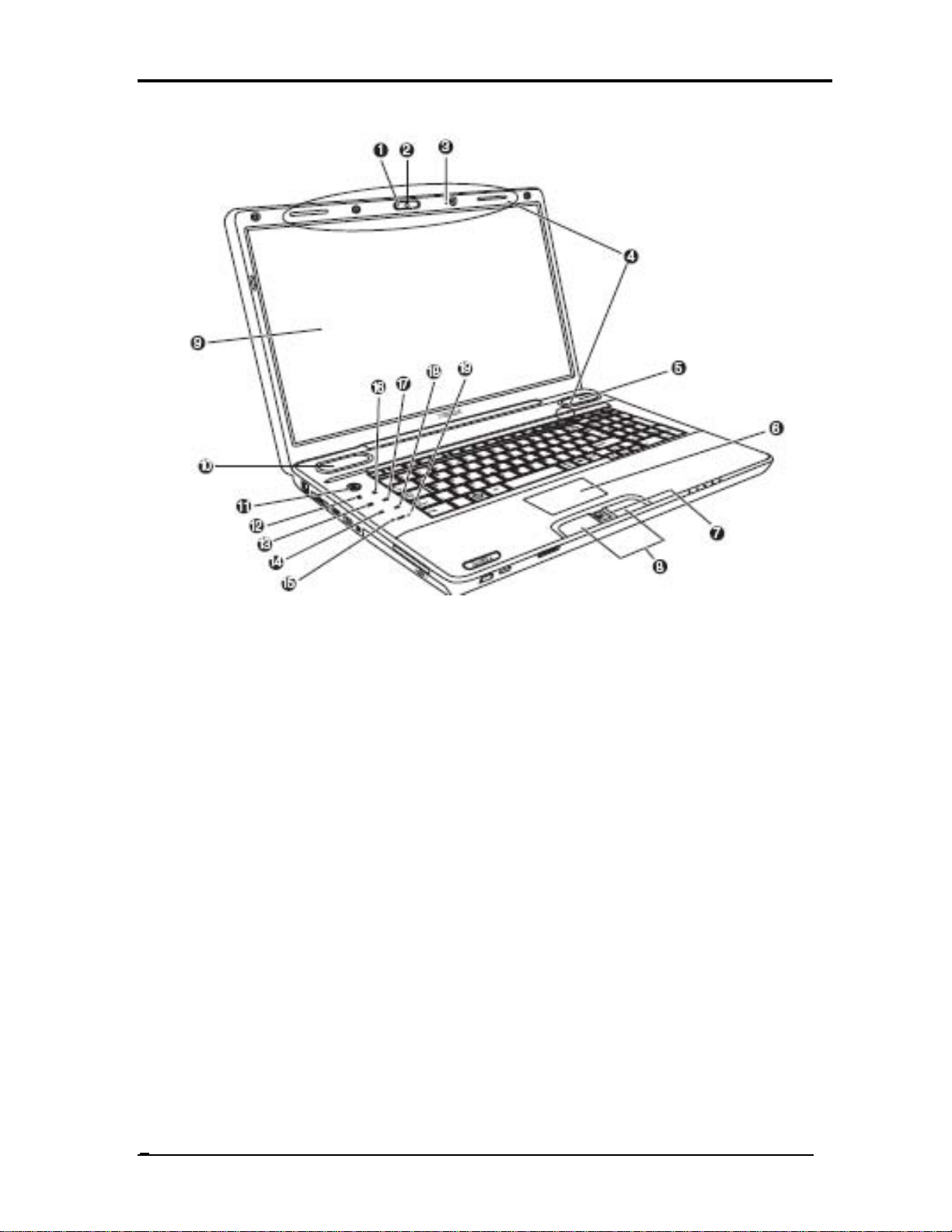
1. Web Camera LED* 2. Web Camera*
3. Built-in microphone* 4. Wireless LAN/Wireless WAN Antennas (Not shown)
5. Speaker 6. Touch Pad
7. Fingerprint Sensor* 8. Touch Pad Control Buttons
9. Display Screen 10. Speaker
11. Power Button* 12. Internet Button*
13. CD/ DVD Button* 14. Previous Button*
15. Volume Down Button* 16. Mute Button*
17. Play/Pause Button* 18. Next Button* 19. Volume Up Button*
Figure 1-1-1 Front of the computer
Qosmio X500
Maintenance Manual (960-Q08)
4
Chapter 1 Hardware Overview
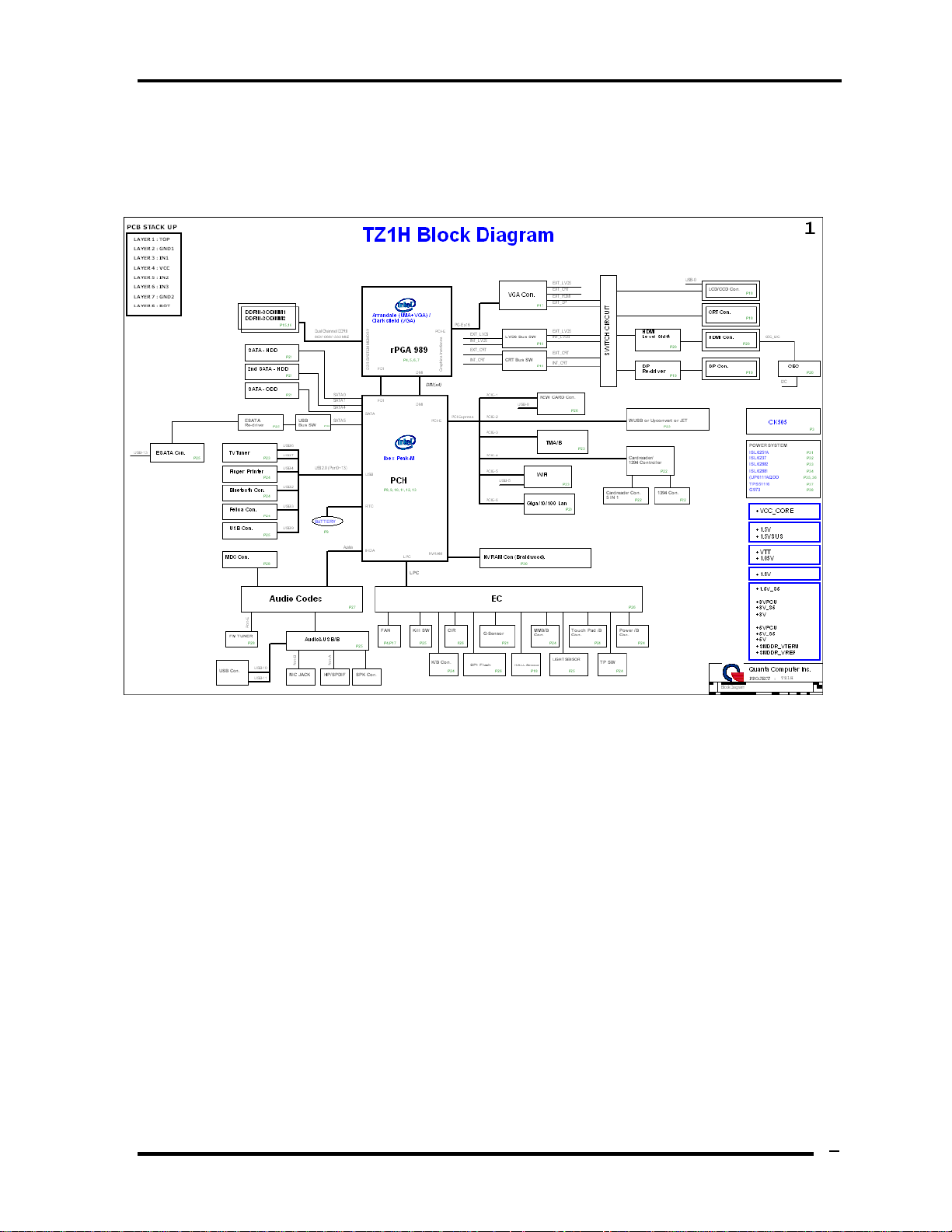
1.2 System Block Diagram
Figure 1-2-1 shows the system block diagram.
Figure 1-2-1 System block diagram for Intel Platform
5
Qosmio X500
Maintenance Manual (960-Q08)

Chapter 1 Hardware Overview
Qosmio X500
Maintenance Manual (960-Q08)
6
The PC contains the following components.
CPU
Intel® Core(TM) i7-720QM processor
1.6GHz, 1.73GHz
Memory
DDR3-1066MHz 1GB, 2GB or 4GB memory modules
200-pin SO-DIMM
1.8V operation
BIOS ROM (Flash memory)
16Mbit
Chipset
North Bridge
Penryn processor System Bus support
DRAM Controller : DDR3 1066MHz support
DMI
1299-ball 35 x 35mm Mirco FC-BGA Package
South Bridge
Direct Media Interface (DMI)
PCI Express
Serial ATA Controller
PCI Interface
Low Pin count (LPC) interface
Serial Peripheral Interface (SPI)
DMA controller
Advanced Programmable Interrupt Controller (APIC)
USB Controllers
Gigabit Ethernet Controller
RTC
GPIO
Enhanced Power Management
SMBus 2.0
High Definition Audio Controller
676-pin 31mmx31mm mBGA Package

Chapter 1 Hardware Overview
Qosmio X500
Maintenance Manual (960-Q08)
7
Other main system chips
• Clock Generator
• EC/KBC –[W/CIR(Winbond WPCE775CA0DG)] –[WO/CIR(Winbond
WPCE775LA0DG)]
• HD Audio (CONEXANT CX20583-10Z)
• Card Reader controller (O2 OZ888GS0LN)
• 10/100 LAN controller (Atheros AR8132M)
• Giga LAN controller (Atheros AR8131M)
Mini Card
Wireless LAN (BTO)
DSSS/OFDM LAN card is equipped. Conformity with IEEE 802.11b/g, IEEE
802.11 a/g/n or IEEE 802.11a/b/g..
MODEM (Conexant x 1)
Supported by on board Modem + DAA daughter card.
Data and FAX transmission is available.
Supports ITU-TV.92.
The transfer speed of data receiving is 56kbps, of data sending is 33.6kbps and of
FAX is 14.4kbps. Actual speed depends on the quality of the line used.
Connected to telephone line through RJ11 MOD
Bluetooth
Bluetooth V2.1+EDR. (BTO)
Chapter 1 Hardware Overview
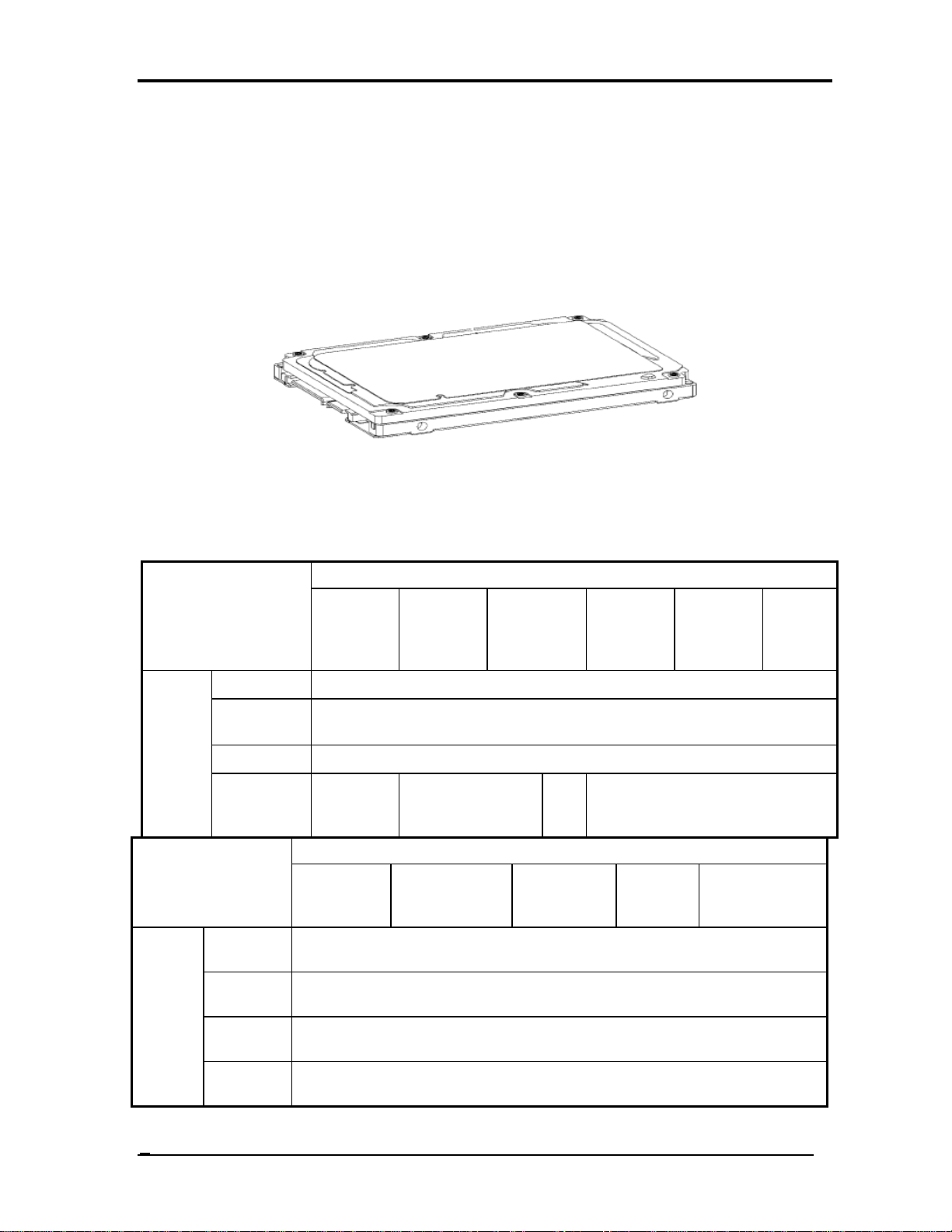
1.3 2.5-inch Hard Disk Drive
A compact, high-capacity HDD with a height of 9.5mm. Contains a 2.5-inch magnetic disk
and magnetic heads.
Figure 1-3-1 shows a view of the 2.5-inch HDD and Tables 1-3-2 and 1-3-3 list the
specifications.
Figure 1-3-1 2.5-inch HDD
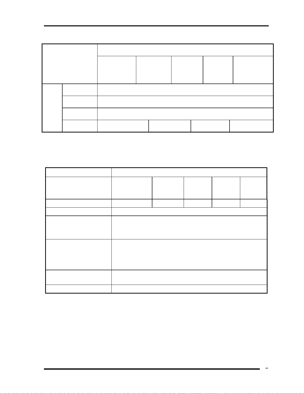
Table 1-3-2 2.5-inch HDD dimensions
Standard value
Parameter
TOSHIBA
MK1655G
SX
TOSHIBA
MK2555G
SX
TOSHIBA
MK3255GS
X
TOSHIBA
MK4055G
SX
TOSHIBA
MK3263G
SX
TOSHIB
A
MK5055
GSX
Width (mm)
69.85 +/- 0.25
Height
(mm)
9.5
Depth (mm)
100.2 +/- 0.25
Outline
dimens
ions
Weight (g)
97/98 97/98
101
//10
2
101//102
Standard value Parameter
FUJITSU
MJA2160B
H
FUJITSU
MJA2250BH
FUJITSU
MJA2320B
H
FUJITSU
MJA240
0BH
FUJITSU
MJA2500BH
Width
(mm)
100
Height
(mm)
9.5
Depth
(mm)
70
Outline
dimensi
ons
Weight
(g)
101(Max)
Qosmio X500
Maintenance Manual (960-Q08)
8
Chapter 1 Hardware Overview
Qosmio X500
Maintenance Manual (960-Q08)
9
Standard value Parameter
HITACHI
HTS545016B9A
300
HITACHI
HTS545025B9
A300
HITACHI
HTS545032
B9A300
HITACHI
HTS545040
B9A300
HITACHI
HTS545050B9A
300
Width (mm)
69.85 +/- 0.25
Height (mm)
9.5
Depth (mm)
100.2 +/- 0.25
Outlin
e
dimen
sions
Weight (g)
95 (max.) 95 (max.)
102 (max.) 102 (max.)
Table 1-3-3 2.5-inch HDD specifications
Specification
Parameter
TOSHIBA
MK1655GSX
TOSHIBA
MK2555GS
X
TOSHIBA
MK3255G
SX
TOSHIBA
MK4055G
SX
TOSHIBA
MK5055G
SX
Storage size (formatted) 160GB 250GB 320GB 400 GB 500GB
Speed (RPM) 5,400
Data transfer Rate
- To/From Media
- T0/From Host
363~952 typical
3Gbps (150MB/s)
bus transfer rate (MB/s)
3Gbps(150MB/s)
Average random seek time
(read) (ms)
12
Power-on-to-ready (sec) 3.5(typ)/9.5(Max)
Chapter 1 Hardware Overview
Specification
Parameter
FUJITSU
MJA2160BH
FUJITSU
MJA2250BH
FUJITSU
MJA2320BH
FUJITSU
MJA2400BH
FUJITSU
MJA2500BH
Storage size
(formatted)
160GB 250GB 320GB 400GB 500GB
Speed (RPM) 5,400
Data transfer Rate
- To/From Media
- T0/From Host
363~952 typical
3Gbps (150MB/s)
bus transfer rate
(MB/s)
3Gbps(150MB/s)
Average random
seek time (read)
(ms)
12.0ms/14.0ms
Power-on-to-ready
(sec)
4.0(typ9.5(Max)
Specification
Parameter
HITACHI
HTS545016B
9A300
HITACHI
HTS545025B9
A300
HITACHI
HTS545032
B9A300
HITACHI
HTS545040
B9A300
HITACHI
HTS545050B9A
300
Storage size (formatted)
160GB 250GB 320GB 400GB 500GB
Speed (RPM) 5,400
Data transfer Rate
- To/From Media
- T0/From Host
875MB/s Max.
3Gbps
bus transfer rate (MB/s)
875MB/s Max.
3Gbps
Average random seek time
(read) (ms)
11
Power-on-to-ready (sec) 3.5 sec
Qosmio X500
Maintenance Manual (960-Q08)
10
Chapter 1 Hardware Overview
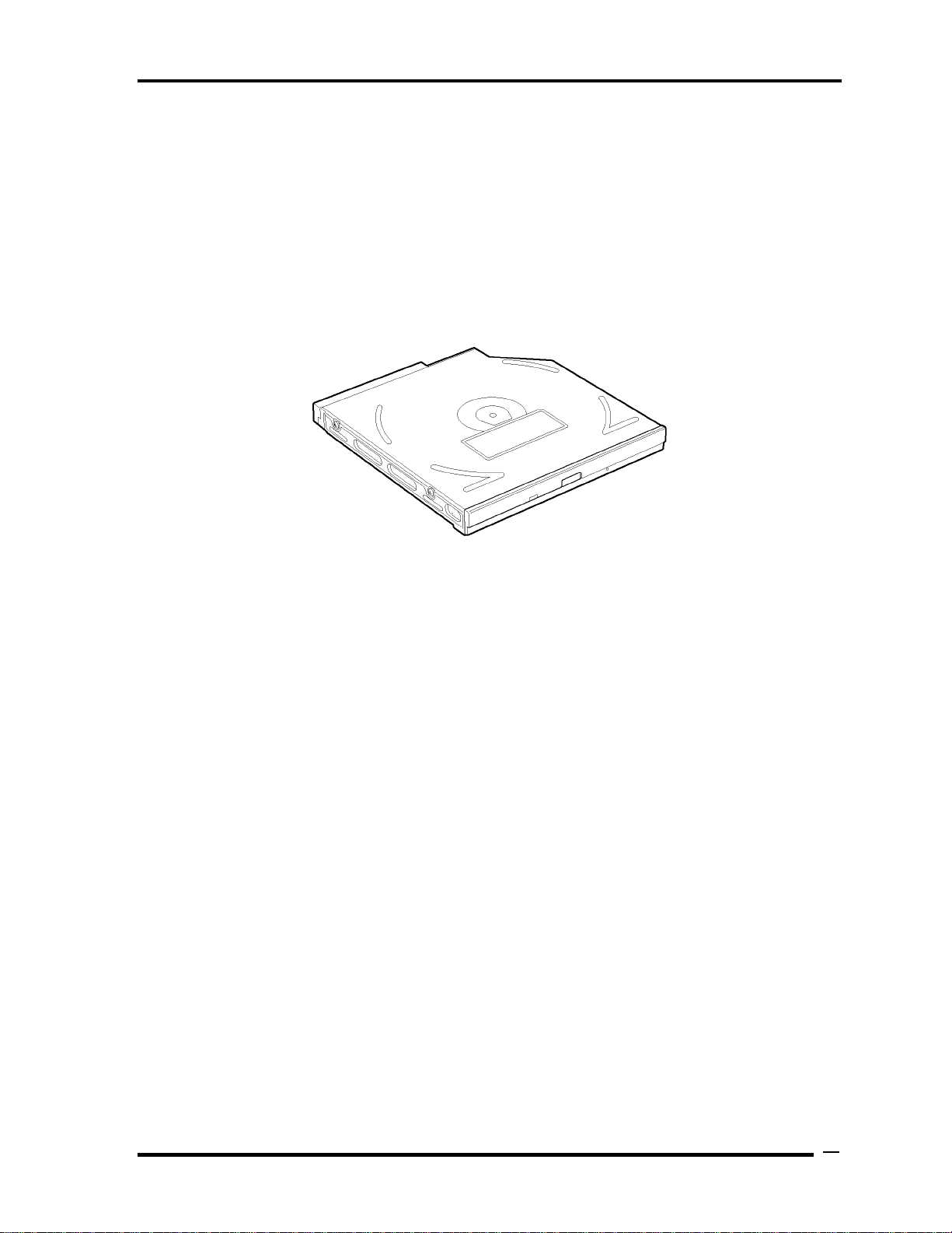
1.4 Optical Drive (HD DVD-ROM & CD-R/RW Drive)
The DVD Super Multi drive accommodates either 12 cm (4.72-inch) or 8 cm (3.15-inch)
CD/DVD-ROM, CD-R/RW, DVD±R/±RW and DVD-RAM. It is a high-performance drive
that reads DVD-ROM at maximum 8-speed and CD at maximum 24-speed. Write speed of
DVD±R/±RW and DVD-RAM is different depending on the drive.
The DVD Super Multi drive is shown in Figure 1-4-1. The dimensions and specifications of
the DVD Super Multi drive are described in Table 1-4-2, Table 1-4-3, Table 1-4-4, Table 1-
4-5.
Figure 1-4-1 DVD Super Multi drive
11
Qosmio X500
Maintenance Manual (960-Q08)
Chapter 1 Hardware Overview
Table 1-
4-2
DVD Super Multi drive outline dimensions
Parameter Standard value
Maker
HLDS
(GT20N-ATAK7N7 )
HLDS
(GT20F-ATAK7N7)
Width (mm) 128
Height (mm) 12.7
Depth (mm) 127
Outline
dimensions
Mass (g) 168
Parameter Standard value
Maker
Panasonic
(UJ240/J890ADTJR-A)
Panasonic
(UJ141/UJ890EDTJR-A)
Width (mm) 128
Height (mm) 12.7
Depth (mm) 129
Outline
dimensions
Mass (g) 185
Parameter Standard value
Maker
TSST
(TS-L633C)
TSST
(TS-L633Y)
Width (mm) 128
Height (mm) 12.7
Depth (mm) 127
Outline
dimensions
Mass (g) 165
Qosmio X500
Maintenance Manual (960-Q08)
12
Chapter 1 Hardware Overview
Qosmio X500
Maintenance Manual (960-Q08)
13
Table 1-
4-3
HLDS DVD Super Multi drive specifications
HLDS Drive Specification
Parameter
GT20N-ATAK7N7 GT20F-ATAK7N7
Label Flash Function
No support Support
Read
DVD-ROM 8x max.
DVD-R(SL/DL) 8x/4x max.
DVD+R(SL/DL) 8x/4x max.
DVD-RW 8x max.
DVD+RW 8x max.
DVD-RAM (Ver.1.0) 2x
(Ver.2.2) 2x, 3x, 5x
DVD-Video 4x max. (Single/Dual layer)
CD-R/RW/ROM 24x/24x/24x max.
CD-DA (DAE: Ripping/Play) 20x/20x max.
Write
DVD-R 2x CLV, 4x ZCLV, 8x CAV
DVD-R DL 2x CLV, 4x ZCLV
DVD-RW 1x, 2x CLV, 4x, 6x ZCLV
DVD-RAM 2x, 3x ZCLV, 5x PCAV(Ver.2.2)
(16x Media: Not support)
DVD+R 2.4x CLV, 4x ZCLV, 8x CAV
DVD+R DL 2.4x CLV, 4x ZCLV
DVD+RW .4x, 3.3x CLV, 4x ZCLV, 8x ZCLV
(8x Speed disc: 3.3x CLV, 8x ZCLV)
CD-R 10x CLV, 16x, 24x ZCLV
CD-RW 4x, 10x CLV, 16x ZCLV
Data transfer
speed
Burst
Transfer
mode
PIO mode4/Multi word mode2/Ultra DMA mode2
CD-ROM 130ms (Typ.)
Access time
(ms) (Random)
DVD-ROM 135ms (Typ.)
Buffer memory 2MB
Chapter 1 Hardware Overview
Qosmio X500
Maintenance Manual (960-Q08)
14
Table 1-
4-4
Panasonic DVD Super Multi drive specifications
Panasonic Drive Specification
Parameter
UJ240/UJ890ADTJR-A UJ141/UJ890EDTJR-A
Label Flash Function
No support Support
Read
DVD-ROM :Max 8X CAV
CD-ROM :Max 24X CAV
Write
CD-R :Max24X CAV
CD-RW :4X CLV
High Speed CD-RW :10XCLV
Ultra Speed CD-RW :Max 16X Zone CLV
DVD-R :Max.8X CAV
DVD-R DL :Max.4X Zone CLV
DVD-RW :Max.6X Zone CLV
DVD+R :Max.8X CAV
DVD+R DL :Max.4X Zone CLV
DVD+RW :Max.8X Zone CLV
DVD-RAM :3-5X ZCLV ( 4.7GB)
Data transfer
speed
Burst Transfer
mode
PIO mode4/Multi word mode2/Ultra DMA mode2
CD-ROM 150ms (Typ.)
Access time
(ms) (Random)
DVD-ROM 180ms (Typ.)
Buffer memory 2MB
Loading...