


Q-Flowsaver II
Table of contents
 Loading...
TOSHIBA
DIGITAL TRANSISTOR INVERTER
LOW ACOUSTICAL NOISE SERIES
o-nomavEn n
OPERATION MANUAL
October, 1995
Part #36933-000
dì) #

NOTE
The instructions contained in this manual are not intended to cover all of the
details or variations in equipment, nor to provide for every possible contingency
to be met in connection with installation, operation, or maintenance. Should further
information be desired or should particular problems arise which are not covered
sufficiently for the purchaser's purposes, the matter should be referred to the local
Toshiba sales office.
The contents of this instruction manual shall not become a part of or modify any
prior or existing agreement, commitment, or relationship. The sales contract
contains the entire obligation of Toshiba International Corporation's Inverter
Division. The warranty contained in the contract between the parties is the sole
warranty of Toshiba International Corporation's Inverter Division and any
statements contained herein do not create new warranties or modify the existing
warranty.
Any electrical or mechnical modification to this equipment,
without prior written consent of Toshiba International
Corporation, will void all warranties and may void UL listing
and/or CSA certification.
TOSHIBA
AC ADJUSTABLE SPEED DRIVE
Please complete the Extended Warranty Card supplied with this inverter and return
it by prepaid mail to Toshiba. This activates the extended warranty. If additional
information or technical assistance is required call Toshiba's marketing department
toll free at (800) 231-1412 or write to: Toshiba International Corporation, 13131 W.
Little York Road, Houston, TX 77041-9990.
Please complete the following information for your records and to remain within this
equipment manual:
Model Number:
Serial Number:
Date of Installation:
Inspected By:
Reference Number:

TOSHIBA
INTRODUCTION
Thank you for purchasing the Q-FLOWSAVER II. This adjustable frequency solid state AC drive features
low acoustical noise, pulse width modulation, digital control, and user programmability. The very latest
microprocessor and insulated gate bipolar transistor technology is used. This, combined with Toshiba's
high performance software, gives unparalleled motor control and reliability.
It is the intent of this operation manual to provide a guide for safe/y installing, operating, and maintaining
the drive. This operation manual contains a section of general safety instructions and is marked
throughout with warning symbols. Read this operation manua/thoroughly before installation and opera
tion of this electrical equipment.
All safety warnings must be followed to ensure personal safety.
Follow all precautions to attain proper equipment performance and longevity.
The manual is divided into major sections of interest. All of the initial inspection, storage, installation and
operating precautions can be found in Sections 1 and 2 with Section 3 and 4 containing all of the
standard specifications and information on grounding, wiring, and cable sizes.
Section 5 contains information about the printed circuit board layouts, connectors, wiring jumpers, and
connector functions.
Section 6 shows layout information about the keypad panel and readouts.
Sections 7, 8, 9, 10, and 11 are devoted to the functional parameter groups, functional parameter
access and operation, status monitoring, and input and output terminal functions.
Section 12 contains a major component list with recommended spare parts along with a problem sheet
showing the necessary information for after sales service.
Section 13 contains shipping weights, dimensional data, component layouts, and schematics.
We hope that you find this operation manual informative and easy to use. If additional information or
technical assistance is needed, please call toll free (800) 231-1412 or write to: Toshiba International
Corporation, 13131 W. Little York Road, Houston, TX 77041-9990.
Again thank you for the purchase of this product.
TOSHIBA INTERNATIONAL CORPORATION

GENERAL SAFETY INSTRUCTIONS
Warnings in this manual appear in either of two ways:
1) Danger warnings - The danger warning symbol is an exclamation mark enclosed in a
triangle which precedes the 3/16" high letters spelling the word "DANGER". The
Danger warning symbol is used to indicate situations, locations, and conditions that
can cause serious injury or death:
!\ DANGER
2) Caution warnings - The caution warning symbol is an exclamation mark enclosed in a
triangle which precedes the 3/16" high letters spelling the word "CAUTION". The
Caution warning symbol is used to indicate situations and conditions that can cause
operator injury and/or equipment damage:
!\ CAUTION
TOSHIBA
Other warning symbols may appear along with the Danger and Caution symbol and are used to specify
special hazards. These warnings describe particular areas where special care and/or procedures are
required in order to prevent serious injury and possible death:
1) Electricai warnings - The electrical warning symbol is a lighting bolt mark enclosed in
a triangle. The Electrical warning symbol is used to indicate high voltage locations and
conditions that may cause serious injury or death if the proper precautions are not
observed:
A
2) Explosion warnings - The explosion warning symbol is an explosion mark enclosed in
a triangle. The Explosion warning symbol is used to indicate locations and conditions
where molten, exploding parts may cause serious injury or death if the proper
precautions are not observed:
III

TOSHIBA
CONTENTS
SECTION PAGE
Disclaimer ....................................................................................................i
introduction..................................................................................................ii
Generai Safety instructions.........................................................................iii
Contents ...................................................................................................iv-vi
1.0 inspection/Storage/Disposai.....................................................................1-1
1.1 Inspection of the New Unit.............................................................1-1
1.2 Storage
1.3 Disposal.........................................................................................1-1
..........................................................................................
1-1
2.0 Safety in Instaiiation and Operation..........................................................2-1
2.1 Installation Precautions
.................................................................
2-1
2.2 Operating Precautions....................................................................2-2
2.3 Confirmation of Wiring....................................................................2-4
2.4 Start-up and Test............................................................................2-4
3.0 Standard Specifications............................................................................3-1
4.0 Wiring ........................................................................................................4-1
4.1 Simple Connection Diagrams........................................................4-1
4.2 Selection of Main Circuit Wiring Equipment and
Standard Cable Sizes.....................................................................4-3
4.3 Grounding.......................................................................................4-4
5.0 PWB Layout, Jumpers, and Terminai Connections
5.1 Control/Driver Board for 02-2035 through 02-2330
5.2 Control/Driver Board for 02-4055 through 02-4330
5.3 Control Board for 02-4400 through O2-420K
5.4 Driver Board for 02-4400 through Q2-420K
.................................
......................
......................
.................................
...................................
5-1
5-1
5-2
5-3
5-4
5.5 Jumper Details................................................................................5-5
5.6 Control/Driver Board Terminal Block Details
.................................
5-5
5.7 Jumper/Terminal Connections and Functions................................5-6
5.8 Terminal Connections and Functions.............................................5-7
IV

CONTENTS (confd)
TOSHIBA
SECTION
PAGE
6.0 Operating Panel..........................................................................................6-1
6.1 Operating Panel Layout...................................................................6-1
6.2 Operating Panel Keys and Functions
6.3 LED Display and Display Monitoring
..............................................
...............................................
6-1
6-3
6.4 Display Alphanumerics....................................................................6-4
7.0 Parameter Groups.......................................................................................7-1
7.1 Definitions of Setup and Group Parameters....................................7-1
7.2 System Parameters Adjustment Range and Factory Settings
.......
7-2
8.0 System Status Monitoring........................................................................... 8-1
8.1 Normal Status Monitoring................................................................8-1
8.2 Automatic Status Monitoring............................................................8-2
8.3 Tripped Status Monitoring
...............................................................
8-3
8.4 Input Terminal Status Code.............................................................8-4
8.5 Output Terminal Status Code..........................................................8-5
9.0 Keypad Operating Functions
......................................................................
9-1
9.1 Setup Parameters............................................................................9-1
9.2 User Group Parameters
.................................................................
9-3
9.3 Communication Group Parameters.................................................9-5
9.4 Jump Frequency Group Parameters
...............................................
9-7
9.5 Display Group Parameters..............................................................9-8
9.6 Speed Group Parameters................................................................9-9
9.7 Pattern Frequency Group Parameters
...........................................
9-10
9.8 Emergency Stop.............................................................................9-12
10.0 Input Terminal Operating Functions..........................................................10-1
10.1 Input Terminal Selection Function
.................................................
10-1
10.2 Starting/Stopping-Remote Control................................................ 10-2
10.3 Emergency Stop From a Remote Location...................................10-2
10.4 Remote Control Frequency Setting................................................10-2
10.5 Jog ................................................................................................. 10-3
10.6 Resetting After a Trip......................................................................10-3
10.7 Pattern Run.................................................................................... 10-4
10.8 PID Set Point Control
.....................................................................
10-5

TOSHIBA
CONTENTS (cont'd)
SECTION PAGE
11.0 Output Terminal Operating Functions
11.1 Selectable Outputs
.......................................................................
11.2 Inverter to Relay/PC Connections
.........................................................
...............................................
11.3 Fault Detection Output Terminals................................................ 11-2
11.4 Calibration of Remote Meters...................................................... 11-3
12.0 Spare Parts List/After Saies Service
.......................................................
12.1 Requesting After Sales Service................................................... 12-1
12.2 Recommended Spare Parts......................................................... 12-2
12.3 Parts Service Life......................................................................... 12-5
13.0 Dimensions/Weights/Component Layouts/Schematics
13.1 Basic Dimensions.........................................................................13-1
13.2 Operating Panel Assembly........................................................... 13-3
13.3 Shipping Weights
..........................................................................
13.4 Component Layouts......................................................................13-5
13.5 Schematics...................................................................................13-14
..............................
11-1
11-1
11-2
12-1
13-1
13-4
VI

1.0 Inspection/Storage
1.1 Inspection of the New Unit
Upon receipt of the Q-FLOWSAVER II, a careful inspection for shipping damage should
be made. After uncrating:
1) Check the unit for loose, broken, bent or otherwise damaged parts due to
shipping.
2) Check to see that the rated capacity and the model number specified on the
nameplate conform to the order specifications.
1.2 Storage
1) Store in a well ventilated location and preferably in the in the original carton if
the inverter will not be used immediately after purchase.
2) Avoid storage in locations with extreme temperatures, high humidity, dust, or
metal particles.
1.3 Disposal
Please contact your state environmental agency for details on disposal of electrical
components and packaging in your particular area.
TOSHIBA
1 - 1

TOSHIBA
2.0 Safety in Installation and Operation
2.1 Installation Precautions /!\ CAUTION
2)
3)
4)
5)
6)
7)
8)
1)
Install in a secure and upright position in a well ventilated location where the
ambient temperature is between -10 deg C and 40 deg C (up to 50 deg C when
not enclosed in a cabinet). Do not allow direct sunlight to shine on the unit or
obstruct ventilating openings.
Allow a clearance space of 4 inches (10 cm) for the top and bottom and
2 inches (5 cm) on both sides. This space will insure adequate ventilation.
Avoid installation in areas where vibration, heat, humidity, dust, steel particles,
or sources of electrical noise are present.
Adequate working space should be provided for adjustment, inspection and
maintenance.
Adequate lighting should be available for troubleshooting and maintenance.
A noncombustible insulating floor or mat should be provided in the area
immediately surrounding the electrical system where maintenance is required.
Use separate metal conduits for routing the input power, output power,
and control circuits.
Always ground the unit to prevent electrical shock and to help reduce
electrical noise. A separate ground cable should be run inside of the
A
the conduit is not an acceptable ground.
conduit with the input, output, and control power cables. The metal of
9)
10)
11)
12)
13)
Connect three phase power of the correct voltage to input terminals LI, L2, L3
(R, S, T) and connect three phase power from output terminals T1, T2, T3
(U, V, W) to a motor of the correct voltage and type for the application. Size
the conductors in accordance with Article 310 of the National Electrical Code.
If conductors of a smaller than recommended size are used in parallel to share
current then the conductors should be kept together in as sets i.e. U1, VI, W1
in one conduit and U2, V2, W2 in another. National and local electrical codes
should be checked for possible cable derating factors if more than three power
conductors are run in the same conduit.
Install a molded case circuit breaker (MCCB) between the power source and the
inverter. Size the MCCB to clear the available fault current of the power source.
Installation of inverter systems should conform to the National Electrical Code,
regulations of the Occupational Safety and Health Administration, all national
codes, and all regional or industry codes and standards.
If a secondary Magnetic Contactor (MC) is used between the inverter output
and the load, it should be interlocked so the ST-CC terminals are disconnected
before the output contactor is opened. If the output contactor is used for bypass
operation, it must also be interlocked so that commercial power is never applied
to the inverter output terminals (U,V,W).
2 -1
2.2 Operating Precautions /!\ CAUTION
TOSHIBA
2)
3)
4)
5)
6)
1)
Do not apply power and attempt to use the inverter until this entire operation
manual has been carefully reviewed.
The input voltage must be within +/-10% of the specified input voltage. Voltages
outside of this permissible tolerance range may cause internal protection
devices to turn on or can cause damage to the unit. Also, the input frequency
should be within +1-2 Hz of the specified input frequency.
Do not use this inverter with a motor whose rated input is greater than the rated
inverter output.
This inverter is designed to operate NEMA B motors. Consult the factory before
using the inverter for special applications such as an explosion proof motor or
one with a repetitive type piston load.
Kdanger/^
remove the source power and check that the charge and power LED's are out.
Do not touch any internal part with
power applied to the inverter. First
A hazard exists temporarily for electrical shock even if the source power
Is removed.
Do not apply commercial power to the output terminals T1 (U), T2 (V), or T3 (W)
even if the inverter source power is off. Disconnect the inverter from the motor
before applying a test or bypass voltage to the motor.
7)
8)
9)
10) Interface problems can occur when this inverter is used in conjunction with
Use caution when setting output frequency. Overspeeding of the motor can
cause serious damage to the motor and/or the driven load equipment.
Use caution when setting the acceleration and/or deceleration time.
Unnecessarily short acc/dec time can cause undue stress and tripping of the
drive.
some types of process controllers. Signal isolation may be required to
Do not operate this unit with the cabinet door open.
prevent controller and/or inverter damage.
Contact Toshiba or the process controller manufacturer for further
information about compatibility and signal isolation.
11) When operating the inverter in the PWM high carrier frequency mode (those
frequencies above 12 kHz), the electronic thermal protection /eve/function
parameter [:tHr] should be changed from the factory setting of 100% to 90%
(see Setup Parameters ITEM 9 page 7-2). This is to compensate for the 10%
derating factor required at 16 kHz operation. Follow the general procedures for
changing function parameters. Further derating may be required for cable runs
of greater than 100 feet. Contact Toshiba for more information.
12) Personnel who have access to the adjustments and operation of this equipment
should be familiar with these drive operating instructions and with the machinery
being driven.
2-2

TOSHIBA
2.2 Operating Precautions (cont'd) /!\ CAUTION
2.3 Confirmation of Wiring /!\ CAUTION
13) Do not open and then re-close a secondary magnetic contactor (MC) between
the inverter and the load until the Inverter has been turned OFF (output frequency
has dropped to zero) and the motor has stopped rotating. Abrupt re-application
of the load while inverter is ON or motor is rotating can cause inverter
damage.
14) The operator of the drive equipment should be properly trained In the operation
of the equipment.
15) Follow all warnings and precautions; do not exceed equipment ratings.
Make the following final checks before applying power to the unit:
1)
2)
3)
4)
Confirm that source power is connected to terminals LI, L2, L3 (R, S, T).
Connection of incoming source power to any other terminals will damage
the inverter.
The 3-phase source power should be within the correct voltage and frequency
tolerances.
The motor leads must be connected to terminals T1, T2, T3 (U, V, W).
Make sure there are no short circuits or inadvertent grounds and tighten any
loose connector terminal screws.
2.4 Start-Up and Test /!\ CAUTION
Prior to releasing an electrical drive system for regular operation after installation,
the system should be given a start-up test by competent personnel. This assures
correct operation of the equipment for reasons of reliable and safe performance. It is
important to make arrangements for such a check and that time is allowed for It.
When power Is applied for the first time the inverter will come up in the factory settings
(See section 7.2). If these settings are incorrect for the application trial run then the
correct settings should be programmed from the control panel before activating the run
button. The inverter can be operated with no motor connected. Operation with no
motor connected or use with a small trial motor Is recommended for initial adjustment or
for learning to adjust and operate the inverter.
2.5 Maintenance A CAUTION
1)
2)
3)
Periodically check the operating inverter for cleanliness.
Keep the heatsink free of dust and debris.
Periodically check electrical connections for tightness
A
power is off and locked out).
2-3
(make sure
3.0 Standard Specifications
TOSHIBA
RATINGS
MODEL RATED
KVA
*02-2035 3.5 9.6
*02-2055 5.5
*02-2080 8
*02-2110
*02-2160 16
*02-2220
*02-2270
*02-2330 33
*02-4055 5.5 7.6
*02-4080 8
*02-4110
*02-4160 16
*02-4220
*02-4270
*02-4330 33 40
*02-4400 40 55
*02-4500 50 65
*02-4600 60
*02-4800 80
*02-41 OK
**02-412K
**02-415K
**Q2-420K
11
22
27
11
22
27
100
125
150
200 240
OUTPUT
CURRENT
AMPS
15.2 3-PHASE
14.5
28.5
36.5
104
124
162
194
OUTPUT
VOLTAGE
3-PHASE
200-230V
22 (MAX
28
42 VOLTAGE
56
68
84
11 3-PHASE 400-460V@60Hz
21 OUTPUT Hz +/-2HZ
84
OUTPUT
UNDER NO
LOAD)
380-460V 380V@50Hz or
(MAX
VOLTAGE
UNDER NO
LOAD)
OVERLOAD
CURRENT
120% FOR
60 SEC.
110% VOLT ±10%
CONTINUOUS
MAIN CIRCUIT
INPUT VOLTAGE
200V@50Hz or NO EXTERNAL
200-230V@60Hz CONTROL
VOLT+/-10%
3-PHASE
Hz ±2Hz REQUIRED
CONTROL
CIRCUIT
SINGLE PHASE
SOURCE
This unit is UL (Underwriters Laboratories Inc.'
Association) certified.
This unit is UL (Underwriters Laboratories Inc.) listed and CUL (Canadian Underwriters
Laboratories Inc.) listed.
listed and CSA (Canadian Standards
3-1
TOSHIBA
3.0 Standard Specifications (cont'd)
ITEM STANDARD SPECIFICATIONS
Control Control Method Sinusoidal PWM control
Output voltage regulation Same as power line.
Output frequency 0.0 to 160.0 Hz (0.0 to 60 Hz setting when shipped); maximum
frequencv ranqe is 30 to 160 Hz *1
Operating
functions
Protection
Frequency setting
resolution
Frequency accuracy ±0.5% (at 25°C; ±10°C) aqainst the maximum frequency
Voltage/frequency
characteristics
Frequency setting signals
Output frequency
characteristics of IV
terminal input signal
Frequency jump
Upper/lower limit
frequencies
PWM carrier frequency
switching
Acceleration/deceleration
time
Electrical braking
Forward or reverse run Forward run when F-CC closed; reverse run when R-CC closed;
Jogging run
Multispeed run By opening and closing different combinations of CC, SSI, SS2,
Automatic fault latch reset When a protective function is activated, the system checks main
Soft stall Sustains a run in overload mode (set at ON when shipped)
Automatic restart
Programmable RUN
patterns
Protective functions Stall prevention, current limit, overcurrent, overvoltage, short-
Electronic thermal
characteristics
Reset Resets inverter when N.O. contact is closed.
0.1Hz: Operating panel input; 0.03 Hz: Analog input; 0.01Hz:
Input throuqh computer interface (aqainst a 60 Hz)
Second-order nonlinear mode for variable torque.
"Max voltage" frequency adjustment (25 to 160 Hz), torque
boost adjustment (0 to 30 %), start-up frequency adjustment
(Oto 10 Hz)
3k ohms potentiometer (a 1 k to 10k ohms-rated potentiometer can
be connected). 0 to 10 Vdc (input impedance: 30k ohms), 0 to
5 Vdc (15k ohms), 4 to 20 mAdc (250 ohms)
Can be set to an arbitrary characteristic by setting 2 points.
3-point setting; setting jump frequency and band width
Upper limit frequency: 0.0 Hz to maximum frequency
Lower limit frequency: 0.0 Hz to upper limit frequency
Adjusted in the range of 5 kHz to 16 kHz (12 kHz setting when
shipped)
0.1 to 1200 seconds, switching of acceleration time 1 or 2,
selection of S-shaped 1 or 2, or selection of acceleration/
deceleration patterns
DC injection braking
reverse run when both F-CC and R-CC closed; coasting stop
when ST-CC open; emergency coast stop by a command from
operating panel
Jogging run engaged when N.O. contact is closed, (adjustment
range 0.0 to 20.0 Hz)
and SS3, the set speed or seven preset speeds can be selected.
circuit devices, and attempts the restart up to 5 times (activated
when shipped)
Smoothly recovers a normal run of a free-running motor utilizing
motor speed detection control.
Allows setting of 7 different patterns of automatic operation
circuit at load, load-end ground fault, undervoltage, momentary
power interrupt, electronic thermal overload, main circuit over
current at start-up, load-end overcurrent at start-up, cooling
fin overheat, and emergency stop. Provisions for external
fault signal.
Standard motor/constant torque V/f motor switching, and
electronic thermal stall prevention activating level adjustment
Start-up frequency adjustment (0 to 10 Hz),
braking voltage adjustment (0 to 20 %),
braking time adjustment (0 to 5 seconds)
Consult the factory for applications above 80 Hz.
3-2
3.0 Standard Specifications (cont'd)
ITEM STANDARD SPECIFICATIONS
Display (4) 7-segment red LED
digits with colon and
decimal points
(4) discrete green LED's
(1) discrete red LED
(located inside enclosure)
Output signals Fault detection signal One form C contact (250 AC / 30 Vdc)
Low speed/reach signals Open collector output (24 Vdc, 50 mA maximum)
Upper limit/lower limit
frequency signals
Frequency meter output
and ammeter output
Enclosure type NEMAType 1 (standard)
Cooling method
Color Sherwin Williams Precision Tan #F63H12
Service
conditions
Service environment Indoor, altitude 1000m (3,300 ft) maximum. Must not be exposed
Ambient temperature From -10 to 40°C (contact Toshiba about operation above 40°C)
Relative humidity
Vibration
Output
frequency/
OFF
Warning
indications
Fault
indications
Data and
status
Speed
scaling
Data
storage
DC charge
indicator
Open collector output (24 Vdc, 50 mA maximum)
Ammeter rated at 1 mAdc at full scale, or voltmeter rated at
7.5 Vdc, 1 mA
Convection-cooled 02-2035 and 02-4055
Fan-cooled 02-2055 thru 02-2330 and 02-4080 thru Q2-420K
to direct sunlight, or subjected to corrosive or explosive gas
or mists.
95 % maximum (no condensation allowed)
Acceleration at 0.5 G maximum (20 to 50 Hz), amplitude at
0.1 mm maximum (50 to 100 Hz)
Frequency range 0.0 to 160 Hz and OFF state
Stall preventive warning, overvoltage limit
warning, overload warning, power-end undervoltage
warning, DC main circuit undervoltage warning,
setting errors, EEPROM abnormality, and data
transfer abnormality warnings
Overcurrent, overvoltage, load-end ground fault,
overload, armature overcurrent at start-up, load-end
overcurrent at start-up, heat sink overheat.
Inverter status (forward/reverse run, frequency set
value, output current, etc.) and each set value
An arbitrary unit (revolution speed, linear velocity or
the like) as well as output frequency can be displayed
by use of an arbitrary multiplication factor
A number is assigned to each inverter (for 0 to 31
inverters).
Main DC bus circuit capacitors charge indicator
TOSHIBA
3-3
TOSHIBA
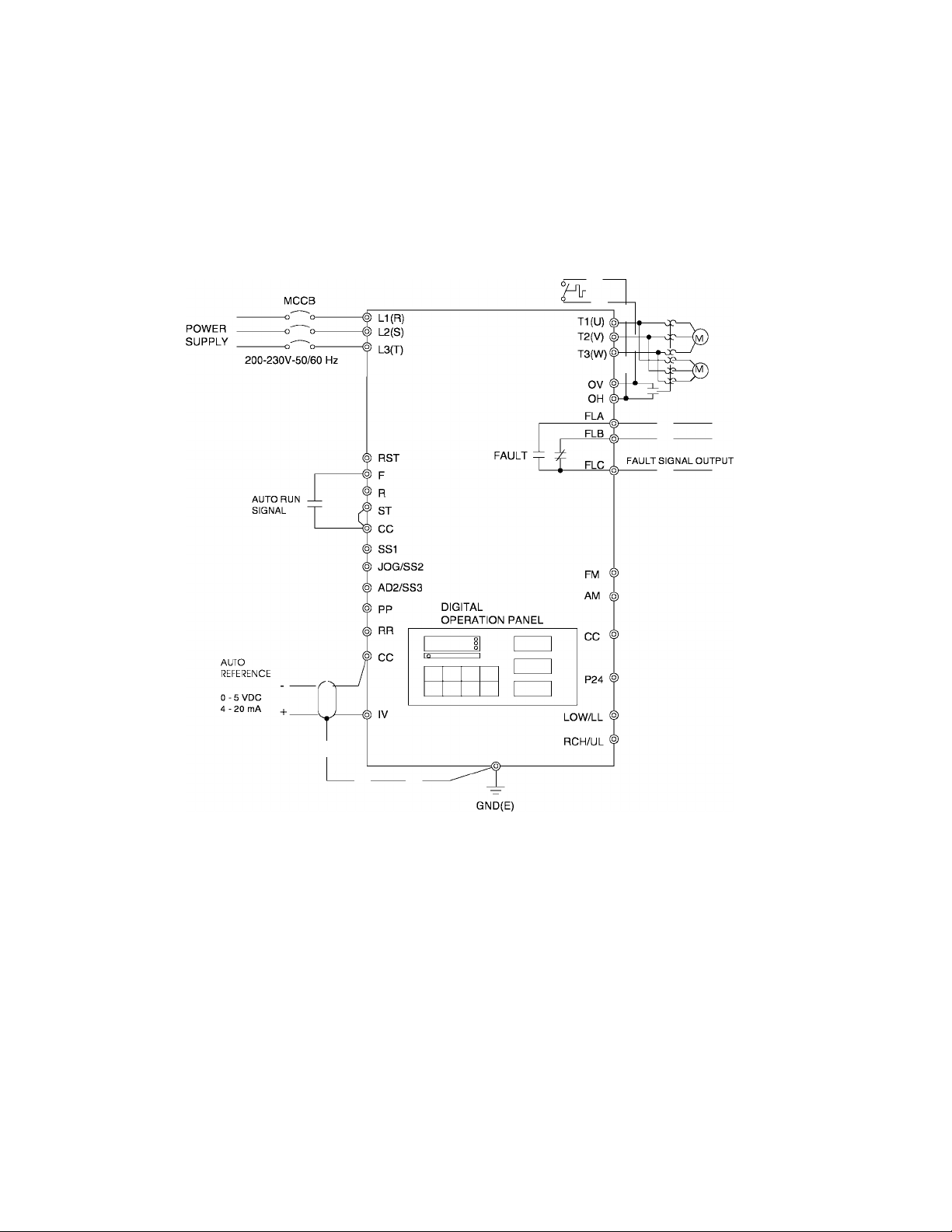
4.0 Wiring
4.1 Simple Connection Diagrams
Q-FLOWSAVER II
STANDARD CONNECTION
MODEL 2035 TO 2330
Notes:
1) For control/driver terminal block layout see Page 5-5.
2) For recommended wire sizes see Page 4-3.
3) For terminal connections and functions see Page 5-6 through 5-8.
4) Contact Toshiba when interfacing with a process controller.
4 -1
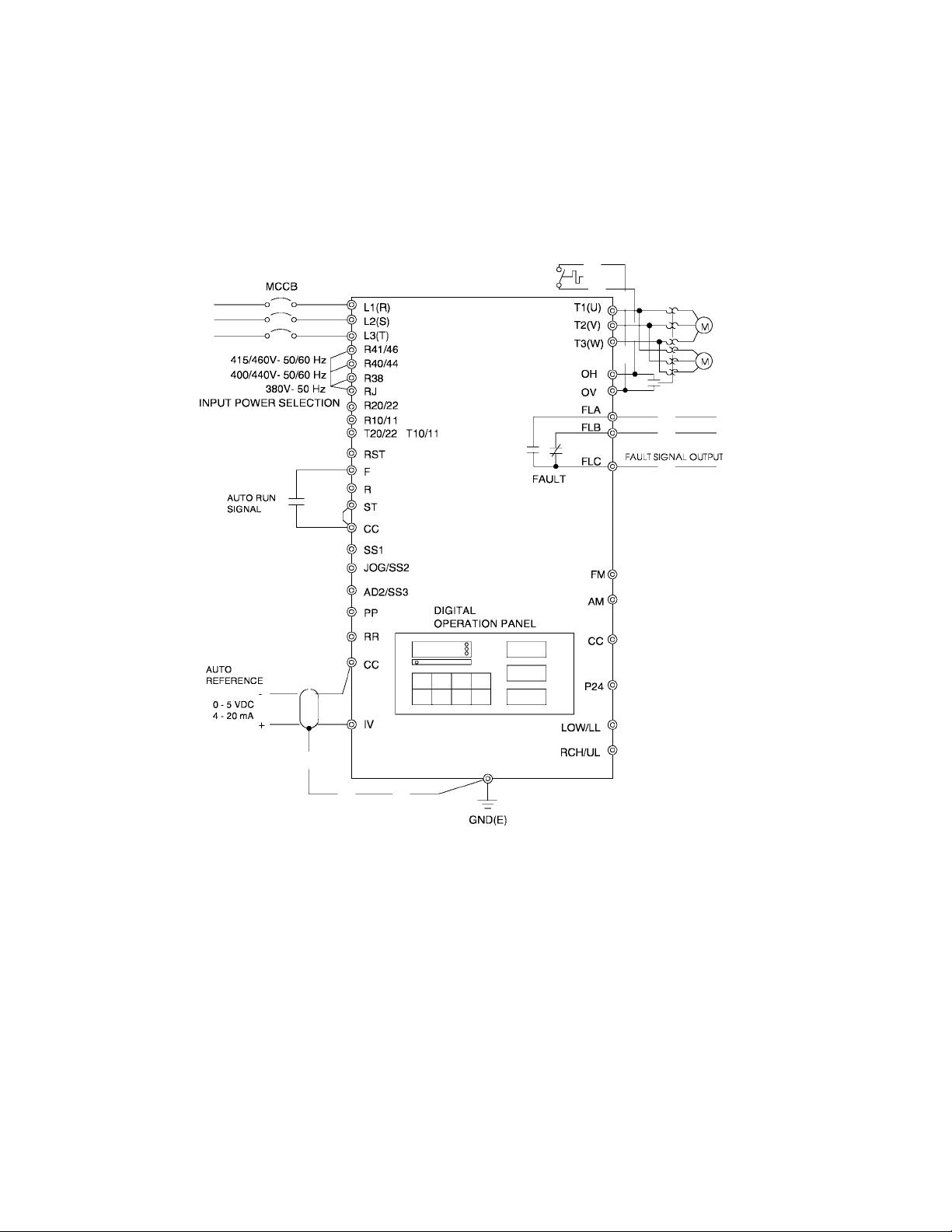
4.1 Simple Connection Diagrams (cont'd)
Q-FLOWSAVER II
STANDARD CONNECTION
MODEL 4055 TO 420K
POWER
SUPPLY
TOSHIBA
Notes:
1) For control/driver terminal block layout see Page 5-5.
2) For recommended wire sizes see Page 4-3.
3) For terminal connections and functions see Page 5-6 through 5-8.
4) Contact Toshiba when interfacing with a process controller.
4-2

TOSHIBA
4.2 Selection of Main Circuit Wiring Equipment and Standard Cable Sizes
Inverter
Type form
•Molded case
circuit breaker
(MCCB)
Amp
rating
(A)
Q2-2035 20 13.8
Q2-2055 30 21.9
Q2-2080 50 31.6 #10
Q2-2110 70 40 #8
Q2-2160 90 60 #6
Q2-2220 100 78
Q2-2270 125 98 #3
Q2-2330 150 115
Q2-4055 15 10.9
Q2-4080 30 15.8
Q2-4110 30 20.1
Q2-4160 40
Q2-4220 50 38.8 #8
Ampacity
(FLA X 1.25) •'Typical cable size (AWG)
Main power
(A)
motor load
30.2
and
#14
#12
#4
#2
#14
#14
#12 #14
#10
230Vac and
460Vac control
power source
Frequency
command input,
frequency meter,
ammeter
3-core shield cable
(speed reference)
2-core shield cable
#20
Other
signal
circuits
#18
Q2-4270 70 48.8 #8
Q2-4330 90 57.5 #6
Q2-4400 100 74.8
Q2-4500 100
Q2-4600 125
Q2-4800 175 138 #1/0
Q2-410K
Q2-412K
Q2-415K
Q2-420K
200 178.3 #3/0
225 223 #4/0
300 268 ••• 2(#2/0)
350 330 ••• 2(#4/0)
93.4
110.7 #2
See next page for notes and precautions.
#4
#3
4-3

4.2 Selection of Main Circuit Wiring Equipment and Standard Cable Sizes (cont'd)
* The customer supplied Molded Case Circuit Breaker (MCCB) or Magnetic Circuit
Protector (MCP) should be coordinated with the available short circuit current. The units
are rated for output short circuit faults of 5000A (1 - 50 HP), lO.OOOA (51 - 200 HP), and
18,000A (201 - 400 HP) according to the UL 508C "Power Conversion Equipment",
Table 58.2 or CSA Standard C22.2 No.14-M1987 "Industrial Control Equipment"
Table 24. The selection of breakers for this table is in accordance with 1990 NEC
Article 430. The selection of these breakers takes into consideration motor starting
at the low end of the output voltage specifications but does not consider the use of
high efficiency motors.
* For multiple motor applications, the magnetic only MCP should be replaced by a thermal
magnetic MCCB. The MCCB should be sized according to 1.25 X (largest motor Full
Load Amps) + (sum of all other motor Full Load Amps) to meet National Electric Code
(NEC) or Canadian Electrical Code (CEC) requirements. An individual overload relay
must be provided for each motor in multiple motor applications.
** Wire sizing is based upon NEC table 310-16 or CEC Table 2 using 75 deg C cable, an
ambient of 30deg C, cable runs for less than 200 FT., and copper wiring for not more
than three conductors in raceway or cable or earth (directly buried). The customer should
consult the NEC or CEC wire Tables for his own particular application and wire sizing.
TOSHIBA
** For cable runs greater than 200 FT. between the motor and inverter, consult the factory
before installing.
*** Use two parallel conductors instead of a single conductor (this will allow for the proper
wire bending radius within the cabinet). Use separate conduits for routing parallel
conductors. This prevents the need for conductor derating (see note 3 this page).
Use separate conduits for routing incoming power, power
CAUTION to motor, and control conductors. Use no more than three
K
Notes:
1. ) Auxiliary relays used to switch inverter signals should be capable of switching
low current signals (i.e. 5mA).
2. ) The inverter has internal overload protection, but the Local, National, or
Canadian Electrical Codes may require external motor overload protection.
3. ) When wiring with parallel conductors, the conductors should be kept together in
phase sets with U1, VI, W1 in one conduit and parallel conductors U2, V2, W2
in another conduit. The ground conductor should be in one of these conduits.
4) Twisted pair wiring should be used for external meters connected to AM and FM
terminals.
power conductors and a ground conductor per conduit.
4.3 Grounding
The inverter should be grounded in accordance with Article 250 of the National Electrical
Code or Section 10 of the Canadian Electrical Code, Part I and the grounding conductor
should be sized in accordance with NEC Table 250-95 or CEC, Part I Table 16.
!\ CAUTION Conduit is not a suitable ground for the inverter.
4-4
TOSHIBA
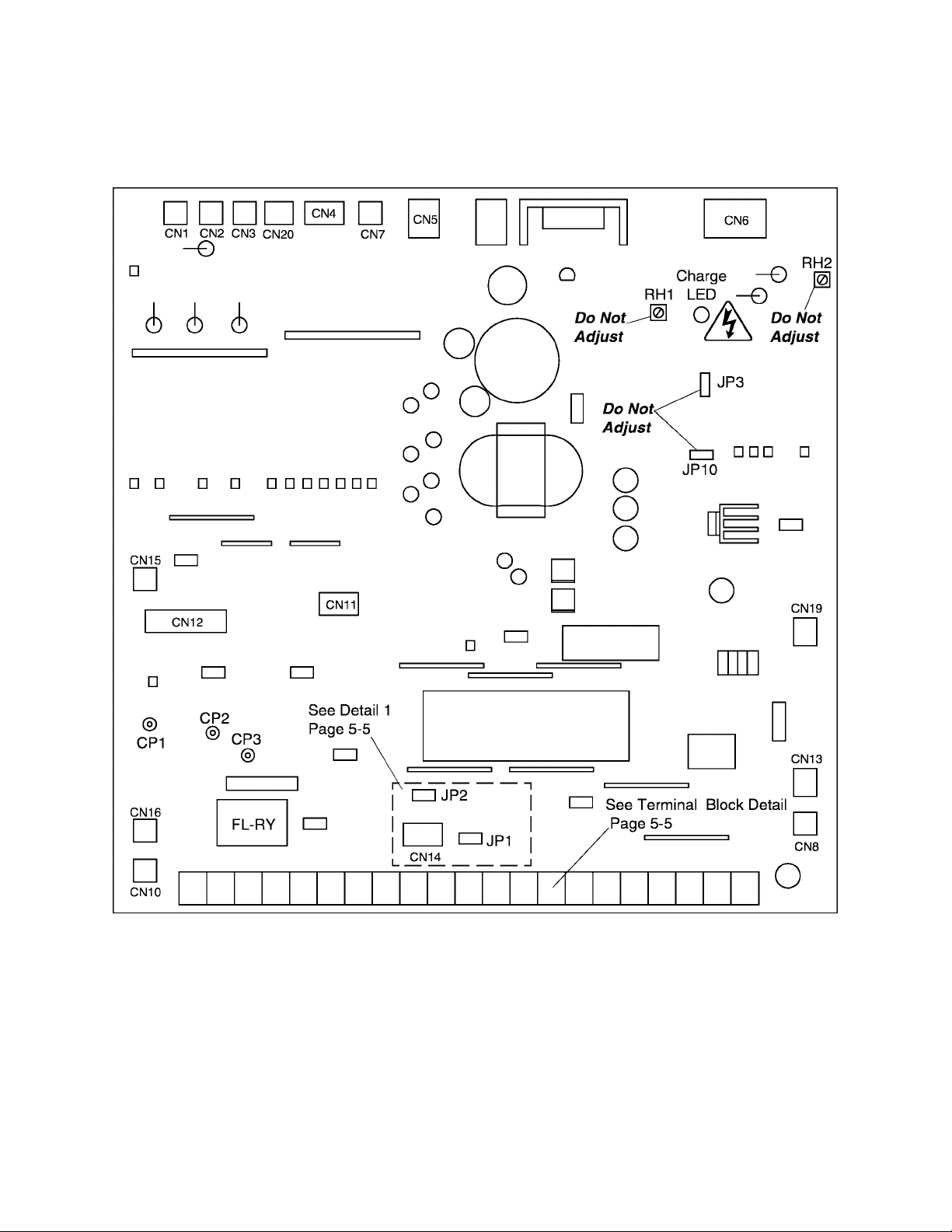
5.0 PWB Layout, Jumpers, and Terminal Connections
5.1 Control/Driver Board for Q2-2035 through Q2-2330
The following pictorial shows a layout of the major components located on the
control/dhver board VF3B-0100.
Note:
1) Potentiometer RH1 is used for control power supply stabilization. This adjustment is
factory set and any ADJUSTMENT BY THE USER SHOULD NOT BE ATTEMPTED.
2) Potentiometer RH2 is used for voltage detection level bias. This adjustment is factory
set and any ADJUSTMENT BY THE USER SHOULD NOT BE ATTEMPTED.
3) CPI, CP2,and CP3 are service testpoints.
4) Do not adjust JP3 and JP10.
5) Charge LED indicates charged capacitors. DO NOT TOUCH internal parts if lighted.
5-1
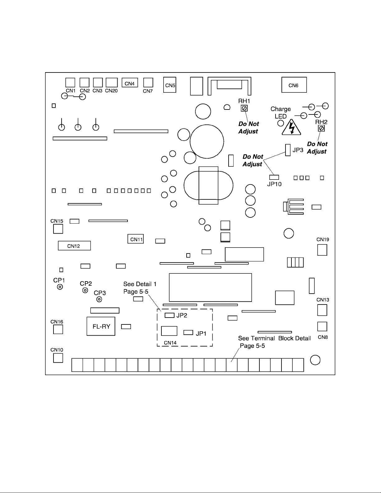
5.2 Control/Driver Board for Q2-4055 through Q2-4330
The following pictorial shows a layout of the major components located on the
control/dhver board VF3B-0101.
TOSHIBA
Note:
1) Potentiometer RH1 is used for control power supply stabilization. This adjustment is
factory set and any ADJUSTMENT BY THE USER SHOULD NOT BE ATTEMPTED.
2) Potentiometer RH2 is used for voltage detection level bias. This adjustment is factory
set and any ADJUSTMENT BY THE USER SHOULD NOT BE ATTEMPTED.
3) CP1, CP2, and CP3 are service testpoints.
4) Do not adjust JP3 and JP10.
5) Charge LED indicates charged capacitors. DO NOT TOUCH internal parts if lighted.
5-2
TOSHIBA
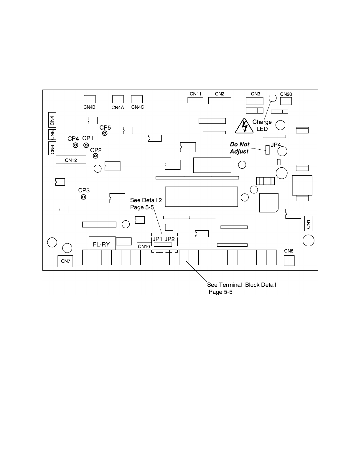
5.3 Control Board for Q2-4400 through Q2-420K
The following pictorial shows a layout of the major components located on the
control board VF3C-1200.
Note:
1) CPI, CP2, CP3, CP4, and CPS are service testpoints.
2) Do not adjust JP4.
3) Charge LED indicates charged capacitors. DO NOT TOUCH internal parts if lighted.
5-3
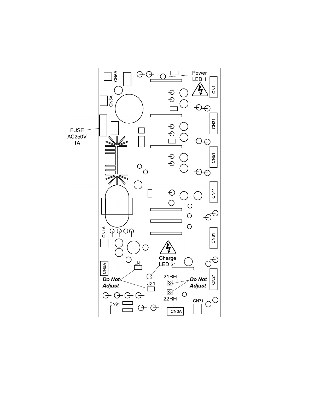
5.4 Driver Board for Q2-4400 through Q2-420K
The following pictorial shows a layout of the major components located on the
driver board 35589.
TOSHIBA
Note:
1) Potentiometer 21RH (OP) is the main circuit overvoltage detection trip set. This
adjustment is factory set and any ADJUSTMENT BY THE USER SHOULD NOT BE
ATTEMPTED.
2) Potentiometer 22RH (MUV) is the main circuit undervoltage detection trip set. This
adjustment is factory set and any ADJUSTMENT BY THE USER SHOULD NOT BE
ATTEMPTED.
3) Do not adjust J4 and J21.
5) Charge LED indicates charged capacitors. DO NOT TOUCH internal parts if lighted.
5-4

TOSHIBA
5.5 Jumper Details
10V 5V
IQ OlO
The jumper connections for each of the printed wiring boards on Pages 5-1 through
5-3 are shown in the enlarged details below. Only jumpers JP1 and JP2 should be
adjusted by the user. See Page 5-6 for jumper adjustments.
JP2
o in ni
Detail 1 (Reference pages 5-1 and 5-2)
1 1
1 1
IV 1 1
1 1
1
I V 10V 5V
lO OlO OlO OI
IP1
Detail 2 (Reference page 5-3)
JP2
Note:
Jumper settings as shown in these illustrations are for reference purposes only and do
not necessarily reflect factory settings nor correct settings for a particular application.
5.6 Control/Driver Board Terminal Block Details
The control/driver board terminal block is shown in detail below. Each of the twenty-one
terminals is functionally labeled. See Pages 5-7 and 5-8 for a list of terminal functions.
Control/Driver Board Terminal Block Detail (Reference pages 5-1,5-2, and 5-3)
© © © © © © © © © © © © © © © © © © © © ©
FLA FLB FLC P24 RCH LOW FM AM PP RR IV CC ST F R CC SSI JOG AD2 RST CC
(UL) (LL) (SS2) (SS3)
5-5
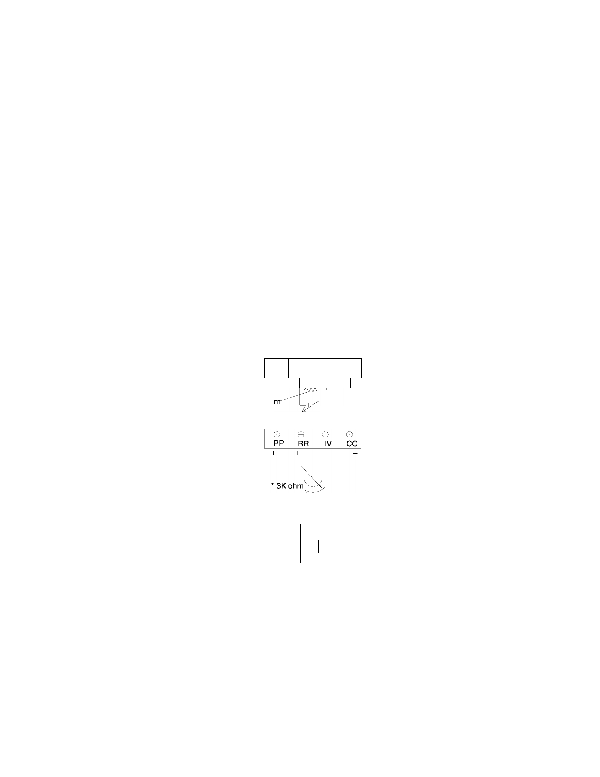
5.7 Jumper/Terminal Connections and Functions
The following table shows how jumpers JP1 and JP2 are set for use with the analog
input terminal connections RR and IV. Jumper numbers and settings which are shown in
this table are applicable to all printed wiring boards (see page 5-5 for terminal block
and jumper details).
Terminal/Jumper Connections for Input Reference Signals
TOSHIBA
JP1
i V
0 olo
I V
N/A
I V
JP2
10V 5V
I 'vJ I 'v.3
N/A
O
N/A
N/A
10V 5V
I 0.") 'vJ I 00
Terminal Connections
No external connections; JP1 and
JP2 should be set as shown for
keypad operation (normal factory
settinoV
_______________________
0
PP
0-20mA
(4-20mA)
PP
0
PP0RR0IV
15Koh
RR IV
RR IV
0-5Vdc
+
CC
0
CC
0
CC
0-1 OVdc
Use when not inputting any external
reference signals into terminal RR or
IV. P.PrG parameter #2 "priority of
RR terminal input" is N/A.
Use when inputting a 4(0)-20mA
external reference signal to terminal IV.
P.PrG parameter #2 "priority of RR
terminal input" should be set to 0 "on".
See page 7-5.
Use when inputting 0-5Vdc external
reference signal to terminal IV.
P.Prg parameter #2 " priority of RR
terminal input" should be set to 0 "on"
See page 7-5.
Use when inputting 0-1 OVdc external
reference signal to terminal RR.
—
P.Prg parameter #2 " priority of RR
terminal input" should be set to 1 "on".
See page 7-5.
Use when inputting 0-1 OVdc external
reference signal to terminal RR.
P.Prg parameter #2 " priority of RR
terminal input" should be set to 1 "on".
See page 7-5.
Function
10V 5V
0 ('<\ ('i
PP
+
o
SW
c
+
•
.
-r0
s.„
0 o
RR IV CC
f
r-
A
---
y'“
0-20mA
(4-20mA)
Use when inputting a 4(0)-20mA
external reference signal to terminal IV
and a 0-1 OVdc reference signal to
terminal RR.
P.PrG parameter #2 "priority of RR
terminal input" should be set to 1 "on".
Terminal RR will override "have priority
over" terminal IV when switch (SW) is
closed.
See page 7-5.
3K ohm pot divides voitage between terminal PP and CC return. Any pot value between 1K to 10K ohms
can be used but makes adjustment more sensitive.
5-6

TOSHIBA
5.8 Terminal Connections and Functions
Terminal
name
LI, L2, L3
(R, S, T)
T1, T2, T3
(U, V, W)
OH
ov
FLA, FLB, FLC
P24
RCH(UL)
Terminal functions Terminal
Input power terminals. Connect to either a 3-phase 50Hz, 200Vac
power supply or to a 3-phase 60Hz, 200 to 230Vac power supply
for models Q2-2035 to Q2-2330.
Input power terminals. Connect to either a 3-phase 50HZ, 380Vac
power supply or to a 3-phase 60HZ, 400 to 460Vac power supply
for models Q2-4055 to Q2-420K.
Output load terminals. Connect these terminals to a 3-phase
induction motor of the proper voltage.
Input terminal for external fault signal.
This is the return terminal for OH.
Output terminals of form C contact changes state when a protective
function has been activated (250Vac - 2A).
Output terminal for unregulated 24Vdc power supply
(100mA maximum output current).
Output terminal (open collector). Provides an output signal ground
(50 mAdc max) when the upper limit frequency is reached, when an
acc/dec is complete, or when the output frequency is within a specified
range. The choice is determined by settings of the Output Terminal
Selection function (:0.tb).
location
Bus bar
or
power
terminal
block
A
Terminal
block
LOW(LL)
FM
AM
PP
RR
IV
CC
(one of three)
Output terminal (open collector). Provides an output signal ground
(50 mAdc max) when a preset low speed or a preset lower limit is
reached. The choice is determined by settings of the Output Terminal
Selection function (:0.tb).
Output terminal for an external analog frequency meter.
Use either an ammeter rated at 1 mAdc at full scale or a voltmeter
rated at 7.5Vdc at full scale.
Output terminal for an external analog ammeter.
Use either an ammeter rated at 1 mAdc at full scale or a voltmeter
rated at 7.5Vdc at full scale.
Regulated 10Vdc power supply to be used with terminal RR for
remote terminal input.
Analog input terminal for a 0 - 5Vdc (JP2 @ 5V) or 0 -10Vdc
(JP2 @ 10V) external reference signal. Also used for wiring a Ik - 10k
ohm (3k ohm recommended) potentiometer to allow for remote speed
control operation.
Analog input terminal for a 0 - 5Vdc (JP1
(JP1 @ I) external reference signal.
This is the common return for PP,RR, and IV terminals.
Do not connect to GND(E).
V) or 4 (0) - 20mAdc
Control
PWB
terminal
block
5-7

5.8 Terminal Connections and Functions (cont'd)
TOSHIBA
Terminal
name
ST
CC
(one of three)
SSI
JOG(SS2)
AD2(SS3)
Terminal functions Terminal
location
Input terminal for run interlock. When ST is shorted to CC, the inverter
is ready to run. With ST-CC open the unit will not run and if opened
while running a coasting stop begins.
Input terminal for forward run. When F is shorted to CC, a forward
run starts. With F-CC open, the unit decelerates to a complete stop.
Input terminal for reverse run. When R is shorted to CC, a reverse run
starts. With R-CC open, the unit decelerates to a complete stop.
If terminals F-CC and R-CC are shorted simultaneously, a reverse
run occurs.
This is the common return for ST terminal.
Do not connect to GND(E).
Input terminal for multi-speed run frequencies. Depends on setting of
function [1 .tb], JOG/SS2 and AD2/SS3 terminals. (See Page 10-1)
Input terminal for jogging run or multi-speed run frequencies. Depends
on setting of function [l.tb], SSI, AD2(SS3) terminals. (See Page 10-1)
Input terminal for multispeed run frequencies. Depends on setting of
function [l.tb], SSI, JOG/SS2 terminals. (See Page 10-1)
Control
PWB
terminal
block
RST
CC
(one of three)
GND(E)
(three provided)
R41/46
R40/44 *
R38
RJ *
R20/22
R10/11 *
With RST-CC shorted, the inverter's protective function resets.
This is the common return for ST, F, R, SSI, JOG(SS2), AD2(SS3),
and RST terminals. S
The inverter earth ground terminal.
o not connect to GND(E).
Do not connect to common return terminal (CC).
Jumper to RJ when using 415V-50Hz/460V-60Hz incoming power.
Do not jumper to R40/44 or R38.
Jumper to RJ when using 400V-50Hz/440V-60Hz incoming power.
Do not jumper to R41/46 or R38.
Jumper to RJ when using 380V-50Hz incoming power.
Do not jumper to R41/46 or R40/44.
Common for input power selection. Jumper to either R41/46, R40/44,
or R38. Do not jumper to more than one terminal at a time.
Output power terminal. Supplies 1-phase 200V-50Hz or 1-phase
220V-60HZ @ 40VA maximum.
Output power terminal. Supplies 1-phase 100V-50Hz or 1-phase
110V-60HZ @ 40VA maximum.
Frame
screw or
lug
Terminal
block
A
T10/11 T20/22
Supplied only on the Q2-4055 through Q2-420K units.
Output power return terminal for either 1-phase 200V-50Hz/220V-60Hz
@ 40VA or 1-phase 100V-50Hz/110V-60Hz @ 40VA.
5-8
TOSHIBA
6.0 Operating Panel
6.1 Operating Panel Layout
The operating panel enables the user to enable or disable the keypad, input commands
from the keypad, and monitor the inverter operation on the LED displays. The panel
consists of the keypad and LED displays. The illustration below shows the operating
panel layout. See the following section for a description of each key and function.
See page 6-3 for a functional description of the LED display.
O M AN UAL CON TRO L
CLEAR
A
RESET
OH z
O %
OS LO
PRG
RUN
MANUAL
OFF
READ
V
WRITE
SETUP STOP
6.2 Operating Panel Keys and Functions
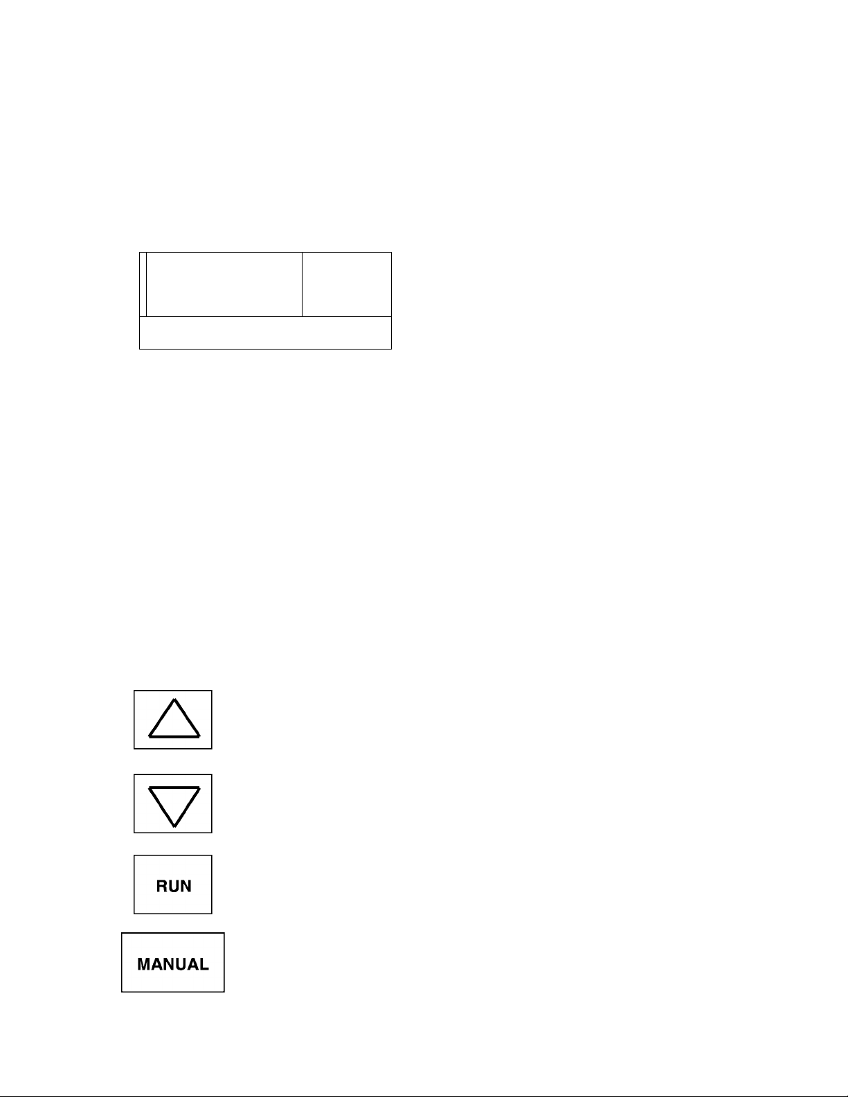
The following chart explains each of the key functions on the keypad
Keys and Functions
Key
Up scroll key used for increasing frequency or data values, scrolls parameter to
parameter, or upwards scaling of remote meters (FM, AM).
Down scroll key used for decreasing frequency or data values, scrolls parameter
to parameter, or downwards scaling of remote meters (FM, AM).
Used to start a normal forward/reverse run (only in manual mode), manual LED
will flash in run mode even at frequency = 0 Hz.
AUTO
Function
Key enables the manual control mode and allows commands to be entered from
either the keypad or a computer terminal. The Manual control LED is on when
operating in the manual control mode. When switching to auto mode, first press
"off" key; otherwise inverter must be at 0 Hz. If "auto" key is pressed while still
running in manual mode, an ":Err. 7" will flash.
6-1
6.2 Operating Panel Keys and Functions (cont'd)
Keys and Functions
Key disables RUN or STOP commands until either the AUTO or MANUAL
key is pressed. Display reads "OFF". Motor coasts to a stop if key is pressed
while motor is running
Disables manual control and turns the manual control LED off; drive will accept
commands from terminal strip connector or computer input only.
This key is used to scroll through the system parameters (see page 7-2), read
READ
WRITE
data from within the group or setup parameters, write data changes into the
non-volatile memory. System status information is available while drive is
running.
Key used to scroll through the parameter groups and returns to frequency
setting if in any other mode.
TOSHIBA
CLEAR
RESET
When data changes have been made in error, this key will allow user to clear
data back to data = 0 (if allowed). Also resets trips, or returns to frequency
mode.
This key stops the drive in manual mode. The manual mode stop can be
programmed to coast or decelerate to a stop. Will cause the drive to trip and
coast in any other mode. Can be used as an emergency stop in any mode.
Allows access to setup parameters only and will automatically return to
frequency mode after all parameters have been stepped through.
6-2
TOSHIBA
6.3 LED Display and Display Monitoring
The LED display provides the user with the operating frequency, function settings, and
status information necessary to easily monitor and set the operating parameters. The
individual LED's are identified and explained in the following chart.
Display Monitoring
Item Name Function/status
o
©
©
©
©
Monitor display 7-segment, 4-column LED
Displays frequency, title, data, etc.
Panel control LED ON when the unit Is In the manual control mode
OFF when the unit Is In the auto (remote) control mode
FLASHING when the unit is in the manual control mode and the motor is running
Option mode LED ON when the computer interface option is enabled. (Contact Toshiba
for information.)
Both LED's are normally OFF when the monitor is displaying operating
Monitor display
o
frequency or scaled operating frequency from the display scaler.
o
'•
LED 5 is ON and LED 4 is OFF when unit is in a patterned run sequence.
o
Both LED's are ON when the unit is in the parameter setting mode using
the operating panel keypad and the motor is not running.
•
Both LED's are FLASHING when the unit is in the parameter setting mode
~0
using the operating panel keypad and the motor is running.
0
LED 4 is ON and LED 5 is OFF when the unit is in the parameter setting
o'
mode and the operating panel keypad is disabled.
•
(Computer Command Mode)
©
©
©
Hz display LED ON when the display is indicating frequency.
% display LED ON when the display is indicating a percentage.
Time display LED ON when displaying time in seconds.
6-3

6.4 Display Alphanumerics
The 7 segment LED display is able to display all of the numerals but is unable to
properly form all of the characters of the alphabet. Therefore some characters of the
alphabet will appear as special symbols and others are not used at all. The tables
below show the numbers and characters that are used and how each appears on the
7 segment display.
TOSHIBA
Numerics LED display
0
1
2
3
4
5
6
7
8
9
/_/
l_
1 1
/_/
/_/
_l
n
/
/
~l
~l
1
l~
_f
l~
1
1
n
n
Characters LED display
A
b
C
d
E
F
G
H
1
1
J
L
M
n
1 1
1
u
r
l_
1
u
r
l_
r
1
r
u
1 1
1 1
1
1
1
u
1
l_
n
1 1
6-4
O
u
y
n
n
LI or U
P
r
S
t
V
-
n
1
r
1
1 1
u
LI
1 1
J
-
r
J
l_
Loading...