

NETWORK CAMERA
Model:
IK-WD31A
User's Manual
For information on our latest products and peripheral devices, refer to the
following Website:
http://www.toshibasecurity.com
If the URL changes, refer to the Toshiba website (http://www.toshiba.com/).

Table of Contents
Introduction������������������������������������������������������������������������������������������������������������������������������������������������������������������ 4
ImportantSafeguards�������������������������������������������������������������������������������������������������������������������������������������������������� 6
ImportantSafeguards(Cont�)�������������������������������������������������������������������������������������������������������������������������������������� 8
NotesonUseandInstallation�������������������������������������������������������������������������������������������������������������������������������������� 9
PrecautionsforUse��������������������������������������������������������������������������������������������������������������������������������������������������� 10
PackageContents����������������������������������������������������������������������������������������������������������������������������������������������������� 11
PhysicalDescription�������������������������������������������������������������������������������������������������������������������������������������������������� 12
PhysicalDescription�������������������������������������������������������������������������������������������������������������������������������������������������� 14
Installation�����������������������������������������������������������������������������������������������������������������������������������������������������������������17
Hardware Installation ............................................................................................................................................ 17
Network Deployment ............................................................................................................................................ 17
Software Installation ............................................................................................................................................. 19
Ready to Use ........................................................................................................................................................ 20
AccessingtheNetworkCamera�������������������������������������������������������������������������������������������������������������������������������� 21
Using Web Browsers ............................................................................................................................................ 21
Using RTSP Players ............................................................................................................................................. 23
Using 3GPP-compatible Mobile Devices .............................................................................................................. 24
MainPage�����������������������������������������������������������������������������������������������������������������������������������������������������������������25
System > General settings ................................................................................................................................... 32
System > Homepage layout ................................................................................................................................ 34
System > Logs ..................................................................................................................................................... 37
System > Parameters .......................................................................................................................................... 38
System > Maintenance ......................................................................................................................................... 39
Security > User Account ....................................................................................................................................... 43
Security > HTTPS (Hypertext Transfer Protocol over SSL).................................................................................44
Security > Access List ......................................................................................................................................... 49
Network > General settings .................................................................................................................................. 54
Network > Streaming protocols ............................................................................................................................ 62
Network > SNMP (Simple Network Management Protocol) ................................................................................. 69
Audio and Video > Image .................................................................................................................................... 70
Audio and Video > Stream ................................................................................................................................... 81
Audio and Video > Audio ...................................................................................................................................... 90
PTZ > PTZ settings .............................................................................................................................................. 91
Event > Event settings ......................................................................................................................................... 94
Applications > Motion detection.......................................................................................................................... 108
Applications > DI and DO ....................................................................................................................................111
Applications > Tampering detection ....................................................................................................................111
Applications > Audio detection ......................................................................................................................... 112
Applications > Extension Platform ...................................................................................................................... 114
Recording > Recording settings ........................................................................................................................ 116
Local storage > SD card management ............................................................................................................... 121
2

Local storage > Content management ............................................................................................................... 122
Troubleshooting������������������������������������������������������������������������������������������������������������������������������������������������������� 124
Specications����������������������������������������������������������������������������������������������������������������������������������������������������������125
AppearanceDiagram����������������������������������������������������������������������������������������������������������������������������������������������� 127
TechnologyLicenseNotice�������������������������������������������������������������������������������������������������������������������������������������� 128
End-userLicenseAgreementonFreeSoftwareComponentsUsedintheTOSHIBANetworkCamera���������������� 129
Trademarks��������������������������������������������������������������������������������������������������������������������������������������������������������������134
3

Introduction
FCC (USA)-INFORMATION
NOTE:
device, pursuant to Part 15 of the FCC Rules. These limits are designed to provide reasonable
protection against harmful interference in a residential installation. This equipment generates,
uses and can radiate radio frequency energy and, if not installed and used in accordance with
the instructions, may cause harmful interference to radio communications. However, there is no
guarantee that interference will not occur in a particular installation. If this equipment does cause
harmful interference to radio or television reception, which can be determined by turning the
equipment off and on, the user is encouraged to try to correct the interference by one or more of
the following measures:
● Reorient or relocate the receiving antenna.
● Increase the separation between the equipment and receiver.
● Connect the equipment into an outlet on a circuit different from that to which the receiver is
● Consult the dealer or an experienced radio/TV technician for help.
USER-INSTALLER CAUTION:
be voided if you make changes or modications not expressly approved by the party.
This equipment has been tested and found to comply with the limits for a Class B digital
connected.
Shielded interface cables must be used in order to comply with emission limits.
Your authority to operate this FCC veried equipment could
4

Thank you for purchasing the IK-WD31A Network Camera. Before using the camera, read this
User's Manual carefully to ensure correct usage. After reading this User's Manual, save it for
future reference.
The design, specications, software, and User's Manual contents are subject to change without
prior notice.
Terms
l
The term "OS" is used in this manual to indicate operating systems compatible with this
product.
-- Microsoft® Windows Vista® Business Edition
-- Microsoft® Windows® 7 Professional Edition
NOTE
● The performance of the network camera may vary depending on the network environment.
● When using multiple network cameras, the appropriate network switch and PC are required.
● This camera does not support MAC-PC.
5

Important Safeguards
1. Read Instructions
Read all the safety and operating instructions before operating the product.
2. Retain Instructions
Retain the safety instructions and user's manual for future reference.
3. Warnings
Comply with all warnings on the product and in the user's manual.
4. Follow Instructions
Follow all operating and use instructions.
5. Cleaning
Disconnect this camera from the power supply before cleaning
.
6. Attachments
D
o not use attachments not recommended by the camera manufacturer as they may pose
safety risks.
7. Water and Moisture
Do not use this camera near water. Some examples are: near a bath tub, wash bowl, kitchen
sink, or laundry tub, in a wet basement, or near a swimming pool.
8. Accessories
Do not place this camera on an unstable cart, stand, tripod, bracket or table. The camera
may fall, causing serious injury to a person, or serious damage to the product. Use only with
stand, tripod,bracket,or table recommended by the manufacturer, or sold with the camera.
Any mounting of the product should follow the manufacturer's instructions, and should use a
mounting accessory recommended by the manufacturer.
9. Ventilation
T
his camera should never be placed near or over a radiator or heat register. If this product
is placed in a built-in installation, verify that there is proper ventilation so that the camera
temperature operates within the recommended temperature range
.
10. Power Sources
This camera should be operated only from the type of power source indicated on the
information label. If you are not sure of the type of power supply at your location, consult your
product dealer.
11. Power-Cord Protection
Power cords should be routed so that they are not likely to be walked on or pinched by items
placed upon or against them. Pay particular attention to cords at plugs, screws and the point
where they exit the product.
12. Installation
Install this camera on a secure part of the ceiling or wall. If installed on an unsecured location,
the camera could fall causing injury and damage.
6

13. Lightning
For additional protection on this camera during a lightning storm, or when it is left unattended
and unused for long periods of time, unplug it from the wall outlet and disconnect the power
supply and cable system. This will prevent damage to the camera due to lightning and powerline surges. If lightning occurs, do not touch the unit or any connected cables in order to avoid
electric shock.
14. Overloading
Do not overload the power supply or extension cords as this can result in a risk of re or
electric shock.
15. Object and Liquid Entry
Never push objects of any kind into this camera through openings as they may touch
dangerous electrical points or short-out parts that could result in a re or electrical shock.
Never intentionally spill liquid of any kind on the camera.
16. Servicing
Do not attempt to service this camera yourself as opening or removing covers may expose
you to dangerous electrical or other hazards. Refer all servicing to qualied service personnel.
17. Damage Requiring Service
Disconnect this camera from the power supply and refer servicing to qualied service
personnel under the following conditions.
a. When the power-supply cord or plug is damaged.
b. If liquid has been spilled, or objects have fallen into the camera.
c. If the camera has been submerged in water.
d. If the camera does not operate normally by following the operating instructions in the user's
manual. Adjust only those controls that are covered by the user's manual as an improper
adjustment of other controls may result in damage and will often require extensive work by
a qualied technician to restore the camera to its normal operation.
e. If the camera has been dropped or the cabinet has been damaged.
f. When the camera exhibiting a distinct change in performance which indicates a need for
service.
g. Other trouble.
18. Replacement Parts
When replacing parts, be sure the service technician uses parts specied by the manufacturer
or have the same characteristics as the original part. Unauthorized substitutions may result in
re, electric shock or other hazards.
19. Safety Check
Upon completion of any service or repairs to this camera, ask the service technician to
perform safety checks to determine that the camera is in proper operating condition.
7

Important Safeguards (Cont.)
CAUTION TO REDUCE THE RISK OF ELECTRIC SHOCK.
DO NOT REMOVE COVER. NO USER SERVICEABLE PARTS INSIDE. REFER
SERVICING TO QUALIFIED SERVICE PERSONNEL.
The lightning ash with arrowhead symbol, within an equilateral triangle,
is intended to alert the user to the presence of uninsulated "dangerous
voltage" within the product's enclosure that may be of sufcient
magnitude to constitute a risk of electric shock to persons.
The exclamation point within an equilateral triangle is intended to alert
the user to the presence of important operating and maintenance
(servicing) instructions in the literature accompanying the appliance.
WARNING:
TO REDUCE THE RISK OF FIRE OR
ELECTRIC SHOCK, DO NOT EXPOSE THIS
APPLIANCE TO RAIN OR MOISTURE.
FIELD INSTALLATION MARKING:
WORDED: “THIS INSTALLATION SHOULD BE MADE BY A QUALIFIED SERVICE
PERSON AND SHOULD CONFORM TO ALL LOCAL CODES.”
This product is intended to be supplied by a Listed Power Adapter with LPS, rated PoE
36~57V, 0.35~0.15A or 12V DC, 1.0A minimum.
The product is not likely to require connection to an Ethernet network with outside plant
routing, including campus environment; and the installation instructions clearly state that the
ITE is to be connected only to PoE networks without routing to the outside plant.
Ce produit est conçu pour être alimenté par un adaptateur secteur Listed avec LPS, classé
PoE 36~57V, 0.35~0.15A ou 12V DC, 1.0A minimum.
Le produit ne est pas susceptible de nécessiter une connexion à un réseau Ethernet avec
l'extérieur routage des plantes, y compris l'environnement de campus; et les instructions
d'installation clairement que l' état ITE doit être raccordé uniquement aux réseaux PoE sans
routage vers le installations extérieures.
8

Notes on Use and Installation
l
Do not aim the camera at the sun
Never aim the camera at the sun even with the camera power off.
l
Do not shoot intense light
Intense light such as a spotlight may cause a bloom or smear. A vertical stripe may appear on
the screen. However, this is not a malfunction.
l
Treat the camera with care
Dropping or subjecting the camera to intense vibration may cause it to malfunction.
l
Avoid Volatile Liquid
Do not use volatile liquids, such as an insect spray, near the unit. Do not leave rubber or
plastic products touching the unit for a long time. They will leave marks on the nish. Do not
use a chemically saturated cloth
l
Never touch internal parts
.
Do not touch the internal parts of the camera other than the parts specied
l
Keep the camera installation away from video noise
.
If cables are wired near electric lighting wires or a TV set, noise may appear in images. In this
event relocate cables or reinstall equipment.
l
Check the ambient temperature and humidity
Avoid using the camera where the temperature is hotter or colder than the specied operating
range. Doing so could affect the internal parts or cause the image quality to deteriorate.
Special care is required to use the camera at high temperature and humidity.
l
Should you notice any trouble
If any trouble occurs while you are using the camera, turn off the power and contact your
dealer. If you continue to use the camera when there is something wrong with it, the trouble
may get worse and an unpredictable problem may occur.
9

Precautions for Use
Disclaimer
We disclaim any responsibility and shall be held harmless for any damages or losses
incurred by the user in any of the following cases:
1. Fire, earthquake or any other act of God; acts by third parties; misuse by the user, whether
intentional or accidental; use under extreme operating conditions.
2. Malfunction or non-function resulting in indirect, additional or consequential damages,
including but not limited to loss of expected income and suspension of business activities.
3. Incorrect use not in compliance with instructions in this user's manual.
4. Malfunctions resulting from misconnection to other equipment.
5. Repairs or modications made by the user or caused to be made by the user and carried out
by an unauthorized third party.
Notwithstanding the foregoing, Toshiba's liabilities shall not, in any circumstances, exceed the
purchase price of the product.
Copyright and Right of Portrait
There may be a conict with the Copyright Law and other laws when a customer uses, displays,
distributes, or exhibits an image picked up by the camera without permission from the copyright
holder. Please also note that transfer of an image or le covered by copyright is restricted to use
within the scope permitted by the Copyright Law.
Protection of Personal Information
Images taken by the camera that reveal the likeness of an individual person may be considered
personal information. To disclose, exhibit or transmit those images over the internet or otherwise,
consent of the person may be required.
Usage Limitation
The product is not designed for any "critical applications." "Critical applications" means life
support systems, exhaust or smoke extraction applications, medical applications, commercial
aviation, mass transit applications, military applications, homeland security applications, nuclear
facilities or systems or any other applications where product failure could lead to injury to
persons or loss of life or catastrophic property damage.
Accordingly, Toshiba disclaims any and all liability arising out of the use of the product in any
critical applications.
10

Package Contents
NETWORK CAMERA
Model:
IK-WD31A
User's Manual
If the URL changes, refer to the Toshiba website (http://www.toshiba.com/).
For information on our latest products and peripheral devices, refer to the
following Website:
http://www.toshibasecurity.com
IK-WD31A
l
CD-ROM
l
AV Out Cable
l
Alignment Sticker
l
Warranty Card
l
Torx driver
l
P/N : 62XXXXXXXG
Quick Start Guide and Important
l
Safeguards
Screws and Anchors
l
11
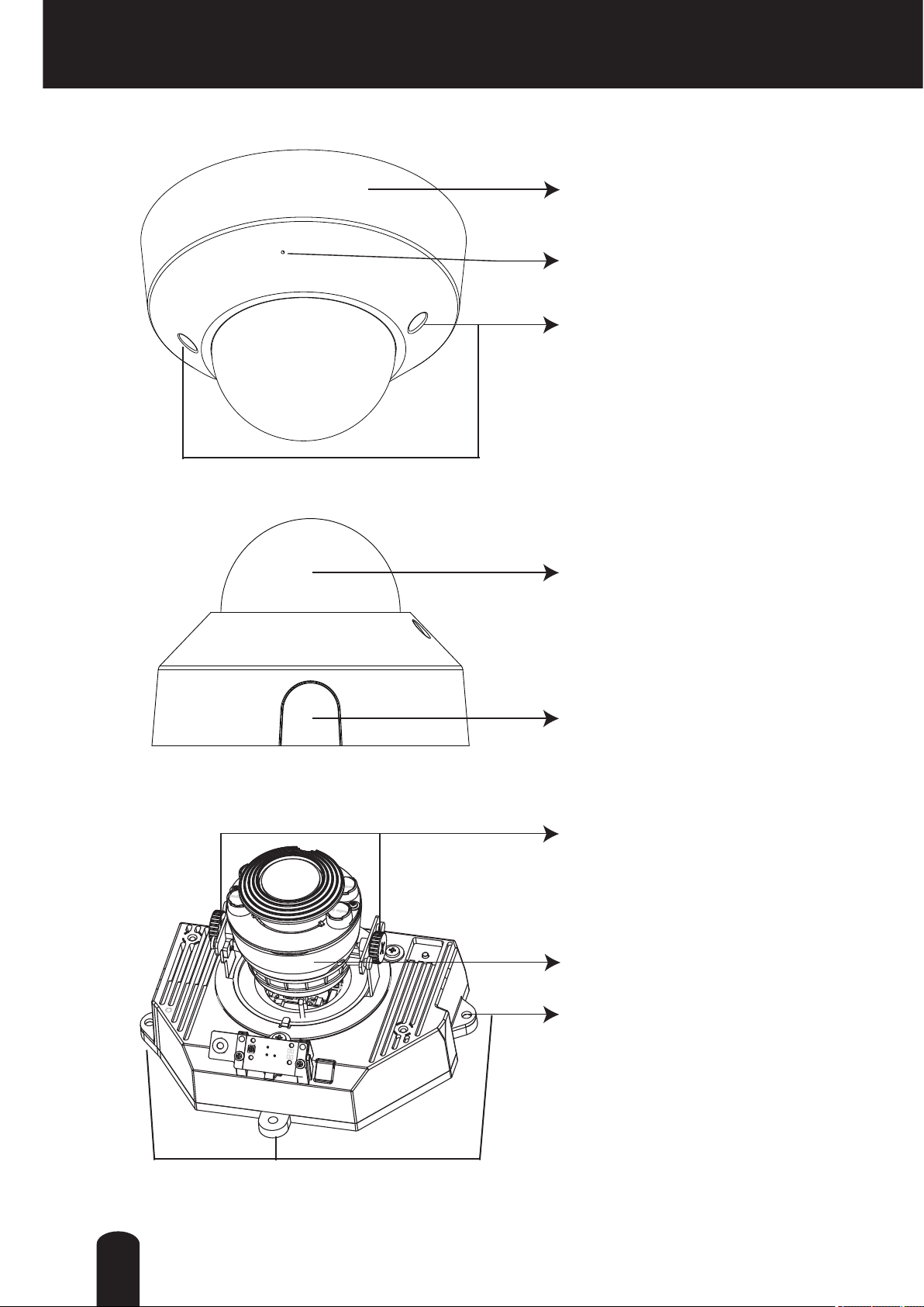
Physical Description
Dome cover
Internal microphone
Cover screws
Clear cover
Knock out
Tilt adjustment screws
Lens cover
Mounting holes
12
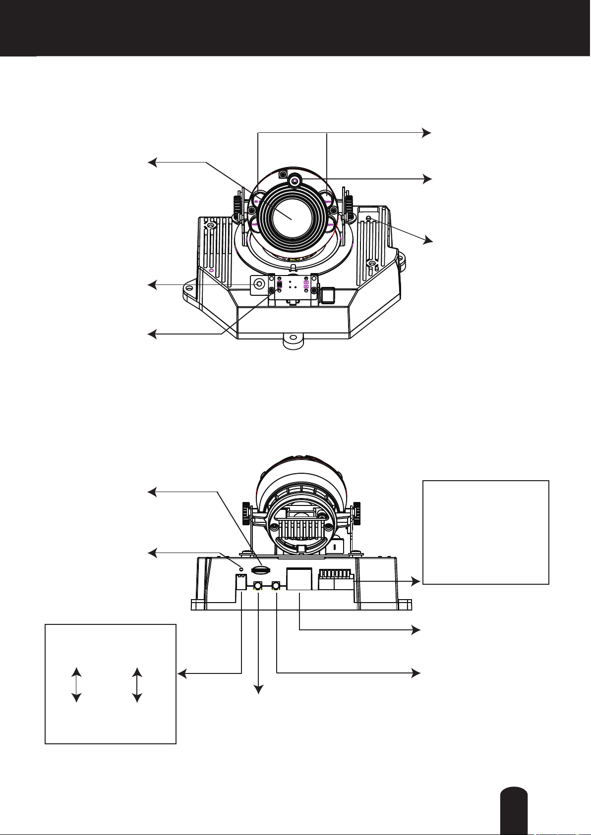
CAMERA MAIN UNIT
Front View
l
Lens
Built-in
Microphone
StatusLED
IR LEDs
Light Sensor
Focus Button
Rear View
l
SDHC/SDXC
Reset Button
DIP switch
Microphone
internal
external
1
Micro SD/
Card Slot
Recessed
Video Output
NTSC
60Hz
PAL
50Hz
2
General IO
Terminal Block
1. GND
2. Power input (12V DC)
3. Do not use
4. Do not use
5. Signal GND
6. Digital Input
7. Digital output
8. 12V DC Output
10/100BaseT
Ethernet Socket
MIC In
(Printed "Audio In")
Audio/Video Out
(Printed "AV Out")
13

Physical Description
General I/O Terminal Block
This Network Camera provides a general I/O terminal block which is used to connect
external input / output devices.
NOTE
● 12V DC is outputted from 8-pin only when connected to a power supply.
The diagrams below apply when "Digital Input" is used for an alarm input.
14

Status LED
The LED indicates the status of the Network Camera.
Item LED status Description
1 Steady Red Powered and system booting
Red LED off Power off
2 Steady Red Network failed
Red LED blinks every 1 sec.
(on for 1 sec. and off for
antoher)
3 Blinks RED every 0.15 sec.
(on for 0.15 sec. and off for
another)
4 Blinks RED every 0.15 sec.
(on for 0.15 sec. and off for
another)
Connected to network (heartbeat) and BRB
mode (Back Recovery Booting)
Upgrading rmware.
Restoring defaults.
Hardware Reset
The reset button is used to reset the system or restore the factory default settings. Occasionally
resetting the system can return the camera to normal operation. If the system problems remain
after resetting, restore the factory settings and install again.
Reset:Hold for about 3 seconds and release the recessed reset button with a paper clip or small
object. Wait for the Network Camera to reboot.
Restore:Press and hold the recessed reset button until the status LED rapidly blinks. It takes
about 10 seconds. Note that all settings will be restored to factory default. Upon successful
restore, the status LED will blink during normal operation.
Restoring the factory defaults will erase any previous settings.
15

SD/SDHC/SDXC Card and Capacity
This network camera is compliant with Micro SD/SDHC/SDXC 64GB and other preceding
standard Micro SD cards for local storage.
NOTE
● There is a limit to the number of rewrites that is possible with the SD memory card. Replacing
the SD memory card when performing periodic maintenance of the camera is recommended.
● Do not use 512MB and below SD memory cards.
● The Camera system reserves approximately 60MB in SD memory cards. Any images are not
recordable on this space.
● Carefully read the User’s guide, precautions on use, and any other information supplied with a
purchased memory card.
● An SD memory card can be used for repeated storage. The lifespan (number of rewrites
possible) of an SD memory card is greatly affected by the capacity of the SD memory card.
● Do not use a memory card containing the data recorded by another device with the camera as
this may result in the camera not functioning correctly.
● Do not modify, overwrite the data, or change the folder name of an SD memory card. It may
result in the camera not to function correctly.
● If you unmount or remove the SD memory card from camera, you have to turn OFF the
recording status in Recording window on page 116.
16

Installation
Hardware Installation
Please verify that your product package contains all the accessories listed in the Package
Contents listed on page 11. Depending on the user’s application, an Ethernet cable may
be needed. The Ethernet cable should meet the specs of UTP Category 5 or higher.
Hardware Installation is shown in the Quick Start Guide(QSG). Please refer to page 13 of the
QSG.
Network Deployment
In this user’s manual, “User” refers to whoever has access to the Network Camera,
and “Administrator” refers to the person who can congure the Network Camera and
grant user access to the camera.
Network Deployment is shown in the Quick Start Guide(QSG). Please refer to page 15 of the
QSG.
Setting up the Network Camera over the Internet
There are several ways to set up the Network Camera over the Internet. The rst way is to set
up the Network Camera behind a router. The second way is to utilize a static IP. The third way is
to use PPPoE.
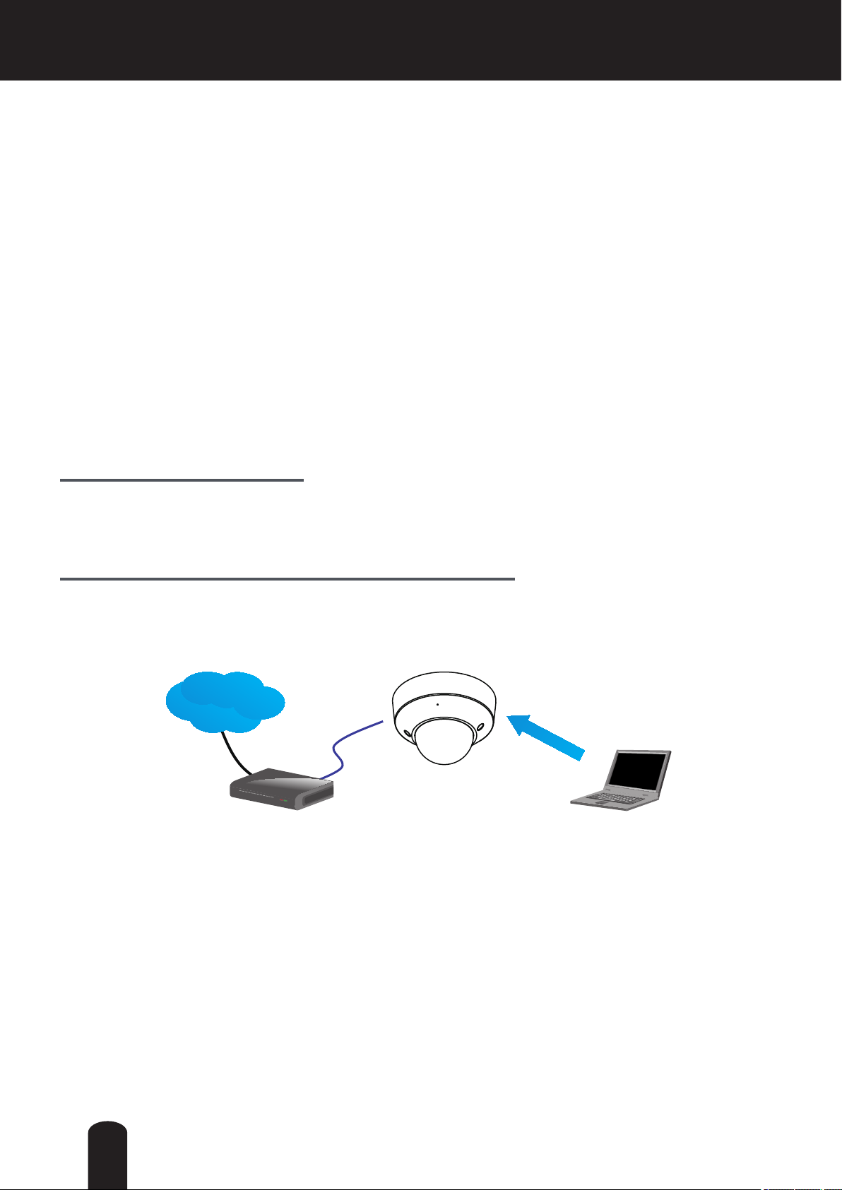
Internet connection via a router
Before setting up the Network Camera over the Internet, make sure you have a router and follow
the steps below.
1. Connect your Network Camera behind a router, the Internet environment is illustrated below.
Regarding how to obtain your IP address, please refer to Software Installation on page 19 for
details.
IP address : 192.168.0.3
Subnet mask : 255.255.255.0
Default router : 192.168.0.1
Inte rnet
WAN (Wide Area Network )
Router IP address : from ISP
LINK
POWER
COLLISION
RECEIVE
1
2
PARTITION
3
4
5
Cable or DSL Modem
Example Network Environment
LAN (Local Area Network)
Router IP address : 192.168.0.1
This client PC sets up
a camera and a router.
IP address : 192.168.0.2
Subnet mask : 255.255.255.0
Default router : 192.168.0.1
17
2. In this case, if the Local Area Network (LAN) IP address of your Network Camera is
192.168.0.3, please forward the following ports for the Network Camera on the router.
■ HTTP port: default is 80
■ RTSP port: default is 554
■ RTP port for audio: default is 5558
■ RTCP port for audio: default is 5559
■ RTP port for video: default is 5556
■ RTCP port for video: default is 5557
If you have changed the port numbers on the Network page, please open the ports accordingly
on your router. For information on how to forward ports on the router, please refer to your
router’s user’s manual.
3. Determine the public IP address of your router provided by your ISP (Internet Service
Provider). Use the public IP and the secondary HTTP port to access the Network Camera
from the Internet. Please refer to Network Type on page 54 for details.
Internet connection with static IP
Choose this connection type if you are required to use a static IP for the Network Camera.
Please refer to LAN on page 54 for details.
Internet connection via PPPoE (Point-to-Point over Ethernet)
Choose this connection type if you are connected to the Internet via a DSL Line. Please refer to
PPPoE on page 55 for details.
Internet
ADSL Modem
18
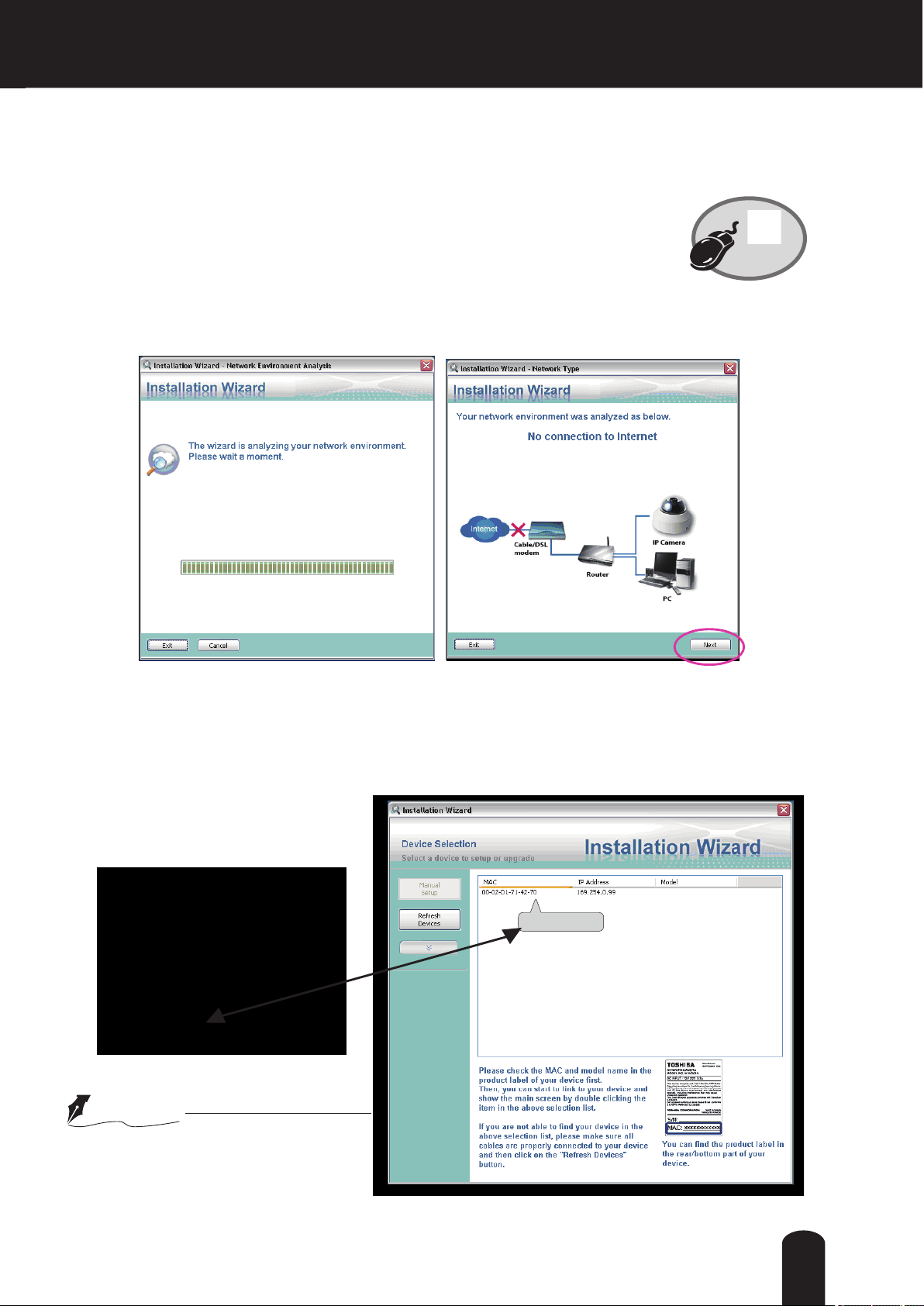
Software Installation
Installation Wizard (IW), a free-bundled software packaged in the product CD, helps to set up
your Network Camera in a LAN.
1. Install the IW under the Software Utility directory from the software CD.
Double click the IW shortcut on your desktop to launch the program.
Installation
Wizard
2. The program will analyze your network environment. After your network environment is
analyzed, please click [Next] to continue the program.
3. The program will search for Network Cameras on the same LAN.
4. After searching, the main installer window will pop up. Click on the MAC and model name
which matches the MAC of the camera.
IK-WR12A
000 2D1 714 270
NOTE
● This Software is proprietary client
software for TOSHIBA Network
Camera.
19

Ready to Use
1. Access the Network Camera on the LAN.
2. Retrieve live video through a web browser.
Adjusting the Lens
Adjusting the Lens is shown in the Quick Start Guide (QSG). Please refer to 19 pages of QSG.
20

Accessing the Network Camera
This chapter explains how to access the Network Camera through web browsers, RTSP players
and 3GPP-compatible mobile devices.
Using Web Browsers
Use Installation Wizard to access the Network Cameras on the LAN.
If your network environment is not a LAN, follow these steps to access the Network Camera:
1. Launch your web browser (Microsoft
2. Enter the IP address of the Network Camera in the address eld. Press Enter.
3. The live video will be displayed in your web browser.
4. If it is the rst time installing the network camera, an information bar will pop up as shown
below. Follow the instructions to install the required plug-in on your computer.
®
Internet Explorer).
► By default, the Network Camera is not password-protected. To prevent unauthorized access,
it is highly recommended to set a password for the Network Camera.
For more information about how to enable password protection, please refer to Security on
page 43.
21
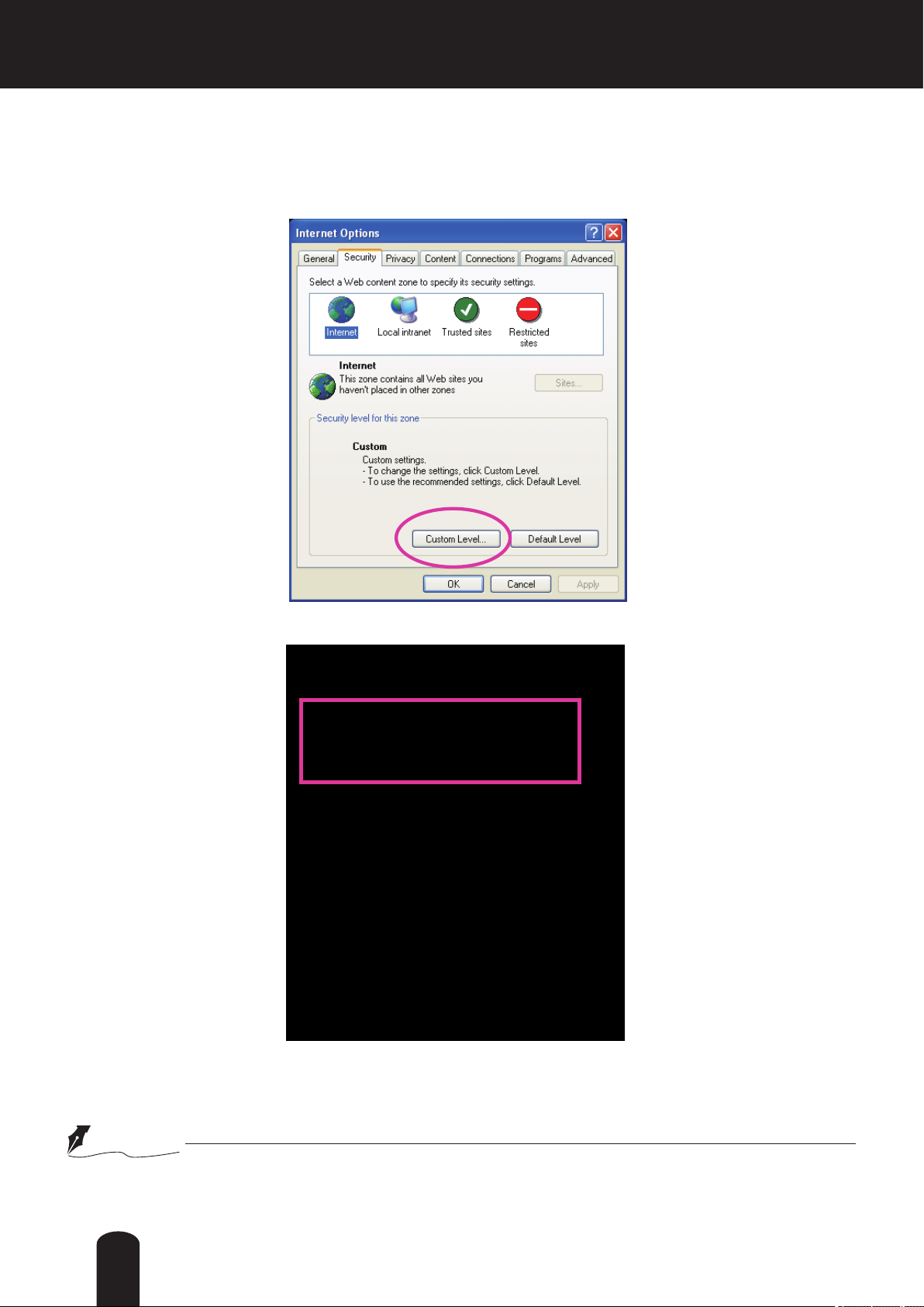
► If you see a dialog box indicating that your security settings prohibit running ActiveX®
®
Controls, please enable the ActiveX
Controls for your browser.
1. Choose Tools > Internet Options > Security > Custom Level.
2. Look for Download signed ActiveX
®
controls; select Enable or Prompt. Click OK.
3. Refresh your web browser, then install the Active X
complete installation.
®
control. Follow the instructions to
NOTE
● Currently the Network Camera utilizes 32-bit Active X® plug-in. You CAN NOT open a
Conguration/view session with the camera using a 64-bit IE browser.
22

Using RTSP Players
To view the H.264 streaming media using RTSP players, you can use players that support RTSP
streaming.
1. Launch the RTSP player.
2. Choose File > Open URL. A URL dialog box will pop up.
3. The address format is rtsp://<ip address>:<rtsp port>/<RTSP streaming access name for
stream1, stream2 or stream3>
As most ISPs and players only allow RTSP streaming through port number 554, please set the
RTSP port to 554. For more information, please refer to RTSP Streaming on page 63.
For example:
rtsp://xxx.xxx.xxx.xxx:554/live2.sdp
4. The live video will be displayed in your player.
For more information on how to configure the RTSP access name, please refer to RTSP
Streaming on page 63 for details.
Video 16:38:01 2010/01/15
23

Using 3GPP-compatible Mobile Devices
To view the streaming media through 3GPP-compatible mobile devices, make sure the Network
Camera can be accessed over the Internet. For more information on how to set up the Network
Camera over the Internet, please refer to Setup the Network Camera over the Internet on page
17.
To utilize this feature, please check the following settings on your Network Camera:
1. Because most players on 3GPP mobile phones do not support RTSP authentication, make
sure the authentication mode of RTSP streaming is set to disable.
For more information, please refer to RTSP Streaming on page 63.
2. As the bandwidth on 3G networks is limited, you will not be able to use a large video size.
Please set the video and audio streaming parameters as listed below.
For more information, please refer to Viewing Window on page 80.
Video Mode H.264
Frame size 176 x 144
Maximum frame rate 5 fps
Intra frame period 1S
Video quality (Constant bit rate) 40kbps
Audio type (GSM-AMR) 12.2kbps
3. As most ISPs and players only allow RTSP streaming through port number 554, please set
the RTSP port to 554. For more information, please refer to RTSP Streaming on page 63.
4. Launch the player on the 3GPP-compatible mobile devices.
5. Type the following URL commands into the player.
The address format is rtsp://<public ip address of your camera>:<rtsp port>/<RTSP streaming
access name for stream # with small frame size and frame rate>.
For example:
rtsp://xxx.xxx.xxx.xxx:554/live2.sdp
24

Main Page
This chapter explains the screen elements on the main page. It is composed of the following
sections: TOSHIBA Logo, Host Name, Camera Control Area, Conguration Area, and Live Video
Window.
Resize Button
TOSHIBA
Logo
Camera Control
Area
Live View Window
Host Name
Hide Button
Configuration
Area
Hide Button
TOSHIBA Logo
Click this logo to visit the TOSHIBA website.
Host Name
The host name can be customized to t your needs. For more information,
32.
please refer to
System on page
Camera Control Area
Video Stream: This Network Cmera supports multiple streams (stream 1 ~ 3) simultaneously. You can
select either one for live viewing. For more information about multiple streams, please refer to page 81
for detailed information.
Manual Trigger: Click to enable/disable an event trigger manually. Please configure an event setting
before enabling this function. A total of 3 or 4 event settings can be congured. For more information
about event setting, please refer to page 94. If you want to hide this item on the homepage, please go to
the System > Homepage Layout > General settings > Customized button to uncheck “show manual
trigger button”.
PTZ Panel: This Camera supports digital (e-PTZ) pan/tilt/zoom control. The e-PTZ control setting section
is displayed as the default control option. Please refer to page 91 for more information.
Digital Output: Click to turn the digital output device on or off.
25
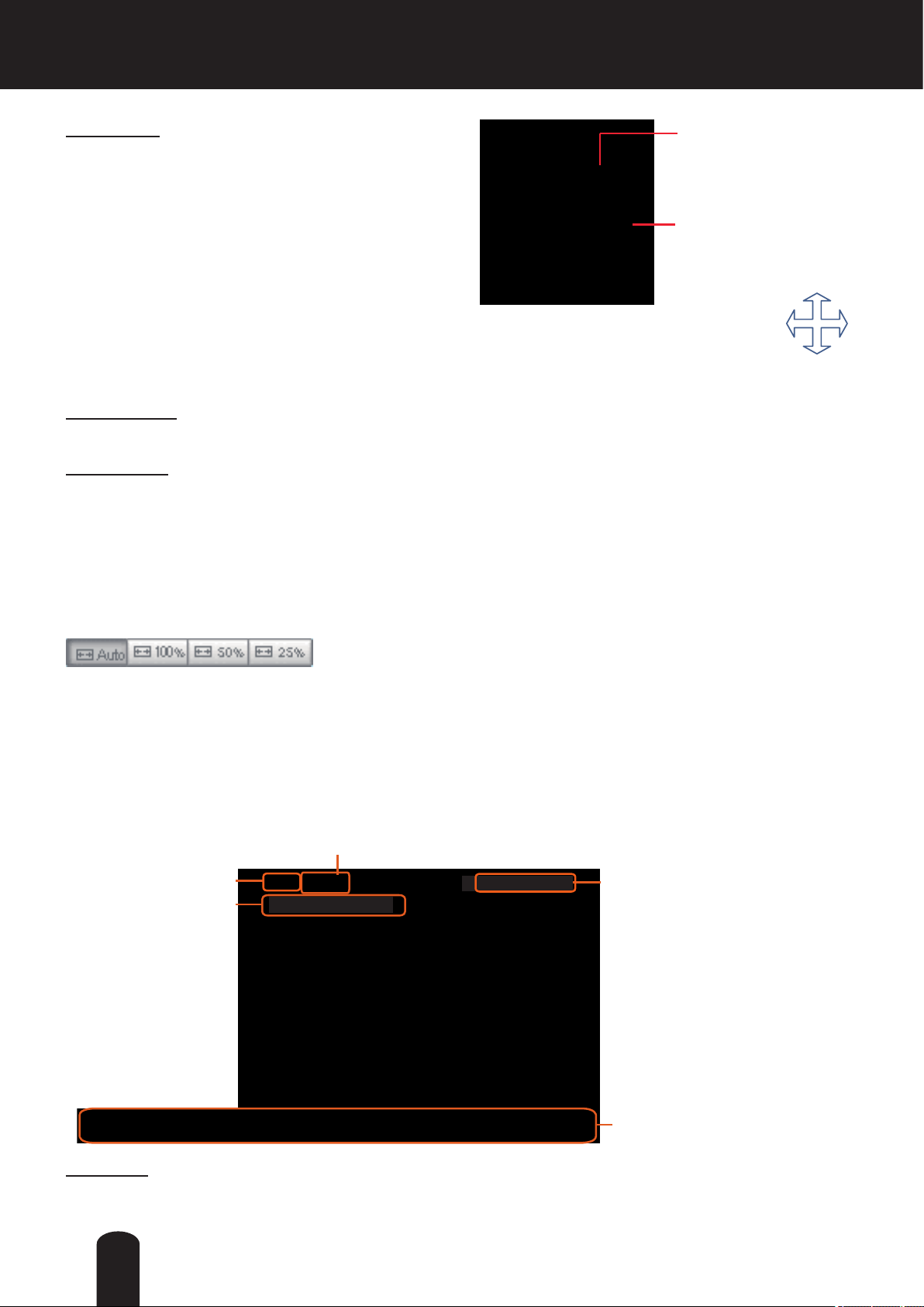
Global View: Click on this item to display the Global
Video and Audio Control Buttons
View window. The Global View window contains a full
view image (the largest frame size of the captured
The viewing region of
the current video
stream
video) and a oating frame (the viewing region of the
current video stream). The oating frame allows users
The largest frame size
to control the e-PTZ function (Electronic Pan/Tilt/
Zoom). For more information about e-PTZ operation,
please refer to E-PTZ Operation on page 91. For more
information about how to set up the viewing region of
the current video stream, please refer to page 82.
To move the current view window, place
your cursor on it and let the cursor
change to the all-direction arrow.
all-direction arrow
Conguration Area
Client Settings: Click this button to access the client setting page. For more information, please refer to
Client Settings on page 29.
Conguration: Click this button to access more of the conguration options provided with the Network
Camera. It is suggested that a password is applied to the Network Camera so that only the administrator
can configure the Network Camera. For more information, please refer to the description for the
Conguration menus on page 31.
Hide Button
You can click the hide button to hide the control panel or display the control panel.
Resize Buttons
:
Click the Auto button, the video cell will resize automatically to t the monitor.
Click 100% is to display the original homepage size.
Click 50% is to resize the homepage to 50% of its original size.
Click 25% is to resize the homepage to 25% of its original size.
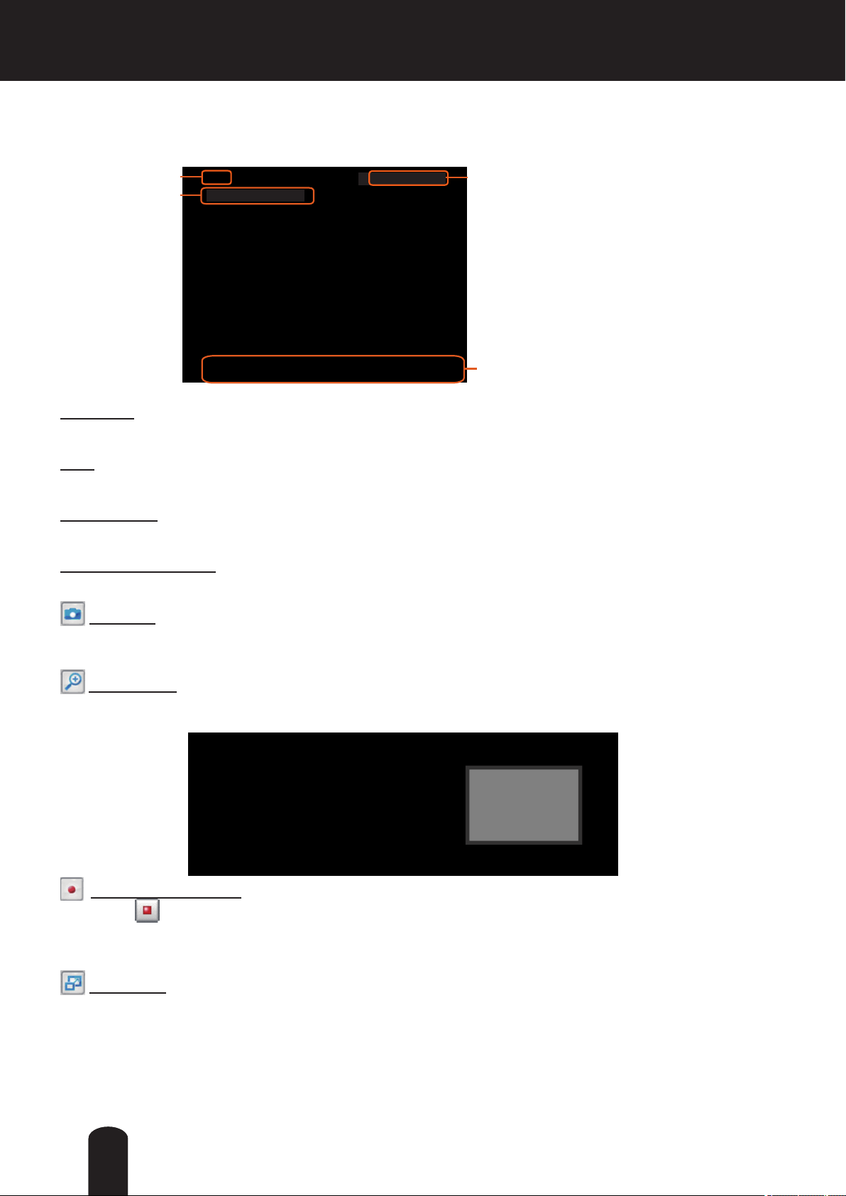
Live Video Window
■ The following window is displayed when the video mode is set to H.264:
H.264 Protocol and Media Options
Video Title
Title and Time
Video 17:08:56 2011/10/10
2011/10/10 17:08:56
Time
Video Title: The video title can be congured. For more information, please refer to Video settings on
page 70.
26
H.264 Protocol and Media Options: The transmission protocol and media options for H.264 video
streaming. For further conguration, please refer to Client Settings on page 29.
Time: Display the current time. For further configuration, please refer to Audio and Video > Image >
Genral settings on page 70.
Title and Time: The video title and time can be stamped on the streaming video. For further conguration,
please refer to Audio and Video > Image > Genral settings on page 70.
Video and Audio Control Buttons: Depending on the Network Camera model and Network Camera
conguration, some buttons may not be available.
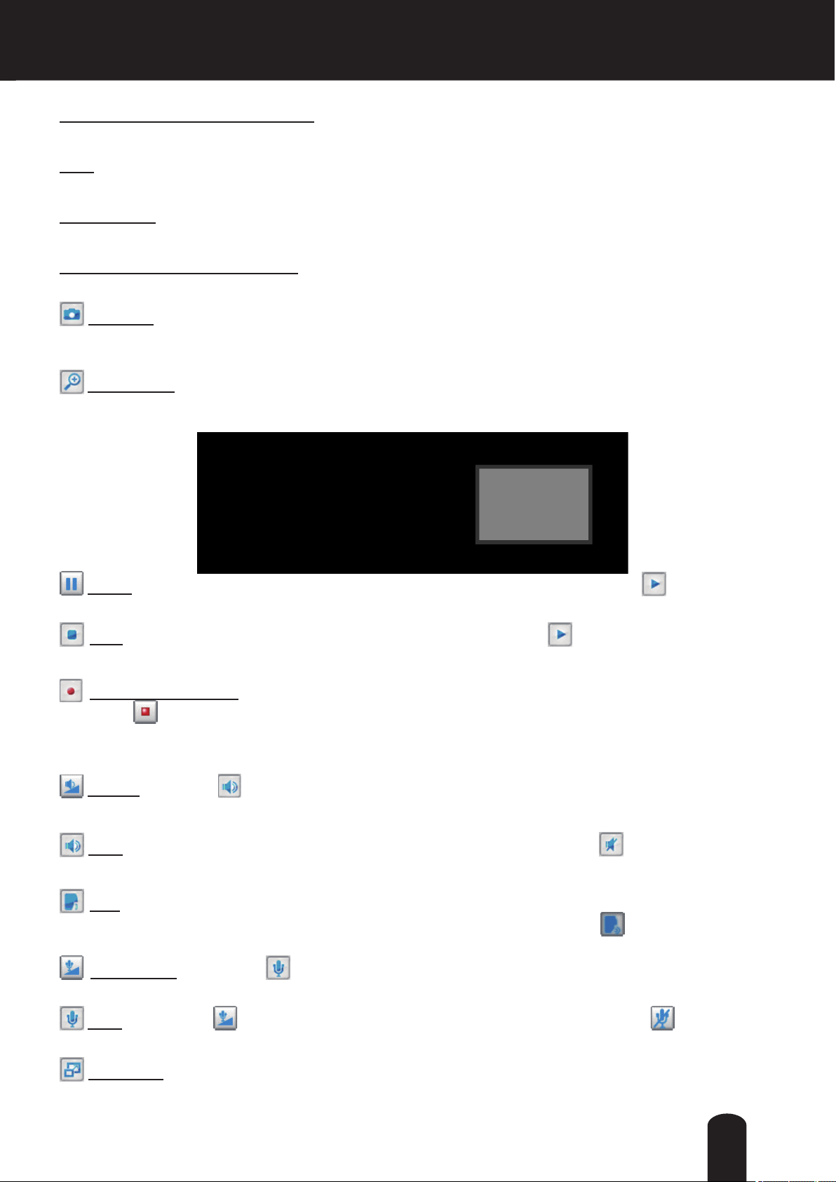
Snapshot: Click this button to capture and save still images. The captured images will be displayed
in a pop-up window. Right-click the image and choose Save Picture As to save it in JPEG (*.jpg) or BMP
(*.bmp) format.
Digital Zoom: Click and uncheck “Disable digital zoom” to enable the zoom operation. The navigation
screen indicates the part of the image being magnied. To control the zoom level, drag the slider bar. To
move to a different area you want to magnify, drag the navigation screen.
Pause: Pause the transmission of the streaming media. The button becomes the Resume button
after clicking the Pause button.
Stop: Stop the transmission of the streaming media. Click the Resume button to continue
transmission.
Start MP4 Recording: Click this button to record video clips in MP4 file format to your computer.
Press the
recording stops accordingly. To specify the storage destination and le name, please refer to MP4 Saving
Options on page 30 for details.
Volume: When the Mute function is not activated, move the slider bar to adjust the volume on the
local computer.
Mute: Turn off the volume on the local computer. The button becomes the Audio On button after
clicking the Mute button.
Talk: Click this button to talk to people around the Network Camera. Audio will project from
the external speaker connected to the Network Camera. Click this button
transmission.
Mic Volume: When the Mute function is not activated, move the slider bar to adjust the
microphone volume on the local computer.
Stop MP4 Recording button to end recording. When you exit the web browser, video
again to end talking
Mute: Turn off the Mic volume on the local computer. The button becomes the Mic On button
after clicking the Mute button.
Full Screen: Click this button to switch to full screen mode. Press the “Esc” key to switch back to normal
Mode.
27
■ The following window is displayed when the video mode is set to MJPEG:
Video Title
Title and Time
Video 17:08:56 2011/10/10
2011/10/10 17:08:56
Time
Video Control Buttons
Video Title: The video title can be congured. For more information, please refer to Audio and Video >
Image on page 70.
Time: Display the current time. For more information, please refer to Audio and Video > Image on page
70.
Title and Time: Video title and time can be stamped on the streaming video. For more information, please
refer to Audio and Video > Image on page 70
.
Video Control Buttons: Depending on the camera model and your current conguration, some buttons
may not be available.
Snapshot: Click this button to capture and save still images. The captured images will be displayed
in a pop-up window. Right-click the image and choose Save Picture As to save it in JPEG (*.jpg) or BMP
(*.bmp) format.
Digital Zoom: Click and uncheck “Disable digital zoom” to enable the zoom operation. The navigation
screen indicates the part of the image being magnied. To control the zoom level, drag the slider bar. To
move to a different area you want to magnify, drag the navigation screen.
Start MP4 Recording: Click this button to record video clips in MP4 file format to your computer.
Press the
Stop MP4 Recording button to end recording. When you exit the web browser, video
recording stops accordingly. To specify the storage destination and le name, please refer to MP4 Saving
Options on page 30 for details.
Full Screen: Click this button to switch to full screen mode. Press the “Esc” key to switch back to normal
mode.
2828
Client Settings
This chapter explains how to select the stream transmission mode and saving options on the
local computer. When completed with the settings on this page, click Save on the page bottom
to enable the settings.
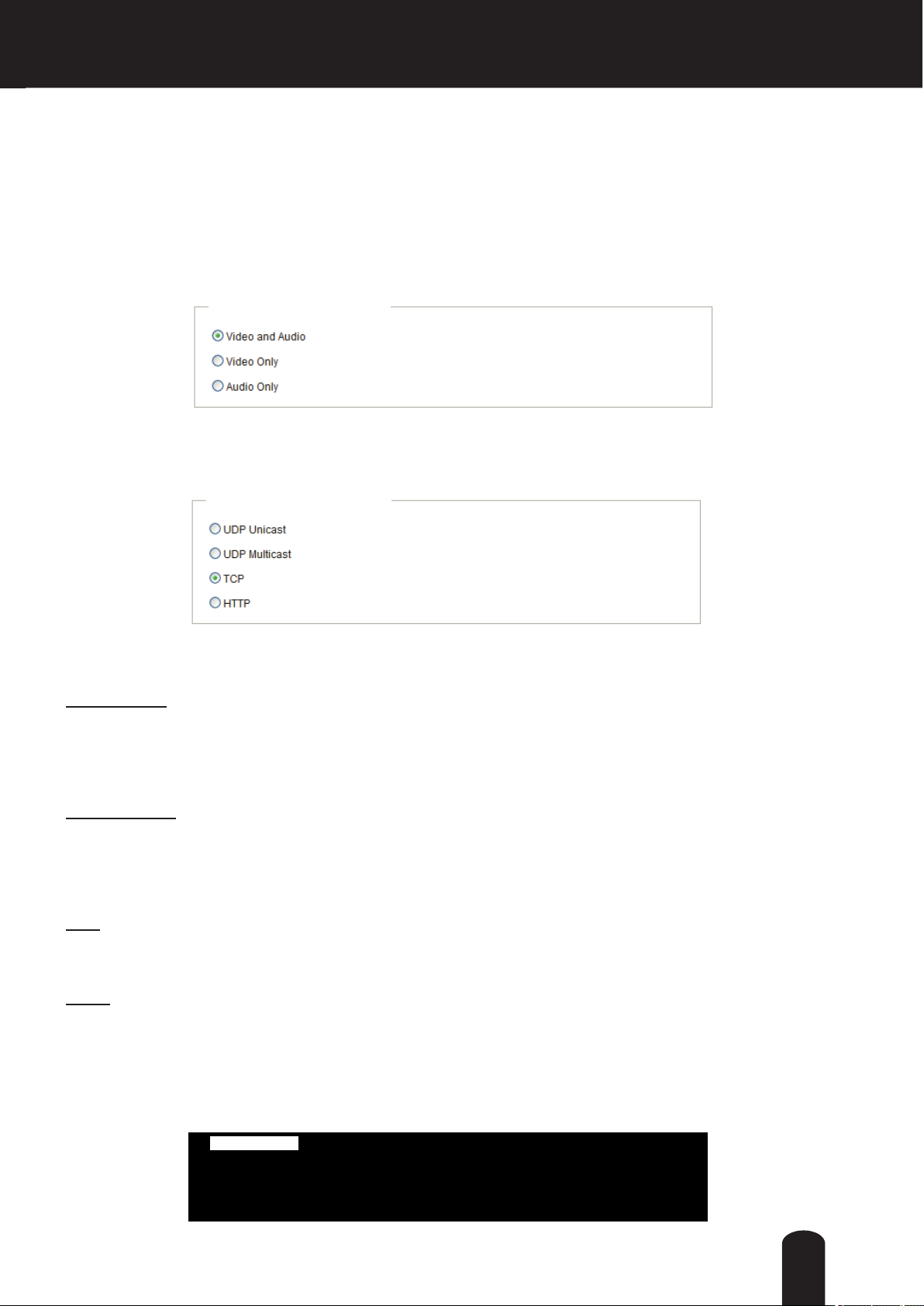
H.264 Media Options
H.264 Media Options
Select to stream video or audio data or both. This is enabled only when the video mode is set to H.264.
H.264 Protocol Options
H.264 Protocol Options
Depending on your network environment, there are four options with the transmission protocols with
H.264 streaming:
UDP unicast: This protocol allows for more real-time audio and video streams. However, network
packets may be lost due to network burst trafc and images may be broken. Activate UDP connection
when occasions require time-sensitive responses and the video quality is less important. Note that each
unicast client connecting to the server takes up additional bandwidth and the Network Camera allows up
to ten simultaneous accesses.
UDP multicast: This protocol allows multicast-enabled routers to forward network packets to all clients
requesting streaming media. This helps to reduce the network transmission load of the Network Camera
while serving multiple clients at the same time. Note that to utilize this feature, the Network Camera must
be configured to enable multicast streaming at the same time. For more information, please refer to
RTSP Streaming on page 63.
TCP: This protocol guarantees the complete delivery of streaming data and thus provides better video
quality. The downside of this protocol is that its real-time effect is not as good as that of using the UDP
protocol.
HTTP: This protocol allows the same quality as TCP protocol without needing to open specic ports for
streaming under some network environments. Users behind a rewall can utilize this protocol to allow
camera’s streaming data to pass through.
Two way audio
The half and Full-duplex modes determine the operation mode between the camera and the operator. In
Full-duplex mode, the client PC must have an audio codec capable of full-duplex functionality.
Two way audio
29
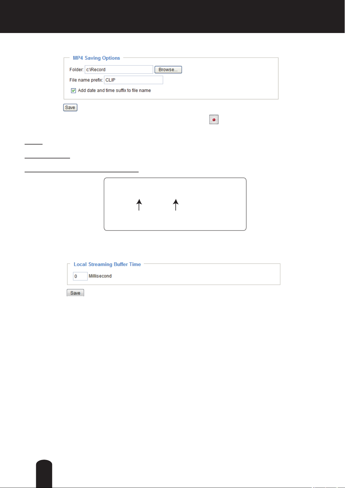
MP4 Saving Options
Users can record live video as they are watching it by clicking Start MP4 Recording on the main
page. Here, you can specify the storage destination and le name.
Folder: Specify a storage destination for the recorded video les.
File name prex: Enter the text that will be appended to the front of the video le name.
Add date and time sufx to the le name: Select this option to append the date and time to the end of the
le name.
CLIP_20100115-180853
File name prefix
Date and time suffix
The format is: YYYYMMDD_HHMMSS
Local Streaming Buffer Time
Due to unsteady bandwidth ow, live streaming may lag. If you enable this option, the live streaming will
be cached on the camera’s buffer memory before being played on the live viewing window. This helps
produce smoother live streaming. If you enter a value of 3000 milliseconds, the streaming will delay for 3
seconds.
3030

Conguration
Click Configuration on the main page to enter the camera setting pages. Note that only
Administrators can access the conguration page.
TOSHIBA offers an easy-to-use user interface that helps you set up your network camera with
minimal effort. To simplify the setting procedure, two types of user interfaces are available:
Advanced Mode for professional users and Basic Mode for entry-level users. Some advanced
functions (PTZ/ Event/ Recording/ Local storage) are not displayed in Basic Mode.
If you want to set up advanced functions, please click on [Advanced Mode] at the bottom of the
conguration list to switch to Advanced Mode.
In order to simplify the user interface, detailed information will be hidden unless you click on the
function item. When you click on the rst sub-item, the detailed information for the rst sub-item
will be displayed; when you click on the second sub-item, the detailed information for the second
sub-item will be displayed and that of the rst sub-item will be hidden.
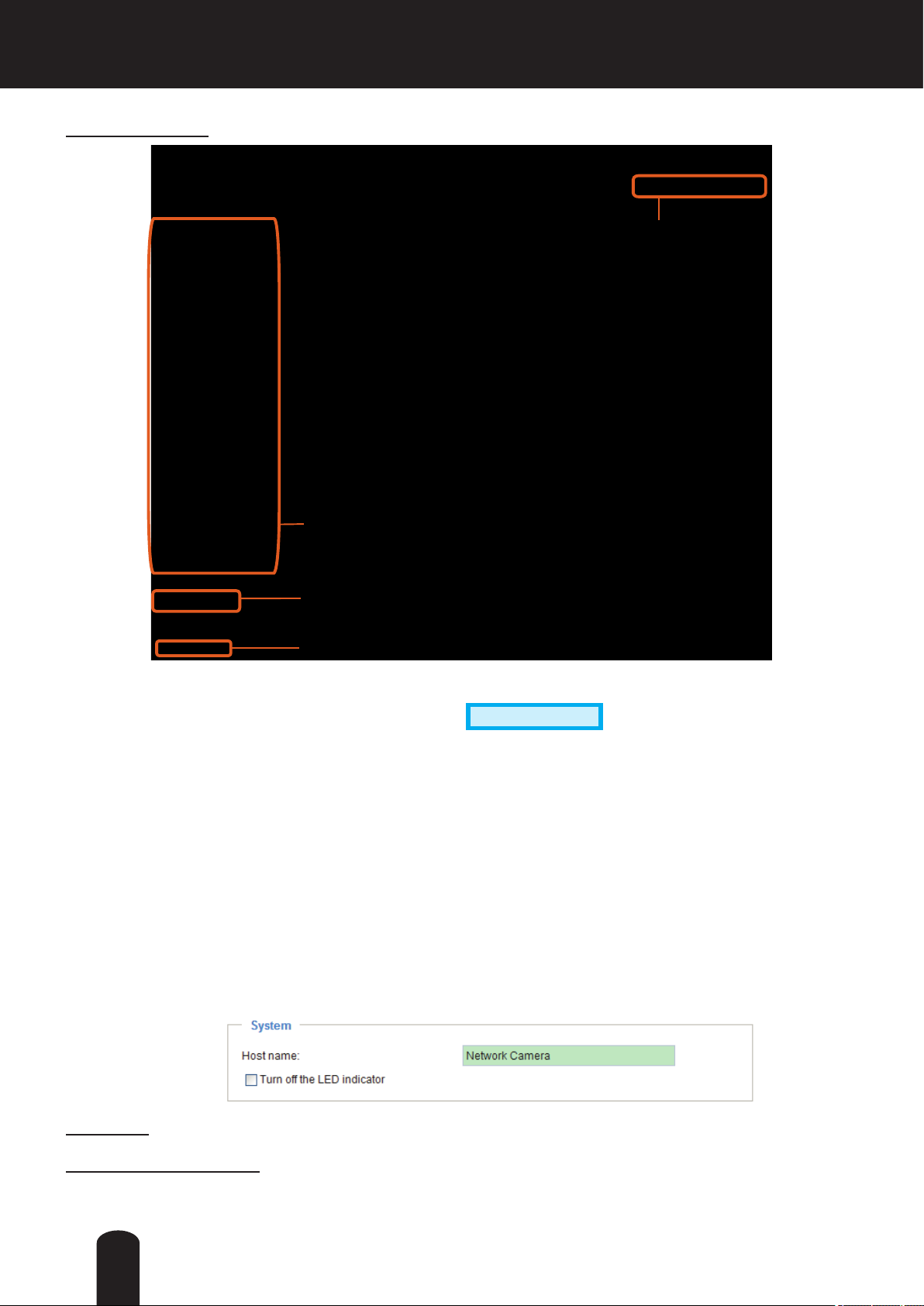
The following is the interface of the Basic Mode and the Advanced Mode:
Basic Mode
Navigation Area
Configuration List
Click to switch to Advanced Mode
Firmware Version
31
Advanced Mode
Navigation Area
Configuration List
Click to switch to Basic Mode
Firmware Version
Each function on the conguration list will be explained in the following sections. Those functions that are
displayed only in Advanced Mode are marked with
Advanced Mode
. If you want to set up advanced
functions, please click on [Advanced Mode] at the bottom of the conguration list.
The Navigation Area provides access to all different views from the Home page (for live viewing) and
Conguration page.
System > General settings
This section explains how to congure the basic settings for the Network Camera, such as the
host name and system time. It is composed of the following two columns: System and System
Time.
System
Host name: Enter a desired name for the Network Camera. The name will be displayed at the top center
of the main page.
Turn off the LED indicator : To disable the status LED light, uncheck this option.
32
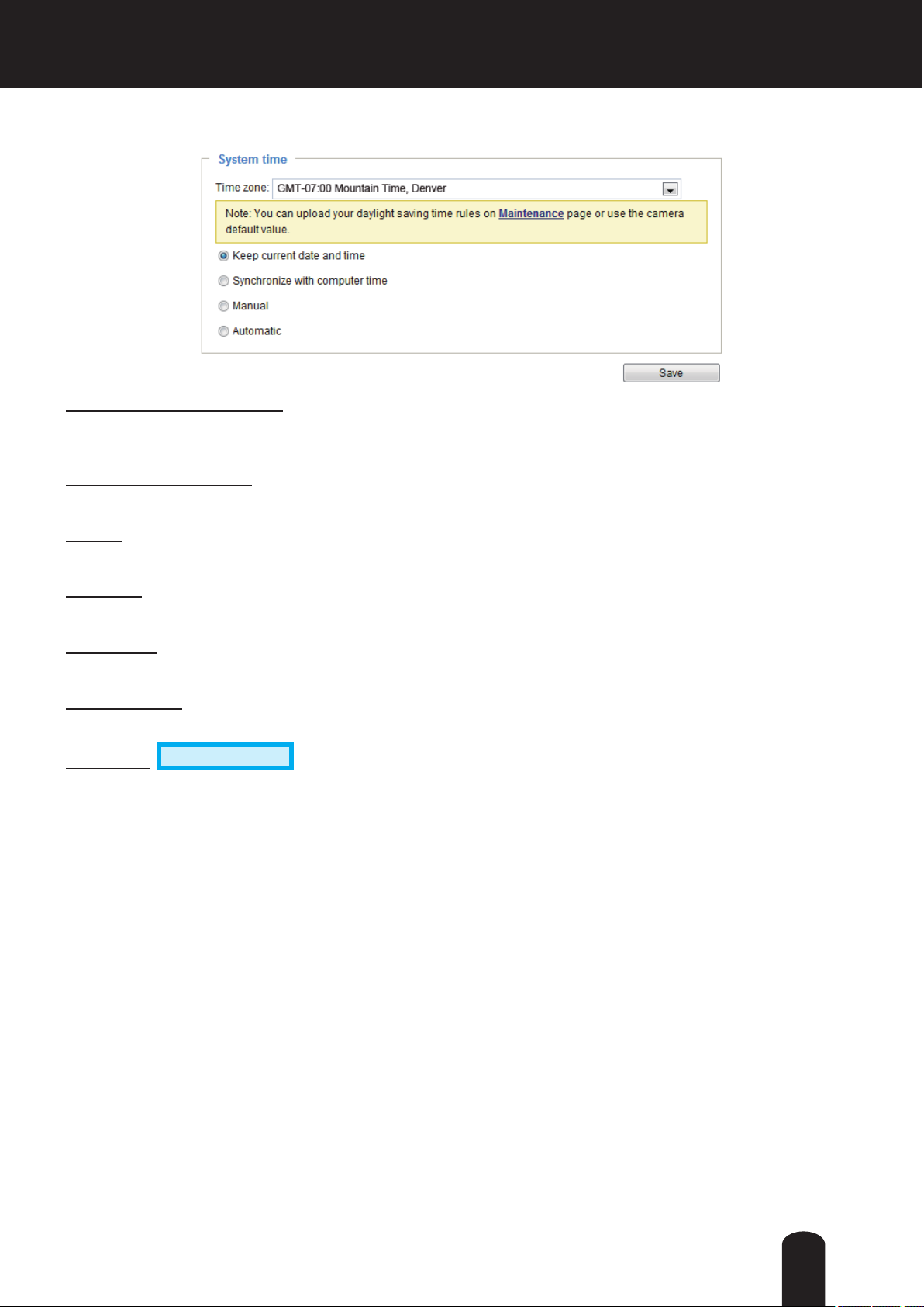
System time
Keep current date and time: Select this option to preserve the current date and time of the Network
Camera. The Network Camera’s internal real-time clock maintains the date and time even when the
power of the system is turned off.
Sync with computer time: Select this option to synchronize the date and time of the Network Camera with
the local computer. The read-only date and time of the PC is displayed as updated.
Manual: The administrator can enter the date and time manually. Note that the date and time format are
[yyyy/mm/dd] and [hh:mm:ss].
Automatic: The Network Time Protocol is a protocol which synchronizes computer clocks by periodically
querying an NTP Server.
NTP server: Assign the IP address or domain name of the time-server. Leaving the text box blank
connects the Network Camera to the default time servers.
Update interval: Select to update the time using the NTP server on an hourly, daily, weekly, or monthly
basis.
Time zone
Daylight Savings Time rules, please refer to System > Maintenance > Import/ Export les on page 40
for details.
When nished with the settings on this page, click Save at the bottom of the page to enable the settings.
Advanced Mode
: Select the appropriate time zone from the list. If you want to upload
33

System > Homepage layout
Advanced Mode
This section explains how to set up your own customized homepage layout.
General settings
This column shows the settings of your hompage layout. You can manually select the background and
font colors in Theme Options (the second tab on this page). The settings will be displayed automatically
in this Preview eld. The following shows the homepage using the default settings:
Logo graph
Here you can change the logo at the top of your homepage.
Follow the steps below to upload a new logo:
1. Click Custom and the Browse eld will appear.
2. Select a logo from your les.
3. Click Upload to replace the existing logo with a new one.
4. Enter a website link if necessary.
5. Click Save to enable the settings.
Customized button
If you want to hide manual trigger buttons on the homepage, please uncheck this item. This item is
checked by default.
34

Theme Options
Here you can change the color of your homepage layout. There are three types of preset patterns for you
to choose from. The new layout will simultaneously appear in the Preview led. Click Save to enable the
settings.
Font Color of the
Video Title
Font Color
Background Color of the
Background Color of the
Configuration Area
Control Area
Font Color of the
Configuration Area
Preset patterns
Background Color of
the Video Area
Frame Color
35
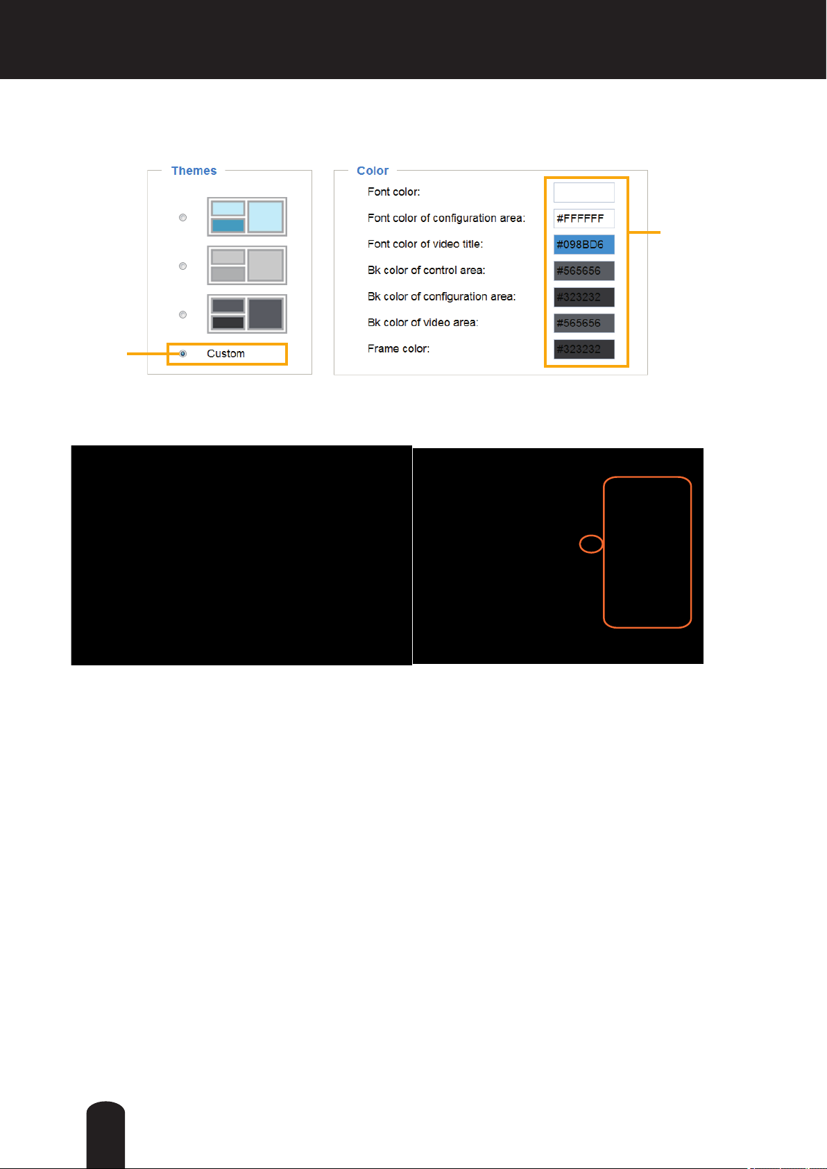
■ Follow the steps below to set up a custom homepage:
1. Click Custom on the left column.
2. Click to select a color on on the right column.
Custom
Pattern
3. The palette window will pop up as shown below.
Color Selector
2
1
4
4. Drag the slider bar and click on the left square to select a desired color.
5. The selected color will be displayed in the corresponding elds and in the Preview column.
6. Click Save to enable the settings.
3
36
System > Logs
Advanced Mode
This section explains how to configure the Network Camera to backup the system log to a
remote server.
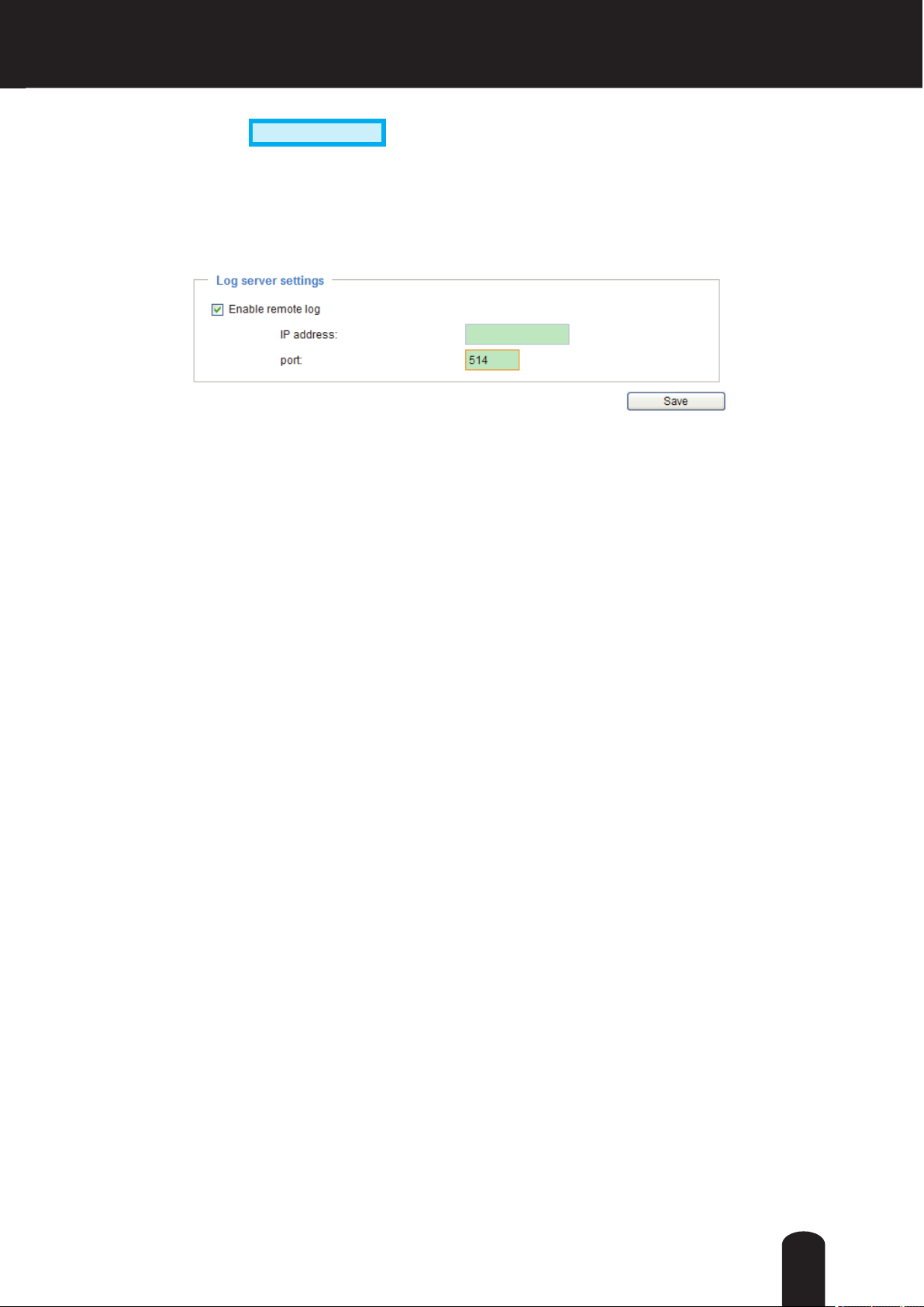
Log server settings
Follow the steps below to set up the remote log:
1. Select Enable remote log.
2. In the IP address text box, enter the IP address of the remote server.
2. In the port text box, enter the port number of the remote server.
3. When completed, click Save to enable the setting.
You can congure the Network Camera to send the system log le to a remote server as a log message.
When using this feature, the appropriate syslog server is required for receiving the system log message
from the Network Camera.
System log
This column displays the system log in chronological order. The system log is stored in the Network
Camera’s buffer and dated events will be overwritten when the number of events reaches a limit.
The system log messages stored in the Network Camera will be all cleared after reboot or power down
the Network Camera.
37

Access log
Access log displays the access time and IP address of all viewers (including operators and
administrators) in chronological order. The access log is stored in the Network Camera’s buffer and older
events will be overwritten when the number of events reaches a limit.
The access log messages stored in the Network Camera will be all cleared after reboot or power down
the Network Camera.
System > Parameters
Advanced Mode
The View Parameters page lists the entire system’s parameters in an alphabetical order. If you
need technical assistance, please provide the information listed on this page.
38
System > Maintenance
This chapter explains how to restore the Network Camera to factory default, upgrade rmware
version, etc.
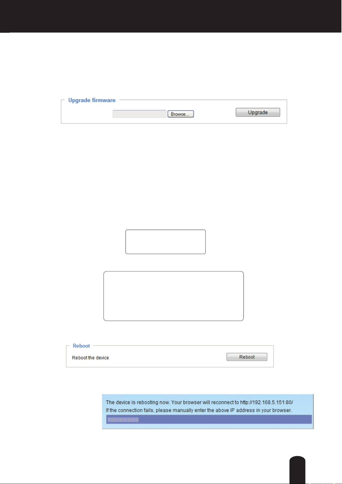
General settings > Upgrade rmware
Firmware file:
This feature allows you to upgrade the firmware of your Network Camera. It takes a few minutes to
complete the process.
Note: Do not power off the Network Camera during the upgrade!
Follow the steps below to upgrade the rmware:
1. Download the latest rmware le from the TOSHIBA website. The le is in .pkg le format.
2. Click Browse… and specify the rmware le.
3. Click Upgrade. The Network Camera starts to upgrade and will reboot automatically when the upgrade
completes.
If the upgrade is successful, you will see “Reboot system now!! This connection will close”. After that, reaccess the Network Camera.
The following message is displayed when the upgrade has succeeded.
Reboot system now!!
This connection will close.
The following message is displayed when you have selected an incorrect rmware le.
Starting firmware upgrade...
Do not power down the server during the upgrade.
The server will restart automatically after the upgrade is
completed.
This will take about 1 - 5 minutes.
Invalid firmware version
Unpack fail...system is rebooting...
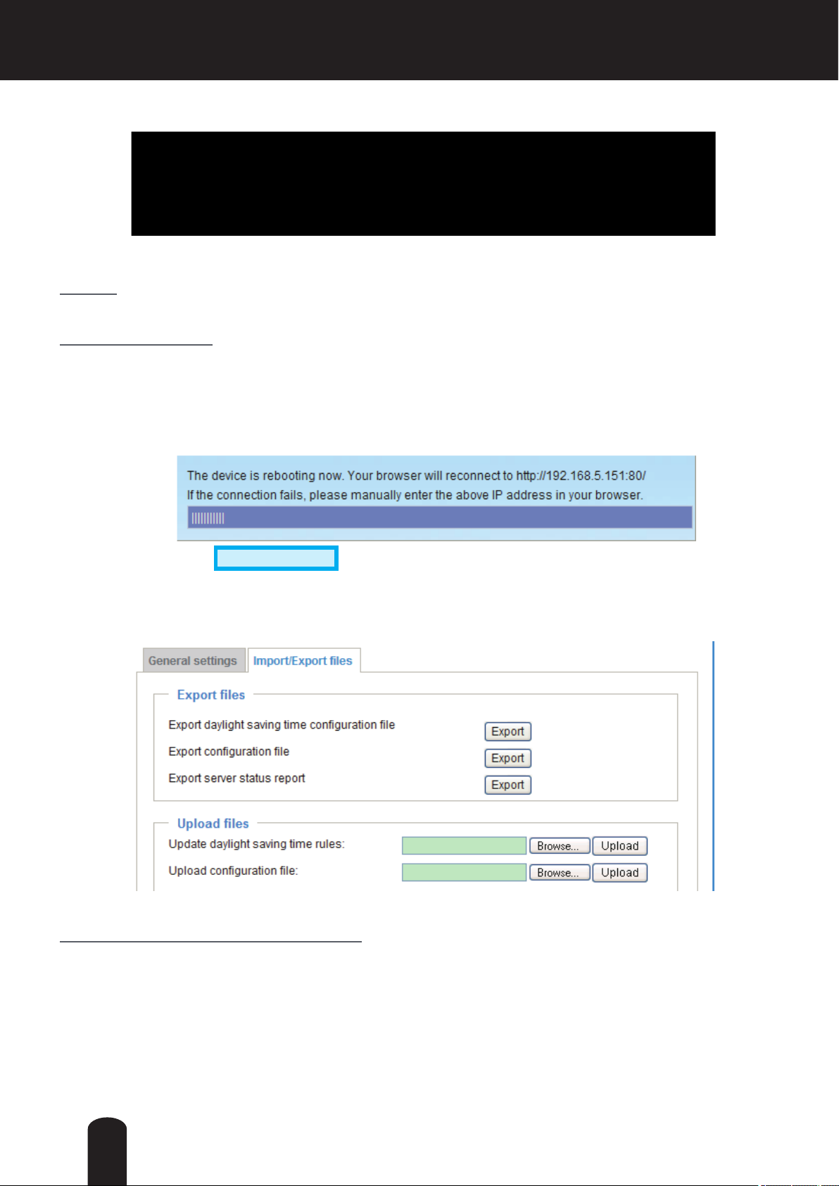
General settings > Reboot
This feature allows you to reboot the Network Camera, which takes about one minute to complete. When
completed, the live video page will be displayed in your browser. The following message will be displayed
during the reboot process.
If the connection fails after rebooting, manually enter the IP address of the Network Camera in the
address eld to resume the connection.
39
General settings > Restore
This feature allows you to restore the Network Camera to factory default settings.
Network: Select this option to retain the Network Type settings (please refer to Network Type on page
54).
Daylight Saving Time: Select this option to retain the Daylight Saving Time settings (please refer to
Import/Export les below on this page).
If none of the options is selected, all settings will be restored to factory default. The following message is
displayed during the restoring process.
Import/Export les
This feature allows you to Export / Update daylight saving time rules, custom language file, and
conguration le.
Export daylight saving time conguration le: Click to set the start and end time of DST.
Advanced Mode
Follow the steps below to export:
1. In the Export les column, click Export to export the daylight saving time conguration le from the
Network Camera.
2. A le download dialog will pop up as shown below. Click Open to review the XML le or click Save to
store the le for editing.
40

3. Open the le with text editor and locate your time zone; set the start and end time of DST. When
completed, save the le.
In the example below, DST begins each year at 2:00 a.m. on the second Sunday in March and ends at
2:00 a.m. on the rst Sunday in November.
Update daylight saving time rules: Click Browse… and specify the XML le to update.
If incorrect date and time are assigned, you will see the following warning message when uploading the
le to the Network Camera.
41

The following message is displayed when attempting to upload an incorrect le format.
Export conguration le: Click to export all parameters for the device and user-dened scripts.
Update conguration le: Click Browse… to update a conguration le. Please note that the model and
rmware version of the device should be the same as the conguration le. If you have set up a xed IP
or other special settings for your device, it is not suggested to update a conguration le.
Export server staus report: Click to export the current server status report, such as time, logs,
parameters, process status, memory status, le system status, network status, kernel message..., and so
on.
42
Security > User Account
This section explains how to enable password protection and create multiple accounts.
Root Password
The administrator account name is “root”, which is permanent and can not be deleted. If you want to add
more accounts in the Manage User column, please apply the password for the “root” account rst.
1. Type the password identically in both text boxes, then click Save to enable password protection.
2. A window will prompt for authentication; type the correct user’s name and password in their respective
elds to access the Network Camera.
Manage Privilege
Digital Output & PTZ control: You can modify the management privilege as operators or viewers. Select
or de-select the checkboxes, and then click Save to enable the settings. If you give Viewers the privilege,
Operators will also have the ability to control the Network Camera through the main page. (Please refer
to Conguration on page 31).
Allow anonymous viewing for 3GPP-compatible mobile devices: If you check this item, 3GPP clients can
access the live stream without entering a User ID and Password.
Note:
* Select RTSP Streaming Authentication to disable.
* This function will not work with Internet Explorer.
Advanced Mode
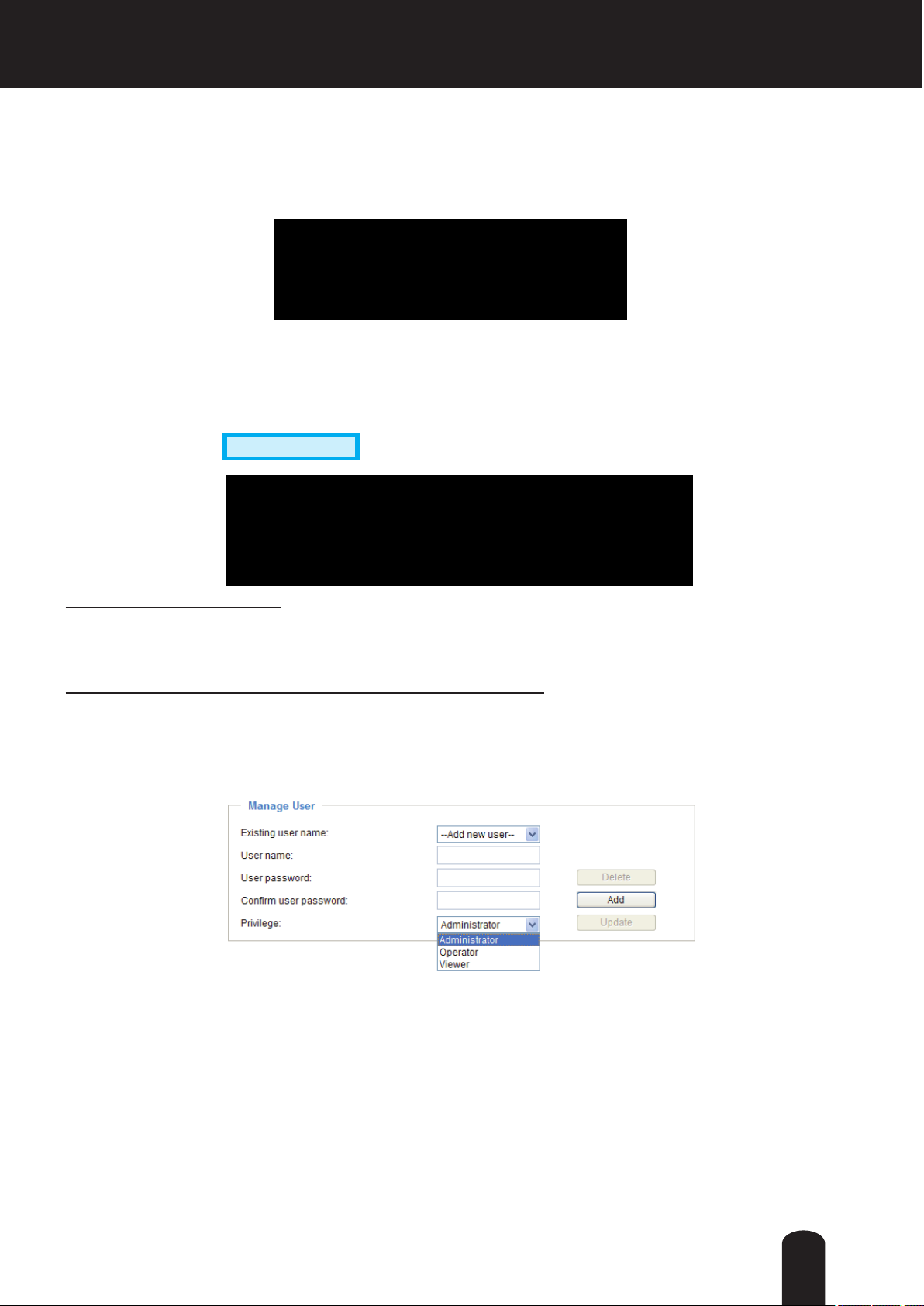
Manage User
Administrators can create up to 20 user accounts.
1. Input the new user’s name and password.
2. Select the privilege level for the new user account. Click Add to enable the setting.
Access rights are sorted by user privilege (Administrator, Operator, and Viewer). Only administrators can
access the Conguration page. Though operators cannot access the Conguration page, they can use
the URL Commands to get and set the value of parameters. For more information, please refer to URL
Command Guide. Viewers access only the main page for live viewing.
Here you also can change a user’s access rights or delete user accounts.
1. Select an existing account to modify.
2. Make necessary changes and click Update or Delete to enable the setting.
43

Security > HTTPS (Hypertext Transfer Protocol over SSL)
Advanced Mode
This section explains how to enable authentication and encrypted communication over SSL
(Secure Socket Layer). It helps protect streaming data transmission over the Internet on higher
security level.
Create and Install Certicate Method
Before using HTTPS for communication with the Network Camera, a Certicate must be created rst.
There are two ways to create and install a certicate:
Create self-signed certificate
1.Select this option from a pull-down menu.
2. In the rst column, select Enable HTTPS secure connection, then select a connection option: “HTTP
& HTTPS” or “HTTPS only”.
3.Click Create certicate to generate a certicate.
4. The Certicate Information will automatically be displayed as shown below. You can click Certi cate
properties to view detailed information about the certicate.
44

5. Click Home to return to the main page. Change the address from “http://” to “https://“ in the address
https://
bar and press Enter on your keyboard. Some Security Alert dialogs will pop up. Click OK or Yes to
enable HTTPS.
https://192.168.5.151/index.html
2010/09/01 13:49:39
45

Create certificate and install
authority.
1. Select this option from a method pull-down menu.
2. Click Create certicate to generate the certicate.
: Select this option if you want to create a certicate from a certicate
46

3. If you see the following Information bar, click OK and click on the Information bar at the top of the page
to allow pop-ups.
4. The pop-up window shows an example of a certicate request.
5. Look for a trusted certificate authority that issues digital certificates. Enroll the Network Camera.
Wait for the certificate authority to issue a SSL certificate; click Browse... to search for the issued
certicate, then click Upload in the column.
47

NOTE
● 1. How do I cancel the HTTPS settings?
1-1. Click on the Remove certicate button.
1-2. The webpage will redirect to a non-HTTPS page automatically.
● 2. If you want to create and install other certicates, please remove the existing one.
Enable HTTPS
Check this item to enable HTTPS communication, then select a connection option: ”HTTP &
HTTPS” or “HTTPS only”. Note that you have to create and install a certicate rst before
clicking the Save button.
48

Security > Access List
This section explains how to control access permission by verifying the client PC’s IP address.
General Settings
Maximum number of concurrent streaming connection(s) limited to: Simultaneous live viewing for 1~10
clients (including stream 1 to stream 3). The default value is 10. If you modify the value and click Save,
all current connections will be disconnected and automatically attempt to re-link.
View Information: Click this button to display the connection status window showing a list of the current
connections. For example:
Note that only consoles that are currently displaying live streaming will be listed in the View Information
list.
■ IP address: Current connections to the Network Camera.
■ Elapsed time: How much time the client has been at the webpage.
■ User ID: If the administrator has set a password for the webpage, the clients have to enter a user name
and password to access the live video. The user name will be displayed in the User ID column. If the
administrator allows clients to link to the webpage without a user name and password, the User ID
column will be empty.
There are some situations that allow clients access to the live video without a user name and
password:
1. The administrator does not set up a root password. For more information about how to set up a root
password and manage user accounts, please refer to Security > User account on page 43.
2. The administrator has set up a root password, but set RTSP Authentication to “disable“. For more
information about RTSP Authentication, please refer to RTSP Streaming on page 63.
3. The administrator has set up a root password, but allows anonymous viewing. For more information
about Allow Anonymous Viewing, please refer to page 43.
49
■ Refresh: Click this button to refresh all current connections.
■ Add to deny list: You can select entries from the Connection Status list and add them to the Deny List
to deny access. Please note that those checked connections will only be disconnected temporarily
and will automatically try to re-link again (IE Explore or Quick Time Player). If you want to enable the
denied list, please check Enable access list ltering and click Save in the rst column.
■ Disconnect: If you want to break off the current connections, please select them and click this
button. Please note that those checked connections will only be disconnected temporarily and will
automatically try to re-link again (IE Explore or Quick Time Player).
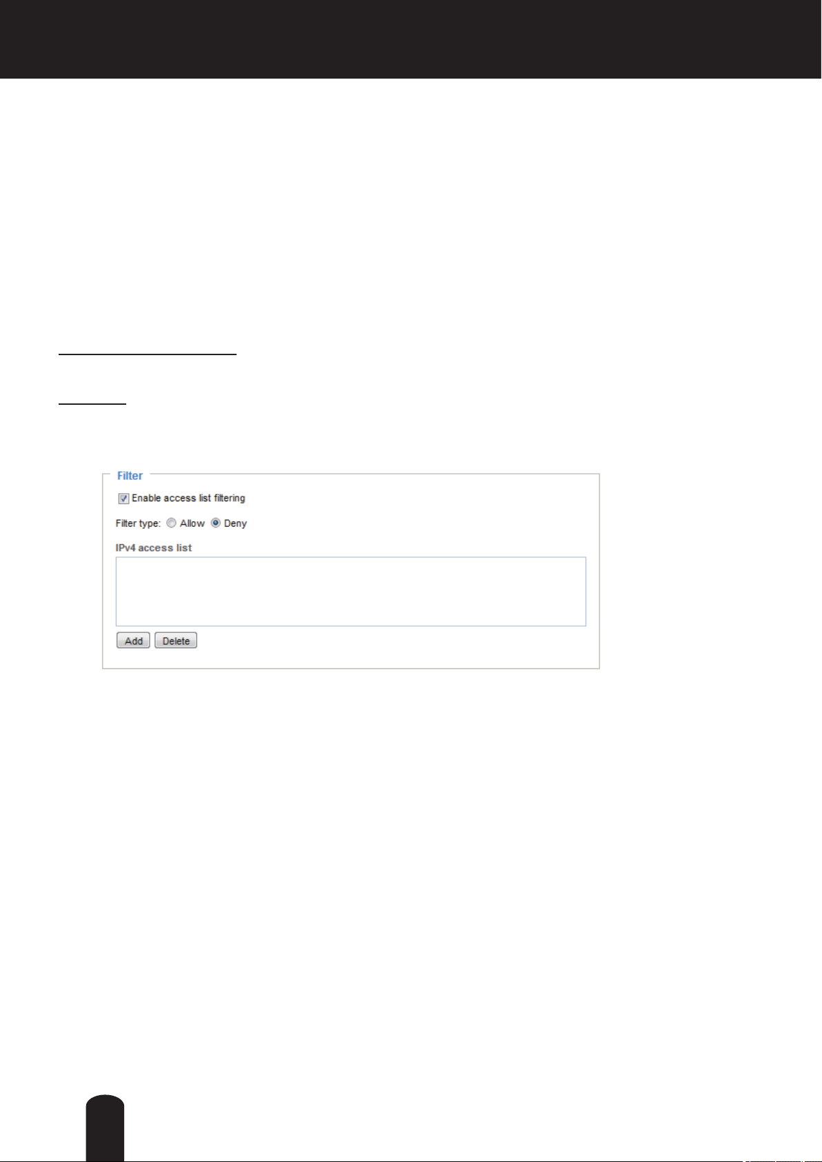
Filter
Enable access list ltering: Check this item and click Save if you want to enable the access list ltering
function.
Filter type: Select Allow or Deny as the lter type. If you choose Allow Type, only those clients whose
IP addresses are on the Access List below can access the Network Camera, and the others cannot. On
the contrary, if you choose Deny Type, those clients whose IP addresses are on the Access List below
will not be allowed to access the Network Camera, and the others access.
Then you can Add a rule to the following Access List. Please note that the IPv6 access list column
will not be displayed unless you enable IPv6 on the Network page. For more information about IPv6
Settings, please refer to Network > General settings on page 54 for detailed information.
50

There are three types of rules:
Single: This rule allows the user to add an IP address to the Allowed/Denied list.
For example:
192.168.2.1
Network: This rule allows the user to assign a network address and corresponding subnet mask to the
Allow/Deny List. The address and network mask are written in CIDR format.
For example:
IP address range 192.168.2.x will be bolcked.
Range: This rule allows the user to assign a range of IP addresses to the Allow/Deny List.
Note: This rule only applies to IPv4 addresses.
For example:
Administrator IP address
Always allow the IP address to access this device: You can check this item and add the Administrator’s
IP address in this eld to make sure the Administrator can always connect to the device.
51
Advanced Mode
Security > IEEE 802.1x
Enable this function if your network environment uses IEEE 802.1x, which is a port-based network
access control. The network devices, intermediary switch/access point/hub, and RADIUS server must
support and enable 802.1x settings.
The 802.1x standard is designed to enhance the security of local area networks, which provides
authentication to network devices (clients) attached to a network port (wired or wireless). If all certicates
between client and server are veried, a point-to-point connection will be enabled; if authentication fails,
access on that port will be prohibited. 802.1x utilizes an existing protocol, the Extensible Authentication
Protocol (EAP), to facilitate communication.
The components of a protected network with 802.1x authentication:
■
Supplicant
(Network Camera)
Supplicant: A client end user (camera), which requests authentication.
1.
Authenticator (an access point or a switch): A “go between” which restricts unauthorized end users
2.
Authenticator
(Network Switch)
Authentication Server
(RADIUS Server)
from communicating with the authentication server.
Authentication server (usually a RADIUS server): Checks the client certicate and decides whether to
3.
accept the end user’s access request.
Network Cameras support two types of EAP methods to perform authentication: EAP-PEAP and EAP-
■
TLS.
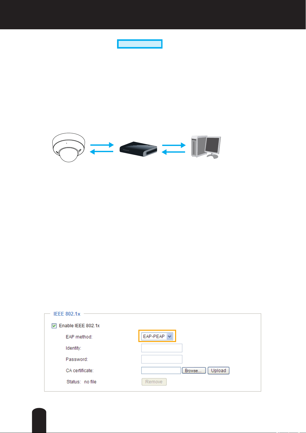
Please follow the steps below to enable 802.1x settings:
1. Before connecting the Network Camera to the protected network with 802.1x, please apply a digital
certicate from a Certicate Authority (ie. MIS of your company) which can be validated by a RADIUS
server.
2. Connect the Network Camera to a PC or notebook outside of the protected LAN. Open the
conguration page of the Network Camera as shown below. Select EAP-PEAP or EAP-TLS as the
EAP method. In the following blanks, enter your ID and password issued by the CA, then upload
related certicate(s).
52

3. When all settings are complete, move the Network Camera to the protected LAN by connecting it to
an 802.1x enabled switch. The devices will then start the authentication automatically.
NOTE
● The maximum length of password is 200 symbols.
● The authentication process for 802.1x:
1. The Certicate Authority (CA) provides the required signed certicates to the Network Camera
(the supplicant) and the RADIUS Server (the authentication server).
2. A Network Camera requests access to the protected LAN using 802.1X via a switch (the
authenticator). The client offers its identity and client certificate, which is then forwarded
by the switch to the RADIUS Server, which uses an algorithm to authenticate the Network
Camera and returns an acceptance or rejection back to the switch.
3. The switch also forwards the RADIUS Server’s certicate to the Network Camera.
4. Assuming all certicates are validated, the switch then changes the Network Camera’s state
to authorized and is allowed access to the protected network via a pre-congured port.
Certificate Authority
1
(CA)
Certificate
1
Certificate
Network Camera
2
4
Network Switch
Protected LAN
RADIUS Server
3
53

Network > General settings
This section explains how to congure a wired network connection for the Network Camera.
Network Type
LAN
Select this option when the Network Camera is deployed on a local area network (LAN) and is intended
to be accessed by local computers. The default setting for the Network Type is LAN. Rememer to click
Save when you complete the Network setting.
Get IP address automatically: Select this option to obtain an available dynamic IP address assigned by
the DHCP server each time the camera is connected to the LAN.
Use xed IP address: Select this option to manually assign a static IP address to the Network Camera.
1. You can use Installation Wizard on the software CD to easily set up the Network
Camera on LAN. Please refer to Software Installation on page 19 for details.
2. Enter the Static IP, Subnet mask, Default router, and Primary DNS provided by your ISP.
Subnet mask: This is used to determine if the destination is in the same subnet. The default value is
“255.255.255.0”.
Default router: This is the gateway used to forward frames to destinations in a different subnet. Invalid
router setting will fail the transmission to destinations in different subnet.
54

Primary DNS: The primary domain name server that translates hostnames into IP addresses.
Secondary DNS: Secondary domain name server that backups the Primary DNS.
Primary WINS server: The primary WINS server that maintains the database of computer name and IP
address.
Secondary WINS server: The secondary WINS server that maintains the database of computer name
and IP address.
TM
Enable UPnP presentation: Select this option to enable UPnP
presentation for your Network Camera
so that whenever a Network Camera is presented to the LAN, shortcuts of connected Network Cameras
will be listed in My Network Places. You can click the shortcut to link to the web browser. Currently,
TM
UPnP
UPnP
is supported by Windows XP or later. Note that to utilize this feature, please make sure the
TM
component is installed on your computer.
Network Camera (192.168.5.128)
Network Camera (192.168.5.141)
Network Camera (192.168.5.151)
Enable UPnP port forwarding: To access the Network Camera from the Internet, select this option to
allow the Network Camera to open ports on the router automatically so that video streams can be sent
out from a LAN. To utilize of this feature, make sure that your router supports UPnP
TM
and it is activated.
PPPoE (Point-to-point over Ethernet)
Select this option to congure your Network Camera to make it accessible from anywhere as long as
there is an Internet connection. Note that to utilize this feature, it requires an account provided by your
ISP (service provider).
Follow the steps below to acquire your Network Camera’s public IP address.
1. Set up the Network Camera on the LAN.
2. Go to Conguration > Event > Event settings > Add server (please refer to Add server on page 99) to
add a new email or FTP server.
3. Go to Conguration > Event > Event settings > Add media (please refer to Add media on page 104).
Select System log so that you will receive the system log in TXT le format which contains the
Network Camera’s public IP address in your email or on the FTP server.
4. Go to Conguration > Network > General settings > Network type. Select PPPoE and enter the user
name and password provided by your ISP. Click Save to enable the setting.
5. The Network Camera will reboot.
6. Disconnect the power to the Network Camera; remove it from the LAN environment.
55
NOTE
● If the default ports are already used by other devices connected to the same router, the
Network Camera will select other ports for the Network Camera.
● If UPnPTM is not supported by your router, you will see the following message:
Error: Router does not support UPnP port forwarding.
● Below are steps to enable the UPnPTM user interface on your computer:
Note that you must log on to the computer as a system administrator to install the UPnPTM
components.
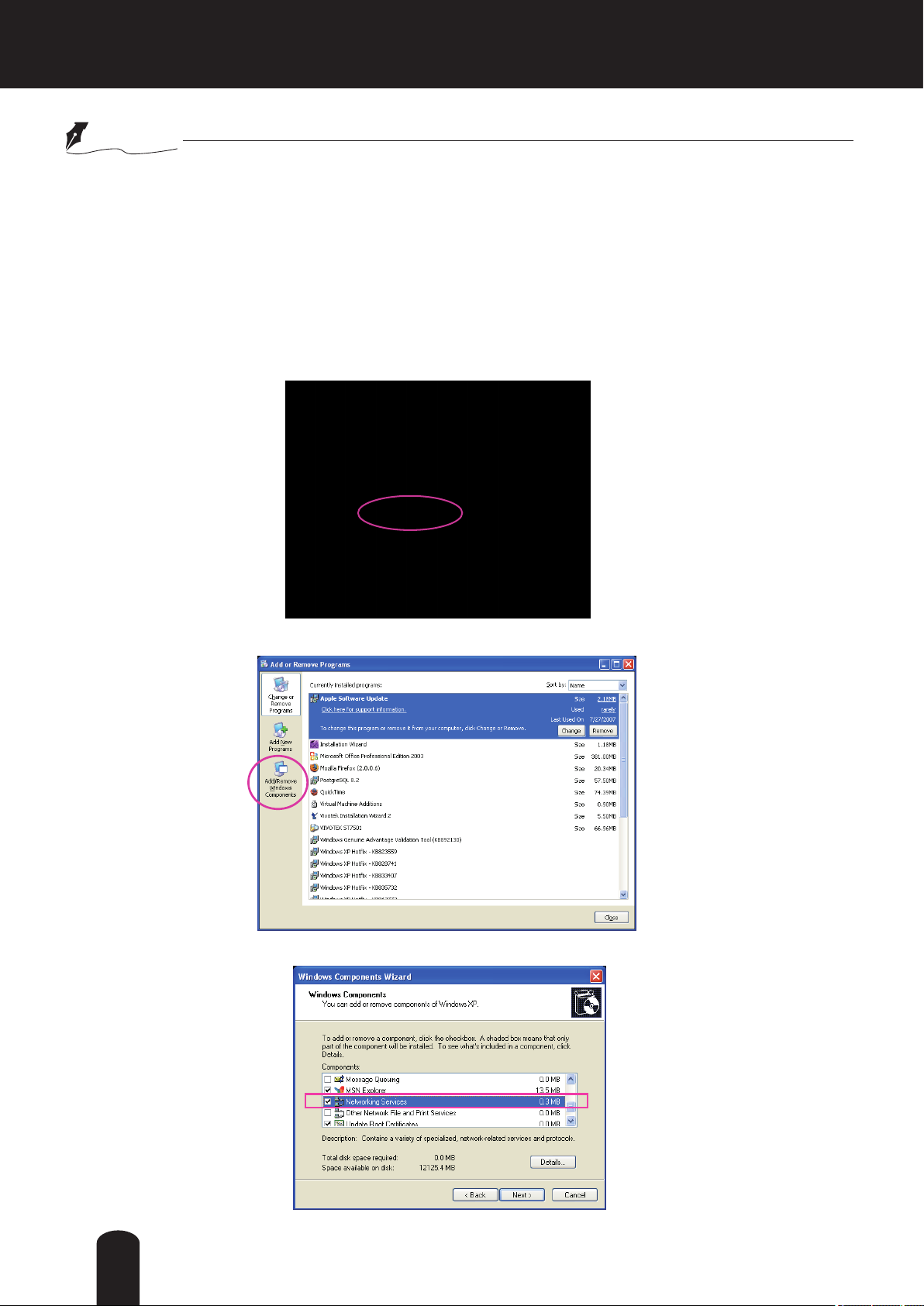
1. Go to Start, click Control Panel, then click Add or Remove Programs.
2. In the Add or Remove Programs dialog box, click Add/Remove Windows Components.
3.
In the Windows Components Wizard dialog box, select Networking Services and click
Details.
56

4. In the Networking Services dialog box, select Universal Plug and Play and click OK.
5. Click Next in the following window.
6. Click Finish. UPnPTM is enabled.
How does UPnPTM work?
●
UPnP
TM
networking technology provides automatic IP conguration and dynamic discovery of
devices added to a network. Services and capabilities offered by networked devices, such as
printing and le sharing, are available among each other without the need for cumbersome
network configuration. In the case of Network Cameras, you will see Network Camera
shortcuts under My Network Places.
●
Enabling UPnP port forwarding allows the Network Camera to open a secondary HTTP port
on the router-not HTTP port-meaning that you have to add the secondary HTTP port number
to the Network Camera’s public address in order to access the Network Camera from the
Internet. For example, when the HTTP port is set to 80 and the secondary HTTP port is set to
8080, refer to the list below for the Network Camera’s IP address.
From the Internet In LAN
http://203.67.124.123:8080 http://192.168.4.160 or
http://192.168.4.160:8080
● If the PPPoE settings are incorrectly congured or the Internet access is not working, restore
the Network Camera to factory default; please refer to Restore on page 40 for details. After
the Network Camera is reset to factory default, it will be accessible on the LAN.
57

Enable IPv6
Select this option and click Save to enable IPv6 settings.
Please note that this only works if your network environment and hardware equipment support IPv6. The
browser should be Microsoft
When IPv6 is enabled, by default, the network camera will listen to router advertisements and be
assigned with a link-local IPv6 address accordingly.
®
Internet Explorer 6.5 or above.
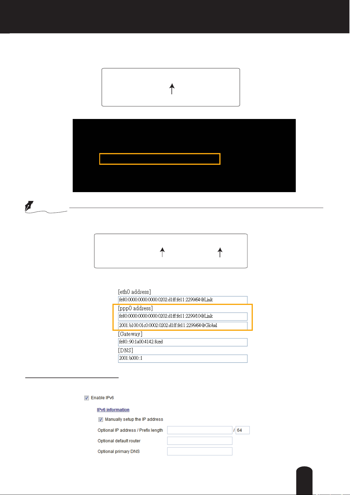
IPv6 Information: Click this button to obtain the IPv6 information as shown below.
If your IPv6 settings are successful, the IPv6 address list will be listed in the pop-up window. The IPv6
address will be displayed as follows:
Refers to Ethernet
Link-global IPv6 address/network mask
Link-local IPv6 address/network mask
58
Please follow the steps below to link to an IPv6 address:
1. Open your web browser.
2. Enter the link-global or link-local IPv6 address in the address bar of your web browser.
3. The format should be:
http://[2001:0c08:2500:0002:0202:d1ff:fe04:65f4]/
IPv6 address
4. Press Enter on the keyboard or click Refresh button to refresh the webpage.
For example:
NOTE
If you have a Secondary HTTP port (the default value is 8080), you can also link to the webpage in
●
the following address format: (Please refer to HTTP streaming on page 62 for detailed information.)
http://[2001:0c08:2500:0002:0202:d1ff:fe04:65f4]/:8080
IPv6 address
If you choose PPPoE as the Network Type, the [PPP0 address] will be displayed in the IPv6
●
Secondary HTTP port
information column as shown below.
Manually setup the IP address: Select this option to manually set up IPv6 settings if your network
environment does not have DHCPv6 server and router advertisements-enabled routers.
If you check this item, the following blanks will be displayed for you to enter the corresponding
information:
59

Port
HTTPS port: By default, the HTTPS port is set to 443. It can also be assigned to another port number
between 1025 and 65535.
Two way audio port: By default, the two way audio port is set to 5060. Also, it can also be assigned to
another port number between 1025 and 65535.
The Network Camera supports two way audio communication so that operators can transmit and receive
audio simultaneously. By using the Network Camera’s built-in or external microphone and an external
speaker, you can communicate with people around the Network Camera.
Note that as JPEG only transmits a series of JPEG images to the client, to enable the two-way audio
function, make sure the video mode is set to H.264 on the Audio and Video > Stream > Stream settings
page and the media option is set to "Video and Audio" on the Client Settings page. Please refer to Client
Settings on page 29 and Stream settings on page 81.
Audio transmitted to operators
Audio transmitted from operators
60

Audio is being transmitted to the Network Camera
Video (TCP-AV)
Talk Button
Mic Volume
2011/03/09 17:08:56
Mute
Click to enable audio transmission to the Network Camera; click to adjust the volume of
microphone; click
to turn off the audio. To stop talking, click again.
FTP port: The FTP server allows the user to save recorded video clips. You can use TOSHIBA Installation
Wizard software to upgrade the rmware via FTP server. By default, the FTP port is set to 21. It also can
be assigned to another port number between 1025 and 65535.
61

Network > Streaming protocols
Advanced Mode
HTTP streaming
To utilize HTTP authentication, make sure that your have set a password for the Network Camera rst;
please refer to Security > User account on page 43 for details.
Authentication: Depending on your network security requirements, the Network Camera provides two
types of security settings for an HTTP transaction: basic and digest.
If basic authentication is selected, the password is sent in plain text format and there can be potential
risks of being intercepted. If digest authentication is selected, user credentials are encrypted using MD5
algorithm and thus provide better protection against unauthorized accesses.
HTTP port / Secondary HTTP port: By default, the HTTP port is set to 80 and the secondary HTTP port is
set to 8080. They can also be assigned to another port number between 1025 and 65535. If the ports are
incorrectly assigned, the following warning messages will be displayed:
To access the Network Camera on the LAN, both the HTTP port and secondary HTTP port can be used
to access the Network Camera. For example, when the HTTP port is set to 80 and the secondary HTTP
port is set to 8080, refer to the list below for the Network Camera’s IP address.
On the LAN
http://192.168.4.160 or
http://192.168.4.160:8080
Access name for stream 1 ~ 3: This Network camera supports multiple streams simultaneously. The
access name is used to differentiate the streaming source. Users can click Audio and Video > Stream >
Stream settings to set up the video quality of linked streams. For more information about how to set up
the video quality, please refer to Stream settings on page 81.
62

RTSP Streaming
To utilize RTSP streaming authentication, make sure that you have set a password for the Network
Camera rst; please refer to Security > User account on page 43 for details.
63

Authentication: Depending on your network security requirements, the Network Camera provides three
types of security settings for streaming via RTSP protocol: disable, basic, and digest.
If basic authentication is selected, the password is sent in plain text format, but there can be potential
risks of it being intercepted. If digest authentication is selected, user credentials are encrypted using
MD5 algorithm, thus providing better protection against unauthorized access.
Access name for stream 1 ~ 3: This Network camera supports multiple streams simultaneously. The
access name is used to differentiate the streaming source.
If you want to use an RTSP player to access the Network Camera, you have to set the video mode to
H.264 and use the following RTSP URL command to request transmission of the streaming data.
rtsp://<ip address>:<rtsp port>/<access name for stream1 ~ 3>
For example, when the access name for stream 1 is set to live.sdp:
1. Launch an RTSP player.
2. Choose File > Open URL. A URL dialog box will pop up.
3. Type the above URL command in the address eld.
4. The live video will be displayed in your player.
rtsp://192.168.5.151:554/live.sdp
RTSP port /RTP port for video, audio/ RTCP port for video, audio
■ RTSP (Real-Time Streaming Protocol) controls the delivery of streaming media. By default, the port
number is set to 554.
■ The RTP (Real-time Transport Protocol) is used to deliver video and audio data to the clients. By
default, the RTP port for video is set to 5556 and the RTP port for audio is set to 5558.
■ The RTCP (Real-time Transport Control Protocol) allows the Network Camera to transmit the data by
monitoring the Internet trafc volume. By default, the RTCP port for video is set to 5557 and the RTCP
port for audio is set to 5559.
The ports can be changed to values between 1025 and 65535. The RTP port must be an even number
and the RTCP port is the RTP port number plus one, and thus is always an odd number. When the RTP
port changes, the RTCP port will change accordingly.
If the RTP ports are incorrectly assigned, the following warning message will be displayed:
64

Multicast settings for stream 1 ~ 3: Click the items to display the detailed configuration information.
Select the Always multicast option to enable multicast for stream 1 ~ 3.
Unicast video transmission delivers a stream through point-to-point transmission; multicast, on the other
hand, sends a stream to the multicast group address and allows multiple clients to acquire the stream at
the same time by requesting a copy from the multicast group address. Therefore, enabling multicast can
effectively save Internet bandwith.
The ports can be changed to values between 1025 and 65535. The multicast RTP port must be an even
number and the multicast RTCP port number is the multicast RTP port number plus one, and thus is
always odd. When the multicast RTP port changes, the multicast RTCP port will change accordingly.
If the multicast RTP video ports are incorrectly assigned, the following warning message will be
displayed:
Multicast TTL [1~255]: The multicast TTL (Time To Live) is the value that tells the router the range a
packet can be forwarded.
Initial TTL Scope
0 Restricted to the same host
1 Restricted to the same subnetwork
32 Restricted to the same site
64 Restricted to the same region
128 Restricted to the same continent
255 Unrestricted in scope
65

Network > DDNS
This section explains how to configure the dynamic domain name service for the Network
Camera. DDNS is a service that allows your Network Camera, especially when assigned with a
dynamic IP address, to have a xed host and domain name.
DDNS: Dynamic domain name service
Enable DDNS: Select this option to enable the DDNS setting.
Provider: The provider list contains seven hosts that provide DDNS service. Please connect to the
service provider’s web site to review the service charges and sign-up for the service if you want to use
DDNS.
ChangeIP.com
http://www.changeip.com/toshiba/
No-IP.com
http://www.no-ip.com/ext/toshiba.php
Host Name: If the User wants to use a DDNS service, enter the camera name that is registered at the
DDNS server.
User Name: The User Name eld is necessary for logging into the DDNS server or to notify the User of
the new IP address.
Note: When this eld is input as “User Name”, the following eld nust be input as “Password”.
Password: Input the password to access the DDNS service.
Save: Click on this button to save current settings for the DDNS service.
66
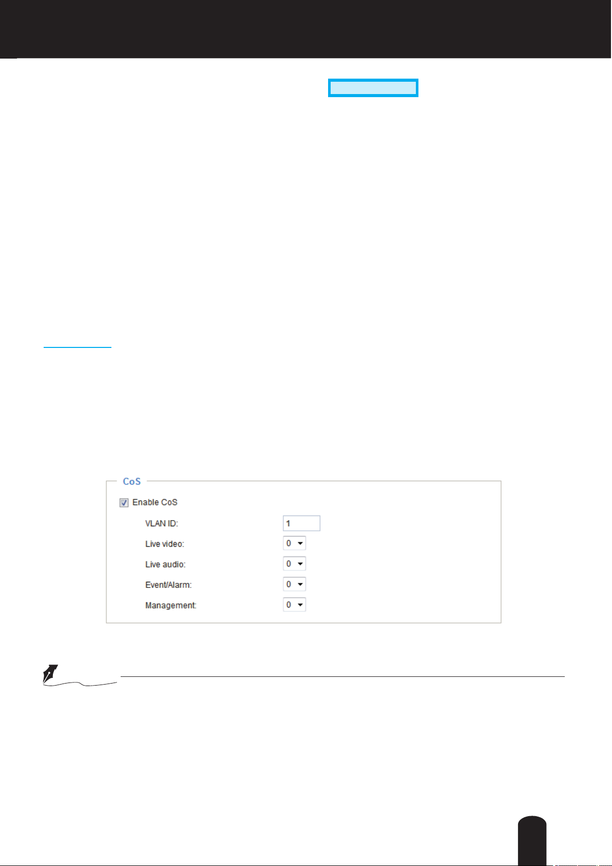
Advanced Mode
Network > QoS (Quality of Service)
Quality of Service refers to a resource reservation control mechanism, which guarantees a certain quality
to different services on the network. Quality of service guarantees are important if the network capacity
is insufcient, especially for real-time streaming multimedia applications. Quality can be dened as, for
instance, a maintained level of bit rate, low latency, no packet dropping, etc.
The following are the main benets of a QoS-aware network:
The ability to prioritize trafc and guarantee a certain level of performance to the data ow.
■
The ability to control the amount of bandwidth each application may use, and thus provide higher
■
reliability and stability on the network.
Requirements for QoS
To utilize QoS in a network environment, the following requirements must be met:
All network switches and routers in the network must include support for QoS.
■
The network video devices used in the network must be QoS-enabled.
■
QoS models
CoS (the VLAN 802.1p model)
IEEE802.1p defines a QoS model at OSI Layer 2 (Data Link Layer), which is called CoS, Class of
Service. It adds a 3-bit value to the VLAN MAC header, which indicates the frame priority level from 0
(lowest) to 7 (highest). The priority is set up on the network switches, which then use different queuing
disciplines to forward the packets.
Below is the setting column for CoS. Enter the VLAN ID of your switch (0~4095) and choose the priority
for each application (0~7).
If you assign Video the highest priority level, your network switch will handle video packets rst.
NOTE
● A VLAN Switch (802.1p) is required. Web browsing may fail if the CoS setting is incorrect.
●
Class of Service technologies do not guarantee a level of service in terms of bandwidth and
delivery time; they offer a “best-effort.” Users can think of CoS as “coarsely-grained” traffic
control and QoS as “nely-grained” trafc control.
Though CoS is simple to manage, it lacks scalability and does not offer end-to-end guarantees
●
since it is based on L2 protocol.
67

QoS/DSCP (the DiffServ model)
DSCP-ECN defines QoS at Layer 3 (Network Layer). The Differentiated Services (DiffServ) model is
based on packet marking and router queuing disciplines. The marking is done by adding a eld to the
IP header, called the DSCP (Differentiated Services Codepoint). This is a 6-bit field that provides 64
different class IDs. It gives an indication of how a given packet is to be forwarded, known as the Per Hop
Behavior (PHB). The PHB describes a particular service level in terms of bandwidth, queueing theory,
and dropping (discarding the packet) decisions. Routers at each network node classify packets according
to their DSCP value and give them a particular forwarding treatment; for example, how much bandwidth
to reserve for it.
Below are the setting options of DSCP (DiffServ Codepoint). Specify the DSCP value for each application
(0~63).
68

Network > SNMP (Simple Network Management Protocol)
Advanced Mode
This section explains how to use the SNMP on the network camera. The Simple Network
Management Protocol is an application layer protocol that facilitates the exchange of
management information between network devices. It helps network administrators to remotely
manage network devices and nd, solve network problems with ease.
■ The SNMP consists of the following three key components:
1. Manager: Network-management station (NMS), a server which executes applications that monitor and
control managed devices.
2. Agent: A network-management software module on a managed device which transfers the status of
managed devices to the NMS.
3. Managed device: A network node on a managed network. For example: routers, switches, bridges,
hubs, computer hosts, printers, IP telephones, network cameras, web server, and database.
Before conguring SNMP settings on the this page, please enable your NMS rst.
SNMP Conguration
Enable SNMPv1, SNMPv2c
Select this option and enter the names of Read/Write community and Read Only community according to
your NMS settings.
Enable SNMPv3
This option contains cryptographic security, a higher security level, which allows you to set the
Authentication password and the Encryption password.
■ Security name: According to your NMS settings, choose Read/Write or Read Only and enter the
community name.
■ Authentication type: Select MD5 or SHA as the authentication method.
■ Authentication password: Enter the password for authentication (at least 8 characters).
■ Encryption password: Enter a password for encryption (at least 8 characters).
69

Audio and Video > Image
Advanced Mode
This section explains how to congure the image settings of the Network Camera. It is composed of the
following four columns: General settings, Preference, Exposure, Zoom and Focus, and Privacy mask.
General settings
Video title: Enter a name that will be displayed on the title bar of the live video as the picture shown
below.
Show timestamp and video title in video and snapshots: Enter a name that will be displayed on the title
bar of the live video as the picture shown below.
Zoom factor: If you check this item, the zoom indicator will be displayed on the live view window when
you operating digital-zoom in/out. You may zoom in/out the image by scrolling the mouse inside the live
viewing window, or click the zoom button on main page.
Position of timestamp and video title on image: Select to display time stamp and video title on the top or
at the bottom of the video stream.
Timestamp and video title font size: Select the font size for the time stamp and title.
Video Title
Title and Time
Video (TCP-AV)
Video 17:08:56 2011/10/15
2011/10/15 17:08:56
Color: Select to display color or black/white video streams.
Power line frequency: Set the power line frequency consistent with local utility settings to eliminate image
flickering associated with fluorescent lights. Note that after the power line frequency is changed, you
must disconnect and reconnect the power cord of the Network Camera in order for the new setting to
take effect.
70
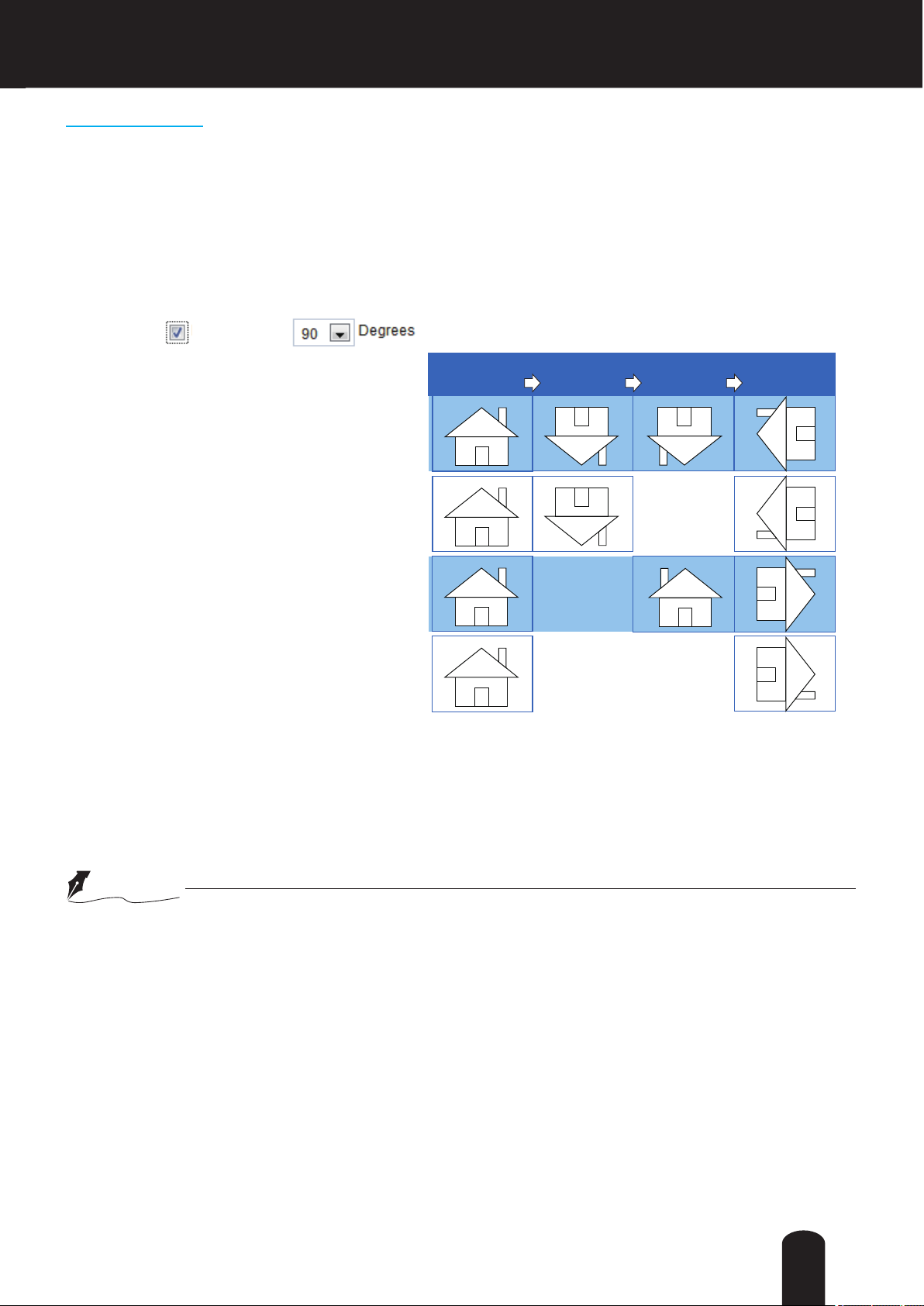
Video orientation:
Flip - vertically reect the display of the live video;
Mirror - horizontally reect the display of the live video. Select both options if the Network Camera is
installed upside-down (e.g., on the ceiling) to correct the image orientation. Please note that if you have
preset locations, those locations will be cleared after ip/mirror setting.
Hallway View-
Hallway View
MirrorNormal Flip Rotate 90°
Hallway view indicates clockwise rotation.
clockwise
Hallway view can be applied with ip, mirror,
and physical lens rotation (image orientation)
sett i ngs to adapt to di fferent mounti ng
locations.
The conventional HD image, such as that of
a 16:9 aspect ratio, will be incongruous with
its wide horizontal view at hallways, aisles,
tunnels and many other applications. With
video rotation, such as that of a 9:16 aspect
ratio, the camera can make effective use of
sensor resolution and bandwidth.
The gures in the illustration are shown in a
consecutive order.
When you install a camera in a hallway, rotate a lens 90 degrees by physical lens rotation (3-axis) of a
camera after securing on the ceiling.
After that, rotate an image 90 or 270 degrees by this function.
NOTE
Applying this function will consume processor resource, maximum frame rate will reduce by 30%.
●
71

Day/Night Settings
Switch to B/W in night mode
Select this checkbox to enable the Network Camera to automatically switch to Black & White display
during the night mode.
Turn on external IR illuminator in night mode
Select this to turn on an external IR illuminator (connected via Digital Output lines) when the camera
detects low light condition and enters the night mode.
Turn on built-in IR illuminator in night mode
Select this to turn on the built-in IR illuminators when the camera detects low light condition and enters
the night mode.
Adaptive IR
When enabled, the camera automatically adjust the IR projection to adjacent objects in order to avoid
over-exposure in the night mode.
The Adaptive IR function is more benecial when the spot of intrusions or an object of your interest is
close to the lens and the IR lights. For example, if an intruder has a chance of getting near the range
of 3 meters, Adaptive IR can effectively reduce the over-exposure. For a surveillance area at a greater
distance, e.g., 5 meters, the Adaptive IR function may not bring as signicant benets as in close range.
IR cut lter
With a removable IR-cut lter, this Network Camera can automatically remove the lter to let Infrared light
pass into the sensor during low light conditions.
■ Auto mode
The Network Camera automatically removes the lter by judging the level of ambient light.
■ Day mode
In day mode, the Network Camera switches on the IR cut lter at all times to block infrared light from
reaching the sensor so that the colors will not be distorted.
■ Night mode
In night mode, the Network Camera switches off the IR cut lter at all times for the sensor to accept
infrared light, thus helping to improve low light sensitivity.
■ Synchronize with digital input
The Network Camera automatically removes the IR cut lter when DI triggers.
■ Schedule mode
The Network Camera switches between day mode and night mode based on a specied schedule.
Enter the start and end time for day mode. Note that the time format is [hh:mm] and is expressed in
24-hour clock time. By default, the start and end time of day mode are set to 07:00 and 18:00.
Light sensor sensitivity
Select Low, Medium, or High sensitivity for the light sensor.
NOTE
When completed with the settings on this page, click Save to enable the settings.
●
72

Preference
On this page, you can tune the White balance, Image adjustment and 3D Noise reduction parameters.
You can configure two sets of preferred settings: one for normal situations, the other for special
situations, such as day/night/schedule mode.
Sensor Setting 1:
For normal situations
White balance: Adjust the value for the best color temperature.
■ Auto: It will automatically adjust the color temperature of the light in response to different light sources.
You may follow the steps below to adjust the white balance to the best color temperature.
1. Set the White balance to Auto.
2. Place a sheet of white paper in front of the lens, then allow the Network Camera to adjust the color
temperature automatically.
3. Click the On button of Fix current value and conrm the setting while the white balance is being
measured.
■ Manual: This item allows users to manually tune the R gain & B gain ratios.
Image Adjustment
■ Brightness: Adjust the image brightness level, which ranges from 0% to 100%.
■
Contrast: Adjust the image contrast level, which ranges from 0% to 100%.
■ Saturation: Adjust the image saturation level, which ranges from 0% to 100%.
■ Sharpness: Adjust the image sharpness level, which ranges from 0% to 100%.
■ Gamma curve: Select the Optimize mode. Or select the Manual mode, and pull the slide bar pointer
to change the preferred level of Gamma correction towards higher contrast or towards the higher
luminance for detailed expression for both dark and lighted areas of an image.
73

■ Enable low light compensation: Select this option in low light mode, and the values of sharpness and
brightness will change automatically as the noise reduction function.
NOTE: Sharpness may be temporarily emphasized as it becomes dark.
3D noise reduction
■ Enable 3DNR: Check to enable 3DNR in order to reduce noises and ickers in image. Use the pull-
down menu to adjust the reduction strength.
NOTE
Applying this function will consume processor resource, maximum frame rate will reduce by half.
●
3D Noise Reduction is mostly applied in low-light conditions. On the other hand, when enabled in a
●
low-light condition with fast moving objects, trails of after-images may occur. You may then select a
lower strength level or disable the function.
When completed with the settings on this page, click Save to enable the settings.
●
74

If you want to congure another sensor setting for day/night/schedule mode, please click Prole to open
the Prole Settings page as shown below.
Please follow the steps below to setup a prole:
1. Check Enable and apply this prole.
2. Select the applied mode: Day mode, Night mode, or Schedule mode. Please manually enter a range of
time if you choose Schedule mode.
3. Configure the settings in the following columns. Please refer to the previous page for detailed
information.
4. Click Save to enable the settings and click Close to exit the page.
75

Exposure
Advanced Mode
On this page, you can set the Exposure measurement window, Exposure level, Exposure control, and
True WDR settings. You can congure two sets of Exposure settings: one for normal situations, the other
for special situations, such as day/night/schedule mode.
Sensor Setting 1:
For normal situations
Sensor Setting 2:
For special situations
Measurement Window: This function allows users to set measurement window(s) for low light
compesation.
■ Full view: Calculate the full range of view and offer appropriate
light compesation.
■ Custom: This option allows you to manually add customized windows as inclusive or exclusive regions.
A total of 10 windows can be set. Please refer to the next page for detailed illustration.
76

The inclusive window refers to “weighted window“; the exclusive window refers to “ignored window“. It
adopts the weighted averages method to calculate the value.
Include
Exclude
2011/10/15 17:08:56
X
X
Weighted region
Ignored region
■ BLC (Back Light Compensation): This option will automatically add a “weighted region“ in the middle of
the window and give the necessary light compensation.
NOTE: BLC cannot be selected when True WDR is enabled.
Exposure control:
■
Exposure level: You can manually set the Exposure level, which ranges from -2.0 to +2.0 (dark to
bright).
NOTE: The ranges are from -1.0 to +1.0 when True WDR is enabled.
■
Exposure mode: Select Auto or Manual mode according to your needs.
Manual: Select Manual to set an iris, exposure time and gain. Then, tune the slider bar to set the
maximum and minimum exposure time and maximum and minimum gain control to the best image
quality. Lens iris is fixed, exposure time and gain control are operating within the setup range. A
shorter exposure time allows less amount of light to enter the sensor; while a higher gain control value
generates certain amount of noises.
NOTE
* Exposure mode cannot be selected when True WDR is enabled.
* In a setup of Exposure time and Gain control, do not set maximum and minimum value as equal.
77

Auto: If you set Exposure mode as Auto, lens iris will be controlled automatically, the Exposure time and
Gain control will be not congurable since the sensor library will automatically adjust the value according
to the ambient light. Then you can set iris mode as "indoor" or "P-iris" to reach the best image quality.
■ Iris mode: Select Indoor or P-iris mode to adapt to the installation. The preset aperture setting will
apply. Normal operating of Indoor mode is 1000lux or less. Select "Indoor" when icker is annoying in
doors.
True WDR (Wide Dynamic Range) :
The true WDR feature allows the camera to capture both the dark and bright parts of an image and
combine the differences to generate a highly realistic image representative of the original scene, enabling
it to provide video quality close to the capabilities of the human eye.
When enabled, you can select the strength of the true WDR function. The Low, Medium, High options
correspond to the level of contrast between the overly-lit area and the shaded areas. For example, the
High option applies to a high contrast scenario.
NOTE:
● When the True WDR feature is enabled, the Exposure mode and the BLC functions will not be
congurable. The Exposure mode will be congured into the Auto mode.
● When completed with the settings on this page, click Save to enable the settings.
If you want to congure another sensor setting for day/night/schedule mode, please click Prole to open
the Prole settings page as shown below.
2011/03/13 17:08:56
Please follow the steps below to setup a prole:
1. Check Enable and apply this prole.
2. Select the applied mode: Day mode, Night mode, or Schedule mode. Please manually enter a range
of time through which you want the Schedule mode to apply.
3. Configure Exposure control and True WDR settings in the folowing columns. Please refer to the
previous page for detailed information.
4. Click Save to enable the setting and click Close to exit the page.
78

Zoom and Focus
Zoom and Focus, also known as Remote Zoom and Focus, is applicable to Network Cameras
that are equipped with stepping motor lens. The One-Touch Focus adjustment function
eliminates the needs to physically adjust camera focus.
Below is the procedure to perform
the remote Zoom and One-touch
Focus function:
Streaming window
Focus window
2
1
5
4
3
Open button, and wait 5 seconds until an iris actually opens.
1. Use the Zoom slide bar to find
an optimal view of the area of
interest where you want to adjust
its f o c us. Cli c k and drag the
double-triangle pointer to rapidly
adjust the zoom ratio. And use
the "W(Wide)" or "T(Tele)" button,
"<" or ">" button to finetune the
zoom if necessary. The Focus
pointer mo ves with the Zoo m
pointer correspondingly.
2. Select from the bottom of the
scree n wh e t h er yo u wa n t t o
perform focus adjustment on the
Full view or within a Custom
focus window. You can create
a custom window and click and
drag t he window to a de sired
position on screen.
3. In theory, best results of the focus
scan can be acquired when the
camera's iris is fully open.
Before One Touch Focus, click iris
4. Click on the Focus Start button or Full-range scan button, and wait for the scan to complete. When
selected Full-range scan, a full range scan through the camera's entire focal length can take about
80 seconds. When selected Start, the focus scan will only go through the length where optimal focus
may occur, and that takes about 25 seconds.
5. After a short while, the clearest image obtained should be displayed . Then, click on the Iris "Enable"
button. Use the "N(Near)", or "F(Far)", button, "<" or ">" button to ne tune the focus if you are not
satised with the results.
The methodology of using the Resize Buttons at the upper left corner of the streaming window is the
same as that on the home page.
NOTE
● One-Touch Focus is sometimes not possible when shooting through a glass pane, a at object such as
a wall and moving object. Achieve focusing of these objects by manual focusing.
● One-Touch Focus is sometimes disabled due to noise in low-light intensity. Then adjust focusing by
manual.
● One-Touch Focus is sometimes not possible when the object is dark and camera sensitivity is not low
enough. Then adjust focusing by manual.
● One-touch focus will stop on the way, if other camera operations are practiced during operation. Do
not touch until the "Start" button is displayed again.
79
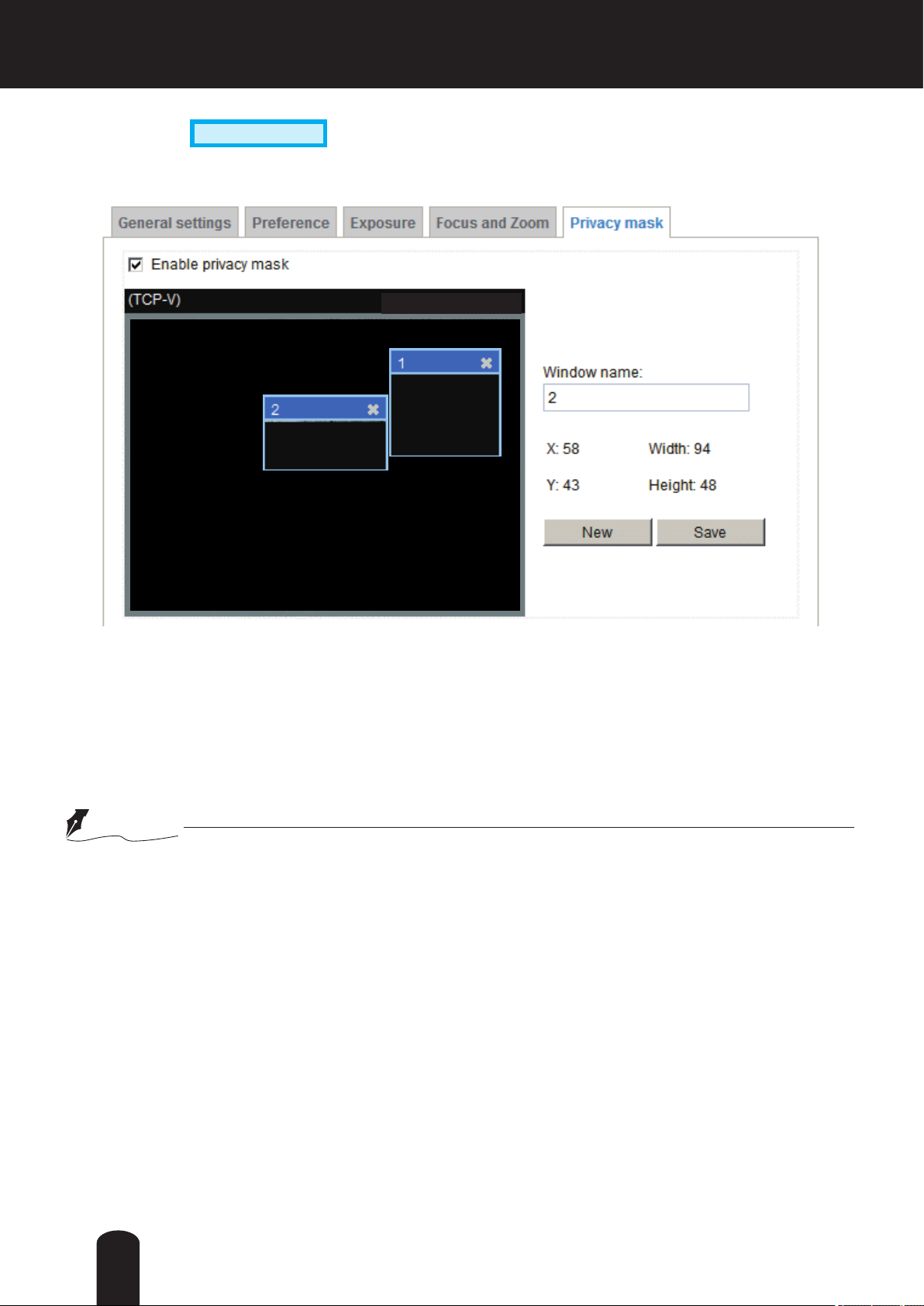
Privacy mask
Click Privacy Mask to open the settings page. On this page, you can block out certain sensitive zones to
address privacy concerns.
Advanced Mode
2011/10/15 08:59:09
■ To set the privacy mask windows, follow the steps below:
1. Click New to add a new window.
2. Use the mouse to size and drag-drop the window, which is recommended to be at least twice the size
of the object (height and width) you want to cover.
3. Enter a Window Name and click Save to enable the setting.
4. Check Enable privacy mask to enable this function.
NOTE
● Up to 5 privacy mask windows can be congured on the same screen.
● If you want to delete a congured
of the window.
mask
window, click on the ‘X’ button at the upper right corner
80

Audio and Video > Stream
FOV (Field of View)
Select a resolution from the list. The default is 3 Megapixels, and if bandwidth or frame rate per second
is of the concern you can select a lower resolution. You can congurea the FOV to 1080P (16:9) at 30fp
or 720P(16:9) at 60fps.
NOTE
● Due to the sensor's limitation, when selecting 720P(16:9) at 60fps, disable "True WDR". Otherwise ,
60fps will not be set.
81

Advanced Mode
Stream settings
This Network Camera supports multiple streams with frame size ranging from 176 x 144 to 2048 x 1536
pixels.
The denition of multiple streams:
■ Stream 1: Users can dene the "Region of Interest" (viewing region) and the "Output Frame Rate" (size
of the live view window).
■ Stream 2: Users can dene the "Region of Interest" (viewing region) and the "Output Frame Rate" (size
of the live view window).
■ Stream 3: Stream 3 does not support the "Region of Interest" conguration.
Click Viewing Window to open the viewing region settings page. On this page, you can set the Region
of Interest and the Output Frame Size for streams 1 and 2.
Please follow the steps below to set up those settings for an individual stream:
1. Select a stream to congure its viewing region.
2. Select a Region of Interest from the drop-down list. The oating frame, the same as the one in the
Gloabl View window on the home page, will resize accordingly. If you want to set up a customized
viewing region, you can also resize and re-position the oating frame to a desired position with your
mouse.
3. Choose a proper Output Frame Size from the drop-down list according to the size of monitored
device.
82
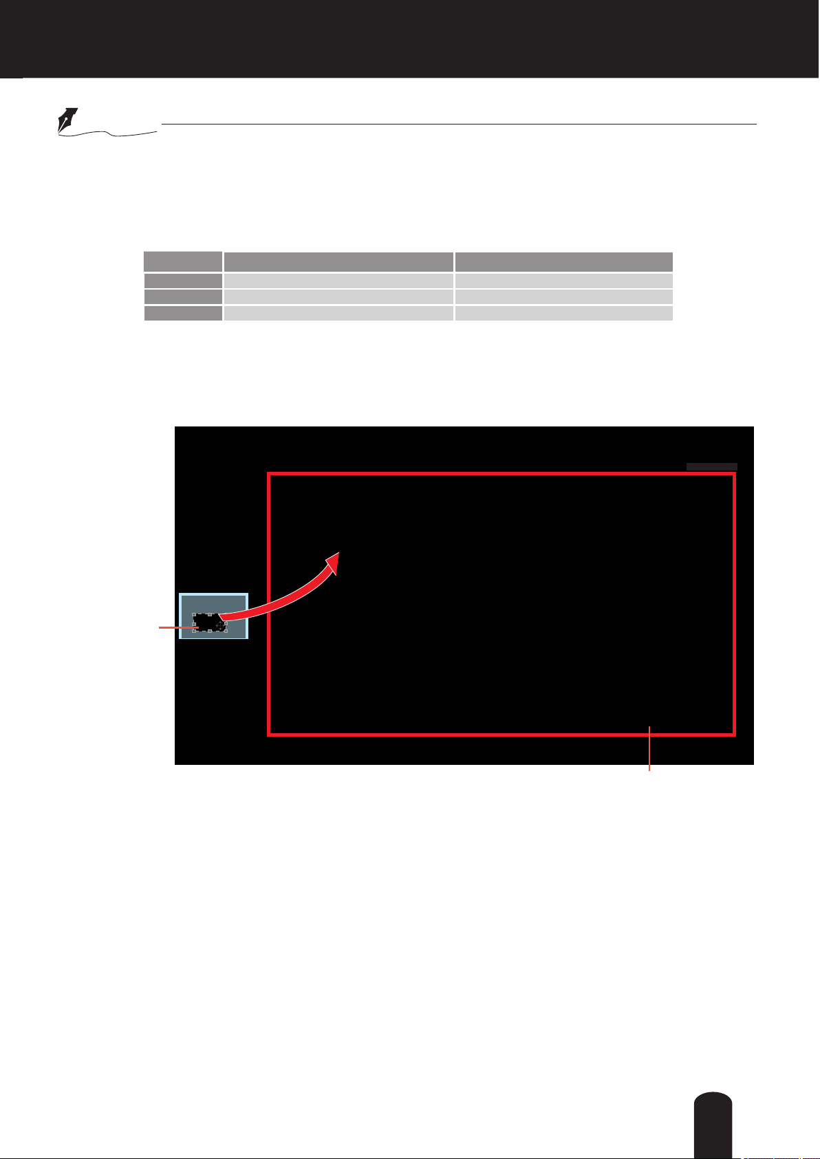
NOTE
● All the items in the “Region of Interest” cannot be greater than the “Output Frame Size“
(current maximum resolution).
■ The parameters of the multiple streams:
Stream 1 2048 X 1536 ~ 176 x 144 (Selectable) 2048 X 1536 ~ 176 x 144 (Selectable)
Stream 2 2048 X 1536 ~ 176 x 144 (Selectable) 2048 X 1536 ~ 176 x 144 (Selectable)
Stream 3 Fixed Fixed
Region of Interest Output frame size
When completed with the settings in the Viewing Window, click Save to enable the settings and click
Close to exit the window. The selected Output Frame Size will immediately be applied to the Frame
size of each video stream. Then you can go back to the home page to test the e-PTZ function. For more
information about the e-PTZ function, please refer to page 91.
2011/10/15 08:59:09
Region of Interest
(Viewing Region)
Output Frame Size
(Size of the Live View Window)
83

Click the stream item to display the detailed information. The maximum frame size will follow your
settings in the above Viewing window sections.
This Network Camera offers real-time H.264 and MJEPG compression standards (Dual Codec) for realtime viewing.
If H.264 mode is selected, the video is streamed via RTSP protocol. There are several parameters for
you to adjust the video performance:
■ Frame size
You can set up different video resolution for different viewing devices. For example, set a smaller
frame size and lower bit rate for remote viewing on mobile phones and a larger video size and a higher
bit rate for live viewing on web browsers. Note that a larger frame size takes up more bandwidth.
■ Maximum frame rate
This limits the maximum refresh frame rate per second. Set the frame rate higher for smoother video
quality. Applied frame rate changes with congured FOV automatically.
For example, if the power line frequency is set to 50Hz at 1080P Full HD, the frame rates are
selectable at 1fps, 2fps, 3fps, 5fps, 8fps, 10fps, 12fps, 15fps, 20fps and 25fps. If the power line
frequency is set to 60Hz, the frame rates are selectable at 1fps, 2fps, 3fps, 5fps, 8fps, 10fps, 12fps,
15fps, 20fps, 25fps, and 30fps. You can also select Customize and manually enter a value. The frame
rate will decrease if you select a higher resolution.
84

■ Intra frame period
Determine how often to plant an I frame. The shorter the duration, the more likely you will get better
video quality, but at the cost of higher network bandwidth consumption. Select the intra frame period
from the following durations: 1/4 second, 1/2 second, 1 second, 2 seconds, 3 seconds, and 4 seconds.
■ Video quality
• Constant bit rate:
bandwidth will be needed for data transmission.The bandwidth utilization is congurable to match
a selected level, resulting in mutable video quality performance. The bit rates are selectable at
the following rates: 20Kbps, 30Kbps, 40Kbps, 50Kbps, 64Kbps, 128Kbps, 256Kbps, 512Kbps,
768Kbps, 1Mbps, 2Mbps, 3Mbps, 4Mbps, 6Mbps, 8Mbps, 10Mbps, 12Mbps, 14Mbps, and
16Mbps.You can also select Customize and manually enter a value.
- Target bit rate:
maximum of 8Mbps.The bit rate then becomes the Average or Upper bound bit rate number.The
Network Camera will strive to deliver video streams around or within the bit rate limitation you
impose.
- Policy:
per second performance, while the image quality will be compromised.If Image quality priority is
selected, the Network Camera may drop some video frames in order to maintain image quality.
• Fixed quality
same quality; bandwidth utilization is therefore unpredictable.
• Quality: The video quality can be adjusted to the following settings: Acceptable, Satisfactory, Good,
Very Good, and Excellent. You can also select Customize and manually enter a value.
If Frame Rate Priority is selected, the Network Camera will try to maintain the frame rate
: On the other hand, if Fixed quality is selected, all frames are transmitted with the
- Maximum bit rate:
rate limitation to control the size of video streams for bandwidth and storage concerns. The
congurable bit rate starts from 1Mbps to 40Mbps.
The Maximum bit rate setting in the Fixed quality configuration can ensure a reasonable and
limited use of network bandwidth.For example, in low light conditions where a Fixed quality
setting is applied, video packet sizes can tremendously increase when noises are produced with
electrical gain.
You may also manually enter a bit rate number by selecting the Customized option.
A complex scene generally produces a larger file size, meaning that higher
select a bit rate from the pull-down menu. The bit rate ranges from 20kbps to a
With the guaranteed image quality, you might still want to place a bit
85

• Smart codec:
Smart codec can effectively reduce the video packet size while maintaining good video
quality in the selected areas of your interest. When properly congured, Smart codec can
reduce the stream size to half or even lower.
Unfold the Smart codec conguration menu by selecting the Smart codec checkbox. You
can then congure the following parameters:
• Foreground quality: Foreground is the area of your interest where you want to
maintain its video quality. The quality can be: Low, Acceptable, Satisfactory, Good, Very
Good, or Excellent.
• Background quality: Background is the area that is less important on the scene,
such as the building in the below drawing. You can congure the camera to produce
a lower-quality display for this area. The background quality can be: Low, Acceptable,
Satisfactory, Good, Very Good, or Excellent.
• Maximum bit rate: This is an upper threshold on the bit rate per second for producing
and transmitting the Smart stream video. It is congurable from 1Mbps to 40Mbps. You
can also manually enter a number (in kbps).
86
Background
Q= Acceptable or low
Foreground
Q= Good or better

• Mode:
- Auto: When set to Auto, only the moving objects and the areas around them will be
displayed with the Foreground quality. The rest of the screen will be displayed with the
Background (lower) quality.
- Manual: When selected, the Manual window setting option will be displayed. Click on it
to display the setting window. You can then manually allocate the regions of your interest
on the current eld of view. Click New, drag, and pull the window to cover the regions
of your interest. Note that the title bar on each window is not taken into account when
setting the Foreground areas.
You can create up to 3 ROI windows. Click Save to preserve your setting and click
Close to nish the conguration.
ROI_1
Foreground
Q= Very Good
Background
Q= Acceptable or low
ROI_0
Foreground
Q= Very Good
87

- Hybrid: When enabled, moving objects in the Background areas will also be displayed
using the Foreground (better) quality.
Note the following with the Smart codec setting:
1. When using the “Auto” or “Hybrid” modes, up to 30 moving objects can be displayed
using the Foreground quality.
2. The Smart codec will not be so effective in terms of bandwidth saving when applied in
a complex scene where there are objects moving constantly all over the screen.
3. Smart codec is only congurable with H.264 and streams #1 and #2.
88
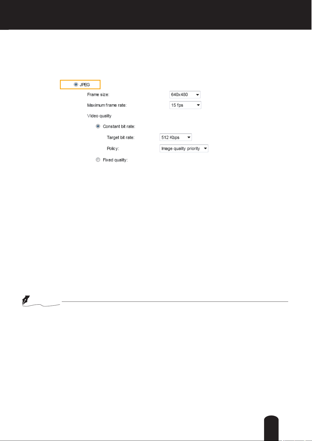
If JPEG mode is selected, the Network Camera sends consecutive JPEG images to the client, producing
a moving effect similar to a filmstrip. Every single JPEG image transmitted guarantees the same
image quality, which in turn comes at the expense of variable bandwidth usage. Because the media
contents are a combination of JPEG images, no audio data is transmitted to the client. There are three
parameters provided in MJPEG mode to control the video performance:
■ Frame size
You can set up different video resolution for different viewing devices. For example, set a smaller
frame size and lower bit rate for remote viewing on mobile phones and a larger video size and a higher
bit rate for live viewing on web browsers. Note that a larger frame size takes up more bandwidth.
■ Maximum frame rate
This limits the maximum refresh frame rate per second. Set the frame rate higher for smoother video
quality. Applied frame rate changes with congured FOV automatically.
For example, if the power line frequency is set to 50Hz at 1080P full HD, the frame rates are selectable
at 1fps, 2fps, 3fps, 5fps, 8fps, 10fps, 12fps, 15fps, 20fps, and 25fps. If the power line frequency is
set to 60Hz, the frame rates are selectable at 1fps, 2fps, 3fps, 5fps, 8fps, 10fps, 12fps, 15fps, 20fps,
25fps, and 30fps. You can also select Customize and manually enter a value. The frame rate will
decrease if you select a higher resolution.
■ Video quality
The video quality can be adjusted to the following settings: Acceptable, Satisfactory, Good, Very Good,
and Excellent. You can also select Customize and manually enter a value.
NOTE
►
Video quality and xed quality refers to the compression rate, so a lower value will produce higher
quality.
►
Converting high-quality video may signicantly increase the CPU loading, and you may encounter
streaming disconnection or video loss while capturing a complicated scene. In the event of
occurance, we suggest you customize a lower video resolution or reduce the frame rate to obtain
smooth video.
89
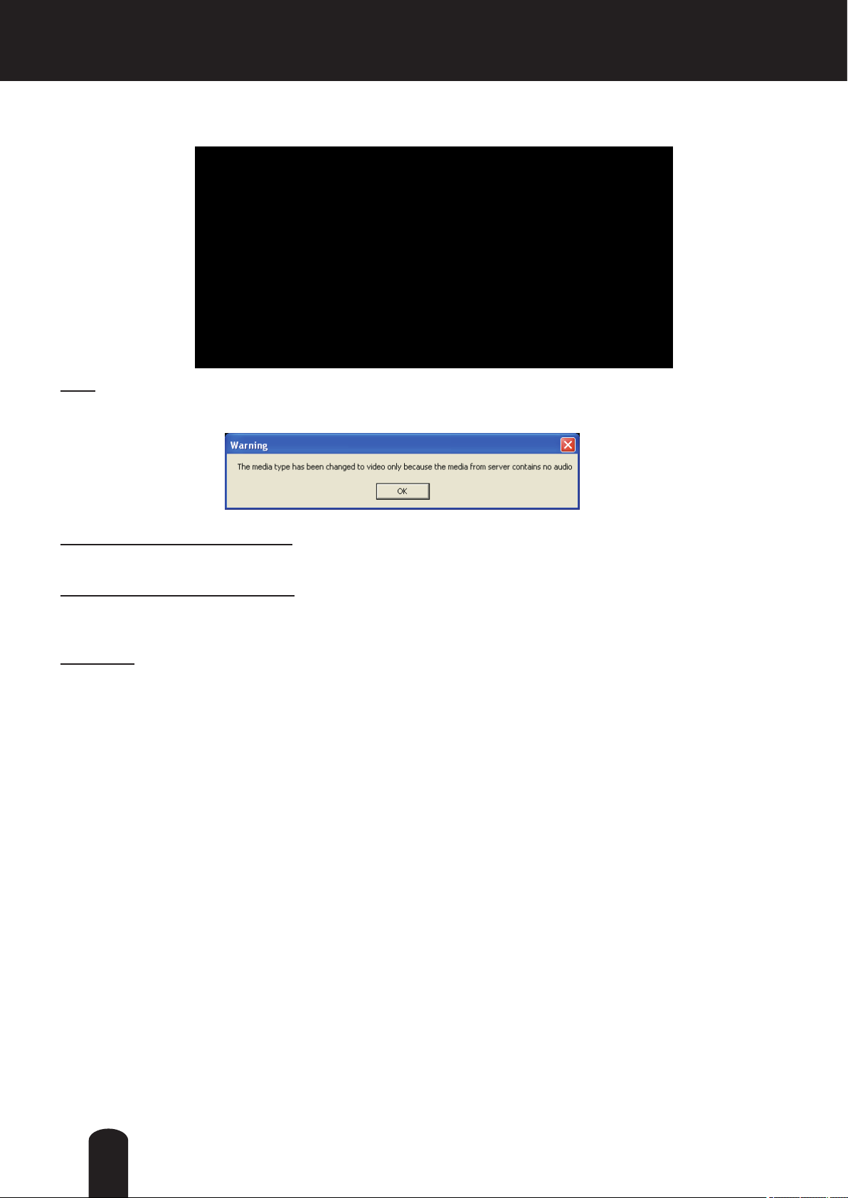
Audio and Video > Audio
Audio Settings
Mute: Select this option to disable audio transmission from the Network Camera to all clients. Note that
if muted, no audio data will be transmitted even if audio transmission is enabled on the Client Settings
page. In that case, the following message is displayed:
Internal microphone input gain: Select the gain of the internal audio input according to ambient
conditions. Adjust the gain from 100% (most sensitive) to 0% (least sensitive).
External microphone input gain: Select the gain of the external audio input according to ambient
conditions. Adjust the gain from 100% (most sensitive) to 0% (least sensitive).
Audio type: Select audio codec AAC or GSM-AMR and the bit rate.
■ AAC provides good sound quality at the cost of higher bandwidth consumption. The bit rates are
selectable from: 16Kbps, 32Kbps, 48Kbps, 64Kbps, 96Kbps, and 128Kbps.
■ G.711 also provides good sound quality and requires about 64Kbps. Select pcmu (μ-Law) or pcma
(A-Law) mode.
■ G.726 is a speech codec standard covering voice transmission at rates of 16, 24, 32, and 40kbit/s.
When completed with the settings on this page, click Save to enable the settings.
90

PTZ > PTZ settings
Advanced Mode
This section explains how to control the Network Camera’s Pan/Tilt/Zoom operation.
Digital: Control the e-PTZ operation. It allows users to quickly move the focus to a precongured target area for close-up viewing without physically zooming the camera.
Digital PTZ Operation (E-PTZ Operation)
Activated mode is “Digital“, the e-PTZ control settings section will be displayed as shown below:
2011/10/15 17:08:56
Select stream: Select one of the stream 1 or 2 to set up the e-PTZ control. Please note that each stream
can be set up with its own preset and patrol settings. Refer to the following page for details about how to
set up preset and patrol settings.
Auto pan/patrol speed: Select the speed from 1~5 (slow/fast) to set up the Auto pan/patrol speed control.
When completed with the settings of e-PTZ, click Save to enable the settings on this page.
91

Home page in E-PTZ Mode
2011/10/15 08:59:09
■ The e-Preset Positions will also be displayed on the home page. Select one from the drop-down list,
and the Network Camera will move to the selected e-preset position.
■ If you have set up different e-preset positions for streams 1 or 2, you can select one of the video
streams to display its separate e-preset positions.
Global View
In addition to using the e-PTZ control panel, you can also use the mouse to drag or resize the oating
frame to pan/tilt/zoom the viewing region. The live view window will also move to the viewing region
accordingly.
Moving Instantly
If you check this item, the live view window will switch to the new viewing region instantly after you move
the oating frame.
Click on Image
The e-PTZ function also supports “Click on Image“. When you click on any point of the Global View
Window or Live View Window, the viewing region will also move to that point.
92

Patrol settings
You can select some preset positions for the Network Camera to patrol.
Please follow the steps below to set up a patrol schedule:
1. Select the preset locations on the list, and click
.
2. The selected preset locations will be displayed on the Patrol locations list.
3. Set the Dwell time for the streaming view to stay at the preset location during auto patrol.
4. If you want to delete a preset location from the Patrol locations list, select it and click Remove.
5. Select a location and click
to rearrange the patrol order.
6. Select patrol locations you want to save in the list and click Save to enable the patrol settings.
7. To perform a pre-congured patrol, return to homepage and click on the Patrol button.
2011/10/15 17:08:56
2
1
3
54
6
93
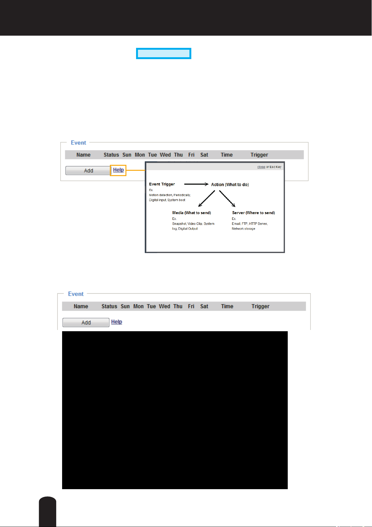
Event > Event settings
Advanced Mode
This section explains how to congure the Network Camera to respond to particular situations
(event). A typical application is that when a motion is detected, the Network Camera sends
buffered images to an FTP server or e-mail address as notifications. Click on Help, there is
an illustration shown in the pop-up window explaining that an event can be triggered by many
sources, such as motion detection or external digital input devices. When an event is triggered,
you can specify what type of action that will be performed. You can configure the Network
Camera to send snapshots or videos to your email address or FTP site.
Event
To set an event with recorded video or snapshots, it is necessary to configure the server and media
settings so that the Network Camera will know what action to take (such as which server to send the
media les to) when a trigger is activated. An event is an action initiated by a user-dened trigger source.
In the Event column, click Add to open the event settings window.
94

■ Event name: Enter a name for the event setting.
■ Enable this event: Select this option to enable the event setting.
■ Priority: Select the relative importance of this event (High, Normal, or Low). Events with a higher
priority setting will be executed rst.
■ Detect next event after
seconds: Enter the duration in seconds to pause motion detection after a
motion is detected. This can prevent event-related actions to be too frequently performed.
Follow the steps 1~3 to arrange the three elements -- Schedule, Trigger, and Action to set an event. A
total of 3 event settings can be congured.
1. Schedule
Specify the period for the event. Please select the days of the week and the time in a day (in 24-hr time
format) to specify when will the event-triggering conditions take effect.
2. Trigger
This is the cause or stimulus which denes what will trigger the event. The trigger source can be congured to use the Network Camera’s built-in motion detection mechanism or external digital inputs.
There are several choices of trigger sources as shown on next page.
Select each item to display its
related options.
■ Video motion detection
This option makes use of the built-in motion detection mechanism as a trigger source. To enable this
function, you need to congure a Motion Detection Window rst. For more information, please refer to
Motion Detection on page 108 for details.
■ Periodically
This option allows the Network Camera to trigger periodically for every other dened minute. Up to 999
minutes are allowed.
■ Digital input
This option allows the Network Camera to use an external digital input device or sensor as a trigger
source. Depending on your application, there are many choices with digital input devices on the market
which help detect changes in temperature, vibration, sound, light, etc.
■ System boot
This option triggers the Network Camera when the power to the Network Camera is disconnected.
■ Recording notify
This option allows the Network Camera to trigger when the recording disk is full or when recording
starts to overwrite older data.
95

■ Audio detection
A preset threshold can be congured with an external microphone as the trigger to system event. The
triggering condition can be an input exceeding or falling below a threshold. Audio detection can take
place as a complement to motion detection or as a method to detect activities not covered by the
camera's view.
Once you have a preset audio alarm level, you can dene the triggering condition either as an audio
input rises above or falls below the alarm level.
■ Camera tampering detection
This option allows the Network Camera to trigger when the camera detects that is is being tampered
with. To enable this function, you need to congure the Tampering Detection option rst. Please refer
to page 111 for detailed information.
■ Manual Trigger
This option allows users to enable event triggers manually by clicking the on/off button on the
homepage. Please congure 1 to 3 associated events before using this function.
96

■ Extension platform (EP)
It is presumed that you already uploaded and enabled the EP modules before you can
associatee EP triggers with an Event setting.
Click on the Set EP Trigger button to open the EP setup menu. The triggering conditions
available with 3rd-party software modules known as EP will be listed. Use the arrow buttons to
select these triggers. Users may implant these modules for different purposes such as triggering
motion detection, or applications related to video analysis, etc. Please refer to page 114 for the
conguration options with EP modules.
Once the triggers are congured, they will be listed under the EP option.
97
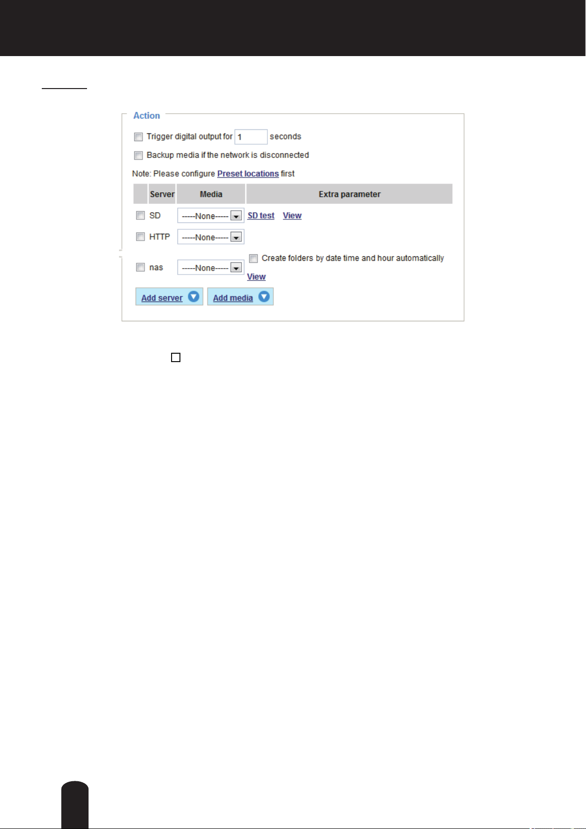
3. Action
Dene the actions to be performed by the Network Camera when a trigger is activated.
■ Trigger digital output for
Select this option to turn on the external digital output device when a trigger is activated. Specify the
length of the trigger interval in the text box.
■ Backup media if the network is disconnected
Select this option to backup media le on SD card if the network is disconnected. This function will only
be displayed after you set up a networked storage device (NAS).
seconds
98

Add server
To congure an event with video recording or snapshots, it is necessary to congure/provide servers and
storage media settings so that the Network Camera will know where to send the media les to when a
trigger is activated.
Click Add server to unfold the server setting window. You can specify where the notication messages
are sent when a trigger is activated. A total of 5 server settings can be congured.
There are four choices of server types available: Email, FTP, HTTP, and Network storage.
to display the detailed conguration options. You can congure either one or all of them.
Select the item
Server type - Email
Select to send the media les via email when a trigger is activated.
■ Server name: Enter a name for the server setting.
■ Sender email address: Enter a valid email address as the sender address.
■ Recipient email address: Enter a valid email address as the recipient address.
■ Server address: Enter the domain name or IP address of the email server.
■ User name: Enter the user name of the email account if necessary.
■ Password: Enter the password of the email account if necessary.
■ Server port: The default mail server port is set to 25. You can also manually set another port.
If your SMTP server requires a secure connection (SSL), check This server requires a secure
connection (SSL).
99
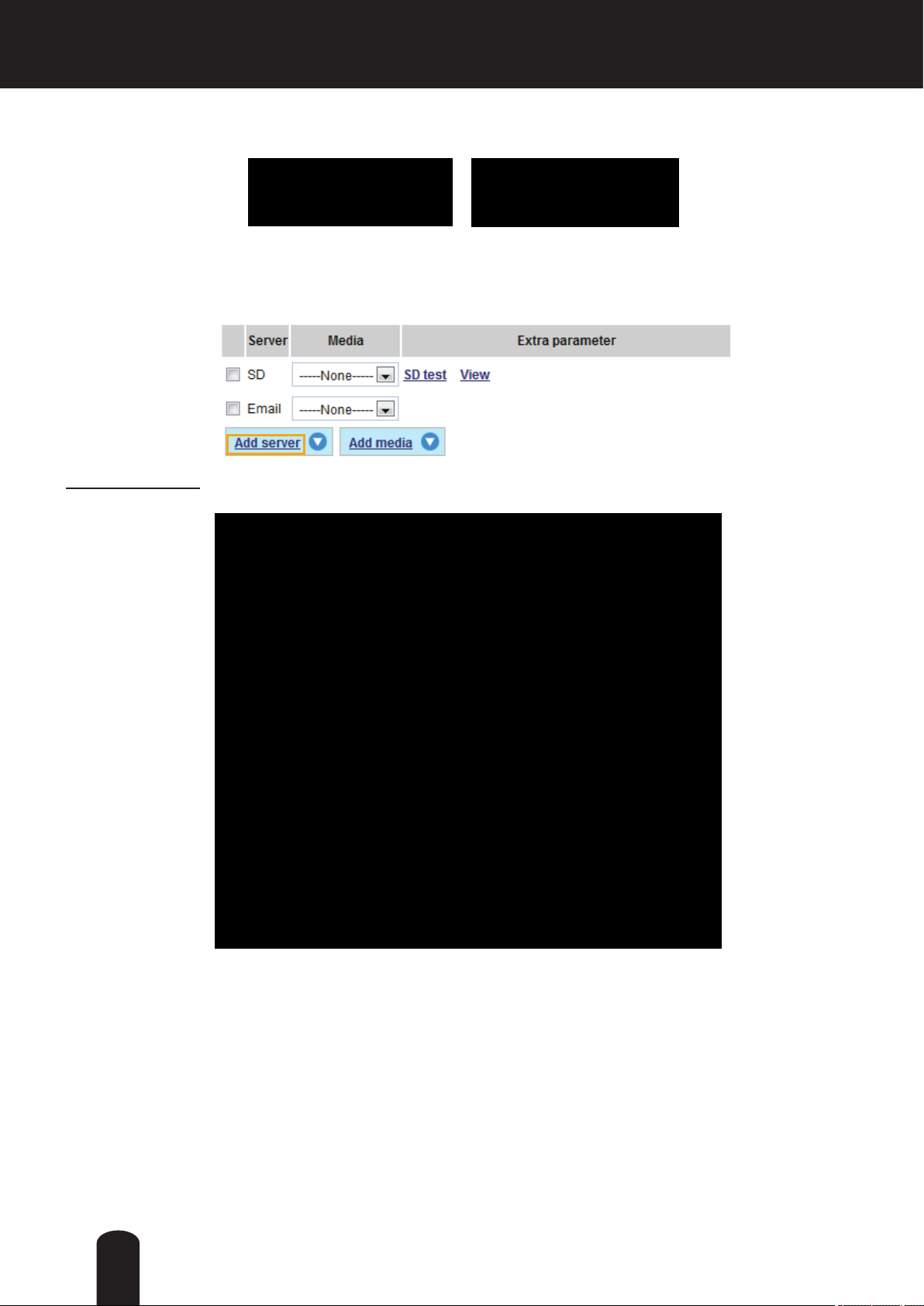
To verify if the email settings are correctly congured, click Test. The result will be shown in a pop-up
window. If successful, you will also receive an email indicating the result.
Click Save server to enable the settings, then click Close to exit the Add server page.
After you set up the rst event server, a new item for event server will automatically appear on the Server
list. If you wish to add more server options, click Add server.
Server type - FTP
Select to send the media les to an FTP server when a trigger is activated.
■ Server name: Enter a name for the server setting.
■ Server address: Enter the domain name or IP address of the FTP server.
■ Server port: By default, the FTP server port is set to 21. It can also be assigned to another port number
between 1025 and 65535.
■ User name: Enter the login name of the FTP account.
■ Password: Enter the password of the FTP account.
■ FTP folder name
Enter the folder where the media le will be placed. If the folder name does not exist, the Network
Camera will create one on the FTP server.
100
 Loading...