

Page 1
DIGITAL VIDEO
DVD VIDEO RECORDER
D-R2SU
Introduction
D-R2SC
D-KR2SU
OWNER’S MANUAL
INSTALLATION
GUIDE
Read this booklet first.
Connections
Basic Setup
S
PM0015866010
© 2004 Toshiba Corporation
Page 2
Introduction
SAFETY PRECAUTIONS
WARNING
RISK OF ELECTRIC SHOCK
DO NOT OPEN
AVIS
WARNING : TO REDUCE THE RISK OF
ELECTRIC SHOCK, DO NOT REMOVE
COVER (OR BACK). NO USERSERVICEABLE
PARTS INSIDE. REFER SERVICING TO
QUALIFIED SERVICE PERSONNEL.
WARNING: TO REDUCE THE RISK OF FIRE OR ELECTRIC SHOCK, DO NOT EXPOSE THIS APPLIANCE
CAUTION: TO PREVENT ELECTRIC SHOCK, MATCH WIDE BLADE OF PLUG TO WIDE SLOT, FULLY
ATTENTION: POUR EVITER LES CHOCS ELECTRIQUES, INTRODUIRE LA LAME LA PLUS LARGE DE LA
RISQUE DE CHOC ELECTRIQUE NE
PAS OUVRIR
TO RAIN OR MOISTURE. DANGEROUS HIGH VOLTAGES ARE PRESENT INSIDE THE
ENCLOSURE. DO NOT OPEN THE CABINET. REFER SERVICING TO QUALIFIED PERSONNEL
ONLY.
INSERT.
FICHE DANS LA BORNE CORRESPONDANTE DE LA PRISE ET POUSSER JUSQU’AU FOND.
The lightning flash with arrowhead symbol, within an equilateral triangle, is intended to alert the user to the presence of
uninsulated “dangerous voltage” within the product’s enclosure that may be of sufficient magnitude to constitute a risk
of electric shock to persons.
The exclamation point within an equilateral triangle is intended to alert the user to the presence of important operating and maintenance (servicing) instructions in the literature
accompanying the appliance.
The symbol for CLASS II (Double Insulation)
CAUTION: This DVD video recorder employs a Laser System.
To ensure proper use of this product, please read this owner’s manual carefully and retain for
future reference. Should the unit require maintenance, contact an authorized service location see service procedure.
Use of controls or adjustments or performance of procedures other than those specified herein
may result in hazardous radiation exposure.
To prevent direct exposure to laser beam, do not try to open the enclosure.
Visible and invisible laser radiation when open and interlocks defeated.
DO NOT STARE INTO BEAM.
FCC NOTICE: This equipment has been tested and found to comply with the limits for a Class B digital device,
pursuant to part 15 of the FCC Rule. These limits are designed to provide reasonable protection
against harmful interference in a residential installation.
This equipment generates, uses, and can radiate radio frequency energy and, if not installed
and used in accordance with the instructions, may cause harmful interference to radio
communications.
However, there is no guarantee that interference will not occur in a particular installation.
If this equipment does cause harmful interference to radio or television reception, which can be
determined by turning the equipment off and on, the user is encouraged to try to correct the
interference by one or more of the following measures:
- Reorient or relocate the receiving antenna.
- Increase the separation between the equipment and receiver.
- Connect the equipment into an outlet on a circuit different from that to which the receiver is
connected.
- Consult the dealer or an experienced radio/TV technician for help.
WARNING: Changes or modifications made to this equipment, not expressly approved by Toshiba, or
parties authorized by Toshiba, could void the user’s authority to operate the equipment.
2
Page 3
Note to cable system installer:
This reminder is provided to call the cable system installer’s attention to Article 820-40 of the NEC that
provides guidelines for proper grounding and, in particular, specifies that the cable ground shall be connected
to the grounding system of the building, as close to the point of cable entry as practical.
Copyright:
It is permissible to record television programs, film, video tapes and other material only in the event
that third party copyrights and other rights are not violated.
The instructions shall state that an ALL-POLE MAINS SWITCH with a contact separation of at least 3 mm in
each pole shall be incorporated in the electrical installation of the building.
CAUTION: These servicing instructions are for use by qualified service personnel only. To reduce the
risk of electric shock do not perform any servicing other than that contained in the operating
instructions unless you are qualified to do so.
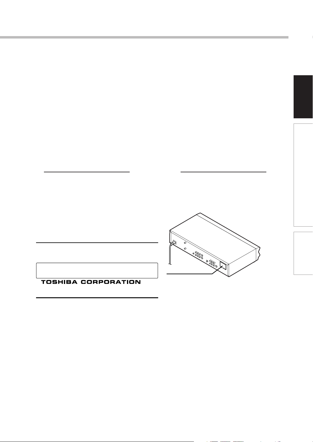
In the spaces provided below, record the Model and Serial No. located on the rear panel of your recorder.
Model No. Serial No.
Retain this information for future reference.
Location of the required label
PRODUCT IS CERTIFIED BY THE MANUFACTURER TO
COMPLY WITH DHHS RULE 21 CFR SUBCHAPTER J
APPLICABLE AT THE DATE OF MANUFACTURE.
MANUFACTURED
Introduction
Connections
Basic Setup
1-1,SHIBAURA 1-CHOME,MINATO-KU.
TOKYO 105-8001,JAPAN
3
Page 4

IMPORTANT SAFETY INSTRUCTIONS
CAUTION: PLEASE READ AND OBSERVE ALL WARNINGS AND INSTRUCTIONS GIVEN IN THIS
OWNER’S MANUAL AND THOSE MARKED ON THE UNIT. RETAIN THIS BOOKLET FOR
FUTURE REFERENCE.
This set has been designed and manufactured to assure personal safety. Improper use can result in electric
shock or fire hazard. The safeguards incorporated in this unit will protect you if you observe the following
procedures for installation, use and servicing. This unit is fully transistorized and does not contain any parts that
can be repaired by the user.
DO NOT REMOVE THE CABINET COVER, OR YOU MAY BE EXPOSED TO DANGEROUS VOLTAGE. REFER
SERVICING TO QUALIFIED SERVICE PERSONNEL ONLY.
1. Read these instructions.
2. Keep these instructions.
3. Heed all warnings.
4. Follow all instructions.
5. Do not use this apparatus near water.
6. Clean only with dry cloth.
9. Do not defeat the safety purpose of the
polarized or grounding-type plug. A polarized
plug has two blades with one wider than the
other. A grounding type plug has two blades
and a third grounding prong. The wide blade or
the third prong are provided for your safety. If
the provided plug does not fit into your outlet,
consult an electrician for replacement of the
obsolete outlet.
10.Protect the power cord from being walked on or
pinched particularly at plugs, convenience
receptacles, and the point where they exit from
the apparatus.
11. Only use attachments/accessories specified by
the manufacturer.
7. Do not block any ventilation openings. Install in
accordance with the manufacturer’s
instructions.
8. Do not install near any heat sources such as
radiators, heat registers, stoves, or other
apparatus (including amplifiers) that produce
heat.
4
12.Use only with the cart, stand, tripod, bracket, or
table specified by the manufacturer, or sold with
the apparatus. When a cart is used, use caution
when moving the cart/apparatus combination to
avoid injury from tip-over.
S3125A
Page 5

Introduction
13.Unplug this apparatus during lightning storms or
when unused for long periods of time.
14.Refer all servicing to qualified service
personnel. Servicing is required when the
apparatus has been damaged in any way, such
as power-supply cord or plug is damaged, liquid
has been spilled or objects have fallen into the
apparatus, the apparatus has been exposed to
rain or moisture, does not operate normally, or
has been dropped.
ADDITIONAL SAFETY INSTRUCTIONS
15.When you use headphones, keep the volume at
a moderate level. If you use the headphones
continuously with high volume sound, it may
cause hearing damage.
19.Do not place a heavy object on or step on the
apparatus. The object may fall, causing serious
personal injury and serious damage to the
apparatus.
20.Do not place the apparatus on amplifiers or
equipment that may produce heat.
21.Do not cover the ventilating holes for the inside
cooling fan.
22.Do not use a cracked, deformed, or repaired
disc. These discs are easily broken and may
cause serious personal injury and apparatus
malfunction.
Introduction
Connections
16.Do not overload wall outlets; extension cords,
or integral convenience receptacles as this can
result in a risk of fire or electric shock.
17.Apparatus should not be exposed to dripping or
splashing and no objects filled with liquids, such
as vases, should be placed on the apparatus.
18.Keep your fingers well clear of the disc tray as
it is closing. Neglecting to do so may cause
serious personal injury.
Basic Setup
23.If the apparatus should smoke or smell,
immediately disconnect the power cord from the
wall outlet. Wait until the smoke or smell stops,
then ask your dealer for a check and repair.
Neglecting to do so may cause fire.
24.While it is thundering, do not touch the connecting
cables or the apparatus.
25.The apparatus includes lead, an ingredient of
solder used on the PCB, which is a harmful
substance to human and the environment. When
disposing of this apparatus, follow the rules and
regulations in your area.
5
Page 6

Introduction
Precautions
Notes on handling
Never disconnect the power cord from a wall outlet
while the recorder is not in standby mode, unless it is
in an emergency. Doing so may cause malfunction.
When shipping the recorder, the original shipping
carton and packing materials come in handy. For
maximum protection, repack the unit as it was
originally packed at the factory.
Do not use volatile liquids, such as insect spray, near
the recorder. Do not leave rubber or plastic products in
contact with the recorder for a long time. They will
leave marks on the finish.
The top and rear panels of the recorder may become
warm after a long period of use. This is not a
malfunction.
When not in use
For usual absence
Be sure to remove the disc from the recorder and turn
off the power.
Prolonged absence
Unplug the recorder from a wall outlet.
Notes on locating
Place the recorder on a level surface. Do not use it on
a shaky or unstable surface such as a wobbly table or
inclined stand. The loaded disc may dislodge from its
proper position and cause damage to the recorder.
Before placing the recorder, make sure that the
surface can stand the weight of the recorder. For
safety, avoid placing the recorder in a high location, as
an accidental fall of the recorder may cause personal
injury.
When you place this recorder near a TV, radio, or
VCR, the playback picture may become poor and the
sound may be distorted depending on the condition
and location of said equipment. In such an event,
place the recorder as far away much as possible from
the TV, radio, or VCR.
Do not install this product in an area where it will be
exposed to large amounts of oily smoke, steam or
dust, as such exposure could result in fire or electric
shock. Cigarette smoke, dust etc. can cause the
product to malfunction.
Notes on cleaning
Use a soft, dry cloth for cleaning.
For stubborn dirt, use a damp cloth (containing a mild
detergent) to wipe the unit. Ensure the unit is
unplugged before you do this. Use a dry cloth to wipe
it dry.
Do not use any type of solvent, such as thinner or
benzine, as they may damage the surface of the
recorder.
If you use a chemical saturated cloth to clean the unit,
follow that product’s instructions.
To obtain a clear picture
The recorder is a high technology, precision device. If the
optical pick-up lens and disc drive parts are dirty or worn
down, the picture quality deteriorates. To obtain a clear
picture, we recommend regular inspection and
maintenance (cleaning or parts replacement) every 1,000
hours of use depending on the operating environment.
For details, contact your nearest dealer.
Notes on antennas
Image and sound quality depend very much on signal
reception.
Reception may be poor in weak signal areas. In this
event, consult your dealer, or purchase a commercially
available antenna booster. Refer to the booster’s
instruction manual for installation details.
6
Page 7

Notes on recording and editing
Power Outage
When you record/edit important content, make trial
operations beforehand to confirm the recorder can
function properly.
Toshiba does not compensate for content which was
not recorded/edited because of some malfunction of
this product or discs during operation, and is not liable
for incidental damages (such as profit loss or
interruption of business, etc.) produced in such
conditions.
When the power cord is disconnected or when a
power failure occurs during any operation of this
product, all contents recorded in this recorder may be
erased.
Depending on the channel or program, an excessive
sound input level may cause noise or cut of recorded
sound. Adjust the initial setting of the recording level
when necessary.
If a program you have set a timer recording includes
copy restriction signals, it may not be recorded. When
programming a recording, confirm that a program you
want to record is not copy-restricted.
Exemptions
Toshiba is not liable for any damage caused by fires,
natural disaster (such as thunder, earthquake, etc.),
acts by third parties, accidents, owner’s intentional or
unintentional misuse, or uses in other improper
conditions.
Toshiba is not liable for incidental damages (such as
profit loss or interruption in business, modification or
erasure of recorded data, etc.) caused by use or
inability to use of this product.
Toshiba is not liable for any damage caused by
neglect of the instructions described in the owner’s
manual.
Toshiba is not liable for any damage caused by
misuse or malfunction through simultaneous use of
this product and the connected equipment or software
that Toshiba is not concerned with.
Toshiba does not compensate for contents which were
not recorded/edited because of some malfunctions of
this product or discs during operation, and is not liable
for incidental damages (such as profit loss or
interruption in business, etc.) produced by such
conditions.
After a power outage the clock display will flash. Set
the clock to the correct time.
Notes on the unit
Do not give a shock or shake (especially during
operation).
Do not use in a shaky or unstable location.
Hold the unit horizontally.
Do not cover the ventilation holes for the cooling fan of
the unit.
Do not use in a place where the temperature rises or
changes rapidly.
Do not disconnect the power plug from a wall outlet
while the unit is turned on.
Do not disconnect the power plug from the wall outlet
or break the power supply to the unit during recording
or playing. Before disconnecting the power plug, be
sure to press the power button and make sure the unit
ends the finishing process and power turns off
completely. If the power plug is disconnected or power
supply is disrupted while the unit is recording, all
recorded content will be erased.
Toshiba is not liable for any damage or loss of
recorded data caused by shock, shakes, misoperation
or malfunction.
Introduction
Connections
Basic Setup
7
Page 8
Introduction
Precautions (Continued)
Notes on moisture condensation
Moisture condensation damages the unit. Please
read the following carefully.
Moisture condensation occurs, for example, when you
pour a cold drink into a glass on a warm day. Drops of
water form on the outside of the glass. In the same way,
moisture may condense on the optical pick-up lens inside
this unit, one of the most crucial internal parts of the unit.
f
o
m
e
o
l
p
i
s
m
a
x
E
n
o
c
Moisture condensation occurs during the
following cases.
When you bring the unit directly from a cold place to a
warm place.
When you use the unit in a room where you just
turned on the heater, or a place where the cold wind
from the air conditioner directly hits the unit.
In summer, when you use the unit in a hot and humid
place just after you move the unit from an air
conditioned room.
When you use the unit in a humid place.
t
u
r
e
s
n
a
e
t
i
d
o
n
!
Optical pick-up
lens
It’s too
warm!
Notes on copyright
It is prohibited by law to copy, broadcast, show,
broadcast on cable, play in public, and rent
copyrighted material without permission.
Some DVD video discs are copy protected, and any
recordings made from these discs will be distorted.
This unit incorporates copyright protection technology
that is protected by method claims of certain U.S.
patents and other intellectual property rights owned by
Macrovision Corporation and other rights owners. Use
of this copyright protection technology must be
authorized by Macrovision Corporation, and is
intended for home and other limited viewing uses only
unless otherwise authorized by Macrovision
Corporation. Reverse engineering or disassembly is
prohibited.
This unit incorporates CPRM (Content Protection for
Recording Media) technology for copyright protection
in recording devices, authorized by DVD forum.
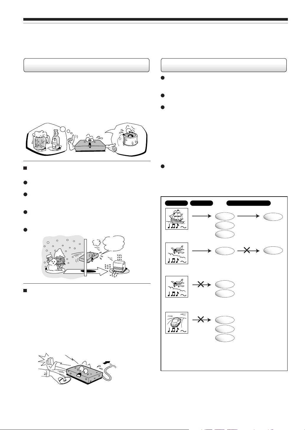
Recording and copying on this recorder depend on the
contents as described below.
Program Recording
Can be
recorded
Copy free
Can be
recorded
Recording once
permitted
Copy within the same disc
DVD-RAM
DVD-RW
DVD-R
DVD-RAM
Can be
copied
Cannot be
copied
DVD-RAM
DVD-RAM
Do not use the unit when moisture condensation
may occur.
If you use the unit in such a situation, it may damage
discs and internal parts. Remove the disc, connect the
power cord of the unit to the wall outlet, turn on the
unit, and leave it for two or three hours. After two or
three hours, the unit will have warmed up and
evaporated any moisture. Keep the unit connected to
the wall outlet and moisture condensation will seldom
occur.
Wait!
Wall outlet
8
DVD-RW
DVD-R
DVD-RAM
DVD-RW
DVD-R
Recording once
permitted
Recording
prohibited
Cannot be
recorded
Cannot be
recorded
• Regardless of program content, copies cannot be
made within the same DVD-RW disc or DVD-R disc.
Page 9

VCR Plus+, C3 and PlusCode are registered trademarks
of Gemstar Development Corporation. The VCR Plus+
system is manufactured under license from Gemstar
Development Corporation.
Manufactured under license from QSound Labs, Inc.
U.S. patent Nos. 5,105,462, 5,208,860 and 5,440,638
and various foreign counterpart. Copyright QSound Labs,
Inc. 1998-2002. QXpander
Labs, Inc. All rights reserved.
TM
is a trademark of QSound
Introduction
Connections
Basic Setup
9
Page 10
Introduction
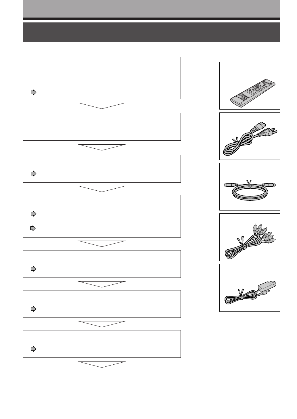
Accessories
Remote control
Batteries (AAA) x 2
Power Cord
Coaxial cable
Video/Audio cable
IR control cable
• Owner's manual
(INSTALLATION GUIDE)
• Owner's manual
(OPERATIONS)
• Registration card
Installation procedure
Read carefully “SAFETY PRECAUTIONS”,
“IMPORTANT SAFETY INSTRUCTIONS” and
“Precautions”.
(
pages 2 to 9)
Check the supplied accessories.
(See right)
Load the batteries in the remote control.
(
page 12)
Connect an antenna to the recorder.
(
page 14)
Connect a cable box or satellite system to the recorder.
(
pages 16 to 19)
Connect the recorder to a TV.
(
pages 14 to 15, 20)
Connect optional equipment to the recorder.
(
pages 21 to 24)
Make the initial settings.
(
page 26)
Your recorder is ready. Read the separate
volume “OPERATIONS”.
10
Page 11

Introduction
Table of Contents
Introduction
SAFETY PRECAUTIONS ...................................................................................................... 2
IMPORTANT SAFETY INSTRUCTIONS ............................................................................... 4
Precautions........................................................................................................................... 6
Installation procedure........................................................................................................ 10
Preparation of the remote control .................................................................................... 12
Connections
Connecting an antenna and TV......................................................................................... 14
Connecting to cable TV signal .......................................................................................... 16
Connecting to a satellite system ...................................................................................... 18
Connecting to the IR control cable................................................................................... 19
Connecting to a TV equipped with component video inputs ......................................... 20
Connecting to an audio system ........................................................................................ 21
Basic Setup
Introduction
Connections
Connecting to an amplifier equipped with a Dolby Digital decoder ....................... 22
Connecting to an amplifier equipped with Dolby Surround Pro Logic ................... 22
Connecting to an amplifier equipped with a DTS decoder .................................... 23
Connecting to an amplifier equipped with an MPEG2 audio decoder ................... 23
Connecting to an amplifier equipped with a digital audio input ............................. 24
Basic Setup
Starting up the recorder .................................................................................................... 26
A: Initial Settings ................................................................................................................ 28
1: Language setting ............................................................................................... 30
2: Time and date setting ........................................................................................ 31
3: Channel setting ................................................................................................. 34
4: Set top box setting............................................................................................. 36
5: Guide channel setting........................................................................................ 40
B: Output sound setting .................................................................................................... 42
C: TV shape setting ............................................................................................................ 44
D: Remote control settings ............................................................................................... 46
Operating a TV with the remote control of this recorder........................................ 46
Operating the second and third TOSHIBA DVD video recorders with the
remote control of this recorder .............................................................................. 48
Limited Warranty DVD PLAYER/RECORDER ................................................................... 50
CANADIAN WARRANTY INFORMATION .......................................................................... 52
11
Page 12
Introduction
Preparation of the remote control
Notes on batteries
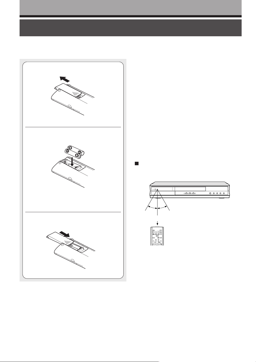
Open the cover.
1
Insert batteries (AAA size).
2
Improper use of batteries may cause battery leakage and
corrosion. To operate the remote control correctly, follow the
instructions below.
• Do not insert batteries into the remote control in the wrong
direction.
• Do not charge, heat, open, or short-circuit the batteries. Do
not throw batteries into a fire.
• Do not leave dead or exhausted batteries in the remote
control.
• Do not use different types of batteries together, or mix old
and new batteries.
• If you do not use the remote control for a long period of
time, remove the batteries to avoid possible damage from
battery corrosion.
• If the remote control does not function correctly or if the
operating range is reduced, replace all batteries with new
ones.
• If battery leakage occurs, wipe the battery liquid from the
battery compartment, then insert new batteries.
Make sure to match the + and – on the
batteries to the marks inside the battery
compartment.
Close the cover.
3
Operating with the remote control
Point the remote control at the remote sensor and
press the buttons.
30°
30°
Within about 7 m (23 ft)
OPEN/CLOSE
DVD
MENU
RETURN
TOP MENU
SUBTITLE
ANGLE
AUDIO
CHANNEL
TIMESLIP
V-REMOTE
INSTANT SKIPINSTANT REPLAY
REC MENU EDIT MENU
LIBRARY
CONTENT MENU
S
K
W
I
O
P
L
S
Distance : About 7 m (23 ft) from the front of the
remote sensor
Angle : About 30° in each direction of the front of
the remote sensor
* Do not expose the remote sensor of the recorder to a
strong light source such as direct sunlight or other
illumination. If you do so, you may not be able to
operate the recorder via the remote control.
12
Notes
• Direct the remote control at the remote sensor of the
recorder.
• Do not drop or give the remote control a shock.
• Do not leave the remote control near an extremely hot or
humid place.
• Do not spill water or put anything wet on the remote control.
• Do not disassemble the remote control.
Page 13
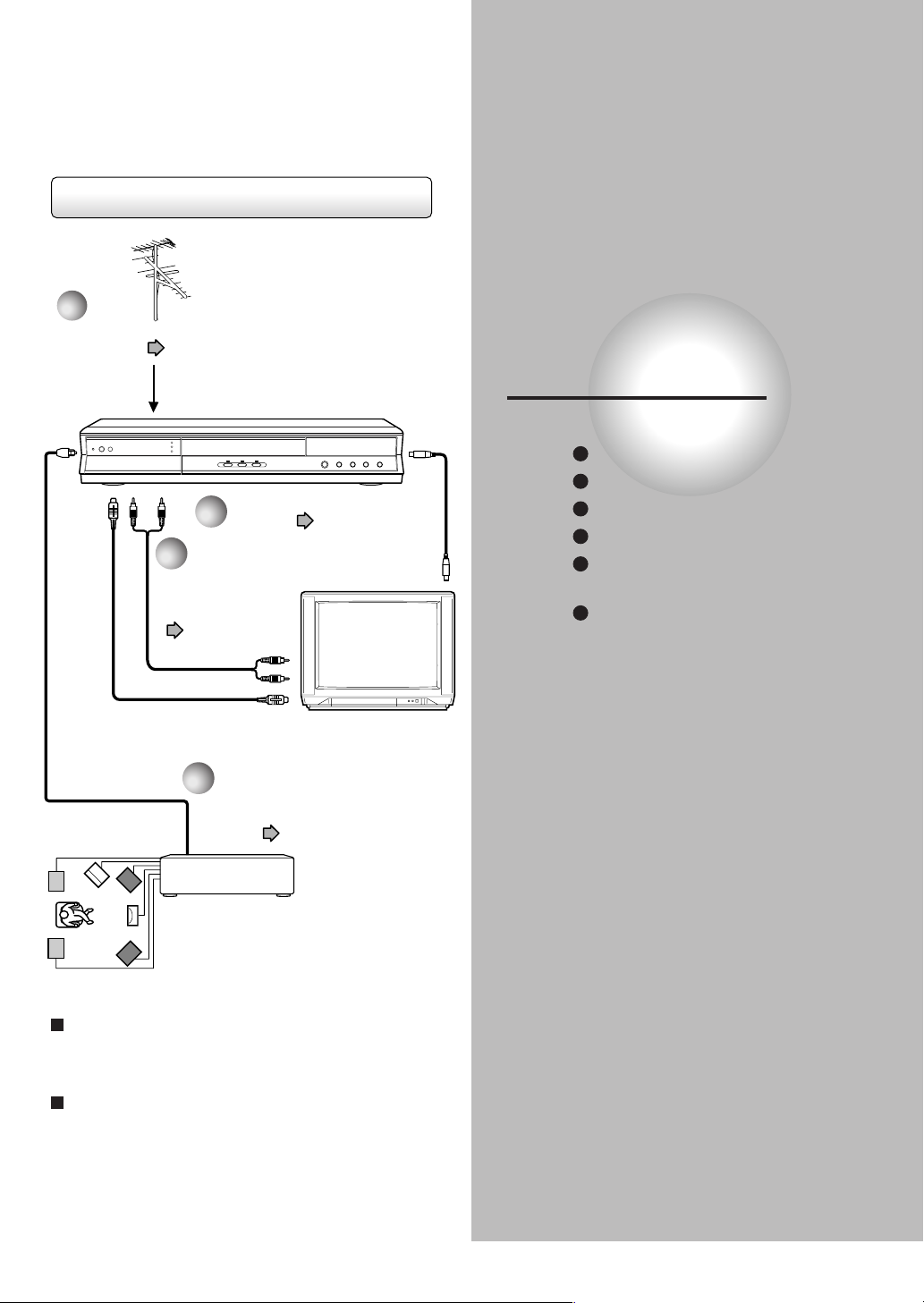
Connection procedure
1
“Connecting an antenna
and TV” ( page 14)
“Connecting an antenna
2
and TV” ( page 14)
3
“Connecting to a TV
equipped with
audio/video inputs”
( page 15)
Connections
Connect your recorder to your TV or stereo system.
Connecting an antenna and TV
Connecting to cable TV signal
Connecting to a satellite system
Connecting the IR control cable
Connecting to a TV equipped
with component video inputs
Connecting to an audio system
4
“Connecting to an audio
system” ( page 21)
AV amplifier
When you connect a TV equipped with audio/
video inputs
Perform steps 1, 2 and 3.
When you connect an audio system
Perform steps 1, 2, 3 and 4.
Page 14
Connections
D
I
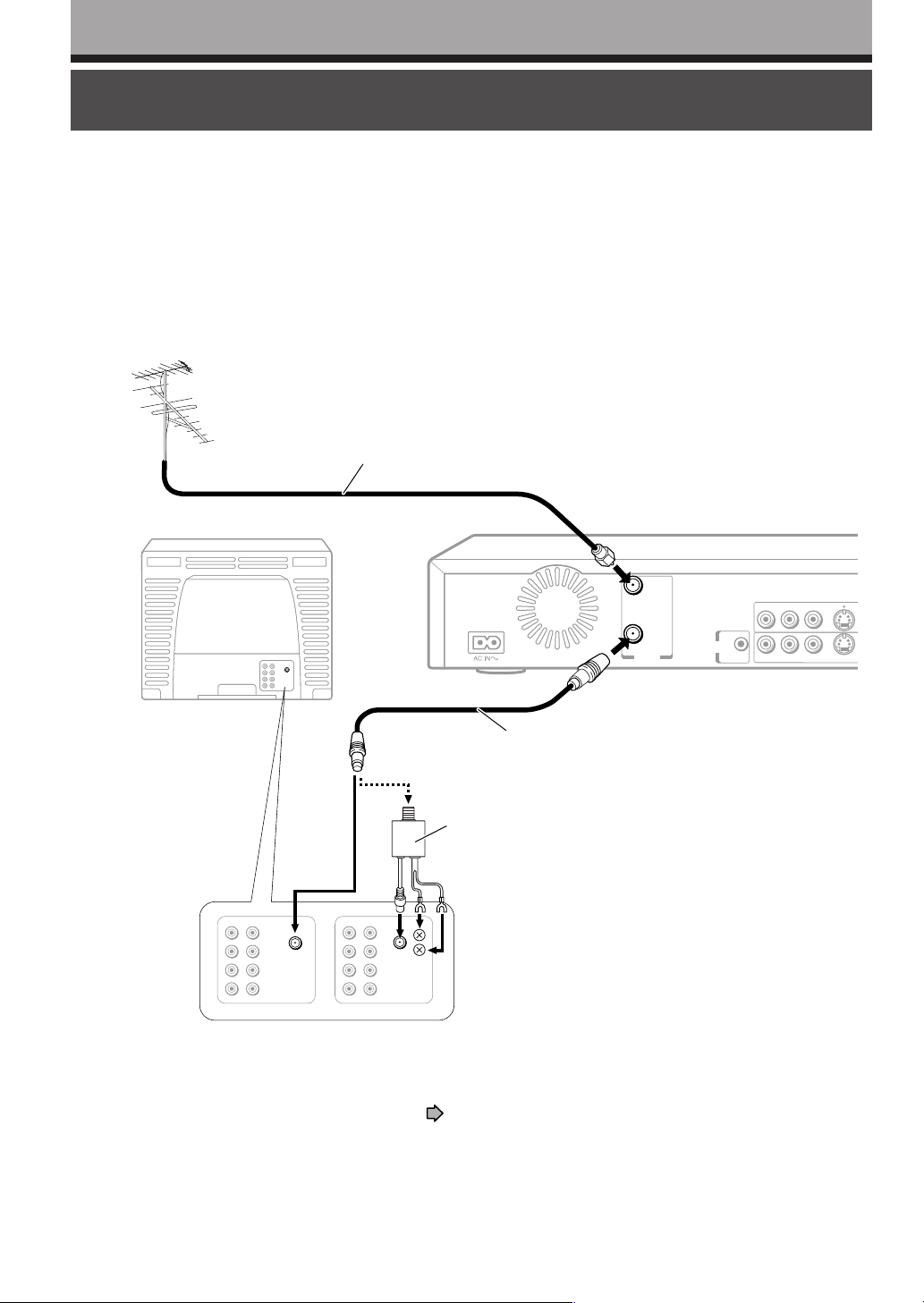
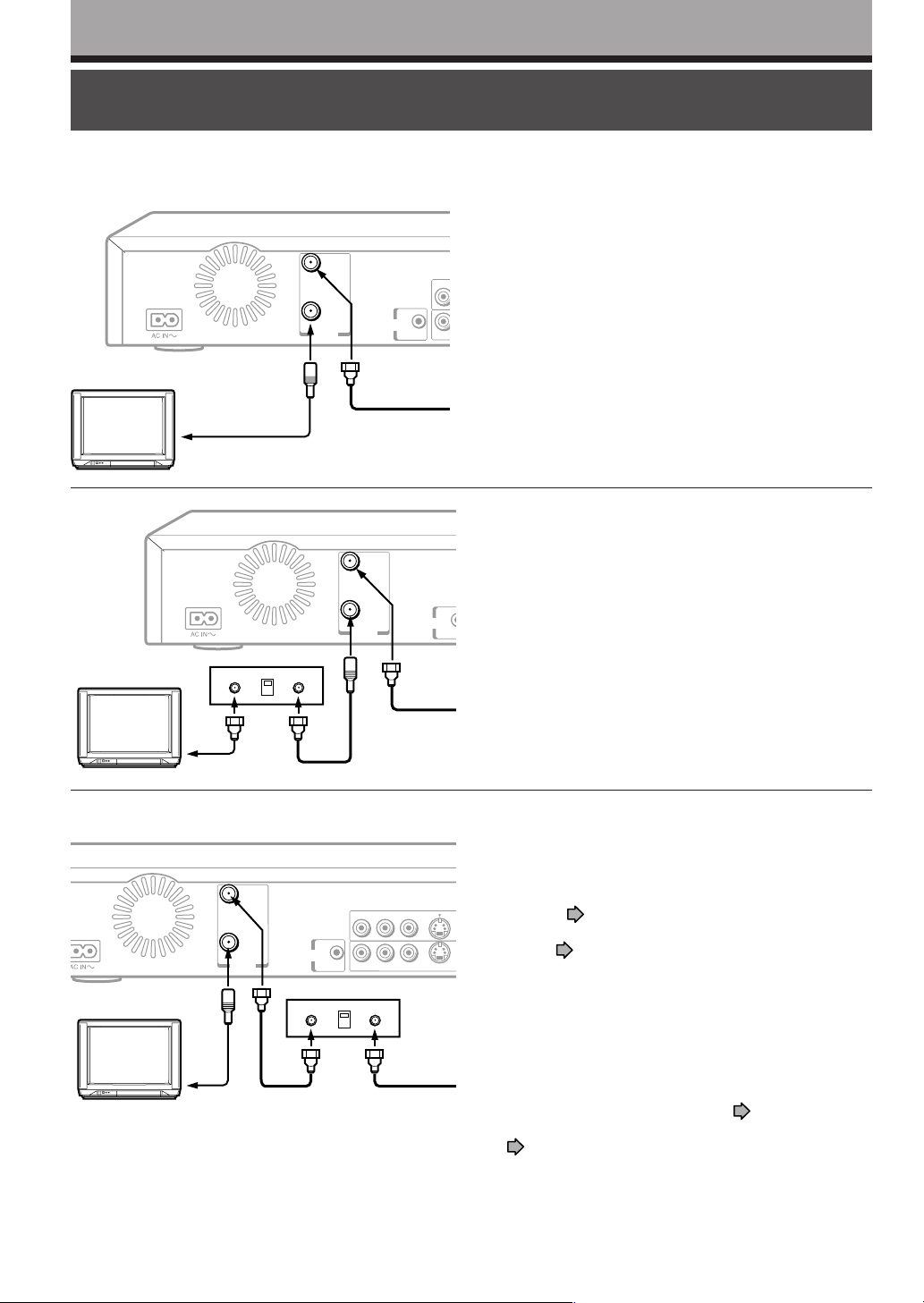
Connecting an antenna and TV
Connect your TV and the antenna to this recorder for recording and to view broadcast signals on the TV.
Disconnect the antenna cable from your TV, and connect it to the RF IN
(FROM ANT.) terminal on the recorder.
1
Using the supplied coaxial cable of this recorder, connect the RF OUT (TO
TV) terminal to the TV.
2
VHF/UHF antenna
Antenna cable (not supplied)
To RF IN (FROM ANT.)
TV
1
e.g.
VHF/UHF
2
To antenna input
RF IN
(FROM ANT.)
RF OUT
(TO TV)
VHF/UHF
CHANNEL
CHANGE
IR
To RF OUT (TO TV)
2
Coaxial cable (supplied)
Antenna splitter (not supplied)
Types of an antenna terminal may vary depending
on the TV.
Check the type on your TV, and connect properly
using either method as shown.
R L VIDEO
VIDEOLR
S-VI
S-VIDEO
For connecting to a cable box or a satellite system, see page 16 to 19.
Note
• This connection insures accessibility of broadcast signals to your TV only. Unlike a VCR, you can not assign channel 3 or 4
for playback of this recorder, because an antenna input only passes through in the recorder. You must connect this recorder
to a video input of your TV to enjoy playback picture from this recorder. (See the next page.)
14
Page 15
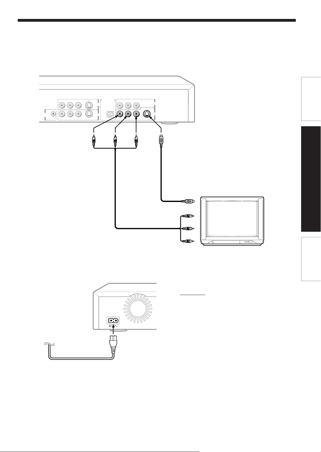
Connect to a TV equiped with audio/video inputs.
Connect as below for watching received channels or recorded contents. Watching via the RF OUT terminal
3
is not available.
DIGITAL AUDIO OUTPUT
S-VIDEO
BITSTREAM/PCM
INPUT1
INPUT3
S-VIDEO S-VIDEO
OPTICAL
P
R
P
B
Y
COMPONENT OUTPUT
OUTPUT
CHANNEL
CHANGE
IR
R L VIDEO
VIDEOLR VIDEORL
Introduction
(white)(red)
To OUTPUT
(R/L)
Video/audio cable (supplied)
(yellow)
To OUTPUT
(VIDEO)
To OUTPUT
(S-VIDEO)
S-Video cable (not supplied)
If the TV has an S-video input, connect the recorder
with an S-video cable. When using an S-video
cable, do not connect the yellow video cable.
To S-video input
To video inputs (yellow)
(white)
To audio input
(red)
Connect the power cord of the recorder to a wall outlet.
Make sure that the powered recorder lights the ON/STANDBY indicator on the front panel.
4
CAUTION
• Do not use any power cord other than the
supplied one.
• Do not use the supplied power cord with any
product other than this one.
Connections
TV or monitor with
audio/video inputs
Basic Setup
To wall outlet
Notes
• Refer to the owner’s manual of the connected TV as well.
• When you connect the recorder to your TV, be sure to turn off the power and unplug both units from the wall outlet before any
connections.
• If your television set has one audio input, connect the left and right audio outputs of the recorder to a Y cable adapter (not
supplied) and then connect to your TV.
• Connect the recorder directly to your TV. If you connect the recorder to a VCR, TV/VCR combination, video selector or AV
amplifier, the playback picture may be distorted due to copy protection.
15
Page 16
Connections
I
N
N
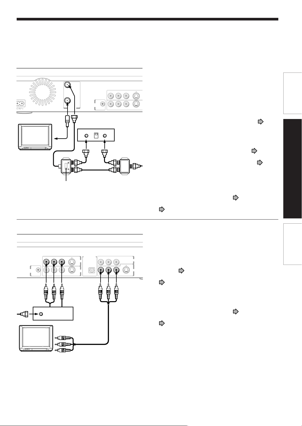
Connecting to cable TV signal
Choose one of the below according to your usage of the cable box.
For watching received channels, connect to the TV via the audio/video cable.
This set-up will allow you to:
– record an unscrambled channel.
– record an unscrambled channel while watching
R
another (only when you connect a cable-compatible
TV).
R
You will need to:
• to record a channel while watching another, select a
desired channel on the TV (only when you connect a
cable-compatible TV).
This set-up will allow you to:
– record an unscrambled channel.
– record an unscrambled channel while watching
another (scrambled or unscrambled).
You will need to:
• set TV channel to the output channel of the cable box.
• to record an unscrambled channel while watching a
scrambled channel, select a desired cable channel via
the cable box.
Cable box
3CH
4CH
RF IN
(FROM ANT.)
RF OUT
(TO TV)
VHF/UHF
CHANNEL
CHANGE
Incoming cable
RF IN
(FROM ANT.)
RF OUT
(TO TV)
VHF/UHF
IR
CHANNEL
CHANGE
OUT
RF IN
(FROM ANT.)
RF OUT
(TO TV)
VHF/UHF
IN
CHANNEL
CHANGE
Cable box
IR
3CH
4CH
Incoming cable
R L VIDEO
VIDEOLR
INOUT
Incoming cable
S-VIDEO
This set-up will allow you to:
– record any channels through the cable box.
You will need to:
• set “Cable Box/DBS” of “Set Top Box setting” to
S-VID
“C.Box”.
I
• set “Select input” of “Set Top Box setting”to “3CH” or
“4CH”.
I
page 37
page 37
• select a desired cable channel via the cable box.
• while the recorder is turned off, set TV channel to the
output channel of the cable box.
You can control cable channels from the recorder.
Preform the below.
1) Connect the supplied IR cable to the CHANNEL
CHANGE IR jack of the recorder.
page 19
2) Set “IR control” of “Set Top Box setting” to “On”.
page 37
16
Page 17
E
P
RF IN
(FROM ANT.)
RF OUT
(TO TV)
VHF/UHF
A/B switch
B
A
CHANNEL
CHANGE
Cable box
3CH
4CH
OUT
IR
R L VIDEO
VIDEOLR
IN
S-VIDEO
This set-up will allow you to:
– record an unscrambled or scrambled channel.
– record an unscrambled channel while watching
another unscrambled channel (only when you connect
a cable-compatible TV).
S-VID
IN
You will need to:
• A/B switch “A”: record an unscrambled channel which
IN
bypasses the cable box.
– set “Cable Box/DBS” of “Set Top
Box setting” to “Not used”.
37
• A/B switch “B”: record a scrambled or unscrambled
channel coming through the cable box.
– set “Cable Box/DBS” of “Set Top
Box setting” to “C.Box”.
– set “Select input” of “Set Top Box
setting”to “3CH” or “4CH”.
37
You can control cable channels from the recorder.
Preform the below.
1) Connect the supplied IR cable to the CHANNEL
CHANGE IR jack of the recorder.
page 19
2) Set “IR control” of “Set Top Box setting” to “On”.
page 37
page
page 37
page
Introduction
Connections
CHANNEL
CHANGE
IN
IR
DIGITAL AUDIO OUTPUT
R L VIDEO
S-VIDEO
INPUT1
INPUT3
VIDEOLR VIDEORL
S-VIDEO S-VIDEO
Cable box
BITSTREAM/PCM
OPTICAL
This set-up will allow you to:
Basic Setup
– watch or record a channel through the cable box via
the INPUT1 or INPUT3 (VIDEO/L/R) jacks.
R
P
P
B
Y
COMPONENT OUTPUT
You will need to:
• set “Cable Box/DBS” of “Set Top Box setting” to
OUTPUT
“C.Box”.
page 37
• set “Select Input” of “Set Top Box setting” to “Line1”.
page 37
You can control cable channels from the recorder.
Preform the below.
1) Connect the supplied IR cable to the CHANNEL
CHANGE IR jack of the recorder.
page 19
2) Set “IR control” of “Set Top Box setting” to “On”.
page 37
17
Page 18

Connections
N
N
Connecting to a satellite system
Choose one of the following according to your type of satellite receiver.
When the satellite receiver does not have audio/
video outputs
RF IN
(FROM ANT.)
RF OUT
(TO TV)
VHF/UHF
CHANNEL
CHANGE
Satellite receiver
OUT
IR
3CH
4CH
R L VIDEO
VIDEOLR
IN
Satellite antenna
S-VIDEO
1 Connect a satellite antenna to the satellite receiver.
2 Connect the RF IN (FROM ANT.) terminal on the
S-VID
recorder and the RF OUT terminal of the satellite
I
receiver.
3 Connect the RF OUT (TO TV) terminal on the recorder
I
and the antenna input connector of the TV.
You will need to:
• set “Cable Box/DBS” of “Set Top Box setting” to
“C.Box”.
page 37
• set “Select Input” of “Set Top Box setting”to “3CH” or
“4CH”.
page 37
You can control satellite channels from the recorder.
Preform the below.
1) Connect the supplied IR cable to the CHANNEL
CHANGE IR jack of the recorder.
page 19
2) Set “IR control” of “Set Top Box setting” to “On”.
page 37
Audio outputs
CHANNEL
CHANGE
IR
Satellite
receiver
R L VIDEO
IN
Satellite antenna
Video output
DIGITAL AUDIO OUTPUT
S-VIDEO
BITSTREAM/PCM
INPUT1
INPUT3
VIDEOLR VIDEORL
S-VIDEO S-VIDEO
OPTICAL
P
B
Y
R
P
COMPONENT OUTPUT
OUTPUT
When the satellite system has audio/video outputs
1 Connect a satellite antenna to the satellite system.
2 Connect the INPUT1 or INPUT3 (VIDEO/L/R) jacks on
the recorder and the audio/video output jacks of the
satellite system.
3 Connect the OUTPUT1 (VIDEO/L/R) jacks on the
recorder and the audio/video input jacks of the TV.
4 Connect the RF OUT (TO TV) terminal on the recorder
and the antenna input connector of the TV.
You will need to:
• set “Cable Box/DBS” of “Set Top Box setting” to
“C.Box”.
page 37
• set “Select Input” of “Set Top Box setting” to “Line1”.
page 37
You can control satellite channels from the recorder.
Preform the below.
1) Connect the supplied IR cable to the CHANNEL
CHANGE IR jack of the recorder.
page 19
2) Set “IR control” of “Set Top Box setting” to “On”.
page 37
18
Page 19

Connecting the IR control cable
D
The recorder sends commands to your connected set top box to control the channels of it through the IR control
cable. Make the following preparation.
Connect the plug of the supplied IR control cable to the CHANNEL CHANGE
IR jack on the recorder.
1
Place the transmitter near the set top box connected to the recorder.
2
RF IN
(FROM ANT.)
RLVI
RF OUT
(TO TV)
VHF/UHF
CHANNEL
CHANGE
1
IR
VIDLR
Cable box / satellite system
Introduction
Connections
Basic Setup
Transmitter
2
After connecting, make the necessary setting ( page 36).
When you use the recorder for the first time, also make the other settings (
Notes
• Do not connect an accessory other than the supplied IR control cable to the CHANNEL CHANGE IR jack.
• Do not cover the transmitter.
• The recorder sends commands even while it is turned off.
• Refer to the owner’s manual of the connected set top box as well.
Place as close as possible to the
signal sensor of the set top box.
page 28).
19
Page 20

Connections
Connecting to a TV equipped with component video inputs
If your TV has component video inputs, you can obtain pictures in better quality.
To P
B VIDEO OUT
CHANNEL
CHANGE
IR
To Y VIDEO OUT
DIGITAL AUDIO OUTPUT
R L VIDEO
S-VIDEO
INPUT1
INPUT3
VIDEOLR VIDEORL
S-VIDEO S-VIDEO
(red)
BITSTREAM/PCM
OPTICAL
Y
(white)
To P
P
R
P
B
TV or monitor equipped with
component video (INTERLACED/
PROGRESSIVE) inputs
To audio inputs of the
Audio cable (not supplied)
amplifier
(white)(red)
Component video outputs/inputs
Some TVs or monitors are equipped with component
video inputs. Connecting to these inputs allows you to
enjoy higher quality picture playback.
Actual labels for component video inputs may vary
depending on the TV manufacturer. (ex.Y, R-Y, R-B or
B, CR)
Y, C
In some TVs or monitors, the color levels of the
playback picture may be reduced slightly or the tint
may change. In such a case, adjust the TV or monitor
for optimum performance.
R VIDEO OUT
COMPONENT OUTPUT
OUTPUT
• Make the following setting.
On-screen display
“Audio out select”“Analog 2ch” page 42
Video cable
(not supplied)
R video input
To P
B video input
To P
To Y video input
Select
Page
To switch the output signal (Progressive/Interlaced)
PROGRESSIVE
Press PROGRESSIVE on the remote control.
The output signal alternates between
component progressive and component
interlaced.
Notes
• Refer to the owner’s manual of the connected TV as well.
• When you connect the recorder to other equipment, be sure to turn off the power and unplug all of the equipment from the
wall outlet before any connections.
• If you place the recorder near a tuner or radio, the radio broadcast sound might be distorted. In this event, place the recorder
away from the tuner and radio.
• The output sound of the recorder has a wide dynamic range. Be sure to adjust the audio amplifier’s volume to a moderate
listening level. Otherwise, the speakers and your hearing may be damaged by a sudden high volume sound.
• Turn off the amplifier before you connect or disconnect the recorder’s power cord. If you leave the amplifier power on, the
speakers may be damaged.
20
Page 21

Connections
Connecting to an audio system
You can enjoy high quality dynamic sounds by connecting the recorder to an audio system.
• For connection to your TV, see pages 14 to 15, 20.
• For details of output sound, see
“OPERATIONS”.
• This section uses the following reference marks.
Front speaker
Surround speaker
Sub woofer
Notes
• DO NOT connect the DIGITAL AUDIO OUTPUT
BITSTREAM/PCM jack of the recorder to the AC-3 RF
input of a Dolby Digital Receiver. This input on your A/V
Receiver is reserved for Laserdisc use only and is
incompatible with the DIGITAL AUDIO OUTPUT
BITSTREAM/PCM jack of the recorder.
• Connect the DIGITAL AUDIO OUTPUT BITSTREAM/PCM
jack of the recorder to the “OPTICAL” input of a Receiver
or Processor.
• Refer to the owner’s manual of the connected equipment
as well.
• When you connect the recorder to other equipment, be
sure to turn off the power and unplug all of the equipment
from the wall outlet before any connections.
• The output sound of the recorder has a wide dynamic
range. Be sure to adjust the audio amplifier’s volume to a
moderate listening level. Otherwise, the speakers and your
hearing may be damaged by a sudden high volume sound.
• Turn off the amplifier before you connect or disconnect the
recorder’s power cord. If you leave the amplifier power on,
the speakers may be damaged.
page 73 of
Center speaker
Signal flow
Caution
• When you are connecting (via the DIGITAL AUDIO
OUTPUT BITSTREAM/PCM jack) an AV decoder that
does not have Dolby Digital, Digital Theater Systems
(DTS) or MPEG2 decoding function, be sure to set
“Audio out select” to “PCM” from the on-screen displays
( page 42). Otherwise, high volume sound may
damage your hearing as well as the speakers.
• When playing DTS-encoded discs (DVD video discs
and audio CDs), excessive noise may be output from
the analog stereo jacks. To avoid possible damage to
the audio system, you should take proper precautions
when the analog audio out (L/R) jacks of the recorder
are connected to an amplification system. To enjoy
DTS Digital Surround™ playback, an external 5.1
channel DTS Digital Surround™ decoder system must
be connected to the DIGITAL AUDIO OUTPUT
BITSTREAM/PCM jack of the recorder.
Introduction
Connections
Basic Setup
21
Page 22

Connections
T
M
V
Connecting to an audio system (Continued)
Connecting to an amplifier equipped with a Dolby Digital decoder
Dolby Digital
Dolby Digital is the surround sound technology used in theaters showing the latest movies, and is now available to
reproduce this realistic effect in the home. You can enjoy motion picture and live concert DVD video discs with this
dynamic realistic sound by connecting the recorder to a 6 channel amplifier equipped with a Dolby Digital decoder or
Dolby Digital processor. If you have a Dolby Surround Pro Logic decoder, you will obtain the full benefit of Pro Logic
from the same DVD movies that provide full 5.1-channel Dolby Digital soundtracks, as well as from titles with the Dolby
Surround mark.
ANT.)
UT
V)
F
CHANNEL
CHANGE
R L VIDEO
IR
DIGITAL AUDIO OUTPUT
S-VIDEO
BITSTREAM/PCM
PB
Y
INPUT1
INPUT3
VIDEOLR VIDEORL
OPTICAL
S-VIDEO S-VIDEO
P
R
COMPONENT OUTPUT
OUTPUT
Amplifier equipped with a
Dolby Digital decoder
To OPTICAL type
digital audio input
To DIGITAL AUDIO OUTPUT
BITSTREAM/PCM
Optical digital cable (not supplied)
• Use DVD video discs encoded via the Dolby Digital recording system.
• Make the following setting.
On-screen display
“Audio out select”
Recording system
Select:
“Bitstream”
D
Page
page 42
page 71,
“OPERATIONS”
Manufactured under license from Dolby Laboratories. “Dolby”
and the double-D symbol are trademarks of Dolby Laboratories.
Connecting to an amplifier equipped with Dolby Surround Pro Logic
Dolby Surround Pro Logic
You can enjoy the dynamic realistic sound of Dolby Surround Pro Logic by connecting an amplifier and speaker system
(right and left front speakers, a center speaker, and one or two rear speakers).
With an amplifier equipped with Dolby Digital
Connect the equipment the same way as described in “Connecting to an amplifier equipped with a Dolby Digital
decoder”. Refer to that amplifier’s owner’s manual and set the amplifier so you can enjoy Dolby Surround Pro Logic
sound.
With an amplifier not equipped with Dolby Digital
Connect the equipment as follows.
ANT.)
T
)
CHANNEL
CHANGE
R L VIDEO
IR
DIGITAL AUDIO OUTPUT
S-VIDEO
BITSTREAM/PCM
P
B
Y
INPUT1
INPUT3
VIDEOLR VIDEORL
OPTICAL
S-VIDEO S-VIDEO
P
R
COMPONENT OUTPUT
OUTPUT
Amplifier equipped with
Dolby Surround Pro Logic
To audio input
*
To OUTPUT (L/R)
Audio cable (not supplied)
• Make the following setting.
On-screen display
Select:
“Audio out select”“Analog 2ch” page 42
Be sure to set “Audio out select” to “Analog 2ch”
when you enjoy sounds of Dolby Surround Pro Logic
Page
* Connect one or two rear speakers.
The output sound from the rear speakers will be monaural
even if you connect two rear speakers.
using this connection.
22
Page 23

Connecting to an amplifier equipped with a DTS decoder
O
R
Digital Theater Systems (DTS)
DTS is a high quality surround technology used in theaters and now available for home use, on DVD video discs or
audio CDs.
If you have a DTS decoder or processor, you can obtain the full benefit of 5.1 channel DTS encoded sound tracks on
DVD video discs or audio CDs.
IN
OM ANT.)
OUT
TV)
HF
CHANNEL
CHANGE
R L VIDEO
IR
S-VIDEO
INPUT1
INPUT3
VIDEOLR VIDEORL
S-VIDEO S-VIDEO
To DIGITAL AUDIO OUTPUT
BITSTREAM/PCM
DIGITAL AUDIO OUTPUT
BITSTREAM/PCM
OPTICAL
P
R
P
B
Y
COMPONENT OUTPUT
OUTPUT
Optical digital cable (not supplied)
To OPTICAL type
digital audio input
Amplifier equipped with a
DTS decoder
• Use DVD video discs or audio CDs encoded via the DTS recording system.
• Make the following setting.
On-screen display
“Audio out select”
Recording system
Select
“Bitstream”
DTS
Page
page 42
page 71,
“OPERATIONS”
“DTS” and “DTS Digital Out” are trademarks of Digital Theater
Systems, Inc.
Connecting to an amplifier equipped with an MPEG2 audio decoder
MPEG2 sound
You can enjoy motion picture and live concert DVD video discs with dynamic realistic sound by connecting an amplifier
equipped with an MPEG2 audio decoder or MPEG2 audio processor.
Introduction
Connections
Basic Setup
RF IN
(FROM ANT.)
RF OUT
(TO TV)
/UHF
CHANNEL
CHANGE
R L VIDEO
IR
DIGITAL AUDIO OUTPUT
S-VIDEO
BITSTREAM/PCM
Y
INPUT1
INPUT3
VIDEOLR VIDEORL
OPTICAL
S-VIDEO S-VIDEO
P
R
P
B
COMPONENT OUTPUT
OUTPUT
To DIGITAL AUDIO OUTPUT
BITSTREAM/PCM
Optical digital cable (not supplied)
• Use DVD video discs encoded via the MPEG2 recording system.
• Make the following setting.
On-screen display
“Audio out select”
Recording system
Select
“Bitstream”
MPEG2
Page
page 42
page 71,
“OPERATIONS”
Amplifier equipped with an
MPEG2 audio decoder
To OPTICAL type
digital audio input
23
Page 24

Connections
Connecting to an audio system (Continued)
Connecting to an amplifier equipped with a digital audio input
2 channel digital stereo
You can enjoy the dynamic sound of 2 channel digital stereo by connecting an amplifier equipped with a digital audio
input and speaker system (right and left front speakers).
RF IN
HF/UHF
(FROM ANT.)
RF OUT
(TO TV)
CHANNEL
CHANGE
R L VIDEO
IR
DIGITAL AUDIO OUTPUT
S-VIDEO
BITSTREAM/PCM
P
Y
INPUT1
INPUT3
VIDEOLR VIDEORL
OPTICAL
S-VIDEO S-VIDEO
P
R
B
COMPONENT OUTPUT
To DIGITAL AUDIO OUTPUT
BITSTREAM/PCM
Optical digital cable (not supplied)
• Make the following setting.
On-screen display
Select
“Audio out select”“PCM” page 42
Page
OUTPUT
Amplifier equipped with
a digital audio input
To OPTICAL type
digital audio input
24
Page 25

Basic Setup
Read this chapter for necessary settings to get started.
When you use this recorder for the first time, be sure to
perform A to C in this order.
Proceed to D if necessary.
Starting up the recorder
A: Initial settings
Language setting
Time and date setting
Channel setting
Set top box setting
Guide channel setting
B: Output sound setting
C: TV shape setting
D: Remote control settings
Operating a TV with the
remote control of
this recorder
Operating the second and
third TOSHIBA DVD video
recorders with the remote
control of this recorder
Page 26

Basic Setup
Starting up the recorder
While the icon is flashing, the recorder is checking
After all the necessary connections,
• Turn on the equipment connected to the
recorder.
• Select the corresponding video input on
your television.
Perform these selections whenever you operate
the recorder.
Turning the power on
Press the ON/STANDBY button from the remote
control or on the front panel of the recorder.
ON/STANDBY button
the status and reading data of the DVD drive for
startup. If the DVD drive does not contain a disc,
the recorder consumes less time to startup,
because it does not need to read data from the
DVD drive.
While the “Loading” icon is flashing, the recorder
cannot respond to any operations of buttons other
than CHANNEL and INPUT SELECT. Operate all
other functions after the icon has disappeared.
Note
• When the recorder is turned on for the first time, the
following menu will be displayed after the “Loading” icon
has disappeared. See “A: Initial settings” ( page 28).
e.g.
Language
Time & Date setting
TV/Cable
Channel setting
Guide channel setting
Set Top Box setting
Initial settings
English
TV
ON/STANDBY indicator
OPEN/CLOSE
TOP MENU
ANGLE
LIBRARY
W
O
L
S
DVD
MENU
RETURN
SUBTITLE
AUDIO
TIMESLIP
INSTANT REPLAY
EASY
NAVI
REC MENU EDIT MENU
CONTENT MENU
ON/STANDBY button
CHANNEL
INSTANT SKIP
S
K
I
P
When the power turns on, the ON/STANDBY indicator
changes color from red (standby mode) to green
(operation).
After a few seconds, a startup screen appears.
The following icon will appear on the top right corner
of the screen. The icon will continue flashing
momentarily.
e.g.
Loading
Turning the power off
Press the ON/STANDBY button from the remote
control or on the front panel of the recorder.
The “Unloading” icon appears on the right corner of
the top of the screen, and the ON/STANDBY indicator
turns red. Then the power turns off.
Note
• If the recorder freezes for about 15 minutes and will not
respond to any buttons, holding down the ON/STANDBY
button on the front panel for about 10 seconds can force
the recorder to turn off. However, this is an emergency
measure, which contains a risk of damage to data or discs.
Avoid casual use of this measure.
26
Page 27

Startup/finishing (closing) icons
These icons are displayed on the right corner on the
top of the screen. While they are flashing, the recorder
is operating as follows:
Startup, reading a disc, finishing recording
Loading
Unloading a disc, finishing the recorder’s
Un
loading
operation
Opening a disc tray
Open
Close
Closing a disc tray
Introduction
Connections
Basic Setup
27
Page 28

Basic Setup
A: Initial Settings
This step sets the recorder’s clock and tuner to record broadcasting TV programs.
Once you complete this process there is generally no need to reset the clock. (However, if there are
discrepancies in the recorder’s time display or changes made to receivable TV stations, you should
make this setting again.)
OPEN/CLOSE
DVD
MENU
TOP MENU
ANGLE
LIBRARY
W
O
L
S
F
R
A
M
E
/
A
D
J
REC
REC
VCR Plus+
456
789
SETUP ENTER
RETURN
SUBTITLE
TIMESLIP
EASY
NAVI
REC MENU EDIT MENU
ENTER
U
S
T
REC MODE
EXTEND
0
AUDIO
312
+
10
CHANNEL
INSTANT SKIPINSTANT REPLAY
CONTENT MENU
S
K
I
P
H
C
R
A
E
S
E
R
U
T
C
I
P
PLAYSTOPPAUSE
QUICK MENU
TV CODE
T.SEARCH
CLEAR
DELETE
When the recorder is operated for the first time, begin
from step 3.
Press SETUP.
1
Press / to select “Initial settings”, then press
ENTER.
2
e.g.
ENTER
Language
Time & Date setting
TV/Cable
Channel setting
Guide channel setting
Set Top Box setting
Initial settings
English
TV
Press / to select the setting to be adjusted,
then press ENTER.
3
The submenu appears.
e.g. When “Time & Date setting” is selected:
ENTER
e.g.
Language
Time & Date setting
TV/Cable
Channel setting
Guide channel setting
Set Top Box setting
Initial settings
English
TV
Auto
Manual
When the recorder is operated for the first time, input
settings in the following order.
Open the lid.
1: Language setting
2: Time and date setting
3: Channel setting
4: Set top box setting
5: Guide channel setting
page 30
page 31
page 34
page 36
page 40
Notes
• To go back to the previous menu, press the button.
• To exit the menu, press the SETUP button.
• If you exit the “Initial settings” menu without setting the clock and channels, a menu may automatically appear to remind you
to set them each time you turn on the recorder. Once you complete this process, the menu reminder will not appear again.
28
Page 29

Tip on setting
The recorder provides you with a variety of GUI
(Graphical User Interface) displays to perform key
operations including customizing of setting, playback
or recording.
Refer to the guide on the bottom on each GUI for
further programming related information.
e.g.
Initial settings
Language
Time & Date setting
TV/Cable
Channel setting
Guide channel setting
Set Top Box setting
English
TV
If a message appears
The recorder may display a message. Each message
varies according to operational status.
To respond, follow the below examples.
Message
e.g.
message
OK
Introduction
Direction buttons
O button
ENTER button
SETUP
SETUP button
Return
SetSelect
Operation guide
FunctionExample of the icon
To select an item.
To return to the previous
page.
To enter (confirm) a
selected item or setting.
To display/exit a setting
menu.
SETUP
SETUP
Exit
e.g.
Set
Select either response (by
Connections
highlighting in green) using the
message
OK
Yes
No
/ buttons, then press the
ENTER button.
The message disappears.
2 selections
Basic Setup
e.g.
message
OK
1 selection
e.g.
message
Read the message, then press
the ENTER button.
The message disappears.
The message disappears
automatically in a few seconds.
No selection
29
Page 30

Basic Setup
A: Initial Settings (Continued)
1: Language setting
Select a preferred language for on-screen displays.
When the recorder is operated for the first time, begin
OPEN/CLOSE
TOP MENU
ANGLE
DVD
MENU
SUBTITLE
RETURN
AUDIO
CHANNEL
from step 3.
1
Press SETUP.
TIMESLIP
EASY
NAVI
REC MENU EDIT MENU
LIBRARY
W
O
L
S
ENTER
F
R
A
M
E
/
A
D
J
U
S
T
REC
REC
VCR Plus+
456
789
SETUP ENTER
EXTEND
0
REC MODE
312
+
10
INSTANT SKIPINSTANT REPLAY
CONTENT MENU
S
K
I
P
H
C
R
A
E
S
E
R
U
T
C
I
P
PLAYSTOPPAUSE
QUICK MENU
TV CODE
T.SEARCH
CLEAR
DELETE
Press / to select “Initial settings”, then press ENTER.
2
Press / to select “Language”, then press
ENTER.
3
e.g.
ENTER
Language
Time & Date setting
TV/Cable
Channel setting
Guide channel setting
Set Top Box setting
Initial settings
English
TV
English
French
Press / to select a language, then press
ENTER.
4
English: To view on-screen displays in English.
ENTER
French : To view on-screen displays in French.
Open the lid.
“1: Language setting” is complete. Go to “2: Time and date setting”. ( page 31)
30
Page 31

2: Time and date setting
Set the recorder’s clock. If it is not set correctly, the recorder cannot perform operations other than playback.
When the recorder is operated for the first time, begin
OPEN/CLOSE
TOP MENU
ANGLE
DVD
MENU
SUBTITLE
RETURN
AUDIO
CHANNEL
from step 3.
Press SETUP.
1
Introduction
TIMESLIP
EASY
NAVI
REC MENU EDIT MENU
LIBRARY
W
O
L
S
ENTER
F
R
A
M
E
/
A
D
J
U
S
T
REC
REC
VCR Plus+
456
789
SETUP ENTER
EXTEND
0
REC MODE
312
+
10
INSTANT SKIPINSTANT REPLAY
CONTENT MENU
S
K
I
P
H
C
R
A
E
S
E
R
U
T
C
I
P
PLAYSTOPPAUSE
QUICK MENU
TV CODE
T.SEARCH
CLEAR
DELETE
Press / to select “Initial settings”, then press ENTER.
2
Press / to select “Time & Date setting”,
then press ENTER.
3
e.g.
ENTER
Language
Time & Date setting
TV/Cable
Channel setting
Guide channel setting
Set Top Box setting
Initial settings
English
TV
Auto
Manual
Press / to select “Auto” or “Manual”, then
press ENTER.
4
Auto : The recorder will set the time and date.
ENTER
Proceed to step 5.
(This is not a self-correcting function.)
Manual : You can set the clock manually. See “Manual
clock setting”
page 33
Select “Manual” to set the clock if not set correctly by
“Auto”.
Auto clock setting
Connections
Basic Setup
Open the lid.
Press / to select an item, then press /
to select a detailed setting.
5
e.g.
ENTER
Auto clock set
Summer time
Use
Time zone
Auto
Channel
Auto
31
Page 32

Basic Setup
A: Initial Settings (Continued)
Notes on summer time on this recorder
• The recording system of this recorder always conforms to its own actual clock even at the moment it gains or loses 1 hour of
shift to/from summer time. Therefore, there may be some inconsistency in the display’s digits or actual operations on that
occasion. For example, on the first Sunday in April, the actual recording length of a programmed recording from 1:00 a.m. to
4:00 a.m. will be 2 hours, not 3. Be sure to give a careful consideration to your setting or reading on-screen if a recording
period includes the moment of time shift.
• This recorder’s clock cannot lose 1 hour on the last Sunday in October even if you set “Auto” or “Use” at step 5, unless it
once gained 1 hour in April.
1) Set “Summer time (Daylight-Saving time)”.
OPEN/CLOSE
TOP MENU
ANGLE
DVD
MENU
SUBTITLE
RETURN
AUDIO
CHANNEL
DST start :Daylight-saving time begins on the first Sunday in April. The
internal clock automatically changes from 2:00 AM to 3:00 AM (forward
one hour).
DST end :Daylight-saving time ends on the last Sunday in October. At 2:00
AM the recorder clock automatically changes to 1:00 AM (back one hour).
TIMESLIP
EASY
NAVI
REC MENU EDIT MENU
LIBRARY
W
O
L
S
ENTER
F
R
A
M
E
/
A
D
J
U
S
T
REC
REC
VCR Plus+
456
789
SETUP ENTER
EXTEND
0
REC MODE
312
+
10
INSTANT SKIPINSTANT REPLAY
CONTENT MENU
S
K
I
P
H
C
R
A
E
S
E
R
U
T
C
I
P
PLAYSTOPPAUSE
QUICK MENU
TV CODE
T.SEARCH
CLEAR
DELETE
Auto : The recorder uses clock data Broadcast by the local
(PBS) TV stations.
Use : You want to use the DST function, and you are living
in an area that applies Daylight-saving time.
No Use : You are not living in the area where Daylight-saving
time applies and you do not want to use DST function.
2) Set “Time zone”.
If you select “Auto” for your time zone, the recorder sets the clock
using the first Coordinated Universal Time information it finds. If
the auto set time is not correct, select another time zone or use
the “Manual” option.
3) Set “Channel”.
buttons are also available to change it.)
(When displaying a channel number, the number
If you do not know the clock data channel, select “Auto”. The
recorder will scan automatically to tune the channel carrying the
clock data. (generally a PBS station)
If you select this when “IR control” is “On” (
page 37), the
recorder searches 1 - 70 ch of the set top box connected to the
input which you set at “Select input” (
• Depending on the signal condition, the recorder may take a longer time to
set the clock.
page 37).
Select “Channel” to set the clock if not set correctly by “Auto”.
Press ENTER.
6
The clock setting starts. The display returns to the
ENTER
previous screen after setting is completed.
Auto Clock Setting may take a long time.
If Auto clock setting is unsuccessful, input the time and
date via the “Manual” clock setting menu selection.
Notes
• If you set “Summer time (Daylight-Saving time)” to “Auto” and “Time zone” to “Manual”, a small time discrepancy may occur
around the hours of DST start/end.
• Even if “Time & Date setting” is set to “Auto,” a time discrepancy within 1 second should be inevitable.
• When setting both “Time & Date setting” and “Time zone” to “Auto”, you can confirm the set “Time zone” in the “Time zone”
display of the “Manual” screen in “Time & Date setting”. (The “Time zone” display of the “Manual” screen in “Time & Date
setting” will remain in “Auto”.)
• In the case of a programmed recording with the DST change-over point to Daylight-saving time, if the continuous recording
time exceeds the limit due to a time discrepancy caused by Daylight-saving time during recording, the recording stops on
that point.
32
Page 33

OPEN/CLOSE
TOP MENU
ANGLE
LIBRARY
W
O
L
S
F
R
A
M
E
/
A
D
J
U
S
REC
REC
DVD
MENU
RETURN
SUBTITLE
AUDIO
TIMESLIP
EASY
NAVI
REC MENU EDIT MENU
ENTER
T
CHANNEL
INSTANT SKIPINSTANT REPLAY
CONTENT MENU
S
K
I
P
H
C
R
A
E
S
E
R
U
T
C
I
P
PLAYSTOPPAUSE
QUICK MENU
Manual clock setting
Select “Manual” at step 4 page 31.
e.g.
Manual clock set
Year
Time
Date
3 / 21 (Su) 6 : 152004
Time zone
Summerampm
Hawaii
Usepm
Press / and ADJUST ( / ) to set the
clock.
4
/ buttons:
ENTER
F
R
A
M
E
/
A
D
J
U
S
T
To select “Year”, “Date”, “Time”, “am/pm”, “Summer
(Summer time)” or “Time zone”.
ADJUST (
/ ) buttons:
To change the data.
/ buttons can also be used in addition to ADJUST
(
/ ) buttons.)
(
Introduction
Connections
VCR Plus+
456
789
SETUP ENTER
EXTEND
0
REC MODE
312
+10
TV CODE
T.SEARCH
CLEAR
DELETE
After setting all the items, press ENTER.
5
The following message appears.
ENTER
Set date and time?
Yes No
Press / to select “Yes”, then press ENTER.
6
SETUP
ENTER
Notes
• This recorder is provided with a calendar extending to 2069. (However, this does not mean that the recorder is supported to
2069.)
• To go back to the previous menu, press the button.
• To exit the menu, press the SETUP button.
The “Initial Settings” menu returns.
Basic Setup
“1: Time and date setting” is complete. Go to “3: Channel setting”. ( page 34)
33
Page 34

Basic Setup
A: Initial Settings (Continued)
3: Channel setting
The recorder scans through all receivable TV and cable channels and stores only the active ones in its memory.
Once this process is completed, you can select a desired channel using the CHANNEL buttons.
OPEN/CLOSE
DVD
MENU
TOP MENU
ANGLE
LIBRARY
W
O
L
S
F
R
A
M
E
/
A
D
J
REC
REC
VCR Plus+
456
789
SETUP ENTER
RETURN
SUBTITLE
TIMESLIP
EASY
NAVI
REC MENU EDIT MENU
ENTER
U
S
T
REC MODE
EXTEND
0
+10
AUDIO
312
CHANNEL
INSTANT SKIPINSTANT REPLAY
CONTENT MENU
S
K
I
P
H
C
R
A
E
S
E
R
U
T
C
I
P
PLAYSTOPPAUSE
QUICK MENU
TV CODE
T.SEARCH
CLEAR
DELETE
When the recorder is operated for the first time, begin
from step 3.
Press SETUP.
1
Press / to select “Initial settings”, then press ENTER.
2
Press / to select “TV/Cable”, then press
ENTER.
3
e.g.
ENTER
Language
Time & Date setting
TV/Cable
Channel setting
Guide channel setting
Set Top Box setting
Initial settings
English
Auto
TV
TV
Cable
Press / to select “TV” or “Cable”, then
press ENTER.
4
TV : To store broadcast channels received via the
antenna.
ENTER
Cable : To store channels received via cable.
Press / to select “Channel setting”, then
press ENTER.
5
e.g.
34
Open the lid.
ADJUST
ENTER
Language
Time & Date setting
TV/Cable
Channel setting
Guide channel setting
Set Top Box setting
Initial settings
English
Auto
TV
Auto
Manual
Page 35

Press / to select “Auto”, then press
ENTER.
6
ENTER
Adding or erasing channels
Adding channels
If a desired channel cannot be scanned automatically
because of a weak signal, it can be added to the
memory.
Erasing channels
You can erase a stored channel from the memory.
1) Select “Manual” at step 6.
2) Press
or erase.
For cable channels, refer to the chart below page.
3) Press ADJUST (
“Erase”.
Add : Adding channels
Erase : Erasing channels
/ to select a channel you want to add
/ ) to select “Add” or
The recorder starts scanning and active channels are
stored in the recorder in ascending order.
The display returns to the previous screen after setting
is completed.
e.g.
Channel set Cable manual 1/13
Home CH Add/Erase
Add
1
Erase
2
Erase
3
Erase
4
Add
5
Erase
6
Erase
7
Add
8
Erase
9
Erase
10
4) Press ENTER.
The confirmation message appears.
Press the
/ buttons to select “Ye s ”, then press
the ENTER button.
Introduction
Connections
Basic Setup
Channel reference
Number on the recorder CH NUMBER 1 2 3456789
Corresponding channel number TV – 23456789
Ccable STD (HRC/IRC) 1
10 11 12 13 14 15 16 17 18 19 20 21 22 23 24 25 26 27 28 29 30
10 11 12 13 14 15 16 17 18 19 20 21 22 23 24 25 26 27 28 29 30
10 11 12 13 A B C D E F G H I J K L M N O P Q
31 32 33 34 35 36 37 38 39 40 41 42 43 44 45 46 47 48 49 50 51
31 32 33 34 35 36 37 38 39 40 41 42 43 44 45 46 47 48 49 50 51
R S T U V W AA BB CC DD EE FF GG HH II JJ KK LL MM NN OO
52 53 54 55 56 57 58 59 60 61 62 63 64 65 66 67 68 69 70 71 …
52 53 54 55 56 57 58 59 60 61 62 63 64 65 66 67 68 69 ––…
PP QQ RR SS TT UU VV WW XX YY ZZ AAA BBB 65 66 67 68 69 70 71 …
93 94 95 96 97 98 99 100 101 102 103 … 121 122 123 124 125
–––––––––––…–––––
93 94 A-5 A-4 A-3 A-2 A-1 100 101 102 103 … 121 122 123 124 125
Cable signals
• STD (standard) cable TV signals
• HRC (Harmonic Related Carriers) cable TV signals
• IRC (Incremental Related Carriers) cable TV signals
IRC is also called ICC (Incremental Coherent Carriers)
“3: Channel setting” is complete. Go to “4: Set top box setting”. ( page 36)
(A-8)
2345
(A-7)6(A-6)
789
35
Page 36

Basic Setup
S
K
O
W
N
N
A: Initial Settings (Continued)
4: Set top box setting
For connecting a cable box or a satellite receiver to this recorder, follow the instructions below:
Preparation:
• To control channels of the connected set top box from the recorder, connect the supplied IR control cable to the
CHANNEL CHANGE IR jack of the recorder. (
• Confirm which type your connection is.
page 19)
Type A
VHF/UHF
RF IN
(FROM ANT.)
RF OUT
(TO TV)
CHANNEL
CHANGE
IR
3CH
4CH
R L VIDEO
S-VID
I
I
VIDEOLR
S-VIDEO
Cable box or
satellite
Type B
CHANNEL
CHANGE
R L VIDEO
VIDEOLR VIDEORL
IR
DIGITAL AUDIO OUTPUT
S-VIDEO
BITSTREAM/PCM
INPUT1
INPUT3
OPTICAL
S-VIDEO S-VIDEO
R
P
PB
Y
COMPONENT OUTPUT
OUTPUT
system
INOUT
Incoming cable
I
L
S
P
When the recorder is operated for the first time, begin
IN
Cable box
or satellite
system
from step 3.
ENTER
F
R
A
M
E
/
A
D
J
U
S
T
REC
REC
A
E
S
E
R
U
T
C
I
P
PLAYSTOPPAUSE
QUICK MENU
H
C
R
Press SETUP.
1
Press / to select “Initial settings”, then press ENTER.
2
Press / to select “Set Top Box setting”,
then press ENTER.
3
36
VCR Plus+
EXTEND
REC MODE
456
789
SETUP ENTER
+
0
Open the lid.
312
10
TV CODE
T.SEARCH
CLEAR
DELETE
e.g.
ENTER
Set Top Box setting
Cable Box/ DBS
Select Input
IR control
Brand type
Not used
3CH
Off
0 0 0
Page 37

OPEN/CLOSE
TOP MENU
ANGLE
EASY
NAVI
REC MENU EDIT MENU
LIBRARY
W
O
L
S
DVD
MENU
SUBTITLE
TIMESLIP
RETURN
AUDIO
CHANNEL
INSTANT SKIPINSTANT REPLAY
CONTENT MENU
S
K
I
P
Press ADJUST (or / ) to select your set top
box connected to this recorder.
4
If you do not connect a set top box, select “Not used”
F
R
A
M
E
/
A
D
J
U
S
T
then press the ENTER button. Skip to step 9.
C.Box: When a cable box is connected.
DBS: When a satellite system is connected.
Press .
Introduction
ENTER
F
R
A
M
E
/
A
D
J
U
S
T
REC
REC
VCR Plus+
456
789
SETUP ENTER
EXTEND
0
REC MODE
312
+10
A
E
S
E
R
U
T
C
I
P
PLAYSTOPPAUSE
QUICK MENU
TV CODE
T.SEARCH
CLEAR
DELETE
5
Connections
e.g.
H
C
R
ENTER
Set Top Box setting
Cable Box/ DBS
Select Input
IR control
Brand type
C.Box
3CH
Off
0 0 0
Press ADJUST (or / ) to select the way of
signal input from the set top box.
6
Basic Setup
3CH : For type A connection with the output channel
F
R
A
M
E
/
A
D
J
U
S
T
4CH : For type A connection with the output channel
number 3 of the set top box.
number 4 of the set top box.
Line1 : For type B connection via the INPUT1 jacks
using the audio/video cable.
Line3 : For type B connection via the INPUT3 jacks
using the audio/video cable.
Press , then press ADJUST (or / ) to
select “Off” or “On”.
7
F
R
A
ENTER
M
E
/
A
D
J
U
S
T
Off : Channels of the set top box are selected by its
own selector. Skip to step 9.
On : The reocrder can change channels of the set
top box.
(Be sure to make the connection to the
CHANNEL CHANGE IR jack (
page 19). If
you make timer program recording, keep the set
top box powered on to have it receive
commands from the recorder.)
(Continued)
37
Page 38

Basic Setup
A: Initial Settings (Continued)
TIMESLIP
EASY
NAVI
REC MENU EDIT MENU
LIBRARY
W
O
L
S
ENTER
F
R
A
M
E
/
A
D
J
U
S
T
REC
REC
VCR Plus+
456
789
SETUP ENTER
EXTEND
0
REC MODE
312
+
10
INSTANT SKIPINSTANT REPLAY
CONTENT MENU
S
K
I
P
H
C
R
A
E
S
E
R
U
T
C
I
P
PLAYSTOPPAUSE
QUICK MENU
TV CODE
T.SEARCH
CLEAR
DELETE
Press , then press the number buttons to
enter the 3 digits of a brand code of your set
8
top box obtained from the table (
e.g. If you connect a TOSHIBA satellite receiver:
ENTER
123
456
789
0
0 09
Press ENTER.
9
The “Initial settings” menu returns.
ENTER
Press SETUP.
10
The “Initial settings” menu disappears.
page 39).
SETUP
If you have selected “On” at step 7, turn on your set top
box and confirm that set top box channels are selected
by the number buttons or the CHANNEL buttons of the
recorder’s remote control. If not, shift the transmitter of
the IR control cable or try another brand code at step 8.
“4: Set top box setting” is complete. Go to “5: Guide channel setting”. ( page 40)
38
Page 39

Set top box brand code
Brands Codes Brands Codes
Archer 044 006 001
Cable Cinema 029 009 001 063
Cabletenna 029 009 001 063
Cableview 029 009 001 063
Centurion 044 051 075 059 076
078
Century 044 051 075 059 076
078
Citizen 044 052 030
Clearview 074 035 021
Curtis 008 009 025 061 053
Diamond 029 009 001 063
Drake DSS 093
Eagle 062 040 022 013 058
020
Eastern 028 029
Echostar DSS 092 100
Explorer 008 009 025 061 053
GC Electronics 044 042 063 029
Gemini 030 004
General Electric 001 057
General Instrument 001 083 034 003 002
004 084 055 065 066
067 068 069
Gerrard 044 051 075 059 076
078
Hamlin 041 014 015 028
Hitachi 031
Hitachi DSS 091 099 102 105
Hughes DSS 091 099 102 105
Jasco 030 004
Jerrold 001 083 034 003 002
004 084 055 065 066
067 068 069
Macom 031
Maestro 074 035 021
Magnavox 026 075
Magnavox DSS 094 095
Matsushita 017 016 008
Motorola 001 083 034 003 002
004 084 055 065 066
067 068 069
Movietime 032 039
NEC 040 019 038 032
Next Level 100 083 034 003 002
004 084 055 065 066
067 068 069
Novaplex 044 051 075 059 076
078
Novavision 008 009 025 061 053
NSC 040 019 038 032
Oak 046 011
Oak Sigma 046 011
Optimus DSS 094 095
Panasonic 017 016 008
Panasonic DSS 096
Philips 023 024 020 013 075
Philips DSS 091 099 102 105
Pioneer 006 005 012
Primestar DSS 092 100
ProScan DSS 097 103
Pulser 004 042
Quest 006 005 012
Radio Shack 044 051 075 059 076
078
RCA DSS 097 103
RCA 017 016 008
Realistic 044 051 075 059 076
078
Recoton 044 051 075 059 076
078
Regal 041 014 015 028
Regency 028 029
Rembrandt 044 042 063 029
Samsung 042 006 032
Samsung DSS 097 103
Scientific Atlanta 008 009 025 061 053
Sheritech 027
Signal 026 075
SL Marx 042 006 032
Sony 010
Sony DSS 098
Sprucer 017 016 008
Standard Components
Stargate 004 042
Sylvania 019 018
Teknika 074 035 021
Telecaption 077
Teleview 040 019 038 032
Texscan 019 018
Tocom 034 033 001 042 066
Toshiba 036
Toshiba DSS 090
Uniden DSS 094 095
Unika 044 042 063 029
Universal 052 043 044 063
Videoway 007 023 050
Vidtek 064
Viewstar 062 040 022 013 058
Zenith 007 023 050
Zenith HDS 101
032 039
020
Introduction
Connections
Basic Setup
39
Page 40

Basic Setup
A: Initial Settings (Continued)
5: Guide channel setting
VCR Plus+ system is a timer recording system designed to simplify programming. It requires you to enter a
PlusCode
You must program the recorder for the special numbers for guide channels (also called VCR Plus+ system channel
numbers) assigned to each channel that you receive. The recorder identifies the channel to be recorded by the
guide channel number you enter. The guide channel numbers are published in TV guide magazine, selected local
TV publications, or in the channel guide from cable company. If you cannot find the VCR plus numbers, call
Gemstar’s customer service department at 1-800-4321-VCR or visit their website at www.vcrplus.com.
* VCR Plus+, C3 and PlusCode are registered trademarks of Gemstar Development Corporation. The VCR Plus+ system is
®
programming number corresponding to a desired program.
manufactured under license from Gemstar Development Corporation.
Sample of a Guide
channel chart from
a local TV listing
VCR Plus+ SYSTEM CHANNEL NUMBERS
Broadcast
channels
3 KCRA (NBC).................3
6 KVIE (PBS)...................6
10 KXTV (CBS)................10
13 KOVR (ABC)...............13
19 KCSO (SPAN).............19
31 KRBK (IND).................31
40 KTXL
58 KSCH
44 KBHK
24 KCPM
4 KRNV
42 KFCB
7 KGO
(FOX)
(IND)
(IND)
(NBC)
(NBC)
(IND)
(ABC)
Assigned
channels
................40
................25
.................15
...............24
...............28
.................27
.................28
Assigned
Cable
channels
channels
A & E........................39
AMC.........................35
BET..........................57
BRAV....................... 54
CMTV.......................14
CNBC.......................23
CNN......................... 42
C-SPAN....................28
CUNY.......................29
DIS...........................53
ESPN....................... 34
FAM......................... 47
HBO......................... 33
Sample of a
Channel line-up
chart from a cableTV company
Preparation
• If you record cable/satellite channels, finish the set top box setting. page 36
• Prepare the list like below.
Example
Station
Guide channel number Your home channel number (on the channel
(on the TV Guide, local TV listings etc.) line-up chart supplied by cable companies)
HBO 33 7
ESPN 34
AMC 35
EASY
NAVI
REC MENU EDIT MENU
LIBRARY
W
O
L
S
INSTANT SKIPINSTANT REPLAY
CONTENT MENU
S
K
I
P
When the recorder is operated for the first time, begin
from step 3.
Press SETUP.
1
CHANNEL LINE-UP CHART
Channel 2
Channel 3
Channel 4
Channel 5
Channel 6
Channel 7
Channel 8
Channel 9
ME/U
8 WISH
4 WTTV
6 WRTV
VCA/Local origination
HOME BOX OFFICE
A.P News Plus
9 WGN.
40
ENTER
F
R
A
M
E
/
A
D
J
U
S
T
H
C
R
A
E
S
E
R
U
T
C
I
P
PLAYSTOPPAUSE
Press / to select “Initial settings”, then press ENTER.
2
Press / to select “Guide channel setting”,
then press ENTER.
3
The “Guide channel setting” menu appears.
REC
REC
QUICK MENU
ENTER
Page 41

OPEN/CLOSE
DVD
MENU
TOP MENU
ANGLE
LIBRARY
W
O
L
S
F
R
A
M
E
/
A
D
J
U
REC
REC
VCR Plus+
456
789
SETUP ENTER
RETURN
SUBTITLE
TIMESLIP
EASY
NAVI
REC MENU EDIT MENU
ENTER
S
T
REC MODE
EXTEND
0
AUDIO
312
+10
CHANNEL
INSTANT SKIPINSTANT REPLAY
CONTENT MENU
S
K
I
P
H
C
R
A
E
S
E
R
U
T
C
I
P
PLAYSTOPPAUSE
QUICK MENU
TV CODE
T.SEARCH
CLEAR
DELETE
Press / to find a guide channel number
you marked on the list.
4
e.g. guide channel number 33 (HBO)
e.g.
ENTER
Guide chanel setting 4/13
Guide CH Home CH
31
31
32
32
33
33
34
34
35
35
36
36
37
37
38
38
39
39
40
40
Press the number buttons or ADJUST ( / )
to set the corresponding home channel
5
number.
123
456
789
0
F
R
A
M
E
/
A
D
J
U
S
T
e.g. home channel number 7 (HBO)
e.g.
Guide chanel setting 4/13
Guide CH Home CH
31
31
32
32
7
33
34
34
35
35
36
36
37
37
38
38
39
39
40
40
In some areas, a channel may be assigned more than
one guide channel number. In this case, enter the home
channel number to each of the guide channel numbers.
Press ENTER.
Introduction
Connections
Basic Setup
6
The confirmation message appears. Press the /
buttons to select “Ye s ”, then press the ENTER button.
ENTER
Note
• If you change the settings on “3: Channel setting” or “4: Set top box setting” ( page 34-39), the guide channels you have
set may change. After you changed these settings, be sure to check “Guide channel setting” again, and correct the setting, if
necessary.
41
Page 42

Basic Setup
B: Output sound setting
Select the output sound setting corresponding to the connected TV or audio system.
Press SETUP to display the setup menu.
OPEN/CLOSE
TOP MENU
ANGLE
DVD
MENU
SUBTITLE
RETURN
AUDIO
CHANNEL
1
When it is already displayed, press the button.
SETUP
TIMESLIP
EASY
NAVI
REC MENU EDIT MENU
LIBRARY
W
O
L
S
ENTER
F
R
A
M
E
/
A
D
J
U
S
T
REC
REC
VCR Plus+
456
789
SETUP ENTER
EXTEND
0
REC MODE
312
+
10
INSTANT SKIPINSTANT REPLAY
CONTENT MENU
S
K
I
P
H
C
R
A
E
S
E
R
U
T
C
I
P
PLAYSTOPPAUSE
QUICK MENU
TV CODE
T.SEARCH
CLEAR
DELETE
Press / to select “Picture/Audio settings”,
then press ENTER.
2
e.g.
ENTER
Picture/Audio settings
Pause / Still
Custom picture select
Custom picture setting
Progressive conversion
Play DNR
Audio out select
Virtual surround
SAP
Auto
NormalBlack level
Normal
Auto
Bitstream
Off
Off
Press / to select “Audio out select”, then
press ENTER.
3
e.g.
ENTER
Picture/Audio settings
Pause / Still Auto
Custom picture select
Custom picture setting
Progressive conversion
Play DNR
Audio out select
Virtual surround
SAP
NormalBlack level
Normal
Auto
Bitstream
Off
Off
Bitstream
Analog 2ch
PCM
42
Open the lid.
Page 43

Press / to select the output sound format.
4
Bitstream:
Select when connected to an amplifier equipped with a
ENTER
Dolby Digital, DTS, MPEG1 and MPEG2 decoder. (
pages 22, 23)
The recorder outputs digital audio information in the
bitstream format when you play a DVD video disc
recorded on the Dolby Digital, DTS, MPEG1 and
MPEG2 recording system.
Introduction
Analog 2ch:
Select when connected to a TV or audio system via the
analog audio jacks. (
PCM:
Select when connected to a 2 channel digital stereo
system. (
The recorder outputs sounds in the PCM 2ch format
when you play a DVD video disc recorded on the Dolby
Digital, MPEG1 and MPEG2 recording system.
page 24)
pages 20, 22)
Once the proper setting is selected, press
ENTER.
5
The submenu disappears.
To exit the setting menu, press the SETUP button.
ENTER
“B: Output sound setting” is complete. Go to “C: TV shape setting”. ( page 44)
Connections
Basic Setup
43
Page 44

Basic Setup
C: TV shape seting
Select the picture shape according to the aspet ratio of your TV.
OPEN/CLOSE
DVD
MENU
TOP MENU
ANGLE
LIBRARY
W
O
L
S
F
R
A
M
E
/
A
D
J
REC
REC
VCR Plus+
456
789
SETUP ENTER
RETURN
SUBTITLE
TIMESLIP
EASY
NAVI
REC MENU EDIT MENU
ENTER
U
S
T
REC MODE
EXTEND
0
AUDIO
312
+
10
CHANNEL
INSTANT SKIPINSTANT REPLAY
CONTENT MENU
S
K
I
P
H
C
R
A
E
S
E
R
U
T
C
I
P
PLAYSTOPPAUSE
QUICK MENU
TV CODE
T.SEARCH
CLEAR
DELETE
Press SETUP to display the setup menu.
1
When it is already displayed, press the button.
SETUP
Press / to select “Display settings”, then
press ENTER.
2
ENTER
Press / to select “TV shape”, then press
ENTER.
3
ENTER
(For return to previous)
e.g.
TV shape
On screen display
Transparency
Startup screen
Screen protector
Bacground
Closed caption
Display settings
e.g.
TV shape 4:3LB
Transparency
Startup screen
Screen protector
Bacground
Closed caption
Display settings
4:3LB
On
25%25%
On
On
Blue
TV
OnOn screen display
25%25%
On
On
Blue
TV
4:3LB
4:3 normal
16:9 wide
16:9 shrink
44
Open the lid.
Page 45

Press / to select the picture shape.
4
4:3 LB:
Select when a standard 4:3 TV is
ENTER
connected.
Displays theatrical images with
masking bars above and below the
picture.
4:3 normal:
Select when a standard 4:3 TV is
connected.
Displays pictures cropped to fill your
TV screen. Either or both sides of the
picture are cut off.
16:9 wide:
Select when a 16:9 wide TV is
connected.
16:9 shrink:
Select when a 16:9 wide TV is
connected.
When a 4:3 aspect ratio image has
been elongated to 16:9 wide picture
size, use this setting.
Masking bars to the right and left
appears.
Introduction
Connections
Basic Setup
Once the proper setting is selected, press
ENTER.
5
The submenu disappears.
To exit the setting menu, press the SETUP button.
ENTER
Notes
• Actual picture shape may depend on signal type of broadcast or input source, or settings on the connected TV. Refer to the
owner’s manual of the TV.
• The displayable picture shape is preset on the DVD video disc. Therefore, the playback picture of some DVD video discs
may not conform to the picture shape you select.
“C: TV shape setting” is complete. Go to “D: Remote control settings”. ( page 46)
45
Page 46

Basic Setup
TV CODE
0 70 1
D: Remote control settings
Perform this step according to your preference and usage.
Operating a TV with the remote control of this recorder
The remote control of this recorder has a function to operate a TV.
Preparation: Entering a brand code into the remote control
TIMESLIP
EASY
NAVI
REC MENU EDIT MENU
LIBRARY
W
O
L
S
ENTER
F
R
A
M
E
/
A
D
J
U
S
T
REC
REC
VCR Plus+
456
789
SETUP ENTER
EXTEND
0
REC MODE
312
+
10
INSTANT SKIPINSTANT REPLAY
CONTENT MENU
S
K
I
P
H
C
R
A
E
S
E
R
U
T
C
I
P
PLAYSTOPPAUSE
QUICK MENU
TV CODE
T.SEARCH
CLEAR
DELETE
While holding TV CODE, press the number
buttons to enter a corresponding brand code
1
(see the next page) of your TV.
e.g. To enter 0071
TV CODE
Hold down.
123
456
789
0
Release TV CODE.
2
The brand code is memorized.
Operating the remote control
Point the remote control into which you have entered the brand code, to your TV and press the following buttons.
ON/STANDBY
TV/VIDEO
CHANNEL
46
Open the lid.
VOLUME
DISPLAY
REMAIN
DIMMER
FL SELECT
TV
TV/VIDEO CHANNEL
TIME BAR
CHP DIVIDE
ZOOM P in P
PROGRESSIVE
VOLUME
INPUT SELECT
ON/STANDBY: To turn on and off the TV
TV/VIDEO : To change the video input
CHANNEL : To select the TV channel
VOLUME : To adjust the volume
Page 47

Brand code table
Brand name Brand code Brand name Brand code
Introduction
TOSHIBA 0001 0071 0211 0571
BELL & HOWELL 0471 0651 0071 0281 0441
CARVER 0201 0251 0281 0411 0501
CITIZEN 0201 0251
CURTIS MATHES 0471 0651 0071 0281 0441
0311 0431 0521 0571
EMERSON 0201 0231 0471 0481 0571
0581 0651
FISHER 0041 0121 0181 0201 0281
0471 0571 0651
GE 0941 0951 0961 0971 0981
0991 1041
GOLDSTAR 0201 0251 0281 0411 0501
HALLMARK 0001 0511 0201 0231 0471
0481 0571 0581 0651
HITACHI 0021 0221 0251 0351 0371
0381 0431 0571 0641 0751
INFINITY 0501
JBL 0501
JVC 0521 0311 0431 0571
LXI 0001 0511 0851
MAGNAVOX 0501 0071 0191 0221 0461
0471 0591 0611 0651
MARANTZ 0201 0501
MEMOREX 0411
MGA 0201
MITSUBISHI 0201 0321 0331 0451 0501
0511 0571 0651 0771
MTC 0201 0251
NAD 0001 0511
OPTONICA 0511 0851 0571 0201 0501
PANASONIC 1061 0371 0501 0511 0531
0761 0841 0911
PHILCO 0071 0111 0181 0201 0271
0301 0461 0501 0651
PHILIPS 0071 0191 0221 0461 0471
0501 0591 0611 0651
PROTON 0201
PULSAR 0931 0071 0091 0281 0291
0341 0471 0651
QUASAR 0371 0501 0511 0531 0761
0841 0911
RADIO SHACK 0631 1001 1011 1021 1031
0851 0201 0501 0481 0321
0331 0501 0651 0771
RCA 0971 1071 1081 1091 0201
1041 0501
REALISTIC 0631 1001 1011 1021 1031
0851 0201 0501 0481 0321
0331 0501 0651 0771
RUNCO 0071 0091 0281 0291 0341
0471 0651
SAMSUNG 0171 0181 0251 0281 0411
0491 0501 0631 0661 0791
SANYO 0021 0041 0081 0121 0171
0181 0201 0231 0241 0451
0571 0651 0671 0701 0711
0721
SEARS 0001 0191 0491 0201 0501
0071 0211 0571 0041 0121
0181 0201 0281 0471 0651
SHARP 0511 0851 0571 0201 0501
SONY 0681 0441 0451 0571
SOUNDESIGN 0201 0481
SYLVANIA 0501 0071 0191 0221 0461
0471 0591 0611 0651 0371
0511 0531 0841
TANDY 0171 0511 0851 0571 0201
0501
TECHNICS 1061 0371 0501 0511 0531
0761 0841 0911
TEKNIKA 0201 0251 0481 0501
TMK 0201 0251
VIDTECH 0201 0501 0401 0411 0851
0511
WARDS 0201 0501 0001 0191 0481
0491 0851 0511 0571 0071
0281 0441
ZENITH 0931
Connections
Basic Setup
Notes
• TOSHIBA code is factory set.
• Some brands have several codes. Try one by one until the remote control can operate your TV.
• Depending on the TV, the remote control may not operate at all or some of the buttons may not work.
• When replacing the batteries of the remote control, re-enter the brand code of your TV.
47
Page 48

Basic Setup
D: Remote control settings (Continued)
Operating the second and third TOSHIBA DVD video recorders with the remote control of this recorder
Switches the codes to operate the recorder.
If you use the second and third TOSHIBA DVD video recorders, set the different remote codes for each recorder to
avoid confusion in the response of the recorders.
Example: Setting this recorder’s remote control mode to DR 2, after another DVD recorder has been set to
DR 1.
(It is necessary to set the remote control mode on both the recorder and the remote control.)
Setting up the recorder
OPEN/CLOSE
TOP MENU
ANGLE
EASY
NAVI
LIBRARY
W
O
L
S
F
R
A
M
E
/
A
D
J
U
S
T
REC
REC
DVD
MENU
RETURN
SUBTITLE
AUDIO
TIMESLIP
REC MENU EDIT MENU
ENTER
CHANNEL
INSTANT SKIPINSTANT REPLAY
CONTENT MENU
S
K
I
P
H
C
R
A
E
S
E
R
U
T
C
I
P
PLAYSTOPPAUSE
QUICK MENU
Press SETUP.
1
SETUP
Press / to select “Operational settings”,
then press ENTER.
2
ENTER
The setting menu appears.
e.g.
Operatin beep Off
IR code
Instant skip interval
Instant replay internal
Title thumbnail point
Title playback
Still group interval
Priority contents
Operatinal settings
OnRecording complete beep
DR 1
30
sec.
10
sec.
35
sec.
Title resume
3 sec.
Photo
48
VCR Plus+
456
789
SETUP ENTER
EXTEND
0
REC MODE
+
Open the lid.
312
10
TV CODE
T.SEARCH
CLEAR
DELETE
Press / to select “IR code”, then press
ENTER.
3
e.g.
ENTER
Operatin beep Off
IR code
Instant skip interval
Instant replay internal
Title thumbnail point
Title playback
Still group interval
Priority contents
Operatinal settings
OnRecording complete beep
DR 1
30
10
35
Title resume
Photo
sec.
sec.
sec.
3 sec.
Press / to select “DR 2” (example), then
press ENTER.
4
The submenu disappears.
By pressing the ENTER button, the selected command
ENTER
mode is set in the recorder. Operation may not be possible
temporarily until you set the corresponding mode in the
remote control itself. Proceed to the next setting
DR 1
DR 2
DR 3
.
Page 49

TOP MENU
ANGLE
DVD
MENU
SUBTITLE
RETURN
AUDIO
CHANNEL
Setting up the remote control
While pressing SETUP, press 2.
Introduction
TIMESLIP
EASY
NAVI
REC MENU EDIT MENU
LIBRARY
W
O
L
S
ENTER
F
R
A
M
E
/
A
D
J
U
S
T
REC
REC
VCR Plus+
456
789
SETUP ENTER
EXTEND
0
REC MODE
Open the lid.
INSTANT SKIPINSTANT REPLAY
CONTENT MENU
S
K
I
P
A
E
S
E
R
U
T
C
I
P
PLAYSTOPPAUSE
QUICK MENU
TV CODE
T.SEARCH
312
CLEAR
DELETE
+
10
CHANNEL
5
The remote control mode is set to ‘“DR 2”.
SETUP
2
H
C
R
Select the same mode that you have set to the recorder.
Mode setting
Remote controlRecorder
When using with DR 1
mode
When using with DR 2
mode
When using with DR 3
mode
DR 1
DR 2
DR 3
DR 1
DR 2
DR 3
DR 1
DR 2
DR 3
SETUP
SETUP
SETUP
+
1
+
2
+
3
Connections
Basic Setup
Notes
• If the recorder’s mode and the remote control’s mode are different, the recorder’s mode (DR 1, DR 2 or DR 3) appears in the
display of the front panel.
• When the batteries of the remote control are replaced or when the time indicator of the front panel flashes, check the remote
control modes of both the recorder and the remote control, and re-program if necessary.
Disabling the remote control for a temporary period
You can temporarily disable the reception of the remote control signals at the recorder, when the selection of DR 1,
DR 2 and DR 3 is not sufficient while you are using several Toshiba DVD video recorders.
Press the CHANNEL buttons on the recorder at the same time for three seconds or more.
The recorder display shows “DR - OFF”, indicating that the remote control is disabled.
To enable the remote control, perform the same step again. (The display shows “DR-1 , DR-2 or DR-3” depending
on your setting.)
Note
• This function is not available in Standby mode.
• You cannot use this feature when the power is turned off, if you have turned “On” the “Eco. mode” on the menu.
49
Page 50

Limited Warranty DVD PLAYER/RECORDER
Toshiba America Consumer Products, L.L.C,. (“TA CP ”) makes the following limited warranties to original consumers in
the United States. THESE LIMITED WARRANTIES EXTEND TO THE ORIGINAL CONSUMER PURCHASER OR ANY
PERSON RECEIVING THIS DVD PLAYER/RECORDER AS A GIFT FROM THE ORIGINAL CONSUMER
PURCHASER AND TO NO OTHER PURCHASER OR TRANSFEREE.
PRODUCTS PURCHASED IN THE U.S.A. AND USED IN CANADA ARE NOT COVERED BY THESE WARRANTIES.
PRODUCTS PURCHASED IN CANADA AND USED IN THE U.S.A. ARE NOT COVERED BY THESE WARRANTIES.
Limited Ninety (90) Day Warranty on Labor*
TACP warrant this DVD PLAYER/RECORDER and its
parts against defects in materials or workmanship for a
period of ninety (90) days after the date of original retail
purchase. DURING THIS PERIOD, TACP WILL, AT
TA CP ’s OPTION, REPAIR OR REPLACE A DEFECTIVE
PART WITH A NEW OR REFURBISHED PART
WITHOUT CHARGE TO YOU FOR PARTS OR LABOR.
YOU MUST DELIVER THE ENTIRE DVD PLAYER/
RECORDER TO AN AUTHORIZED TACP SERVICE
STATION. YOU MUST PAY FOR ALL
TRANSPORTATION AND INSURANCE CHARGES FOR
THE DVD PLAYER/RECORDER TO AND FROM THE
SERVICE STATION.
Limited One (1) Year Warranty on Parts*
TACP further warrant the parts in this DVD PLAYER/
RECORDER against defects in materials or
workmanship for a period of one (1) year after the date of
original retail purchase. DURING THIS PERIOD, TACP
WILL, AT TACP ’S OPTION, REPAIR OR REPLACE A
DEFECTIVE PART WITH A NEW OR REFURBISHED
PART WITHOUT CHARGE TO YOU FOR THE PART,
PROVIDED THAT IF A DEFECTIVE PART IS REPAIRED
OR REPLACED AFTER NINETY (90) DAYS FROM THE
DATE OF ORIGINAL RETAIL PURCHASE, THE
CONSUMER PAYS ALL LABOR CHARGES INVOLVED
IN THE REPAIR OR REPLACEMENT. YOU MUST
DELIVER THE ENTIRE DVD PLAYER/RECORDER TO
AN AUTHORIZED TACP SERVICE STATION. YOU
MUST PAY FOR ALL TRANSPORTATION AND
INSURANCE CHARGES FOR THE DVD PLAYER/
RECORDER TO AND FROM THE SERVICE STATION.
*Rental Units
The warranty for rental units begins with the first rental or
thirty (30) days from the date of shipment to the rental
firm, whichever comes first.
*Commercial Units
DVD PLAYER/RECORDER(s) sold and used for
commercial purposes have a limited ninety (90) day
warranty.
Owner’s Manual and Demographic Card
You should read this owner’s manual thoroughly before
operating this DVD PLAYER/RECORDER. You should
complete and mail the enclosed Demographic card within
ten days after you, or the person who has given you this
product as a gift, purchased this DVD PLAYER/
RECORDER. This is one way to enable TACP to provide
you with better customer service and improved products.
Failure to return the Demographic card will not affect
your rights under this warranty.
Your Responsibility
THE ABOVE WARRANTIES ARE SUBJECT TO THE
FOLLOWING CONDITIONS:
(1) You must provide your bill of sale or other proof of
purchase.
(2) All in-warranty servicing of this DVD PLAYER/
RECORDER must be made by a specified
Authorized TACP Service Station.
(3) The warranties from TACP are effective only if the
DVD PLAYER/RECORDER is purchased and
operated in the U.S.A. or Puerto Rico.
(4) Labor service charges for set installation, set up,
adjustment of customer controls and installation or
repair of hook up related items and/or antenna
systems are not covered by these warranties.
Reception problems caused by inadequate antenna
systems are your responsibility.
(5) Warranties extend only to defects in materials or
workmanship as limited above and do not extend to
any DVD PLAYER/RECORDER or parts which have
been lost or discarded by you or to damage to DVD
PLAYER/RECORDER or parts caused by misuse,
accident, Acts of God, such as lightning or
fluctuations in electric power, improper installation,
improper maintenance or use in violation of
instructions furnished by TACP; or to units which
have been modified or had the serial number
removed, altered, defaced or rendered illegible.
50
Page 51

How to Obtain Warranty Services
If, after following all of the operating instructions in this
manual and checking the section “Troubleshooting”, you
find that service is needed:
(1) For instructions on how to obtain warranty service
for your DVD PLAYER/RECORDER, contact TACP
Call Center’s toll free number at 1-866-583-7353.
(2) You must include a copy or original bill of sale or
other proof of purchase along with the entire DVD
PLAYER/RECORDER to the Authorized TACP
Service Station specified by the Call Center. You
must pay for all transportation and insurance
charges for the DVD PLAYER/RECORDER to the
Service Station.
For additional information, visit TACP’s web site:
www.tacp.toshiba.com.
Time for Taking Action
ALL WARRANTIES IMPLIED BY THE LAW OF ANY
STATE OF THE U.S.A., INCLUDING THE IMPLIED
WARRANTIES OF MERCHANTABILITY AND FITNESS
FOR A PARTICULAR PURPOSE, ARE EXPRESSLY
LIMITED TO THE DURATION OF THE LIMITED
WARRANTIES SET FORTH ABOVE. WITH THE
EXCEPTION OF ANY WARRANTIES IMPLIED BY THE
LAW OF ANY STATE OF THE U.S.A. AS HEREBY
LIMITED, THE FOREGOING WARRANTY IS
EXCLUSIVE AND IN LIEU OF ALL OTHER
WARRANTIES, GUARANTEES, AGREEMENTS AND
SIMILAR OBLIGATIONS OF TACP WITH RESPECT TO
THE REPAIR OR REPLACEMENT OF ANY PARTS. IN
NO EVENT SHALL TACP OR BE LIABLE FOR
CONSEQUENTIAL OR INCIDENTAL DAMAGES.
HOW STATE LAW RELATES TO WARRANTY
THIS WARRANTY GIVES YOU SPECIFIC LEGAL
RIGHTS, AND YOU MAY ALSO HAVE OTHER RIGHTS
WHICH MAY VARY FROM STATE TO STATE IN THE
U.S.A. SOME STATES OF THE U.S.A. DO NOT
ALLOW LIMITATIONS ON HOW LONG AN IMPLIED
WARRANTY LASTS, WHEN AN ACTION MAY BE
BROUGHT, OR THE EXCLUSION OR LIMITATION OF
INCIDENTAL OR CONSEQUENTIAL DAMAGES, SO
THE ABOVE LIMITATIONS OR EXCLUSIONS MAY NOT
APPLY TO YOU UNDER SUCH CIRCUMSTANCES.
Introduction
Connections
Basic Setup
No person, agent, distributor, dealer or company is
authorized to change, modify or extend the terms of
these warranties in any manner whatsoever. The time
within which action must be commenced to enforce any
obligation of TACP arising under this warranty or under
any law of the United States or of any state thereof is
hereby limited to 90 days from the date you discovered
or should have discovered, the defect. This limitation
does not apply to implied warranties arising under the
law of any state of the U.S.A.
51
Page 52

- IMPORTANT -
CANADIAN WARRANTY INFORMATION
GARANTIE CANADIENNE
STANDARD WARRANTY
TYPE OF SET DVD Player
DVD/VCR Combination
Home Theatre in a Box
DVD Recorder
Portable DVD
WARRANTY PERIOD 12 MONTHS
GARANTIE NORMALE
TYPE D’APPAREIL Lecteur DVD
DURÉE DE LA GARANTIE: 12 MOIS
CANADIAN WARRANTY
Toshiba of Canada Limited (TCL) makes the following
limited warranties to original consumers in Canada.
Please retain your “Bill of Sale” as proof of purchase.
To obtain a “Canadian Warranty” please register
online at www.toshiba.ca.
Canadian Warranty Information
Should service be required on this unit during the one year
warranty period, TCL's option will be to repair or exchange the
defective unit. It will be necessary to follow this procedure:
Contact: Toshiba of Canada Limited at the Consumer
Electronics Group, customer support line.
Phone: 1-800-268-3404
Email: ceg_customer_support@toshiba.ca
All in-warranty repairs must be made by an authorized TCL
service centre.
For service exchange TCL will arrange to have the unit picked
up by courier and a replacement unit will be returned via same
courier. (Note: A major credit card number will be required as a
charge of $25.00 will apply if no fault is found with the unit.)
During the first 3 months of ownership, a new unit will be supplied as a replacement. During the remainder of the warranty
period a service-renewed unit will be supplied.
The original “Bill of Sale” must be provided as proof of purchase (it will be returned with the replacement unit.)
This 12-month warranty will be strictly adhered to.
Out of warranty units should be repaired by a TCL authorized
service centre.
Note: It is the responsibility of the owner to ensure proper
packaging. Should damage in shipping occur, due to poor
packaging, a charge back for the repair will result.
This warranty applies to the original purchaser only and is not
transferable.
This warranty does not apply to sets that have been subjected
to misuse, neglect, accident, physical damage or acts of
nature.
Sets with the serial number removed, altered, replaced or
defaced will not be covered by this warranty.
The warranties from TCL are effective only if the product is
purchased in Canada from an authorized TCL dealer and
operated in Canada.
Products utilized for rental or commercial purposes are not
covered by this warranty.
This warranty is in lieu of all other warranties, guaranties or
agreements, whether expressed or implied, and no person,
agent distributor, dealer, service centre or company is authorized to change, modify or extend its terms in any manner
whatsoever.
1) Toshiba du Canada Limitée (TCL) offre au Canada les
garanties limitées suivantes aux consommateurs originaux. Veuillez conserver votre « facture » comme preuve
d’achat. Pour obtenir une garantie canadienne,
veuillez vous inscrire en ligne à www.toshiba.ca
Si vous avez besoin de service sur cet appareil au cours le
l'année de garantie, Toshiba du Canada Limitée aura l'op tion
de réparer ou échanger l'appareil défectueux. Vous devrez
suivre la procédure suivante:
Contact: Toshiba du Canada Limitée au Groupe Électronique
Tél: 1-800-268-3404
Courriel: ceg_customer_support@toshiba.ca
Toutes les réparations au cours de la garantie doivent être faites
par un centre de service autorisé Toshiba.
Pour un échange TCL s'assurera qu'un service de courrier
ramassera l'unité et qu'un appareil de remplacement soit
expédié par le même service de courrier.
(Note: Un numéro de carte de crédit sera requis car une
charge de 25,00$ sera appliquée si toutefois l’appareil n’avait
aucun problème de fonctionnement.)
Une nouvelle unité sera fournie comme remplacement durant
les premiers 3 mois de propriété. Par contre durant la balance
de la garantie une unité remise à neuf sera fournie.
La «facture originale doit être fournie comme preuve d’achat
(elle vous sera retournée avec l’unité de remplacement.)
Cette garantie de 12 mois sera strictement adhérée.
Les unités hors de garantie devraient être réparées par un
centre de service autorisé Toshiba.
Note: C’est la responsabilité du propriétaire de s’assurer que
l’emballage est adéquat. Vous serez facturé pour toutes réparations causées par des dommages encourus à cause d’un
emballage non adéquat.
Cette garantie est octroyée à l’acheteur initial et n’est pas
transférable. Cette garantie ne s’aplique pas aux appareils qui
ont été sujets aux abus, négligences, accidents, dommages
physiques ou actes naturels.
Les appareils dont le numéro de série a été enlevé, altété,
remplacé ou barbouillé ne sont pas couverts par cette
garantie.
Les garanties de TCL sont valides seulement sur les unités
sont achetées et utilisées au Canada d'un marchand autorisé
TCL.
Cette garantie ne couvre pas les produits de location ou à
usage commercial. Cette garantie remplace toutes autres
garanties ou ententes exprimées ou sous-entendues. Aucune
personne, agent, distributeur, concessionaire ou compagnie
n’est autorisé à changer, modifier ou prolonger les termes de
cette garantie de quelque façon que ce soit.
DVD/magnétoscope combo
Cinéma maison dans une boîte
Enregistreur DVD
DVD Portatif
GARANTIE CANADIENNE
Information sur la garantie Canadienne
aux consommateurs, service à la clientèle.
52
Toshiba of Canada Limited 191 McNabb Street Markham, Ontario L3R 8H2
Page 53

Memo
Introduction
Connections
Basic Setup
53
Page 54

Memo
54
Page 55

Memo
Introduction
Connections
Basic Setup
55
Page 56

Printed on 70% Recycled Paper
Printed in China
 Loading...