

Page 1

FILE NO. 810-200559
SERVICE MANUAL
DVD RECORDER
D-R250SB
D-R255SF
D-R255SG
JUL. 2005 S
Page 2

CONTENTS
1. Precautions
2. Product Specification
3. Software Update
4. Disassembly and Reassembly
5. Troubleshooting
6. Exploded View and Parts List
7. Electrical Parts List
8. Block Diagram
9. Wiring Diagram
10. PCB Diagrams
11. Schematic Diagrams
12. Operating Instructions
13. Circuit Operating Descriptions
14. Reference Information
Page 3

MEMO
Page 4
1. Precautions
1-1 Safety Precautions
1-1
1) Before returning an instrument to the customer,
always make a safety check of the entire instrument,
including, but not limited to, the following items:
(1) Be sure that no built-in protective devices are
defective or have been defeated during servicing.
(1)Protective shields are provided to protect both
the technician and the customer. Correctly replace
all missing protective shields, including any
removed for servicing convenience.
(2)When reinstalling the chassis and/or other assembly in the cabinet, be sure to put back in place
all protective devices, including, but not limited to,
nonmetallic control knobs, insulating fish papers,
adjustment and compartment covers/shields, and
isolation resistor/capacitor networks. Do not operate this instrument or permit it to be operated without all protective devices correctly installed and
functioning.
(2) Be sure that there are no cabinet openings through
which adults or children might be able to insert
their fingers and contact a hazardous voltage. Such
openings include, but are not limited to, excessively wide cabinet ventilation slots, and an improperly fitted and/or incorrectly secured cabinet back
cover.
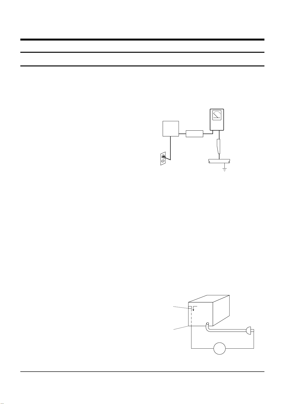
(3) Leakage Current Hot Check-With the instrument
completely reassembled, plug the AC line cord
directly into a 230V(220V ~ 240V) AC outlet. (Do
not use an isolation transformer during this test.)
Use a leakage current tester or a metering system
that complies with American National Standards
institute (ANSI) C101.1 Leakage Current for
Appliances and Underwriters Laboratories (UL)
1270 (40.7). With the instrument’s AC switch first in
the ON position and then in the OFF position, measure from a known earth ground (metal water pipe,
conduit, etc.) to all exposed metal parts of the
instrument (antennas, handle brackets, metal cabinets, screwheads, metallic overlays, control shafts,
etc.), especially any exposed metal parts that offer
an electrical return path to the chassis.
Any current measured must not exceed 0.5mA.
Reverse the instrument power cord plug in the outlet and repeat the test. See Fig. 1-1.
Any measurements not within the limits specified
herein indicate a potential shock hazard that must
be eliminated before returning the instrument to
the customer.
Fig. 1-1 AC Leakage Test
(4) Insulation Resistance Test Cold Check-(1) Unplug
the power supply cord and connect a jumper wire
between the two prongs of the plug. (2) Turn on the
power switch of the instrument. (3) Measure the
resistance with an ohmmeter between the
jumpered AC plug and all exposed metallic cabinet
parts on the instrument, such as screwheads,
antenna, control shafts, handle brackets, etc. When
an exposed metallic part has a return path to the
chassis, the reading should be between 1 and 5.2
megohm. When there is no return path to the chassis, the reading must be infinite. If the reading is
not within the limits specified, there is the possibility of a shock hazard, and the instrument must be
repaired and rechecked before it is returned to the
customer. See Fig. 1-2.
Fig. 1-2 Insulation Resistance Test
DEVICE
UNDER
TEST
2-WIRE CORD
ALSO TEST WITH
PLUG REVERSED
(USING AC ADAPTER
PLUG AS REQUIRED)
TEST ALL
EXPOSED METER
SURFACES
LEAKAGE
CURRENT
TESTER
(READING SHOULD
NOT BE ABOVE
0.5mA)
EARTH
GROUND
Antenna
Terminal
Exposed
Metal Part
ohm
ohmmeter
Page 5

Precautions
1-2
2) Read and comply with all caution and safety related notes on or inside the cabinet, or on the chassis.
3) Design Alteration Warning-Do not alter or add to
the mechanical or electrical design of this instrument. Design alterations and additions, including
but not limited to, circuit modifications and the
addition of items such as auxiliary audio output
connections, might alter the safety characteristics of
this instrument and create a hazard to the user. Any
design alterations or additions will make you, the
servicer, responsible for personal injury or property
damage resulting therefrom.
4) Observe original lead dress. Take extra care to
assure correct lead dress in the following areas:
(1) near sharp edges, (2) near thermally hot parts (be
sure that leads and components do not touch thermally hot parts), (3) the AC supply, (4) high voltage,
and (5) antenna wiring. Always inspect in all areas
for pinched, out-of-place, or frayed wiring, Do not
change spacing between a component and the
printed-circuit board. Check the AC power cord for
damage.
5) Components, parts, and/or wiring that appear to
have overheated or that are otherwise damaged
should be replaced with components, parts and/ or
wiring that meet original specifications.
Additionally, determine the cause of overheating
and/or damage and, if necessary, take corrective
action to remove any potential safety hazard.
6) Product Safety Notice-Some electrical and mechanical parts have special safety-related characteristics
which are often not evident from visual inspection,
nor can the protection they give necessarily be
obtained by replacing them with components rated
for higher voltage, wattage, etc. Parts that have special safety characteristics are identified by shading,
an ( )or a ( )on schematics and parts lists. Use
of a substitute replacement that does not have the
same safety characteristics as the recommended
replacement part might create shock, fire and/or
other hazards. Product safety is under review continuously and new instructions are issued whenever appropriate.
Page 6

Precautions
1-3
CAUTION : Before servicing units covered by this
service manual and its supplements, read and follow
the Safety Precautions section of this manual.
Note : If unforseen circumstances create conflict
between the following servicing precautions and any
of the safety precautions, always follow the safety precautions. Remember: Safety First.
1-2-1 General Servicing Precautions
(1) a. Always unplug the instrument’s AC power cord
from the AC power source before (1) re-moving
or reinstalling any component, circuit board,
module or any other instrument assembly, (2)
disconnecting any instrument electrical plug or
other electrical connection, (3) connecting a test
substitute in parallel with an electrolytic capacitor in the instrument.
b. Do not defeat any plug/socket B+ voltage inter-
locks with which instruments covered by this
service manual might be equipped.
c. Do not apply AC power to this instrument and
/or any of its electrical assemblies unless all
solid-state device heat sinks are correctly installed.
d. Always connect a test instrument’s ground lead
to the instrument chassis ground before connecting the test instrument positive lead. Always
remove the test instrument ground lead last.
Note : Refer to the Safety Precautions section ground
lead last.
(2) The service precautions are indicated or printed on
the cabinet, chassis or components. When servicing, follow the printed or indicated service precautions and service materials.
(3) The components used in the unit have a specified
flame resistance and dielectric strength.
When replacing components, use components
which have the same ratings. Components identified by shading, by( ) or by ( ) in the circuit diagram are important for safety or for the characteristics of the unit. Always replace them with the exact
replacement components.
(4) An insulation tube or tape is sometimes used and
some components are raised above the printed
wiring board for safety. The internal wiring is
sometimes clamped to prevent contact with heating components. Install such elements as they
were.
(5) After servicing, always check that the removed
screws, components, and wiring have been installed correctly and that the portion around the
serviced part has not been damaged and so on.
Further, check the insulation between the blades of
the attachment plug and accessible conductive
parts.
1-2-2 Insulation Checking Procedure
Disconnect the attachment plug from the AC outlet
and turn the power ON. Connect the insulation resistance meter (500V) to the blades of the attachment
plug. The insulation resistance between each blade of
the attachment plug and accessible conductive
parts(see note) should be more than 1 Megohm.
Note : Accessible conductive parts include metal panels, input terminals, earphone jacks, etc.
1-2 Servicing Precautions
Page 7

Precautions
1-4
Electrostatically Sensitive Devices (ESD)
Some semiconductor (solid state) devices can be damaged easily by static electricity.
Such components commonly are called Electrostatically Sensitive Devices(ESD). Examples of typical ESD
devices are integrated circuits and some field-effect
transistors and semiconductor chip components. The
following techniques should be used to help reduce
the incidence of component damage caused by static
electricity.
(1) Immediately before handling any semiconductor
component or semiconductor-equipped assembly,
drain off any electrostatic charge on your body by
touching a known earth ground. Alternatively,
obtain and wear a commercially available discharging wrist strap device, which should be
removed for potential shock reasons prior to applying power to the unit under test.
(2) After removing an electrical assembly equipped
with ESD devices, place the assembly on a conductive surface such as aluminum foil, to prevent electrostatic charge buildup or exposure of the assembly.
(3) Use only a grounded-tip soldering iron to solder or
unsolder ESD devices.
(4) Use only an anti-static solder removal devices.
Some solder removal devices not classified as
“anti-static” can generate electrical charges sufficient to damage ESD devices.
(5) Do not use freon-propelled chemicals. These can
generate electrical charges sufficient to damage
ESD devices.
(6) Do not remove a replacement ESD device from its
protective package until immediately before your
are ready to install it.(Most replacement ESD
devices are packaged with leads electrically shorted together by conductive foam, aluminum foil or
comparable conductive materials).
(7) Immediately before removing the protective ma-
terials from the leads of a replacement ESD device,
touch the protective material to the chassis or circuit assembly into which the device will be
installed.
CAUTION : Be sure no power is applied to the chassis or circuit, and observe all other safety precautions.
(8) Minimize bodily motions when handling unpack-
aged replacement ESD devices. (Otherwise harmless motion such as the brushing together of your
clothes fabric or the lifting of your foot from a carpeted floor can generate static electricity sufficient
to damage an ESD device).
1-3 ESD Precautions
Page 8
2-1
Power requirements 230V AC,50Hz
Power consumption 35Watts
General
Weight 3.7 Kg
Dimensions 430mm(W) x 272mm(D) x 58mm(H)
Operating temp +5°C to +35°C
Other conditions Keep level when operating. Less than 75% operating humidity
Video Composite Video : 1.0 V p-p at 75ohm load, sync negative
Audio Max. Audio input level : 2Vrms
DV Input IEEE 1394(4p) compatible jack
Input Receivable Channels SECAM L/L’, PAL B/G
Scart Jack
AV1 (Scart TV) Video : Composite, Audio : analogue
AV2 (Scart Ext) Video : Composite, RGB Audio : analogue
Audio
Analogue output jacks X 2
Optical/coaxial digital audio output
Composite Video : Video output jack X 1
Output
Video S-Video output X 1 (Y: 1.0Vp-p, C:0.286Vp-p at 75 ohm load)
Component output X 1 (Y: 1.0Vp-p ,Pb:0.70Vp-p, Pr:0.70Vp-p at 75ohm load)
Scart Jack AV1 (Scart TV) Video : Composite, RGB Audio : analogue
Picture compression format MPEG-II
Audio compression format Dolby digital 2ch/256kbps, MPEG-II
Recording
Recording Quality
XP (about 8.5 Mbps), SP (about 4.5 Mbps), LP (about 2.5 Mbps),
EP (about 1.6 Mbps or about 0.8 Mbps), FR (about 1.2 Mbps to 8Mbps)
Audio frequency characteristics 20 Hz ~ 20 KHz
2. Product Specification
2-1 Product Specification
Page 9

Product Specification
2-2
MEMO
Page 10

3-1
3. Software Update
3-1 Drive Firmware Update
3-1-1 Introduction
Toshiba will often support software update to improve the performance of DVD Recorder&VCR to the latest status.
3-1-2 How to make an update disc
• Recommended Application Programme
- Nero Burning / Easy CD Creator ..etc
• Option
- Name : SSC01M222
- Extension name : “*.REC”
- Multisession : No Multisession
- File name lenght : Max. of 11 = 8 + 3
- Format : Mode 1
- Character set : ISO 9660 or Joliet Format
- CD Close & Disc at once
- Label : RAMBO
N O T E
It is very important : please read the below notice before updating your unit.
The following events may interrupt the update process and MAY RESULT IN PERMANENT DAMAGE TO THE UNIT WHILE UPDATING
! The power cord unplugged.
@ Power Outage.
# Dirt or Scratches on the disc.
$ Opening a disc tray during processing.
WARNING
Page 11
3-2
Software Update
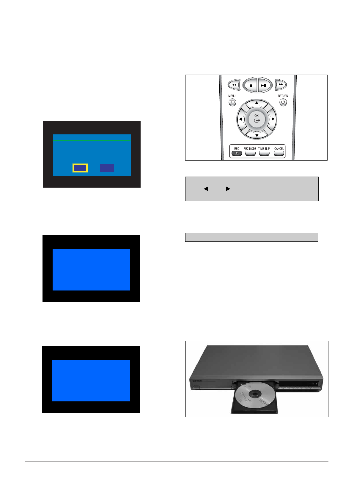
Fig. 3-1
* If you don’t see the message above, try another disc. Generally, this is caused by disc quality and by disc creating problem.
4) Press the OK button on the remote control (Fig. 3-1).
Fig.3-3
5) It takes about 1~2 minutes to complete the update.
The message below will be displayed in the screen after update is completed and the tray will open automatically.
Fig. 3-4
6) After removing the update disc, turn off the unit with power button.
And turn on the unit with power button and then the tray will close.
The drive firmware is now completed.
After checking old and new version, select “Yes” or “No”
with “ ” or “ ” on the remote controller.
* The Version is indicated by “XX.X modelname”
You will see “LOAD” on FLT Display.
Fig. 3-5
1) Press OPEN/CLOSE to open the disc tray.
2) Insert the update CD-R disc with the software update, label
facing up.
3) Press OPEN/CLOSE to close the disc tray.
* It takes about 1~2 minites before the message below appears.
Fig. 3-2 Remote Controller
3-1-3 How to update software
Do you want to update drive-firmware?
Version : YYMMDD.xx.R250 -> YYMMDD.xx.R250
Drive Update
Yes
No
Drive Update
Now, processing...
Please, do not turn off the power.
Drive Update
Drive Firmware is successfully
updated.
Page 12

Software Update
3-3
3-2 Flash Update
3-2-1 Introduction
Toshiba will often support software update to improve the performance of DVD Recorder&VCR to the latest status.
3-2-2 How to make an update disc
• Recommended Application Program
- Nero Burning / Easy CD Creator ..etc
• Option
- Only single session
- CD close & disc at once
- ISO 9660 or joliet format
- Extension name : “*.RUF”
• In order to increase dise playability, add a dummy file (over 100MB) together with the latest program.
(The dummy file can be used any kind of file except MP3, AVI, MPEG, MPG, divx, LPCM, AAC, Ogg file which can be played in the unit
and we recommend to use a file with extension name as “*.dmy”, which can be changed from original one.)
N O T E
It is very important : please read the below notice before updating your unit.
The following events may interrupt the update process and MAY RESULT IN PERMANENT DAMAGE TO THE UNIT WHILE UPDATING
! The power cord unplugged.
@ Power Outage.
# Dirt or Scratches on the disc.
$ Opening a disc tray during processing.
WARNING
Page 13
3-4
Software Update
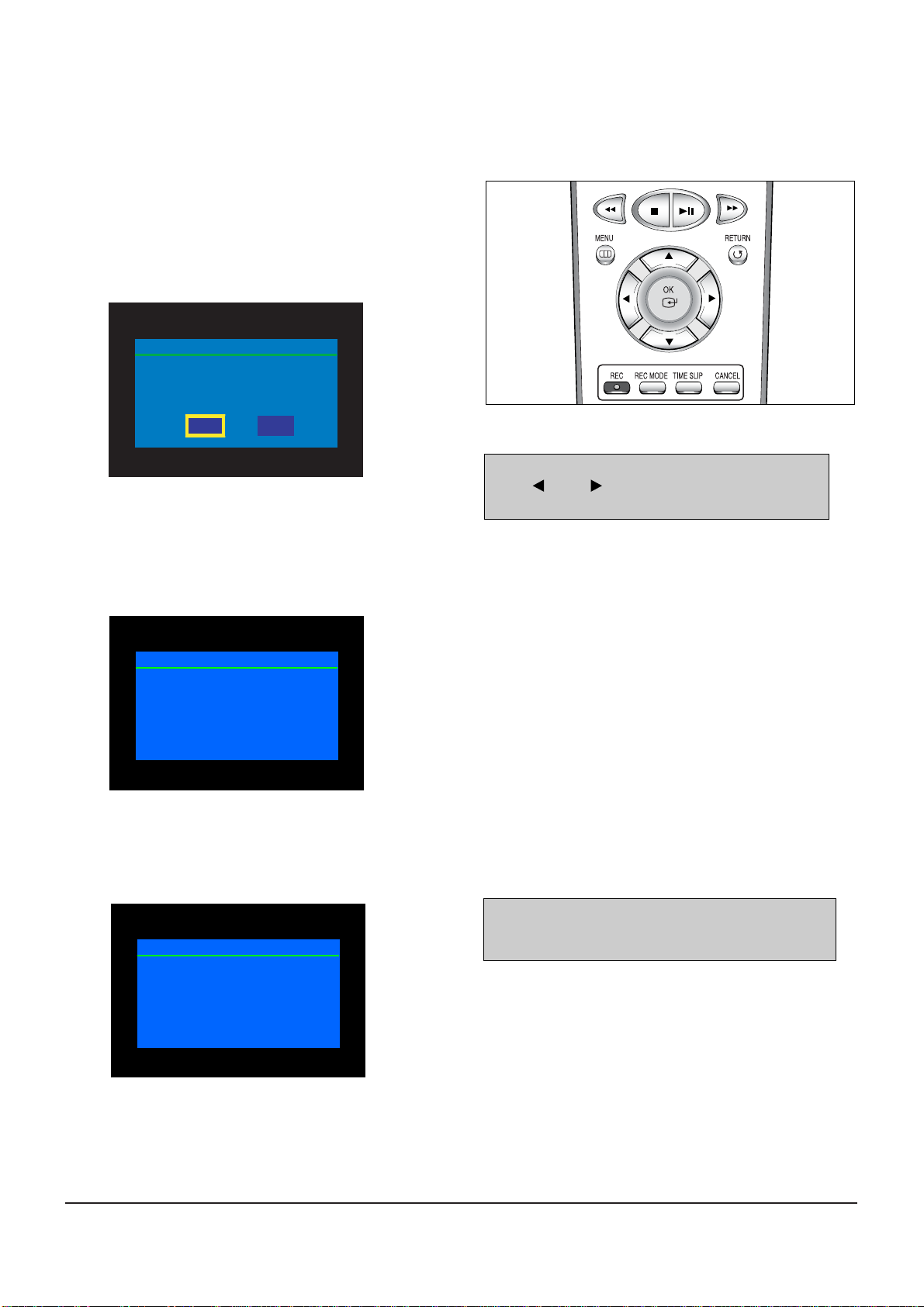
Fig. 3-6
* If you don’t see the message above, try another disc.
Generally, this is caused by disc quality and by disc creating problem.
4) Press the OK button on the remote control (Fig. 3-6).
Fig. 3-8
5) It takes about 5 minutes to complete the update.
The message below will be displayed in the screen after update is completed and the tray will open automatically.
Fig. 3-9
6) After removing the update disc, turn off the unit with power button.
And turn on the unit with power button and then the tray will close.
The Flash update is now completed.
After checking old and new version, select “Yes” or “No”
with “ ” or “ ” on the remote controller.
* The Version is indicated by “YYMMDD.xx modelname”
1) Press OPEN/CLOSE to open the disc tray.
2) Insert the update CD-R disc with the software update, label
facing up.
3) Press OPEN/CLOSE to close the disc tray.
Fig. 3-7 Remote Controller
3-2-3 How to update software
Do you want to update flash memory?
Version : YYMMDD.xx.D-R250 -> YYMMDD.xx.D-R250
Flash Update
Yes
No
Flash Update
Now, processing...
Please, do not turn off the power.
* If the message to the left isn’t displayed after 10minutes
and the unit is no longer functioning properly, contact a
TOSHIBA authorized service center.
Flash Update
Flash memory is successfully
updated.
Page 14
4-1
4. Disassembly and Reassembly
4-1 Cabinet and PCB
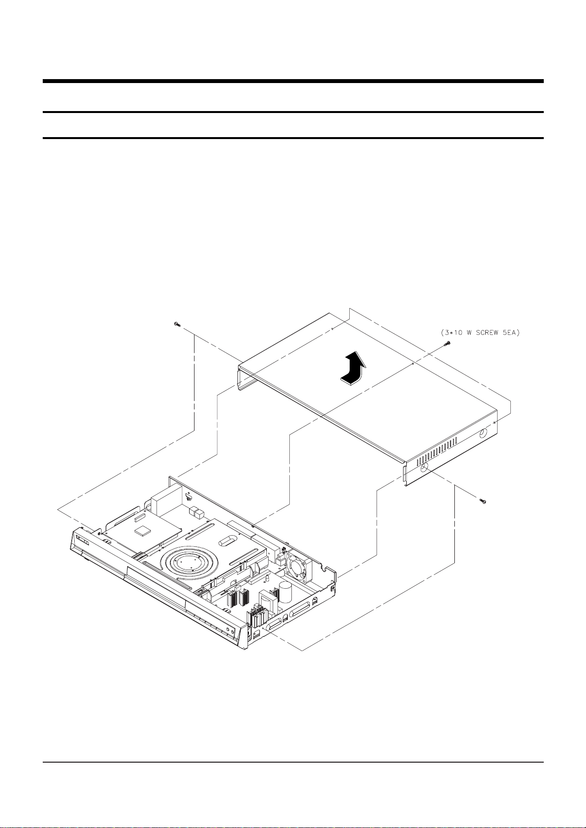
4-1-1 Top Cabinet Removal
1) Remove 5 Screws Œ.
2) Lift up the Top Cabinet in direction of arrow.
Fig. 4-1 Top Cabinet Removal
Note : Reassembly in reverse order.
Π5 SCREWS
Page 15
4-2
Disassembly and Reaasembly
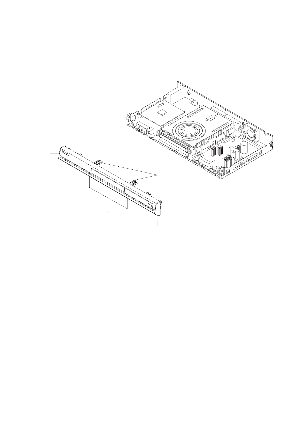
Fig. 4-2 Ass’y Front-Cabinet Removal
4-1-2 Ass’y Front-Cabinet Removal
1) Release 6 Hooks Œ, ´, ˇ, ¨ and Ass’y Front-Cabinet ˆ.
Π1 HOOK
¨ 2 HOOKS
ˇ 2 HOOKS
´ 1 HOOK
ˆ ASS'Y FRONT-CABINET
Page 16
Disassembly and Reaasembly
4-3
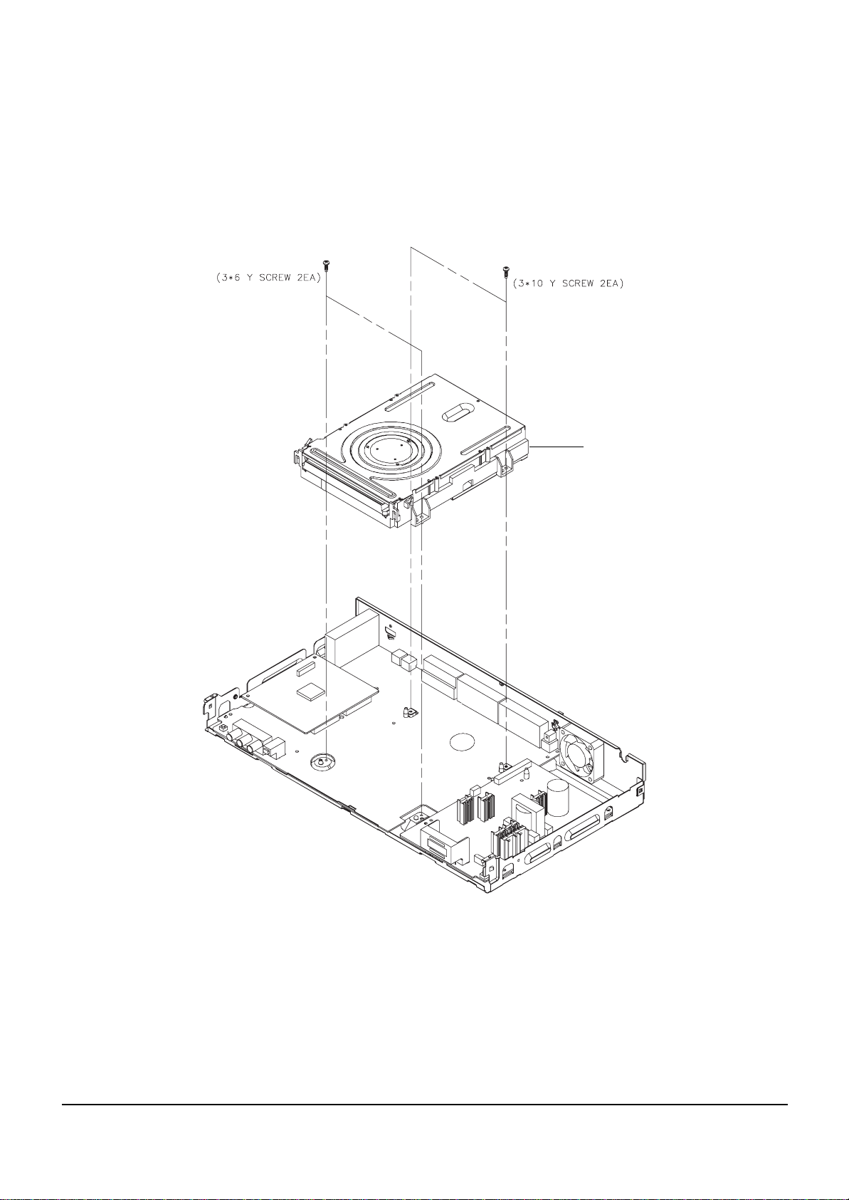
4-1-3 Ass’y Deck Removal
1) Remove 4 Screws Œ, ´ from the Ass’y Deck and lift it up.
Fig. 4-3 Ass’y Deck Removal
Π2 SCREWS
´ 2 SCREWS
ASS'Y-DECK
Page 17
4-4
Disassembly and Reaasembly
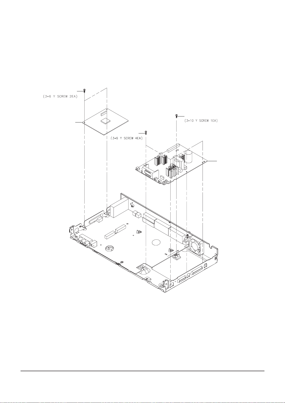
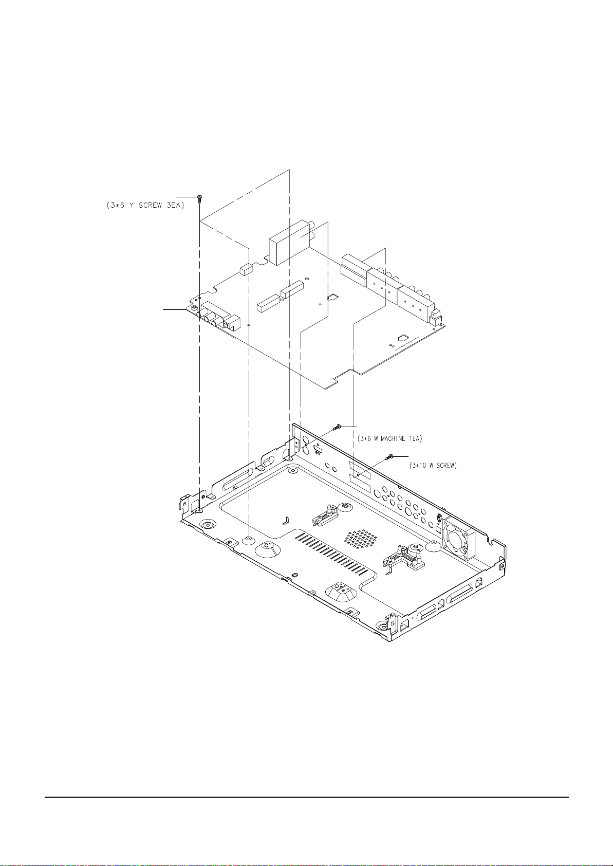
Fig. 4-4 Main PCB and S.M.P.S. PCB Removal
4-1-4 Main PCB and S.M.P.S. PCB Removal
1) Remove 2 Screws Œ, from the Main PCB ´ and lift it up.
2) Remove 5 Screws ˇ ,¨ from the S.M.P.S. PCB ˆ and lift it up.
Π2 SCREWS
´ MAIN PCB
ˇ 4 SCREWS
¨ 1 SCREW
ˆ SMPS PCB
Page 18
Disassembly and Reaasembly
4-5
4-1-5 Jack PCB Removal
1) Remove 5 Screws Œ, ´, ˇ from the Jack PCB ¨ and lift it up.
Fig. 4-5 Jack PCB Removal
Π3 SCREWS
JACK PCB
¨
´ 1 SCREW
ˇ
1 SCREW
Page 19
4-6
Disassembly and Reaasembly
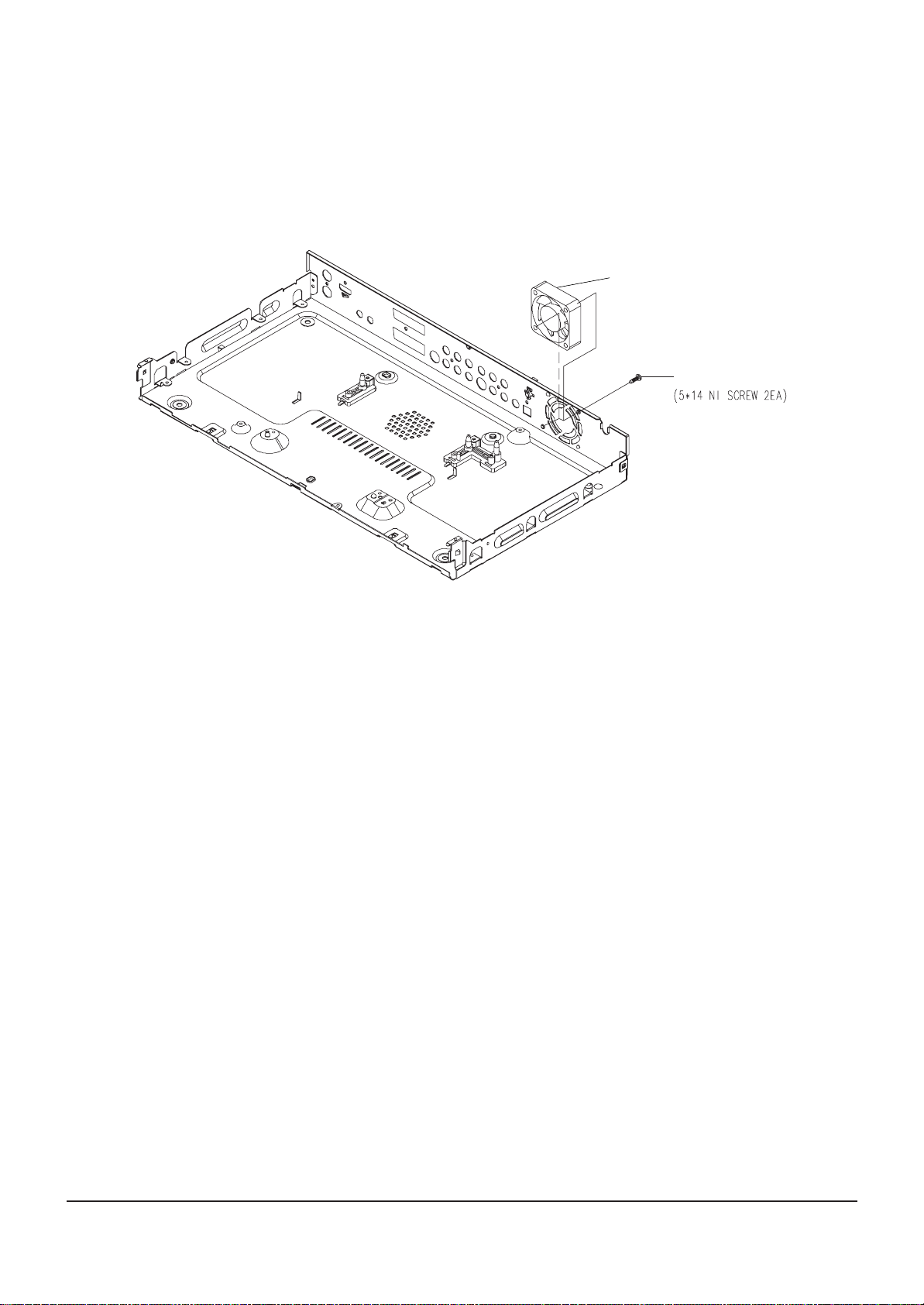
4-1-6 DC FAN Removal
1) Remove 2 Screws Œ, from the DC Fan ´ and lift it up.
Fig. 4-6 DC FAN Removal
´ DC FAN
Π2 SCREWS
Page 20
Disassembly and Reaasembly
4-7
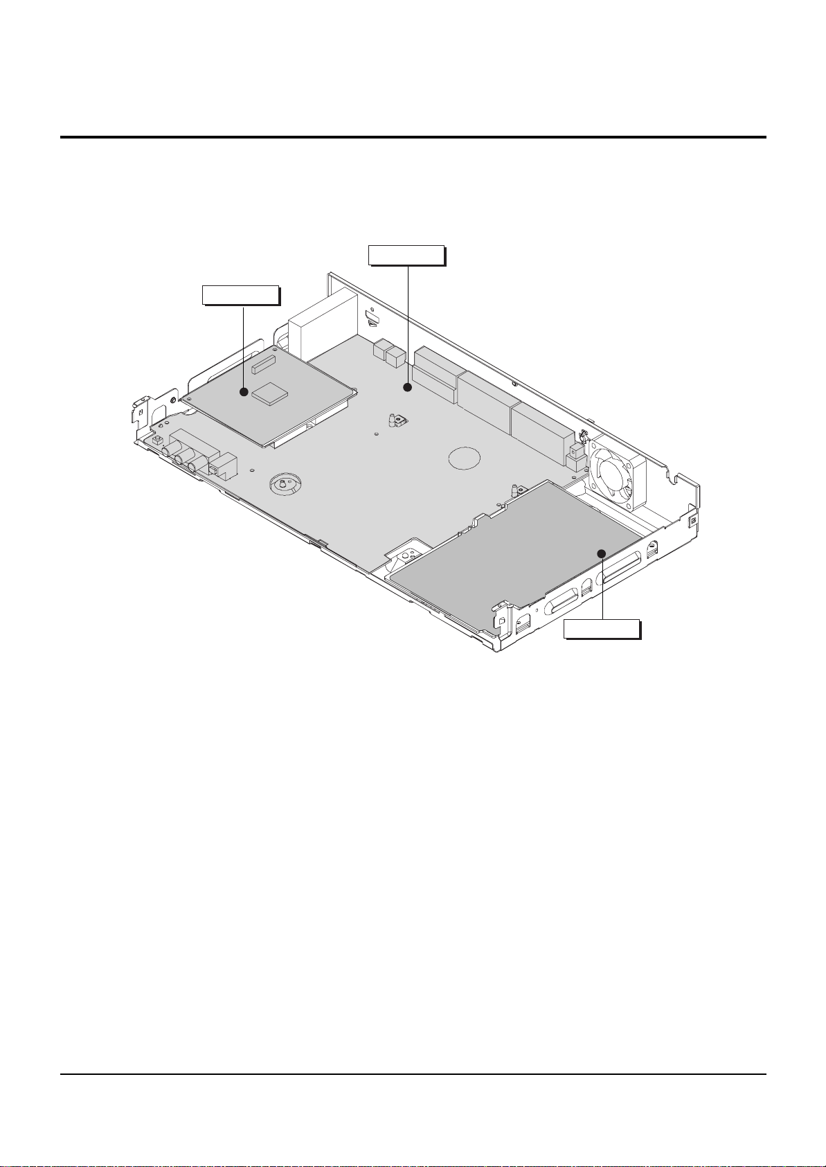
4-2 PCB Location
Fig. 4-7 PCB Location
JACK PCB
MAIN PCB
S.M.P.S. PCB
Page 21

4-8
Disassembly and Reaasembly
MEMO
Page 22
5-1
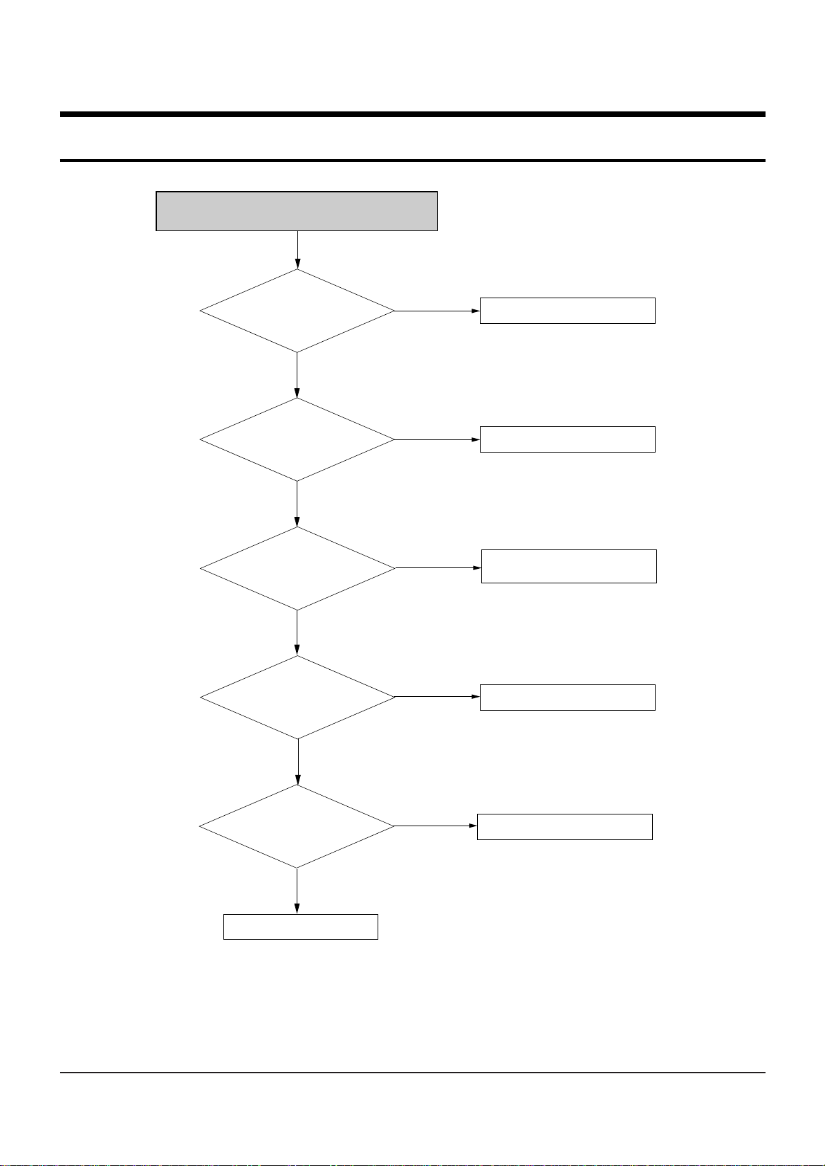
5. Troubleshooting
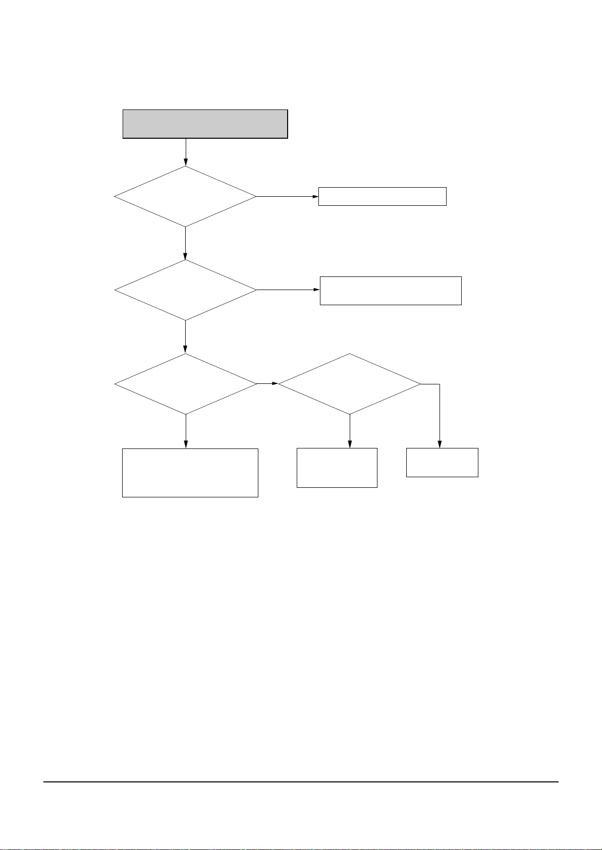
NO Power Detected
(Stand by LED OFF)
PAFT1 is normal?
Yes
Pin 6 of IC701 is normal?
No
PVDLL1, PSDZ1
PFZZ1, PVZL1
SHOR and OPEN
re normal?
a
Yes
voltage at
Is there
Collector of
PPQQX1
No
Yes
No
No
Change fuse
Change DT701 LED Module
Change short circuited or
opened parts
Check 2st voltage
Yes
Operation of PQQX1 is
Normal?
Yes
Check feed back PQIZ1
No
Replace PQQX1
Page 23
Troubleshooting
5-2
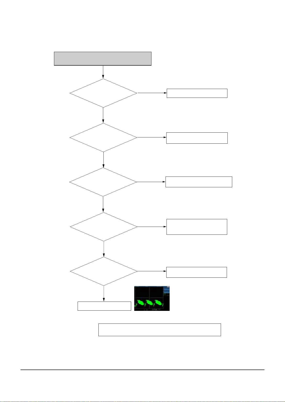
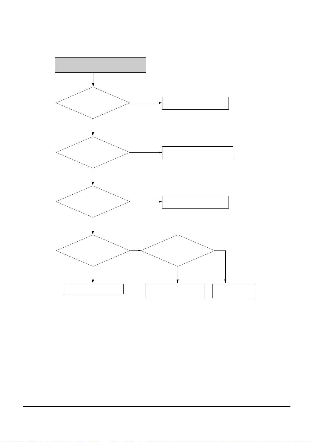
CVBS(Video) output error
Pin 12 in CN3 of jack PCB or
CN2 of Main PCB has
normal level?
Yes
Analog signals are
inputed normally
VIC1(pin4)
Yes
Power is
normal(5V) at VIC(pin1,28)?
Yes
Pin3 in VIC1 is
in high state?
No
No
No
No
Check the DIC1 on MAIN B/D
Check the connection between
pin 12 in CN3 of JACK PCB and VIC1
Check the connection between
VIC1(pin1,28) and power line(FD6,VL6).
Check the connection between
VIC1(pin3) and FIC1(39pin).
check VIC1 peripheral circuit
Yes
Video signal of
About P-P1V appears at
Output Jack?
Yes
Check the RCA cable
# IF Recorder is under PSO(progressive scan output) MODE, it does not
No
CVBS(Color-bar)
output the CVBS& S-Video, RGB signal.
Check the connection between
VIC1 and output Jack
Page 24
Troubleshooting
5-3
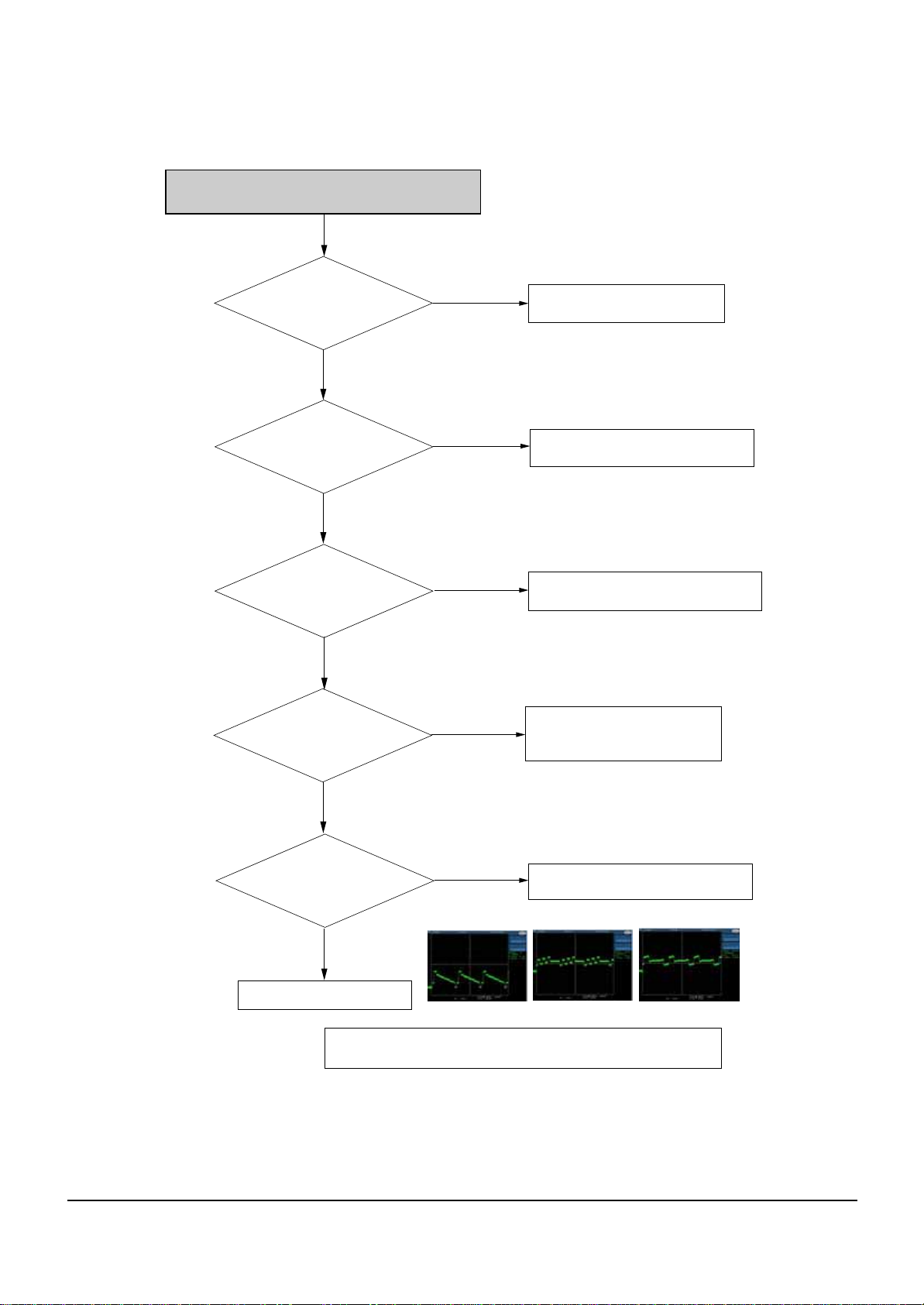
Component (Y, Cb, Cr) output error
Pin 2,4,6 Pin in CN3 of
Jack PCB or CN2 of Main PCB
has normal level?
Yes
Analong signals are
inputted normally
VIC1 (pin 10,12,14)
Yes
Power is normal (5V) at
VIC1(Pin1,28)?
Yes
Pin3 in VIC1 is
in high state?
No
No
No
No
Check the DIC1 on Main PCB
Check the connection between pin 2,4,6
in CN3 of JACK PCB and VIC1
Check the connection between
VIC1(pin1,28) and Power line (pin 4 of PCN1)
Check the connection between
VIC1(pin3) and FIC1 (pin 39).
Check VIC1 peripheral circuit.
Yes
Video signal of
About P-P1V appears at
Output Jack?
Yes
Check the RCA cable
# IF Recorder is under PSO(progressive scan output) MODE, or it does not
No
Y(Color-bar)
output the CVBS& S-Video signal.
Check the connection between VIC1
Pb(Color-bar) Pr(Color-bar)
and output Jack
Page 25
Troubleshooting
5-4
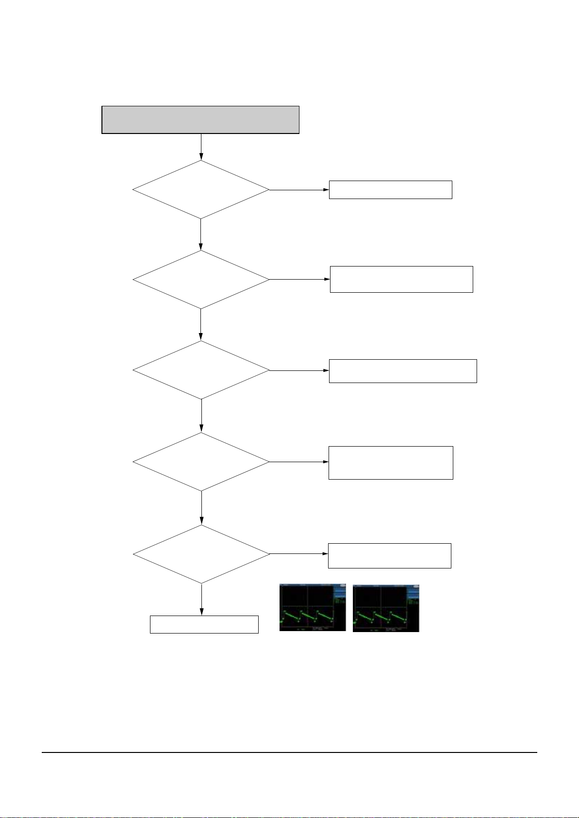
S-Video output error
Pin 10 and pin 8 in CN3 of
Jack PCB or CN2 of Main
PCB has normal level?
Yes
Analog signals are
inputted normally
VIC1(pin4)
Yes
Power is normal (5V)
at VIC1(pin1,28)?
Yes
Pin13 in VIC1 is
In high state?
Yes
No
No
No
No
Check the DIC1 on Main PCB
Check the connection between pin 10 and
pin 8 in CN3 of Jack PCB and VIC1
Check the connection between
VIC1(pin 1,28) and power line(pin 4 of PCN1).
Check the connection between
VIC1(pin13)and FIC1(pin 44)
Check VIC1 peripheral circuit.
Video signals of
about P-P1V appears at
output Jack?
Yes
Check the S-Video cable
No
Y(Color-bar)
Check the connection between
VIC1 and output Jack
C(Color-bar)
Page 26
Troubleshooting
5-5
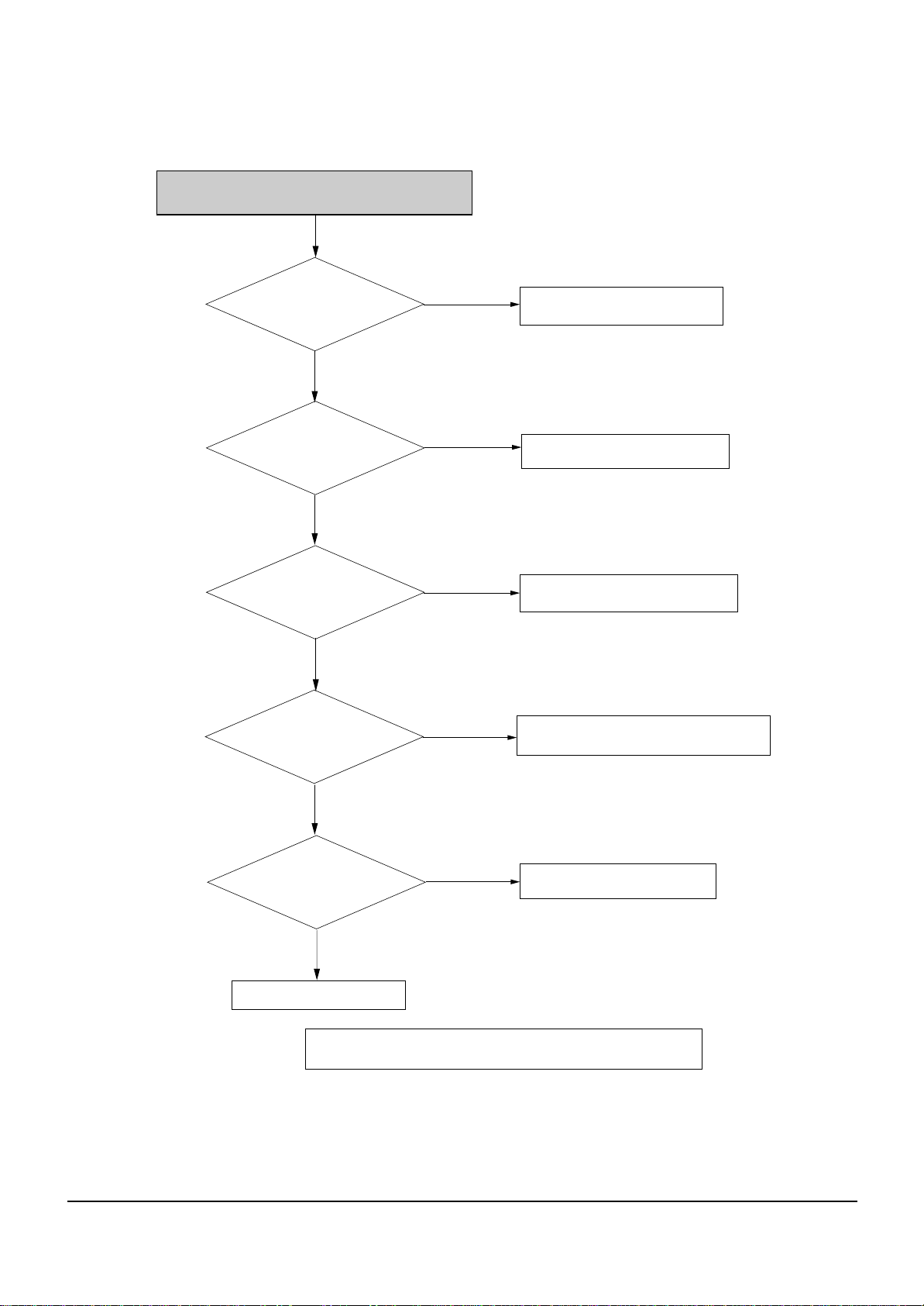
AV1 (RGB) Output Error
Pin 2,4, 6 pin in CN3
ofJack PCB or CN2 of Main PCB
has normal level?
Yes
Analog signals are
inputted normally
VIC1(pin 10, 12, 14)
Yes
Power is
normal at VIC1-1,28?
Yes
RGB control signal
level is 4V at pin 16 of
SCJ1 (AV1Jack)?
No
No
No
No
Check Main PCB
Check the connection between pin 2,4,
6 in CN3 of Jack PCB and VIC1.
Check the connection between
pin 1, 28 of VIC1 and power
Check the connection between
pin 13 of SIC1 and AV1 Jack
Yes
RGB Video signal
appears at pin 7, 11, 15 of
AV1 output Jack?
Yes
Check the RCA cable
# IF Recorder is under Component mode (in OSD setup menu),
No
it does not output RGB out put.
Check the connection between
VIC1 and output Jack.
Page 27
Troubleshooting
5-6
AV1, AV2 (CVBS) output error
Pin 12 of CN3 in
jack PCB has normal
level?
Yes
Analog signal are
Inputted normally
pin 5 of SIC1
Yes
Analog signal are
out normally
SIC1-29(AV2),30(AV1)
Yes
Check the connection between
SIC1 and SCART Jack
-AV1 ; pin 30 of SIC1 and pin 19 of AV1
-AV2 : pin 29 of SIC1 and pin 40 of AV2
No
No
No
supply to pin 2, 4, 6 of SIC1?
Check the I2C line
(between SIC1-32, 33
and FIC1-27, 28)
Check Main PCB
Check the connection between
pin 12 of CN3 in
Check the power
Jack PCB and SIC1
No
Yes
Check the SMPS
(AL5.8V)
Page 28
Troubleshooting
5-7
AV2 (RGB) Input Error
Video signal of
about 0.7V appears at input jack?
(pin 28, 32, 36 of AV2)
Yes
RGB control signal
level is 4V at pin 27 of SCJ1
(AV1Jack)?
Yes
Check the power
supply to pin 2, 4, 6 of SIC1
Yes
CN3-19,21,23 of
Jack PCB or CN2 of Main PCB
has normal level?
No
No
No
No
Check the Scart cable.
Check Video out of TV is set RGB mode.
Check the SMPS(AL5.8V)
Check the I2C line
(between SIC-32, 33
and FIC1-27)
No
Yes
Check Main PCB
Yes
Check the connection between
CN3-19, 21, 23 and Scart Jack.
Check the pins of FIC1
is not short
Page 29
Troubleshooting
5-8
AV3 CVBS Video Input Error
Pin 15 in IC201
has normal level?
Yes
Pin 3 in IC201(Input MUX)
has normal level?
Yes
CN3-13 of
jack PCB or CN2 of Main PCB
has normal level?
No
No
No
Check the connection between CN3-13
Check the connection between
pin 15 in IC201 and AV3 pin-jack
Check the connection between
IC201-9, 10, 11 and FIC1
Control signal of pin 9, 10, 11 in
IC201 is as below.
AV3 Input : L/H/L
AV2 Input : H/H/H
AV1 Input : L/H/H
PROG Input : L/L/L
of jack PCB and pin 3 in IC201
Yes
Change Main PCB
Page 30
Troubleshooting
5-9
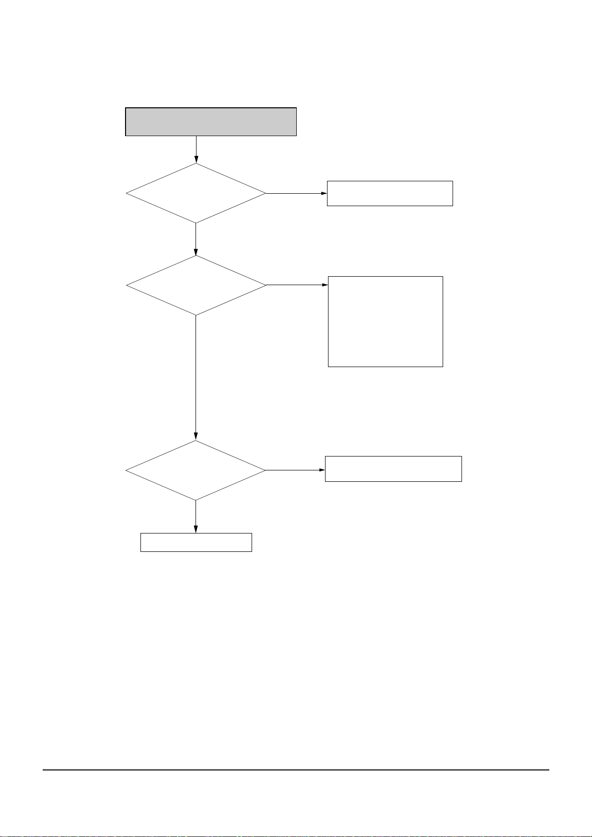
There's no Digital Audio Out
Check Current Digital Audio
Setting is PCM.
Yes
Check Digital Audio data
at DR1(Main PCB)
Yes
ChecK Digital Audio data
at pin 10 of CN4
(Main PCB)
Yes
Check 5V AVJ5
No
No
No
No
Check the A/V Receiver
can Decode Current
Bit-Steam
Yes
Replace Main PCB
Replace Main PCB
Replace AVJ5
No
Set the Bitstream
Yes
Check the Cable
AUDIO
DATA
Page 31

Troubleshooting
5-10
AV3 Audio Input is not Recording
Check the select signal pin 9,10
of AIC51(Jack PCB)
Yes
Check all the 12Vcc
pin 16 of AIC51(Jack PCB).
Yes
Check the 3.3V pin14
and 5V pin5 of AIC9
(Main PCB)
Yes
Check Digital clock and data
pin 10, 11, 12, 15 of
AIC9(Main PCB)
Yes
No
No
No
No
Digital clock(10)
Check pin 30, 36 of the Front Mrcom
FIC1 (Jack PCB)
Check SMPS
Replace Main PCB
Replace Main PCB
Digital clock(11)
Digital clock(12) Digital clock(15)
Check the passive parts
around jack pin.
Page 32

Troubleshooting
5-11
There is no Audio Output
Check he audio signal
AR413 and AR473
(Jack PCB)
No
Check all the 5V pin 8
of AIC1
(Main PCB)
Yes
Check the audio signal pin 7
pin8 of AIC1
(Main PCB)
Yes
Check digital clock and
data pin 1, 2, 3, 16 of AIC1
(Main PCB)
Yes
Yes
No
No
No
AUDIO
Check the passive parts around
Audio Jack pin.
Check SMPS
Replace Main PCB
Replace Main PCB
DATA
Check connection between Main connector (CN1, CN2)
and Jack connector (CN3, CN4)
Page 33

Troubleshooting
5-12
Disc Ioading error
Are Main and deck
power OK?
(5V, 12V)
Yes
Is the pin 40
FFC cable(between Main & Deck)
inserted correctly?
Yes
Is the wavefrom
of DIC3 pin 26 normal?
(Main PCB)
Yes
Change the Deck
No
No
No
DIC3-Pin26
the power
Check
Reinsert FFC cable correctly
Change the Main PCB
Page 34

Troubleshooting
5-13
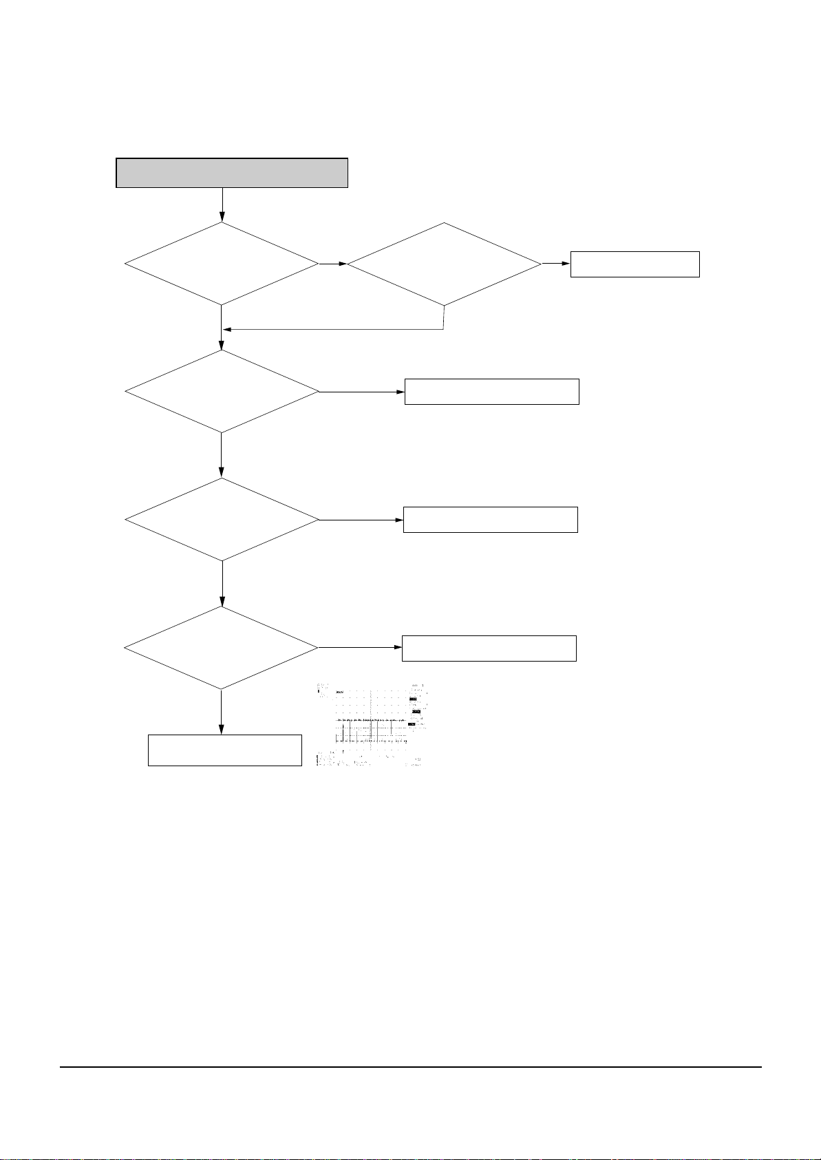
Tuner Video Out Abnormal
Tuner input line signal
is OK? (Jack PCB)
Yes
Supplied power for
tuner is OK?
pin 1, 3 : 5V
pin 16 : 33V
Yes
I2C signal pin 11, 12 of
tuner is OK?
Yes
Video output signal
of Tuner is OK?
(Jack PCB)
No
Tuner Video
No
No
No
Tuner line connect TV directly
Check SMPS (AL5.8V and 33V)
Check between pin 11, 12 of tuner
and FIC1.
Replace TM (tuner) block.
Yes
Refer to AV3 Video line error
Page 35

Troubleshooting
5-14
Tuner Audio Out Abnormal
Tuner line signal is OK?
Yes
Supplied power
for TIC1 (5V,8V)is OK?
(Jack PCB)
Yes
5.5MHz signal from pin15
of tuner is OK?
Yes
Does TY1 make
18.432Mhz signal?
(Jack PCB)
No
No
No
Tuner Audio
No
Tuner line connect TV directly.
Check its power line or around elements
Check the SIF signal or tuner
Check TY1 or around elements
Yes
If Audio R/L signal (pin 30,31 of TIC1)
is normal, refer to AV3 Audio Line in error
Page 36

Troubleshooting
5-15
Remocon no work
KRMC1(pin 1) signal
is OK? (SMPS PCB)
FIC1(pin 58) signal
is OK? (Jack PCB)
Change IC601 or
Yes
Yes
around elements
No
No
Check the power (pin2) line
of KRMC1 is 5V.
Check between FIC1(pin 58) and KRMC1(pin 1).
Page 37

Troubleshooting
5-16
MEMO
Page 38

6-1
6. Exploded View and Parts List
6-1 Cabinet Assembly - - - - - - - - - - - - - - - - - - - - - - - - - - - - - - - - - - - - - - - - -
Page
6-2
Page 39

Exploded Views and Parts List
6-2
6-1 Cabinet Assembly
A001
W275
W009
W275
W009
W275
W272
P001
S.N.A
P025
P030
W271
H001
S.N.A.: Service Not Available
C001
C011
C002
C022
W275
W268
P022
P003
Page 40

Exploded Views and Parts List
6-3
Loc. No Reference No. TSB Parts No. Description ; Specification Remark
A001 AK59-00035B BZ634006 REMOCON-ASSY;D-R250-S-TB,TSB,187.5*54,-,
C001 AK97-01351A BY734171 ASSY-PANEL FRONT;HIPS 94HB,D-R250,05-TSB
C002 AK64-01353A BY734127 DOOR-TRAY;D-R250,ABS 94HB,T2.5,-,W120,L2
C011 AC61-00267A BY734102 SPRING ETC-DOOR TRAY;DVD-V5000K,SUS304,C015 AK64-01069B BY734121 CABINET-TOP;DVD-R120,PCM,T0.6,W430,L45,C022 AK64-01352A BY734126 DOOR-FRONT;D-R250,ABS 94HB,T2.5,-,W50,L3
H001 AK97-01211A BY634963 ASSY-ASSY LOADER DRIVE;-,SV-R250,ASSY LO
P001 AK92-00743A BY630518 ASSY PCB-MAIN;D-R250-S-TB,MAIN D-R250-SB
AK92-00744A BY630519 ASSY PCB-MAIN;D-R255-S-TG,MAIN D-R255-SG,D-R255-SF
P003 AK92-00725A BY630517 ASSY PCB-SMPS;D-R250,P022 AK92-00651H BY630515 ASSY PCB-JACK;D-R250,TB,TG D-R250-SB, D-R255-SG
AK92-00651J BY630516 ASSY PCB-JACK;D-R255,TF D-R255-SF
P025 AC39-12022K BY634126 CBF-POWER CORD;AT,,GP2,HOUING(2P),250V,3 D-R250-SB
AC39-10019A BY634124 CBF-POWER CORD;KKP-419C,H03VVH2-F,VDE/KE D-R255-SG,D-R255-SF
P030 3103-001158 BY634994 FAN-DC;12V,20mA,2000rpm,0.125m^3/mi,7
W009 6003-000276 22797133 SCREW-TAPTITE;BH,+,B,M3,L10,ZPC(YEL),SWC
W268 6003-000254 BY734068 SCREW-TAPTITE;BH,+,S,M3,L6,ZPC(WHT),SM20
W271 6009-001411 BY731644 SCREW-SPECIAL;TH,+,-,M5,L14,NI PLT,SWRCH
W272 6003-001464 BY731645 SCREW-TAPTITE;BH,+,B,M3,L10,ZPC(WHT)
W275 6003-001561 BY731750 SCREW-TAPTITE;BH,+,WT,B,M3,L6,ZPC(YEL),S
AC39-42001R BY644791 CABLE-A/V;PVC,-,-,3P,-,-,- D-R250-SB,D-R255-SG
D-R255-SF
AC39-00017A BY634253 CABLE-ETC-RF(PAL);-,MALE/FEMALE,1200MM,R D-R250-SB,D-R255-SG
AC39-00018A BY634851 CABLE-ETC-RF(SECAM);-,BOTH MALE,1200MM,R D-R255-SF
AK68-00836A BY734207 MANUAL USERS;D-R250/TB,TSB,ENGLISH,MOJO8 D-R250-SB
AK68-00837A BY734208 MANUAL USERS;D-R255/TF,TSB,FRA,MOJO80,-Z D-R255-SF
AK68-00838A BY734209 MANUAL USERS;D-R255/TG,TSB,ENG,DE,ES,ITA D-R255-SG
Page 41

Exploded Views and Parts List
6-4
MEMO
Page 42

P001 AK92-00743A BY630518 ASSY PCB-MAIN;D-R250-S-TB,MAIN D-R250-SB
AK92-00744A BY630519 ASSY PCB-MAIN;D-R255-S-TG,MAIN D-R255-SG,D-R255-SF
AC101 2203-000491 BY130443 C-CER,CHIP;2.2nF,10%,50V,X7R,TP,1608,AC104 2402-001059 BY130556 C-AL,SMD;220UF,20%,6.3V,-,TP,6X6.6X6.6
AC105 2203-005148 BY130480 C-CER,CHIP;100nF,10%,16V,X7R,TP,1608
AC4 2203-005148 BY130480 C-CER,CHIP;100nF,10%,16V,X7R,TP,1608
AC5 2203-005148 BY130480 C-CER,CHIP;100nF,10%,16V,X7R,TP,1608
AC6 2203-005148 BY130480 C-CER,CHIP;100nF,10%,16V,X7R,TP,1608
AC7 2203-005148 BY130480 C-CER,CHIP;100nF,10%,16V,X7R,TP,1608
AC8 2203-005148 BY130480 C-CER,CHIP;100nF,10%,16V,X7R,TP,1608
AC816 2203-000236 BY130439 C-CER,CHIP;0.1NF,5%,50V,C0G,TP,1608
AC818 2203-000236 BY130439 C-CER,CHIP;0.1NF,5%,50V,C0G,TP,1608
AC820 2203-000783 BY130435 C-CER,CHIP;0.33NF,5%,50V,C0G,TP,1608
AC821 2203-001554 BY130450 C-CER,CHIP;1.8nF,10%,50V,X7R,TP,1608
AC822 2402-000176 BY130504 C-AL,SMD;10uF,20%,16V,GP,TP,4.3x4.3x5.4
AC823 2203-000783 BY130435 C-CER,CHIP;0.33NF,5%,50V,C0G,TP,1608
AC824 2203-001554 BY130450 C-CER,CHIP;1.8nF,10%,50V,X7R,TP,1608
AC831 2402-000176 BY130504 C-AL,SMD;10uF,20%,16V,GP,TP,4.3x4.3x5.4
AC891 2203-005148 BY130480 C-CER,CHIP;100nF,10%,16V,X7R,TP,1608
AC892 2203-005148 BY130480 C-CER,CHIP;100nF,10%,16V,X7R,TP,1608
AC908 2203-000491 BY130443 C-CER,CHIP;2.2nF,10%,50V,X7R,TP,1608,AC911 2402-000176 BY130504 C-AL,SMD;10uF,20%,16V,GP,TP,4.3x4.3x5.4
AC912 2203-000491 BY130443 C-CER,CHIP;2.2nF,10%,50V,X7R,TP,1608,AC913 2402-000007 BY130502 C-AL,SMD;22uF,20%,6.3V,GP,TP,4.3x4.3x5.
AC914 2203-000491 BY130443 C-CER,CHIP;2.2nF,10%,50V,X7R,TP,1608,AC915 2402-000176 BY130504 C-AL,SMD;10uF,20%,16V,GP,TP,4.3x4.3x5.4
AC917 2402-000176 BY130504 C-AL,SMD;10uF,20%,16V,GP,TP,4.3x4.3x5.4
AC918 2203-005148 BY130480 C-CER,CHIP;100nF,10%,16V,X7R,TP,1608
AC919 2402-001059 BY130556 C-AL,SMD;220UF,20%,6.3V,-,TP,6X6.6X6.6
AE2 2402-001059 BY130556 C-AL,SMD;220UF,20%,6.3V,-,TP,6X6.6X6.6
AE3 2402-000179 BY130505 C-AL,SMD;47uF,20%,16V,GP,TP,6.6x6.6x5.4
AIC1 1002-001294 BY631221 IC-D/A CONVERTER;PCM1742KE,24BIT,TSSOP,1
AIC3 1203-002178 BY631234 IC-POSI.FIXED REG.;1563,SOP,7P,173MIL,PL
AIC81 1201-000163 BY631232 IC-OP AMP;4560,SOP,8P,173MIL,DUAL,100V/m
AIC82 1201-000163 BY631232 IC-OP AMP;4560,SOP,8P,173MIL,DUAL,100V/m
AIC9 1002-001387 BY631222 IC-A/D CONVERTER;PCM1802,24BIT,SSOP,20P,
AL1 3301-001419 BY330073 BEAD-SMD;-,220,-,500,TP,-,0.3
AL2 3301-001419 BY330073 BEAD-SMD;-,220,-,500,TP,-,0.3
AL3 3301-001419 BY330073 BEAD-SMD;-,220,-,500,TP,-,0.3
AL4 3301-001419 BY330073 BEAD-SMD;-,220,-,500,TP,-,0.3
AR10 2007-000113 BY230328 R-CHIP;33ohm,5%,1/10W,TP,1608
AR11 2007-000113 BY230328 R-CHIP;33ohm,5%,1/10W,TP,1608
AR12 2007-000113 BY230328 R-CHIP;33ohm,5%,1/10W,TP,1608
AR13 2007-000113 BY230328 R-CHIP;33ohm,5%,1/10W,TP,1608
AR14 2007-000113 BY230328 R-CHIP;33ohm,5%,1/10W,TP,1608
AR15 2007-000120 BY230350 R-CHIP;680ohm,5%,1/10W,TP,1608
AR16 2007-000070 BY230274 R-CHIP;0ohm,5%,1/10W,TP,1608
AR2 2007-000090 BY230285 R-CHIP;10Kohm,5%,1/10W,TP,1608
AR20 2007-000029 70795513 R-CHIP;0ohm,5%,1/8W,TP,2012
AR3 2007-000115 BY230348 R-CHIP;82ohm,5%,1/10W,TP,1608
AR4 2007-000113 BY230328 R-CHIP;33ohm,5%,1/10W,TP,1608
AR5 2007-000113 BY230328 R-CHIP;33ohm,5%,1/10W,TP,1608
AR51 2007-000070 BY230274 R-CHIP;0ohm,5%,1/10W,TP,1608
AR52 2007-000070 BY230274 R-CHIP;0ohm,5%,1/10W,TP,1608
AR6 2007-000084 BY230282 R-CHIP;4.7Kohm,5%,1/10W,TP,1608
AR7 2007-000115 BY230348 R-CHIP;82ohm,5%,1/10W,TP,1608
AR8 2007-000113 BY230328 R-CHIP;33ohm,5%,1/10W,TP,1608
AR801 2007-000084 BY230282 R-CHIP;4.7Kohm,5%,1/10W,TP,1608
AR802 2007-000084 BY230282 R-CHIP;4.7Kohm,5%,1/10W,TP,1608
AR803 2007-000084 BY230282 R-CHIP;4.7Kohm,5%,1/10W,TP,1608
AR804 2007-000082 BY230233 R-CHIP;3.3Kohm,5%,1/10W,TP,1608
AR805 2007-000122 BY230294 R-CHIP;1.2Kohm,5%,1/10W,TP,1608
AR806 2007-000084 BY230282 R-CHIP;4.7Kohm,5%,1/10W,TP,1608
7-1
7. Electrical Parts List
Loc. No Reference No. TSB Parts No. Description ; Specification Remark
Page 43

AR807 2007-000122 BY230294 R-CHIP;1.2Kohm,5%,1/10W,TP,1608
AR808 2007-000082 BY230233 R-CHIP;3.3Kohm,5%,1/10W,TP,1608
AR809 2007-000080 BY230343 R-CHIP;2Kohm,5%,1/10W,TP,1608
AR811 2007-000080 BY230343 R-CHIP;2Kohm,5%,1/10W,TP,1608
AR812 2007-000080 BY230343 R-CHIP;2Kohm,5%,1/10W,TP,1608
AR813 2007-000084 BY230282 R-CHIP;4.7Kohm,5%,1/10W,TP,1608
AR814 2007-000084 BY230282 R-CHIP;4.7Kohm,5%,1/10W,TP,1608
AR881 2007-000090 BY230285 R-CHIP;10Kohm,5%,1/10W,TP,1608
AR882 2007-000090 BY230285 R-CHIP;10Kohm,5%,1/10W,TP,1608
AR894 2007-000090 BY230285 R-CHIP;10Kohm,5%,1/10W,TP,1608
AR895 2007-000090 BY230285 R-CHIP;10Kohm,5%,1/10W,TP,1608
AR9 2007-000115 BY230348 R-CHIP;82ohm,5%,1/10W,TP,1608
ATAR1 2011-000475 BY230366 R-NET;33OHM,5%,1/16W,L,CHIP,8P,TP,32
ATAR2 2011-000475 BY230366 R-NET;33OHM,5%,1/16W,L,CHIP,8P,TP,32
ATAR3 2011-000475 BY230366 R-NET;33OHM,5%,1/16W,L,CHIP,8P,TP,32
ATAR4 2011-000475 BY230366 R-NET;33OHM,5%,1/16W,L,CHIP,8P,TP,32
ATCN1 3708-001935 BY634823 CONNECTOR-FPC/FFC/PIC;40P,0.5mm,SMD-S,Sn
C110 2203-005148 BY130480 C-CER,CHIP;100nF,10%,16V,X7R,TP,1608
C111 2203-005148 BY130480 C-CER,CHIP;100nF,10%,16V,X7R,TP,1608
C112 2203-005148 BY130480 C-CER,CHIP;100nF,10%,16V,X7R,TP,1608
C115 2203-005148 BY130480 C-CER,CHIP;100nF,10%,16V,X7R,TP,1608
C117 2203-005148 BY130480 C-CER,CHIP;100nF,10%,16V,X7R,TP,1608
C119 2203-005148 BY130480 C-CER,CHIP;100nF,10%,16V,X7R,TP,1608
C123 2402-001237 BY130509 C-AL,SMD;330uF,##20%,6.3V,-,REEL,6.3X7.
C124 2402-001237 BY130509 C-AL,SMD;330uF,##20%,6.3V,-,REEL,6.3X7.
C125 2203-005148 BY130480 C-CER,CHIP;100nF,10%,16V,X7R,TP,1608
C126 2203-005148 BY130480 C-CER,CHIP;100nF,10%,16V,X7R,TP,1608
C127 2203-005148 BY130480 C-CER,CHIP;100nF,10%,16V,X7R,TP,1608
C128 2203-005148 BY130480 C-CER,CHIP;100nF,10%,16V,X7R,TP,1608
C129 2203-005148 BY130480 C-CER,CHIP;100nF,10%,16V,X7R,TP,1608
C130 2203-005148 BY130480 C-CER,CHIP;100nF,10%,16V,X7R,TP,1608
C140 2203-005148 BY130480 C-CER,CHIP;100nF,10%,16V,X7R,TP,1608
C141 2203-005148 BY130480 C-CER,CHIP;100nF,10%,16V,X7R,TP,1608
C142 2203-005148 BY130480 C-CER,CHIP;100nF,10%,16V,X7R,TP,1608
C143 2203-005148 BY130480 C-CER,CHIP;100nF,10%,16V,X7R,TP,1608
C144 2203-005148 BY130480 C-CER,CHIP;100nF,10%,16V,X7R,TP,1608
C145 2203-005148 BY130480 C-CER,CHIP;100nF,10%,16V,X7R,TP,1608
C146 2203-005148 BY130480 C-CER,CHIP;100nF,10%,16V,X7R,TP,1608
C147 2203-005148 BY130480 C-CER,CHIP;100nF,10%,16V,X7R,TP,1608
C150 2203-005148 BY130480 C-CER,CHIP;100nF,10%,16V,X7R,TP,1608
C166 2203-000440 BY130462 C-CER,CHIP;1nF,10%,50V,X7R,TP,1608,C167 2203-005148 BY130480 C-CER,CHIP;100nF,10%,16V,X7R,TP,1608
C168 2203-005148 BY130480 C-CER,CHIP;100nF,10%,16V,X7R,TP,1608
C169 2203-005148 BY130480 C-CER,CHIP;100nF,10%,16V,X7R,TP,1608
C171 2203-005148 BY130480 C-CER,CHIP;100nF,10%,16V,X7R,TP,1608
C173 2402-000176 BY130504 C-AL,SMD;10uF,20%,16V,GP,TP,4.3x4.3x5.4
C174 2402-001059 BY130556 C-AL,SMD;220UF,20%,6.3V,-,TP,6X6.6X6.6
C177 2203-005148 BY130480 C-CER,CHIP;100nF,10%,16V,X7R,TP,1608
C178 2203-000440 BY130462 C-CER,CHIP;1nF,10%,50V,X7R,TP,1608,C179 2203-005148 BY130480 C-CER,CHIP;100nF,10%,16V,X7R,TP,1608
C183 2203-005148 BY130480 C-CER,CHIP;100nF,10%,16V,X7R,TP,1608
C184 2203-005148 BY130480 C-CER,CHIP;100nF,10%,16V,X7R,TP,1608
C185 2203-005148 BY130480 C-CER,CHIP;100nF,10%,16V,X7R,TP,1608
C210 2203-005148 BY130480 C-CER,CHIP;100nF,10%,16V,X7R,TP,1608
C214 2203-000440 BY130462 C-CER,CHIP;1nF,10%,50V,X7R,TP,1608,C215 2203-005148 BY130480 C-CER,CHIP;100nF,10%,16V,X7R,TP,1608
C217 2203-005148 BY130480 C-CER,CHIP;100nF,10%,16V,X7R,TP,1608
C218 2203-005148 BY130480 C-CER,CHIP;100nF,10%,16V,X7R,TP,1608
C219 2203-000440 BY130462 C-CER,CHIP;1nF,10%,50V,X7R,TP,1608,C220 2203-005148 BY130480 C-CER,CHIP;100nF,10%,16V,X7R,TP,1608
C222 2203-005148 BY130480 C-CER,CHIP;100nF,10%,16V,X7R,TP,1608
C223 2203-005148 BY130480 C-CER,CHIP;100nF,10%,16V,X7R,TP,1608
C224 2203-005148 BY130480 C-CER,CHIP;100nF,10%,16V,X7R,TP,1608
C225 2203-005148 BY130480 C-CER,CHIP;100nF,10%,16V,X7R,TP,1608
C226 2203-005148 BY130480 C-CER,CHIP;100nF,10%,16V,X7R,TP,1608
C227 2203-005148 BY130480 C-CER,CHIP;100nF,10%,16V,X7R,TP,1608
C228 2203-005148 BY130480 C-CER,CHIP;100nF,10%,16V,X7R,TP,1608
C230 2203-005148 BY130480 C-CER,CHIP;100nF,10%,16V,X7R,TP,1608
C231 2203-005148 BY130480 C-CER,CHIP;100nF,10%,16V,X7R,TP,1608
Electrical Parts List
7-2
Loc. No Reference No. TSB Parts No. Description ; Specification Remark
Page 44

C232 2203-005148 BY130480 C-CER,CHIP;100nF,10%,16V,X7R,TP,1608
C78 2203-000746 BY130517 C-CER,CHIP;0.03NF,5%,50V,C0G,TP,1608
C79 2203-000746 BY130517 C-CER,CHIP;0.03NF,5%,50V,C0G,TP,1608
CA1 2402-001059 BY130556 C-AL,SMD;220UF,20%,6.3V,-,TP,6X6.6X6.6
CA2 2402-001237 BY130509 C-AL,SMD;330uF,##20%,6.3V,-,REEL,6.3X7.
CC1 2203-005148 BY130480 C-CER,CHIP;100nF,10%,16V,X7R,TP,1608
CL1 2007-000033 70693337 R-CHIP;0ohm,5%,1/4W,TP,3216
CL2 2007-000033 70693337 R-CHIP;0ohm,5%,1/4W,TP,3216
CL3 2007-000033 70693337 R-CHIP;0ohm,5%,1/4W,TP,3216
CN1 3710-002075 BY634832 CONNECTOR-SOCKET;30P,2R,2MM,SMD,SnPb,BLK
CN2 3710-002075 BY634832 CONNECTOR-SOCKET;30P,2R,2MM,SMD,SnPb,BLK
CN3 3711-005595 BY634833 CONNECTOR-SOCKET;12P,2R,2MM,SMD-S,-,BLK
CR1 2007-000074 BY230276 R-CHIP;100ohm,5%,1/10W,TP,1608
CR2 2007-000074 BY230276 R-CHIP;100ohm,5%,1/10W,TP,1608
CR3 2007-000083 BY230344 R-CHIP;3Kohm,5%,1/10W,TP,1608
DC1 2203-005148 BY130480 C-CER,CHIP;100nF,10%,16V,X7R,TP,1608
DC10 2203-005148 BY130480 C-CER,CHIP;100nF,10%,16V,X7R,TP,1608
DC11 2203-005148 BY130480 C-CER,CHIP;100nF,10%,16V,X7R,TP,1608
DC12 2203-005148 BY130480 C-CER,CHIP;100nF,10%,16V,X7R,TP,1608
DC13 2203-005148 BY130480 C-CER,CHIP;100nF,10%,16V,X7R,TP,1608
DC14 2203-005148 BY130480 C-CER,CHIP;100nF,10%,16V,X7R,TP,1608
DC15 2203-005148 BY130480 C-CER,CHIP;100nF,10%,16V,X7R,TP,1608
DC16 2203-005148 BY130480 C-CER,CHIP;100nF,10%,16V,X7R,TP,1608
DC17 2203-005148 BY130480 C-CER,CHIP;100nF,10%,16V,X7R,TP,1608
DC18 2203-000257 BY130440 C-CER,CHIP;10nF,10%,50V,X7R,TP,1608
DC19 2203-000257 BY130440 C-CER,CHIP;10nF,10%,50V,X7R,TP,1608
DC2 2203-005148 BY130480 C-CER,CHIP;100nF,10%,16V,X7R,TP,1608
DC20 2203-000257 BY130440 C-CER,CHIP;10nF,10%,50V,X7R,TP,1608
DC22 2203-005148 BY130480 C-CER,CHIP;100nF,10%,16V,X7R,TP,1608
DC23 2203-000257 BY130440 C-CER,CHIP;10nF,10%,50V,X7R,TP,1608
DC24 2203-005148 BY130480 C-CER,CHIP;100nF,10%,16V,X7R,TP,1608
DC25 2203-000257 BY130440 C-CER,CHIP;10nF,10%,50V,X7R,TP,1608
DC3 2203-005148 BY130480 C-CER,CHIP;100nF,10%,16V,X7R,TP,1608
DC4 2203-005148 BY130480 C-CER,CHIP;100nF,10%,16V,X7R,TP,1608
DC5 2203-005148 BY130480 C-CER,CHIP;100nF,10%,16V,X7R,TP,1608
DC6 2203-005148 BY130480 C-CER,CHIP;100nF,10%,16V,X7R,TP,1608
DC66 2203-005148 BY130480 C-CER,CHIP;100nF,10%,16V,X7R,TP,1608
DC7 2203-005148 BY130480 C-CER,CHIP;100nF,10%,16V,X7R,TP,1608
DC8 2203-005148 BY130480 C-CER,CHIP;100nF,10%,16V,X7R,TP,1608
DC9 2203-005148 BY130480 C-CER,CHIP;100nF,10%,16V,X7R,TP,1608
DE1 2402-000176 BY130504 C-AL,SMD;10uF,20%,16V,GP,TP,4.3x4.3x5.4
DE2 2402-000176 BY130504 C-AL,SMD;10uF,20%,16V,GP,TP,4.3x4.3x5.4
DE3 2402-001059 BY130556 C-AL,SMD;220UF,20%,6.3V,-,TP,6X6.6X6.6
DE4 2402-001059 BY130556 C-AL,SMD;220UF,20%,6.3V,-,TP,6X6.6X6.6
DE6 2402-001237 BY130509 C-AL,SMD;330uF,##20%,6.3V,-,REEL,6.3X7.
DIC1 1205-002442 BY631249 IC-CODEC;DMN-8602,BGA,308P,27x27mm,PLAS
DIC2 0801-002522 BY631215 IC-CMOS LOGIC;74VHC541,BUFFER/LINE DRIVE
DIC3 1107-001273 BY631230 IC-FLASH MEMORY;29DL323,4Mx8/2Mx16,TSOP,
DIC6 0802-001115 BY631219 IC-CMOS LOGIC;74ALVCH16373,D LATCH,TSSOP
DIC7 0801-002587 BY631216 IC-CMOS LOGIC;74LVX541,8BIT BUFFER/DRIVE
DIC8 1103-001134 BY631225 IC-EEPROM;24C040,512x8,SOP,8P,5.13x3.95m
DL1 2007-000029 70795513 R-CHIP;0ohm,5%,1/8W,TP,2012
DR1 2007-000071 BY230341 R-CHIP;22ohm,5%,1/10W,TP,1608
DR10 2007-000071 BY230341 R-CHIP;22ohm,5%,1/10W,TP,1608
DR2 2007-000071 BY230341 R-CHIP;22ohm,5%,1/10W,TP,1608
DR21 2007-000090 BY230285 R-CHIP;10Kohm,5%,1/10W,TP,1608
DR28 2007-007332 BY230364 R-CHIP;1.18Kohm,1%,1/8W,TP,2012
DR29 2007-000071 BY230341 R-CHIP;22ohm,5%,1/10W,TP,1608
DR3 2007-000071 BY230341 R-CHIP;22ohm,5%,1/10W,TP,1608
DR30 2007-000071 BY230341 R-CHIP;22ohm,5%,1/10W,TP,1608
DR31 2007-000071 BY230341 R-CHIP;22ohm,5%,1/10W,TP,1608
DR32 2007-000071 BY230341 R-CHIP;22ohm,5%,1/10W,TP,1608
DR33 2007-000071 BY230341 R-CHIP;22ohm,5%,1/10W,TP,1608
DR34 2007-000071 BY230341 R-CHIP;22ohm,5%,1/10W,TP,1608
DR35 2007-000071 BY230341 R-CHIP;22ohm,5%,1/10W,TP,1608
DR36 2007-000071 BY230341 R-CHIP;22ohm,5%,1/10W,TP,1608
DR37 2007-000071 BY230341 R-CHIP;22ohm,5%,1/10W,TP,1608
DR38 2007-000070 BY230274 R-CHIP;0ohm,5%,1/10W,TP,1608
DR39 2007-000070 BY230274 R-CHIP;0ohm,5%,1/10W,TP,1608
Electrical Parts List
7-3
Loc. No Reference No. TSB Parts No. Description ; Specification Remark
Page 45

DR4 2007-000071 BY230341 R-CHIP;22ohm,5%,1/10W,TP,1608
DR40 2007-000070 BY230274 R-CHIP;0ohm,5%,1/10W,TP,1608
DR41 2007-000070 BY230274 R-CHIP;0ohm,5%,1/10W,TP,1608
DR42 2007-000070 BY230274 R-CHIP;0ohm,5%,1/10W,TP,1608
DR43 2007-000070 BY230274 R-CHIP;0ohm,5%,1/10W,TP,1608
DR44 2007-000071 BY230341 R-CHIP;22ohm,5%,1/10W,TP,1608
DR45 2007-000071 BY230341 R-CHIP;22ohm,5%,1/10W,TP,1608
DR46 2007-000090 BY230285 R-CHIP;10Kohm,5%,1/10W,TP,1608
DR47 2007-000071 BY230341 R-CHIP;22ohm,5%,1/10W,TP,1608
DR48 2007-000071 BY230341 R-CHIP;22ohm,5%,1/10W,TP,1608
DR49 2007-000071 BY230341 R-CHIP;22ohm,5%,1/10W,TP,1608
DR5 2007-000071 BY230341 R-CHIP;22ohm,5%,1/10W,TP,1608
DR50 2007-000071 BY230341 R-CHIP;22ohm,5%,1/10W,TP,1608
DR51 2007-000071 BY230341 R-CHIP;22ohm,5%,1/10W,TP,1608
DR52 2007-000071 BY230341 R-CHIP;22ohm,5%,1/10W,TP,1608
DR53 2007-000071 BY230341 R-CHIP;22ohm,5%,1/10W,TP,1608
DR54 2007-000071 BY230341 R-CHIP;22ohm,5%,1/10W,TP,1608
DR55 2007-000071 BY230341 R-CHIP;22ohm,5%,1/10W,TP,1608
DR56 2007-000090 BY230285 R-CHIP;10Kohm,5%,1/10W,TP,1608
DR57 2007-000090 BY230285 R-CHIP;10Kohm,5%,1/10W,TP,1608
DR58 2007-000090 BY230285 R-CHIP;10Kohm,5%,1/10W,TP,1608
DR59 2007-000090 BY230285 R-CHIP;10Kohm,5%,1/10W,TP,1608
DR6 2007-000071 BY230341 R-CHIP;22ohm,5%,1/10W,TP,1608
DR60 2007-000090 BY230285 R-CHIP;10Kohm,5%,1/10W,TP,1608
DR61 2007-000090 BY230285 R-CHIP;10Kohm,5%,1/10W,TP,1608
DR62 2007-000070 BY230274 R-CHIP;0ohm,5%,1/10W,TP,1608
DR63 2007-000070 BY230274 R-CHIP;0ohm,5%,1/10W,TP,1608
DR64 2007-000090 BY230285 R-CHIP;10Kohm,5%,1/10W,TP,1608
DR65 2007-000090 BY230285 R-CHIP;10Kohm,5%,1/10W,TP,1608
DR66 2007-000074 BY230276 R-CHIP;100ohm,5%,1/10W,TP,1608
DR67 2007-000090 BY230285 R-CHIP;10Kohm,5%,1/10W,TP,1608
DR68 2007-000090 BY230285 R-CHIP;10Kohm,5%,1/10W,TP,1608
DR69 2007-000084 BY230282 R-CHIP;4.7Kohm,5%,1/10W,TP,1608
DR7 2007-000071 BY230341 R-CHIP;22ohm,5%,1/10W,TP,1608
DR71 2007-000070 BY230274 R-CHIP;0ohm,5%,1/10W,TP,1608
DR72 2007-000070 BY230274 R-CHIP;0ohm,5%,1/10W,TP,1608
DR74 2007-000070 BY230274 R-CHIP;0ohm,5%,1/10W,TP,1608
DR8 2007-000071 BY230341 R-CHIP;22ohm,5%,1/10W,TP,1608
DR84 2007-000090 BY230285 R-CHIP;10Kohm,5%,1/10W,TP,1608
DR85 2007-000090 BY230285 R-CHIP;10Kohm,5%,1/10W,TP,1608
DR86 2007-000090 BY230285 R-CHIP;10Kohm,5%,1/10W,TP,1608
DR87 2007-000090 BY230285 R-CHIP;10Kohm,5%,1/10W,TP,1608
DR88 2007-000090 BY230285 R-CHIP;10Kohm,5%,1/10W,TP,1608
DR89 2007-000090 BY230285 R-CHIP;10Kohm,5%,1/10W,TP,1608
DR9 2007-000071 BY230341 R-CHIP;22ohm,5%,1/10W,TP,1608
DR90 2007-000090 BY230285 R-CHIP;10Kohm,5%,1/10W,TP,1608
DR91 2007-000090 BY230285 R-CHIP;10Kohm,5%,1/10W,TP,1608
DR92 2007-000090 BY230285 R-CHIP;10Kohm,5%,1/10W,TP,1608
DR95 2007-000071 BY230341 R-CHIP;22ohm,5%,1/10W,TP,1608
DR96 2007-000071 BY230341 R-CHIP;22ohm,5%,1/10W,TP,1608
DR97 2007-000071 BY230341 R-CHIP;22ohm,5%,1/10W,TP,1608
DR98 2007-000071 BY230341 R-CHIP;22ohm,5%,1/10W,TP,1608
FB23 2007-000029 70795513 R-CHIP;0ohm,5%,1/8W,TP,2012
PC1 2203-005148 BY130480 C-CER,CHIP;100nF,10%,16V,X7R,TP,1608
PC10 2203-005148 BY130480 C-CER,CHIP;100nF,10%,16V,X7R,TP,1608
PC11 2203-000440 BY130462 C-CER,CHIP;1nF,10%,50V,X7R,TP,1608,PC12 2203-005148 BY130480 C-CER,CHIP;100nF,10%,16V,X7R,TP,1608
PC13 2203-005148 BY130480 C-CER,CHIP;100nF,10%,16V,X7R,TP,1608
PC14 2203-000440 BY130462 C-CER,CHIP;1nF,10%,50V,X7R,TP,1608,PC15 2203-005148 BY130480 C-CER,CHIP;100nF,10%,16V,X7R,TP,1608
PC16 2203-000440 BY130462 C-CER,CHIP;1nF,10%,50V,X7R,TP,1608,PC17 2203-005148 BY130480 C-CER,CHIP;100nF,10%,16V,X7R,TP,1608
PC18 2203-001607 BY130451 C-CER,CHIP;0.22nF,5%,50V,NP0,-,1608
PC19 2203-005148 BY130480 C-CER,CHIP;100nF,10%,16V,X7R,TP,1608
PC2 2203-005148 BY130480 C-CER,CHIP;100nF,10%,16V,X7R,TP,1608
PC20 2203-005148 BY130480 C-CER,CHIP;100nF,10%,16V,X7R,TP,1608
PC21 2203-000332 BY130461 C-CER,CHIP;0.012NF,5%,50V,C0G,TP,1608
PC3 2203-000384 BY130521 C-CER,CHIP;0.015NF,5%,50V,C0G,TP,1608
PC4 2203-000384 BY130521 C-CER,CHIP;0.015NF,5%,50V,C0G,TP,1608
Electrical Parts List
7-4
Loc. No Reference No. TSB Parts No. Description ; Specification Remark
Page 46

PC5 2203-000440 BY130462 C-CER,CHIP;1nF,10%,50V,X7R,TP,1608,PC6 2203-005148 BY130480 C-CER,CHIP;100nF,10%,16V,X7R,TP,1608
PC7 2203-000440 BY130462 C-CER,CHIP;1nF,10%,50V,X7R,TP,1608,PC8 2203-005148 BY130480 C-CER,CHIP;100nF,10%,16V,X7R,TP,1608
PC9 2203-000440 BY130462 C-CER,CHIP;1nF,10%,50V,X7R,TP,1608,PE1 2402-001059 BY130556 C-AL,SMD;220UF,20%,6.3V,-,TP,6X6.6X6.6
PE2 2402-001059 BY130556 C-AL,SMD;220UF,20%,6.3V,-,TP,6X6.6X6.6
PE3 2402-000176 BY130504 C-AL,SMD;10uF,20%,16V,GP,TP,4.3x4.3x5.4
PE4 2402-000176 BY130504 C-AL,SMD;10uF,20%,16V,GP,TP,4.3x4.3x5.4
PE5 2402-000170 BY130503 C-AL,SMD;1uF,20%,50V,GP,TP,4.3x4.3x5.4,
PIC1 1205-001988 BY631248 IC-DATA COMM./GEN.;TSB41AB1-PAP,QFP,64P,
PL1 2007-000033 70693337 R-CHIP;0ohm,5%,1/4W,TP,3216
PL2 3301-000353 BY330075 BEAD-SMD;120ohm,2x1.25x0.9mm,-,TP,-,-,PL3 2007-000033 70693337 R-CHIP;0ohm,5%,1/4W,TP,3216
PR1 2007-000113 BY230328 R-CHIP;33ohm,5%,1/10W,TP,1608
PR10 2007-000090 BY230285 R-CHIP;10Kohm,5%,1/10W,TP,1608
PR12 2007-000078 BY230279 R-CHIP;1Kohm,5%,1/10W,TP,1608
PR13 2007-000078 BY230279 R-CHIP;1Kohm,5%,1/10W,TP,1608
PR14 2007-000078 BY230279 R-CHIP;1Kohm,5%,1/10W,TP,1608
PR15 2007-000078 BY230279 R-CHIP;1Kohm,5%,1/10W,TP,1608
PR16 2007-000078 BY230279 R-CHIP;1Kohm,5%,1/10W,TP,1608
PR17 2007-000078 BY230279 R-CHIP;1Kohm,5%,1/10W,TP,1608
PR18 2007-000965 BY230303 R-CHIP;5.1Kohm,5%,1/10W,TP,1608
PR19 2007-001044 BY230362 R-CHIP;56ohm,5%,1/10W,TP,1608
PR2 2007-000078 BY230279 R-CHIP;1Kohm,5%,1/10W,TP,1608
PR20 2007-001044 BY230362 R-CHIP;56ohm,5%,1/10W,TP,1608
PR21 2007-001044 BY230362 R-CHIP;56ohm,5%,1/10W,TP,1608
PR22 2007-001044 BY230362 R-CHIP;56ohm,5%,1/10W,TP,1608
PR23 2007-001056 BY230273 R-CHIP;6.2Kohm,5%,1/10W,TP,1608
PR24 2007-000070 BY230274 R-CHIP;0ohm,5%,1/10W,TP,1608
PR4 2007-000090 BY230285 R-CHIP;10Kohm,5%,1/10W,TP,1608
PR5 2007-000070 BY230274 R-CHIP;0ohm,5%,1/10W,TP,1608
PR60 2007-000070 BY230274 R-CHIP;0ohm,5%,1/10W,TP,1608
PR9 2007-000090 BY230285 R-CHIP;10Kohm,5%,1/10W,TP,1608
PRA1 2011-000002 BY230365 R-NET;22OHM,5%,1/16W,L,CHIP,8P,TP,32
PRA2 2011-000002 BY230365 R-NET;22OHM,5%,1/16W,L,CHIP,8P,TP,32
PY1 2801-004021 BY633022 CRYSTAL-SMD;24.576MHz,20ppm,28-AAN,12pF,
R1 2007-001014 BY230361 R-CHIP;51OHM,5%,1/10W,TP,1608
R213 2007-001044 BY230362 R-CHIP;56ohm,5%,1/10W,TP,1608
R214 2007-001044 BY230362 R-CHIP;56ohm,5%,1/10W,TP,1608
R215 2007-001044 BY230362 R-CHIP;56ohm,5%,1/10W,TP,1608
R216 2007-001044 BY230362 R-CHIP;56ohm,5%,1/10W,TP,1608
R217 2007-001044 BY230362 R-CHIP;56ohm,5%,1/10W,TP,1608
R218 2007-001044 BY230362 R-CHIP;56ohm,5%,1/10W,TP,1608
R219 2007-001044 BY230362 R-CHIP;56ohm,5%,1/10W,TP,1608
R220 2007-001044 BY230362 R-CHIP;56ohm,5%,1/10W,TP,1608
R221 2007-000071 BY230341 R-CHIP;22ohm,5%,1/10W,TP,1608
R222 2007-001014 BY230361 R-CHIP;51OHM,5%,1/10W,TP,1608
R223 2007-000071 BY230341 R-CHIP;22ohm,5%,1/10W,TP,1608
R224 2007-000071 BY230341 R-CHIP;22ohm,5%,1/10W,TP,1608
R225 2007-000071 BY230341 R-CHIP;22ohm,5%,1/10W,TP,1608
R226 2007-001014 BY230361 R-CHIP;51OHM,5%,1/10W,TP,1608
R227 2007-000071 BY230341 R-CHIP;22ohm,5%,1/10W,TP,1608
R228 2007-001014 BY230361 R-CHIP;51OHM,5%,1/10W,TP,1608
R229 2007-001044 BY230362 R-CHIP;56ohm,5%,1/10W,TP,1608
R230 2007-001044 BY230362 R-CHIP;56ohm,5%,1/10W,TP,1608
R232 2007-001044 BY230362 R-CHIP;56ohm,5%,1/10W,TP,1608
R234 2007-001044 BY230362 R-CHIP;56ohm,5%,1/10W,TP,1608
R237 2007-001044 BY230362 R-CHIP;56ohm,5%,1/10W,TP,1608
R238 2007-001044 BY230362 R-CHIP;56ohm,5%,1/10W,TP,1608
R239 2007-001044 BY230362 R-CHIP;56ohm,5%,1/10W,TP,1608
R240 2007-001044 BY230362 R-CHIP;56ohm,5%,1/10W,TP,1608
R241 2007-000071 BY230341 R-CHIP;22ohm,5%,1/10W,TP,1608
R242 2007-000071 BY230341 R-CHIP;22ohm,5%,1/10W,TP,1608
R243 2007-000071 BY230341 R-CHIP;22ohm,5%,1/10W,TP,1608
R246 2007-001044 BY230362 R-CHIP;56ohm,5%,1/10W,TP,1608
R247 2007-000071 BY230341 R-CHIP;22ohm,5%,1/10W,TP,1608
R248 2007-000071 BY230341 R-CHIP;22ohm,5%,1/10W,TP,1608
R254 2007-000070 BY230274 R-CHIP;0ohm,5%,1/10W,TP,1608 D-R250-SB
Electrical Parts List
7-5
Loc. No Reference No. TSB Parts No. Description ; Specification Remark
Page 47

R256 2007-000070 BY230274 R-CHIP;0ohm,5%,1/10W,TP,1608 D-R250-SB
R257 2007-000070 BY230274 R-CHIP;0ohm,5%,1/10W,TP,1608
R67 2007-001014 BY230361 R-CHIP;51OHM,5%,1/10W,TP,1608
R68 2007-001014 BY230361 R-CHIP;51OHM,5%,1/10W,TP,1608
R69 2007-001014 BY230361 R-CHIP;51OHM,5%,1/10W,TP,1608
R70 2007-001014 BY230361 R-CHIP;51OHM,5%,1/10W,TP,1608
RC1 2203-005148 BY130480 C-CER,CHIP;100nF,10%,16V,X7R,TP,1608
RC2 2203-005148 BY130480 C-CER,CHIP;100nF,10%,16V,X7R,TP,1608
RC3 2203-005148 BY130480 C-CER,CHIP;100nF,10%,16V,X7R,TP,1608
RC4 2203-005148 BY130480 C-CER,CHIP;100nF,10%,16V,X7R,TP,1608
RC5 2203-001683 BY130486 C-CER,CHIP;0.068nF,5%,50V,NP0,TP,1608
RE1 2402-001059 BY130556 C-AL,SMD;220UF,20%,6.3V,-,TP,6X6.6X6.6
RE2 2402-001237 BY130509 C-AL,SMD;330uF,##20%,6.3V,-,REEL,6.3X7.
RE3 2402-001059 BY130556 C-AL,SMD;220UF,20%,6.3V,-,TP,6X6.6X6.6
RE4 2402-001059 BY130556 C-AL,SMD;220UF,20%,6.3V,-,TP,6X6.6X6.6
RIC1 1203-003182 BY631242 IC-POSI.FIXED REG.;LP3965,TO-263,5P,10.1
RIC2 1203-002612 BY631236 IC-POSI.ADJUST REG.;3966,TO-263,5P,10.16
RL1 2703-000398 BY330078 INDUCTOR-SMD;10uH,10%,3225
RL2 2007-000033 70693337 R-CHIP;0ohm,5%,1/4W,TP,3216
RL3 2007-000033 70693337 R-CHIP;0ohm,5%,1/4W,TP,3216
RL5 2007-000033 70693337 R-CHIP;0ohm,5%,1/4W,TP,3216
RL6 2007-000033 70693337 R-CHIP;0ohm,5%,1/4W,TP,3216
RL7 2007-000033 70693337 R-CHIP;0ohm,5%,1/4W,TP,3216
RP1 2011-000686 BY230368 R-NET;56OHM,5%,1/16W,L,CHIP,8P,TP
RP10 2011-000686 BY230368 R-NET;56OHM,5%,1/16W,L,CHIP,8P,TP
RP12 2011-000686 BY230368 R-NET;56OHM,5%,1/16W,L,CHIP,8P,TP
RP14 2011-000686 BY230368 R-NET;56OHM,5%,1/16W,L,CHIP,8P,TP
RP15 2011-000686 BY230368 R-NET;56OHM,5%,1/16W,L,CHIP,8P,TP
RP17 2011-000686 BY230368 R-NET;56OHM,5%,1/16W,L,CHIP,8P,TP
RP18 2011-000686 BY230368 R-NET;56OHM,5%,1/16W,L,CHIP,8P,TP
RP19 2011-000686 BY230368 R-NET;56OHM,5%,1/16W,L,CHIP,8P,TP
RP20 2011-000686 BY230368 R-NET;56OHM,5%,1/16W,L,CHIP,8P,TP
RP21 2011-000002 BY230365 R-NET;22OHM,5%,1/16W,L,CHIP,8P,TP,32
RP22 2011-000002 BY230365 R-NET;22OHM,5%,1/16W,L,CHIP,8P,TP,32
RP23 2011-000002 BY230365 R-NET;22OHM,5%,1/16W,L,CHIP,8P,TP,32
RP24 2011-000002 BY230365 R-NET;22OHM,5%,1/16W,L,CHIP,8P,TP,32
RP25 2011-001194 BY230370 R-NET;51ohm,5%,1/16W,L,CHIP,8P,TP
RP26 2011-001194 BY230370 R-NET;51ohm,5%,1/16W,L,CHIP,8P,TP
RP27 2011-001194 BY230370 R-NET;51ohm,5%,1/16W,L,CHIP,8P,TP
RP28 2011-001194 BY230370 R-NET;51ohm,5%,1/16W,L,CHIP,8P,TP
RP29 2011-001194 BY230370 R-NET;51ohm,5%,1/16W,L,CHIP,8P,TP
RP3 2011-000686 BY230368 R-NET;56OHM,5%,1/16W,L,CHIP,8P,TP
RP30 2011-001194 BY230370 R-NET;51ohm,5%,1/16W,L,CHIP,8P,TP
RP31 2011-001194 BY230370 R-NET;51ohm,5%,1/16W,L,CHIP,8P,TP
RP34 2011-001194 BY230370 R-NET;51ohm,5%,1/16W,L,CHIP,8P,TP
RP5 2011-000686 BY230368 R-NET;56OHM,5%,1/16W,L,CHIP,8P,TP
RP7 2011-000686 BY230368 R-NET;56OHM,5%,1/16W,L,CHIP,8P,TP
RR3 2007-000962 BY230394 R-CHIP;5.1Kohm,1%,1/10W,TP,1608
RR4 2007-000300 70795516 R-CHIP;10Kohm,5%,1/8W,TP,2012
TC10 2203-000206 BY130352 C-CER,CHIP;100nF,10%,50V,X7R,2012
TC11 2203-000206 BY130352 C-CER,CHIP;100nF,10%,50V,X7R,2012
TC12 2203-000206 BY130352 C-CER,CHIP;100nF,10%,50V,X7R,2012
TC13 2203-000206 BY130352 C-CER,CHIP;100nF,10%,50V,X7R,2012
TC14 2203-000206 BY130352 C-CER,CHIP;100nF,10%,50V,X7R,2012
TC15 2203-000206 BY130352 C-CER,CHIP;100nF,10%,50V,X7R,2012
TC16 2203-000626 BY130444 C-CER,CHIP;0.022nF,5%,50V,C0G,TP,1608
TC17 2203-000626 BY130444 C-CER,CHIP;0.022nF,5%,50V,C0G,TP,1608
TC18 2203-005148 BY130480 C-CER,CHIP;100nF,10%,16V,X7R,TP,1608
TC19 2203-005148 BY130480 C-CER,CHIP;100nF,10%,16V,X7R,TP,1608
TC20 2203-005148 BY130480 C-CER,CHIP;100nF,10%,16V,X7R,TP,1608
TC21 2203-005148 BY130480 C-CER,CHIP;100nF,10%,16V,X7R,TP,1608
TC22 2203-005148 BY130480 C-CER,CHIP;100nF,10%,16V,X7R,TP,1608
TC23 2203-005148 BY130480 C-CER,CHIP;100nF,10%,16V,X7R,TP,1608
TC24 2203-002793 BY130032 C-CER,CHIP;1000nF,+80-20%,25V,Y5V,2012
TC25 2203-005148 BY130480 C-CER,CHIP;100nF,10%,16V,X7R,TP,1608
TC26 2203-005148 BY130480 C-CER,CHIP;100nF,10%,16V,X7R,TP,1608
TC27 2203-005148 BY130480 C-CER,CHIP;100nF,10%,16V,X7R,TP,1608
TC28 2203-005148 BY130480 C-CER,CHIP;100nF,10%,16V,X7R,TP,1608
TC29 2203-005148 BY130480 C-CER,CHIP;100nF,10%,16V,X7R,TP,1608
Electrical Parts List
7-6
Loc. No Reference No. TSB Parts No. Description ; Specification Remark
Page 48

TC30 2203-005148 BY130480 C-CER,CHIP;100nF,10%,16V,X7R,TP,1608
TC31 2203-005148 BY130480 C-CER,CHIP;100nF,10%,16V,X7R,TP,1608
TC32 2203-005148 BY130480 C-CER,CHIP;100nF,10%,16V,X7R,TP,1608
TC33 2203-005148 BY130480 C-CER,CHIP;100nF,10%,16V,X7R,TP,1608
TC34 2203-005148 BY130480 C-CER,CHIP;100nF,10%,16V,X7R,TP,1608
TC35 2203-005148 BY130480 C-CER,CHIP;100nF,10%,16V,X7R,TP,1608
TC51 2203-005148 BY130480 C-CER,CHIP;100nF,10%,16V,X7R,TP,1608
TC52 2203-005148 BY130480 C-CER,CHIP;100nF,10%,16V,X7R,TP,1608
TD1 0402-000309 BY430128 DIODE-RECTIFIER;1SR154-400,400V,1A,SOD-1
TE1 2402-000007 BY130502 C-AL,SMD;22uF,20%,6.3V,GP,TP,4.3x4.3x5.
TE2 2402-000007 BY130502 C-AL,SMD;22uF,20%,6.3V,GP,TP,4.3x4.3x5.
TE3 2402-001059 BY130556 C-AL,SMD;220UF,20%,6.3V,-,TP,6X6.6X6.6
TE4 2402-001059 BY130556 C-AL,SMD;220UF,20%,6.3V,-,TP,6X6.6X6.6
TIC1 1204-002436 BY631322 IC-VIDEO DECODER;TW9909,TQFP,80P,12x12mm
TL1 2007-000033 70693337 R-CHIP;0ohm,5%,1/4W,TP,3216
TL2 2007-000033 70693337 R-CHIP;0ohm,5%,1/4W,TP,3216
TL3 2007-000033 70693337 R-CHIP;0ohm,5%,1/4W,TP,3216
TL4 2007-000033 70693337 R-CHIP;0ohm,5%,1/4W,TP,3216
TNR10 2011-000475 BY230366 R-NET;33OHM,5%,1/16W,L,CHIP,8P,TP,32
TNR11 2011-000475 BY230366 R-NET;33OHM,5%,1/16W,L,CHIP,8P,TP,32
TR10 2007-000071 BY230341 R-CHIP;22ohm,5%,1/10W,TP,1608
TR11 2007-000071 BY230341 R-CHIP;22ohm,5%,1/10W,TP,1608
TR12 2007-000084 BY230282 R-CHIP;4.7Kohm,5%,1/10W,TP,1608
TR13 2007-000070 BY230274 R-CHIP;0ohm,5%,1/10W,TP,1608
TR14 2007-000109 BY130423 R-CHIP;1Mohm,5%,1/10W,TP,1608
TR15 2007-000071 BY230341 R-CHIP;22ohm,5%,1/10W,TP,1608
TR16 2007-000113 BY230328 R-CHIP;33ohm,5%,1/10W,TP,1608
TR17 2007-000113 BY230328 R-CHIP;33ohm,5%,1/10W,TP,1608
TR19 2007-000113 BY230328 R-CHIP;33ohm,5%,1/10W,TP,1608
TR20 2007-000113 BY230328 R-CHIP;33ohm,5%,1/10W,TP,1608
TR21 2007-000113 BY230328 R-CHIP;33ohm,5%,1/10W,TP,1608
TR22 2007-000084 BY230282 R-CHIP;4.7Kohm,5%,1/10W,TP,1608
TR75 2007-000090 BY230285 R-CHIP;10Kohm,5%,1/10W,TP,1608
TX1 2801-004095 BY633031 CRYSTAL-SMD;27MHz,20ppm,28-ABY,14pF,30oh
U23 1105-001530 BY631228 IC-DRAM;K4H561638,16Mx16Bit,TSOPII,66P,2 D-R250-SB
U23 1105-001581 BY631326 IC-DRAM;M13S128168A,4x2Mx16Bit,TSOPII, D-R255-SG,D-R255-SG
U24 1105-001530 BY631228 IC-DRAM;K4H561638,16Mx16Bit,TSOPII,66P,2 D-R250-SB
U24 1105-001581 BY631326 IC-DRAM;M13S128168A,4x2Mx16Bit,TSOPII, D-R255-SG,D-R255-SG
U25 1203-003038 BY631238 IC-POSI.ADJUST REG.;LP2995,SO,8P,4.9x3.9
U34 0401-000008 BY430108 DIODE-SWITCHING;DAN217,80V,100MA,SOT-23,
Y3 2801-004182 BY633025 CRYSTAL-SMD;13.5MHZ,10PPM,28-AAN,24PF,60
P022 AK92-00651H BY630515 ASSY PCB-JACK;D-R250,TB,TG D-R250-SB,D-R255-SG
AK92-00651J BY630516 ASSY PCB-JACK;D-R255,TF D-R255-SF
AC201 2203-005148 BY130480 C-CER,CHIP;100nF,10%,16V,X7R,TP,1608
AC202 2203-005148 BY130480 C-CER,CHIP;100nF,10%,16V,X7R,TP,1608
AC203 2203-005148 BY130480 C-CER,CHIP;100nF,10%,16V,X7R,TP,1608
AC204 2203-000257 BY130440 C-CER,CHIP;10nF,10%,50V,X7R,TP,1608
AC3 2203-000236 BY130439 C-CER,CHIP;0.1NF,5%,50V,C0G,TP,1608
AC4 2203-005148 BY130480 C-CER,CHIP;100nF,10%,16V,X7R,TP,1608
AC406 2203-005148 BY130480 C-CER,CHIP;100nF,10%,16V,X7R,TP,1608
AC407 2203-000125 BY130520 C-CER,CHIP;1.2nF,10%,50V,X7R,TP,1608,AC408 2203-000125 BY130520 C-CER,CHIP;1.2nF,10%,50V,X7R,TP,1608,AC409 2203-000315 BY130441 C-CER,CHIP;0.12NF,5%,50V,C0G,TP,1608
AC410 2203-000315 BY130441 C-CER,CHIP;0.12NF,5%,50V,C0G,TP,1608
AC413 2203-005148 BY130480 C-CER,CHIP;100nF,10%,16V,X7R,TP,1608
AC702 2203-000491 BY130443 C-CER,CHIP;2.2nF,10%,50V,X7R,TP,1608,AC703 2203-000783 BY130435 C-CER,CHIP;0.33NF,5%,50V,C0G,TP,1608
AC705 2203-000783 BY130435 C-CER,CHIP;0.33NF,5%,50V,C0G,TP,1608
AC714 2203-000783 BY130435 C-CER,CHIP;0.33NF,5%,50V,C0G,TP,1608
AC715 2203-000491 BY130443 C-CER,CHIP;2.2nF,10%,50V,X7R,TP,1608,AC716 2203-000783 BY130435 C-CER,CHIP;0.33NF,5%,50V,C0G,TP,1608
ACC20 2203-000491 BY130443 C-CER,CHIP;2.2nF,10%,50V,X7R,TP,1608,ACC21 2203-000491 BY130443 C-CER,CHIP;2.2nF,10%,50V,X7R,TP,1608,AD1 0407-000114 BY430113 DIODE-ARRAY;DAN202K,80V,100mA,CA2-3,SOTAD2 0407-000114 BY430113 DIODE-ARRAY;DAN202K,80V,100mA,CA2-3,SOTAD3 0407-000114 BY430113 DIODE-ARRAY;DAN202K,80V,100mA,CA2-3,SOT-
Electrical Parts List
7-7
Loc. No Reference No. TSB Parts No. Description ; Specification Remark
Page 49

AD51 0407-000114 BY430113 DIODE-ARRAY;DAN202K,80V,100mA,CA2-3,SOTAD54 0407-000114 BY430113 DIODE-ARRAY;DAN202K,80V,100mA,CA2-3,SOTAD55 0407-000114 BY430113 DIODE-ARRAY;DAN202K,80V,100mA,CA2-3,SOTAE100 2401-001502 BY130535 C-AL;47uF,20%,16V,GP,TP,6.3x5,2.5
AE201 2401-001915 70795114 C-AL;1uF,20%,50V,GP,TP,3x5,5
AE3 2401-001250 70796211 C-AL;4.7uF,20%,35V,GP,TP,4x5,5
AE4 2401-001250 70796211 C-AL;4.7uF,20%,35V,GP,TP,4x5,5
AE41 2404-000284 BY130512 C-TA,CHIP;10uF,20%,16V,-,TP,3528
AE42 2401-000922 BY130044 C-AL;22uF,20%,16V,GP,TP,5x5,5
AE46 2401-000922 BY130044 C-AL;22uF,20%,16V,GP,TP,5x5,5
AE47 2401-000426 BY130103 C-AL;10uF,20%,16V,GP,TP,3.5x5,5
AE51 2401-000426 BY130103 C-AL;10uF,20%,16V,GP,TP,3.5x5,5
AE52 2401-000303 70795779 C-AL;100uF,20%,25V,GP,TP,6.3x11,5
AE701 2401-003604 BY130558 C-AL;10uF,20%,25V,WT,TP,5x5mm,2.5
AE702 2401-003604 BY130558 C-AL;10uF,20%,25V,WT,TP,5x5mm,2.5
AE705 2401-003604 BY130558 C-AL;10uF,20%,25V,WT,TP,5x5mm,2.5
AE712 2401-003604 BY130558 C-AL;10uF,20%,25V,WT,TP,5x5mm,2.5
AE714 2401-003604 BY130558 C-AL;10uF,20%,25V,WT,TP,5x5mm,2.5
AE715 2401-003604 BY130558 C-AL;10uF,20%,25V,WT,TP,5x5mm,2.5
AE720 2401-000303 70795779 C-AL;100uF,20%,25V,GP,TP,6.3x11,5
AE721 2401-003604 BY130558 C-AL;10uF,20%,25V,WT,TP,5x5mm,2.5
AE722 2401-003604 BY130558 C-AL;10uF,20%,25V,WT,TP,5x5mm,2.5
AIC3 AH14-10004R BY631252 IC;M74HCU04,SOP,TAPE 14P
AIC4 1201-000163 BY631232 IC-OP AMP;4560,SOP,8P,173MIL,DUAL,100V/m
AIC5 1201-000163 BY631232 IC-OP AMP;4560,SOP,8P,173MIL,DUAL,100V/m
AIC51 0801-001270 BY631325 IC-CMOS LOGIC;4052,MUX/DEMUX,SOP,16,150M
AL1 2007-000029 70795513 R-CHIP;0ohm,5%,1/8W,TP,2012
AL10 2701-000114 22291707 INDUCTOR-AXIAL;10UH,10%,2534
AL11 2701-000181 BY330053 INDUCTOR-AXIAL;33uH,5%,2434
AL12 2701-000181 BY330053 INDUCTOR-AXIAL;33uH,5%,2434
AL13 2701-000181 BY330053 INDUCTOR-AXIAL;33uH,5%,2434
AL14 2701-000181 BY330053 INDUCTOR-AXIAL;33uH,5%,2434
AL15 2701-000181 BY330053 INDUCTOR-AXIAL;33uH,5%,2434
AL16 2701-000181 BY330053 INDUCTOR-AXIAL;33uH,5%,2434
AL2 3301-000314 BY330074 BEAD-SMD;120ohm,1.6x0.8x0.8mm,150mA,,,,
AL3 3301-000314 BY330074 BEAD-SMD;120ohm,1.6x0.8x0.8mm,150mA,,,,
AL5 2701-000181 BY330053 INDUCTOR-AXIAL;33uH,5%,2434
AL6 2701-000181 BY330053 INDUCTOR-AXIAL;33uH,5%,2434
AL7 2701-000181 BY330053 INDUCTOR-AXIAL;33uH,5%,2434
AL8 2701-000181 BY330053 INDUCTOR-AXIAL;33uH,5%,2434
AMC01 2203-005148 BY130480 C-CER,CHIP;100nF,10%,16V,X7R,TP,1608
AME01 2203-005148 BY130480 C-CER,CHIP;100nF,10%,16V,X7R,TP,1608
AME2 2401-001543 BY130543 C-AL;47uF,20%,25V,GP,TP,6.3x5mm,2.5
AQ1 0501-000341 BY530073 TR-SMALL SIGNAL;KSC1623-L,NPN,200mW,SOTAQ3 0501-000341 BY530073 TR-SMALL SIGNAL;KSC1623-L,NPN,200mW,SOTAQ4 0504-000128 BY530074 TR-DIGITAL;-,NPN,200MW,22K/22K,SOT-23,TP
AQ5 0504-000156 BY530075 TR-DIGITAL;KSR2103,PNP,200MW,22K/22K,SOT
AQ51 0504-000128 BY530074 TR-DIGITAL;-,NPN,200MW,22K/22K,SOT-23,TP
AQ52 0504-000156 BY530075 TR-DIGITAL;KSR2103,PNP,200MW,22K/22K,SOT
AQ55 0501-000002 BY430105 TR-SMALL SIGNAL;KSA812,PNP,150MW,SOT-23,
AQ6 0504-000128 BY530074 TR-DIGITAL;-,NPN,200MW,22K/22K,SOT-23,TP
AQ7 0504-000156 BY530075 TR-DIGITAL;KSR2103,PNP,200MW,22K/22K,SOT
AR13 2007-001010 BY230360 R-CHIP;51Kohm,5%,1/10W,TP,1608
AR14 2007-001010 BY230360 R-CHIP;51Kohm,5%,1/10W,TP,1608
AR15 2007-000075 BY230277 R-CHIP;220ohm,5%,1/10W,TP,1608
AR16 2007-000075 BY230277 R-CHIP;220ohm,5%,1/10W,TP,1608
AR17 2007-001010 BY230360 R-CHIP;51Kohm,5%,1/10W,TP,1608
AR18 2007-001010 BY230360 R-CHIP;51Kohm,5%,1/10W,TP,1608
AR201 2007-000076 BY230310 R-CHIP;330ohm,5%,1/10W,TP,1608
AR202 2007-001167 BY230304 R-CHIP;75ohm,5%,1/10W,TP,1608
AR203 2007-000075 BY230277 R-CHIP;220ohm,5%,1/10W,TP,1608
AR26 2007-000078 BY230279 R-CHIP;1Kohm,5%,1/10W,TP,1608
AR303 2001-000429 70795005 R-CARBON;1KOHM,5%,1/8W,AA,TP,1.8X3.2MM
AR4 2007-000090 BY230285 R-CHIP;10Kohm,5%,1/10W,TP,1608
AR40 2007-000078 BY230279 R-CHIP;1Kohm,5%,1/10W,TP,1608
AR404 2007-001010 BY230360 R-CHIP;51Kohm,5%,1/10W,TP,1608
AR408 2007-001010 BY230360 R-CHIP;51Kohm,5%,1/10W,TP,1608
AR409 2007-000092 BY230287 R-CHIP;15Kohm,5%,1/10W,TP,1608
AR410 2007-000092 BY230287 R-CHIP;15Kohm,5%,1/10W,TP,1608
Electrical Parts List
7-8
Loc. No Reference No. TSB Parts No. Description ; Specification Remark
Page 50

AR411 2007-000070 BY230274 R-CHIP;0ohm,5%,1/10W,TP,1608
AR412 2007-000090 BY230285 R-CHIP;10Kohm,5%,1/10W,TP,1608
AR413 2007-000075 BY230277 R-CHIP;220ohm,5%,1/10W,TP,1608
AR414 2007-000075 BY230277 R-CHIP;220ohm,5%,1/10W,TP,1608
AR415 2007-000075 BY230277 R-CHIP;220ohm,5%,1/10W,TP,1608
AR420 2007-000122 BY230294 R-CHIP;1.2Kohm,5%,1/10W,TP,1608
AR421 2007-001179 BY230305 R-CHIP;8.2Kohm,5%,1/10W,TP,1608
AR460 2007-000122 BY230294 R-CHIP;1.2Kohm,5%,1/10W,TP,1608
AR461 2007-001179 BY230305 R-CHIP;8.2Kohm,5%,1/10W,TP,1608
AR471 2007-000070 BY230274 R-CHIP;0ohm,5%,1/10W,TP,1608
AR472 2007-000090 BY230285 R-CHIP;10Kohm,5%,1/10W,TP,1608
AR473 2007-000075 BY230277 R-CHIP;220ohm,5%,1/10W,TP,1608
AR474 2007-000075 BY230277 R-CHIP;220ohm,5%,1/10W,TP,1608
AR475 2007-000075 BY230277 R-CHIP;220ohm,5%,1/10W,TP,1608
AR5 2007-000090 BY230285 R-CHIP;10Kohm,5%,1/10W,TP,1608
AR51 2007-000078 BY230279 R-CHIP;1Kohm,5%,1/10W,TP,1608
AR54 2007-000078 BY230279 R-CHIP;1Kohm,5%,1/10W,TP,1608
AR55 2007-000102 BY230292 R-CHIP;100Kohm,5%,1/10W,TP,1608
AR56 2007-000077 BY230278 R-CHIP;470ohm,5%,1/10W,TP,1608
AR702 2007-000097 BY230290 R-CHIP;47Kohm,5%,1/10W,TP,1608
AR713 2001-000429 70795005 R-CARBON;1KOHM,5%,1/8W,AA,TP,1.8X3.2MM
AR715 2007-000097 BY230290 R-CHIP;47Kohm,5%,1/10W,TP,1608
AR722 2007-000078 BY230279 R-CHIP;1Kohm,5%,1/10W,TP,1608
AR735 2007-000078 BY230279 R-CHIP;1Kohm,5%,1/10W,TP,1608
ASQ01 0504-000156 BY530075 TR-DIGITAL;KSR2103,PNP,200MW,22K/22K,SOT
ASQ02 0504-000128 BY530074 TR-DIGITAL;-,NPN,200MW,22K/22K,SOT-23,TP
ASQ03 0504-000156 BY530075 TR-DIGITAL;KSR2103,PNP,200MW,22K/22K,SOT
ASQ04 0504-000128 BY530074 TR-DIGITAL;-,NPN,200MW,22K/22K,SOT-23,TP
ASR01 2007-000084 BY230282 R-CHIP;4.7Kohm,5%,1/10W,TP,1608
ASR02 2007-000084 BY230282 R-CHIP;4.7Kohm,5%,1/10W,TP,1608
AVJ1 3722-002318 BZ634075 JACK-PIN;3P(7P),SN/NI,RED/BLU/GRN,ANGLE
AVJ2 3722-002111 BY634890 JACK-PIN;6P+1P,SN/NI,RED/WHT/YEL/BLK,AN
AVJ5 3707-001070 BY634996 CONNECTOR-OPTICAL;PLUG,GP1FA550TZ,6dB,2.
C201 2203-005148 BY130480 C-CER,CHIP;100nF,10%,16V,X7R,TP,1608
C210 2203-005148 BY130480 C-CER,CHIP;100nF,10%,16V,X7R,TP,1608
C216 2203-005148 BY130480 C-CER,CHIP;100nF,10%,16V,X7R,TP,1608
C226 2203-005148 BY130480 C-CER,CHIP;100nF,10%,16V,X7R,TP,1608
CE75 2401-000118 70796210 C-AL;1000uF,20%,10V,GP,TP,10x12.5,5
CE76 2401-000118 70796210 C-AL;1000uF,20%,10V,GP,TP,10x12.5,5
CN3 3711-005612 BY634828 CONNECTOR-HEADER;BOX,30P,2R,2mm,STRAIGHT
CN4 3711-005612 BY634828 CONNECTOR-HEADER;BOX,30P,2R,2mm,STRAIGHT
CN5 AC37-00027A BY634826 CONNECTOR-HEADER;20045WS,X-11,T8.5,W17.4
CN7 3722-002118 BY634839 JACK-IEEE1394;4P,NI,BLK,ANGLE,IEEE1394
CON6 3711-003942 BY634884 CONNECTOR-HEADER;BOX,2P,1R,2mm,STRAIGHT,
CVL0 3301-001419 BY330073 BEAD-SMD;-,220,-,500,TP,-,0.3
CVL1 3301-001419 BY330073 BEAD-SMD;-,220,-,500,TP,-,0.3
CVL2 3301-001419 BY330073 BEAD-SMD;-,220,-,500,TP,-,0.3
D701 0402-001494 BY430123 DIODE-RECTIFIER;SF24G,200V,2A,DO-15,TP
E202 2401-000408 BY130395 C-AL;10uF,20%,16V,GP,TP,3.5x5,2.5
E203 2401-000408 BY130395 C-AL;10uF,20%,16V,GP,TP,3.5x5,2.5
E206 2401-000408 BY130395 C-AL;10uF,20%,16V,GP,TP,3.5x5,2.5
E212 2401-001502 BY130535 C-AL;47uF,20%,16V,GP,TP,6.3x5,2.5
ESD01 0403-000718 BY430118 DIODE-ZENER;MTZJ6.8B,6.52-6.79V,500MW,DO
ESD02 0403-000718 BY430118 DIODE-ZENER;MTZJ6.8B,6.52-6.79V,500MW,DO
ESD03 0403-000718 BY430118 DIODE-ZENER;MTZJ6.8B,6.52-6.79V,500MW,DO
ESD04 0403-000718 BY430118 DIODE-ZENER;MTZJ6.8B,6.52-6.79V,500MW,DO
ESD05 0403-000718 BY430118 DIODE-ZENER;MTZJ6.8B,6.52-6.79V,500MW,DO
ESD06 0403-000718 BY430118 DIODE-ZENER;MTZJ6.8B,6.52-6.79V,500MW,DO
ESD07 0403-000718 BY430118 DIODE-ZENER;MTZJ6.8B,6.52-6.79V,500MW,DO
ESD08 0403-000718 BY430118 DIODE-ZENER;MTZJ6.8B,6.52-6.79V,500MW,DO
ESD14 0403-001083 BY430111 DIODE-ZENER;UDZ9.1B,8.85-9.23V,200MW,UMD
ESD15 0403-001083 BY430111 DIODE-ZENER;UDZ9.1B,8.85-9.23V,200MW,UMD
FIC1 AC09-00588A BZ631063 IC MICOM;N128-B93-3BA,DVD-R120E-02,100P
FC10 2203-000257 BY130440 C-CER,CHIP;10nF,10%,50V,X7R,TP,1608
FC11 2203-000257 BY130440 C-CER,CHIP;10nF,10%,50V,X7R,TP,1608
FC12 2203-005148 BY130480 C-CER,CHIP;100nF,10%,16V,X7R,TP,1608
FC21 2203-000257 BY130440 C-CER,CHIP;10nF,10%,50V,X7R,TP,1608
FC22 2203-000257 BY130440 C-CER,CHIP;10nF,10%,50V,X7R,TP,1608
FC3 2203-000626 BY130444 C-CER,CHIP;0.022nF,5%,50V,C0G,TP,1608
Electrical Parts List
7-9
Loc. No Reference No. TSB Parts No. Description ; Specification Remark
Page 51

FC4 2203-000626 BY130444 C-CER,CHIP;0.022nF,5%,50V,C0G,TP,1608
FC6 2203-005148 BY130480 C-CER,CHIP;100nF,10%,16V,X7R,TP,1608
FC7 2203-005148 BY130480 C-CER,CHIP;100nF,10%,16V,X7R,TP,1608
FC8 2203-005148 BY130480 C-CER,CHIP;100nF,10%,16V,X7R,TP,1608
FC9 2203-005148 BY130480 C-CER,CHIP;100nF,10%,16V,X7R,TP,1608
FD2 0402-000165 BY430121 DIODE-RECTIFIER;1N5819,40V,1A,DO-41,TP
FD3 0402-000165 BY430121 DIODE-RECTIFIER;1N5819,40V,1A,DO-41,TP
FD4 0401-000101 70795150 DIODE-SWITCHING;1N4148,75V,150MA,DO-35,T
FD5 0402-001533 BY430120 DIODE-RECTIFIER;1N5408,1000V,3A,-,BK
FD6 0402-000165 BY430121 DIODE-RECTIFIER;1N5819,40V,1A,DO-41,TP
FD7 0402-000165 BY430121 DIODE-RECTIFIER;1N5819,40V,1A,DO-41,TP
FD8 0401-000101 70795150 DIODE-SWITCHING;1N4148,75V,150MA,DO-35,T
FE2 2404-000275 BY130553 C-TA,CHIP;100UF,10%,10V,GP,TP,7343
FE4 2401-002165 BY130280 C-AL;100uF,20%,16V,GP,TP,6.3x7,5
FE6 2401-001730 70795625 C-AL;10UF,20%,50V,GP,TP,5X11,5
FE7 2401-001250 70796211 C-AL;4.7uF,20%,35V,GP,TP,4x5,5
FE8 2401-001730 70795625 C-AL;10UF,20%,50V,GP,TP,5X11,5
FED33 0403-001083 BY430111 DIODE-ZENER;UDZ9.1B,8.85-9.23V,200MW,UMD
FED34 0403-001083 BY430111 DIODE-ZENER;UDZ9.1B,8.85-9.23V,200MW,UMD
FIC2 1103-001224 BY631301 IC-EEPROM;524L50X51,2Kx8,SOP,8P,5.13x4mm
FIC5 AC14-12006C 70795269 IC;KA7533,DIP,FL3 2701-000002 BY330009 INDUCTOR-AXIAL;100UH,10%,4298
FR1 2007-000090 BY230285 R-CHIP;10Kohm,5%,1/10W,TP,1608
FR100 2007-000102 BY230292 R-CHIP;100Kohm,5%,1/10W,TP,1608
FR12 2007-000090 BY230285 R-CHIP;10Kohm,5%,1/10W,TP,1608
FR13 2007-000090 BY230285 R-CHIP;10Kohm,5%,1/10W,TP,1608
FR14 2007-000074 BY230276 R-CHIP;100ohm,5%,1/10W,TP,1608
FR15 2007-000090 BY230285 R-CHIP;10Kohm,5%,1/10W,TP,1608
FR17 2007-000431 BY230355 R-CHIP;16Kohm,5%,1/10W,TP,1608
FR18 2007-000586 70795527 R-CHIP;22Kohm,5%,1/8W,TP,2012
FR19 2007-000090 BY230285 R-CHIP;10Kohm,5%,1/10W,TP,1608
FR2 2007-000078 BY230279 R-CHIP;1Kohm,5%,1/10W,TP,1608
FR20 2007-000090 BY230285 R-CHIP;10Kohm,5%,1/10W,TP,1608
FR201 2007-000070 BY230274 R-CHIP;0ohm,5%,1/10W,TP,1608
FR24 2007-000078 BY230279 R-CHIP;1Kohm,5%,1/10W,TP,1608
FR27 2007-000090 BY230285 R-CHIP;10Kohm,5%,1/10W,TP,1608
FR28 2007-000090 BY230285 R-CHIP;10Kohm,5%,1/10W,TP,1608
FR29 2007-000090 BY230285 R-CHIP;10Kohm,5%,1/10W,TP,1608
FR30 2007-000090 BY230285 R-CHIP;10Kohm,5%,1/10W,TP,1608
FR302 2007-000090 BY230285 R-CHIP;10Kohm,5%,1/10W,TP,1608
FR31 2007-000090 BY230285 R-CHIP;10Kohm,5%,1/10W,TP,1608
FR4 2007-000090 BY230285 R-CHIP;10Kohm,5%,1/10W,TP,1608
FR41 2007-000074 BY230276 R-CHIP;100ohm,5%,1/10W,TP,1608
FR47 2007-000090 BY230285 R-CHIP;10Kohm,5%,1/10W,TP,1608
FR61 2007-000070 BY230274 R-CHIP;0ohm,5%,1/10W,TP,1608
FR80 2007-000078 BY230279 R-CHIP;1Kohm,5%,1/10W,TP,1608
FRONT 3722-001943 BY634864 JACK-PIN;3P,8.3PI,NI,BLK,FS1 3404-001182 BY632011 SWITCH-TACT;DC12V,50MA,100GF,6.0X6.0X5.0
IC201 0801-001094 BY631298 IC-CMOS LOGIC;74HC4051,MULTIPLEXER,SOP,1
IC203 0801-001270 BY631325 IC-CMOS LOGIC;4052,MUX/DEMUX,SOP,16,150M
L331 2701-000114 22291707 INDUCTOR-AXIAL;10UH,10%,2534
L332 2701-000002 BY330009 INDUCTOR-AXIAL;100UH,10%,4298
OC1 2203-005148 BY130480 C-CER,CHIP;100nF,10%,16V,X7R,TP,1608
OC10 2203-000975 BY130484 C-CER,CHIP;47nF,10%,25V,X7R,TP,1608,OC2 2203-000426 BY130474 C-CER,CHIP;0.018NF,5%,50V,C0G,TP,1608
OC3 2203-001071 BY130465 C-CER,CHIP;0.056NF,5%,50V,C0G,TP,1608
OC4 2203-005148 BY130480 C-CER,CHIP;100nF,10%,16V,X7R,TP,1608
OC5 2203-000440 BY130462 C-CER,CHIP;1nF,10%,50V,X7R,TP,1608,OC6 2203-000681 BY130445 C-CER,CHIP;0.027NF,5%,50V,C0G,TP,1608
OC7 2203-000681 BY130445 C-CER,CHIP;0.027NF,5%,50V,C0G,TP,1608
OC8 2203-000426 BY130474 C-CER,CHIP;0.018NF,5%,50V,C0G,TP,1608
OC9 2203-000426 BY130474 C-CER,CHIP;0.018NF,5%,50V,C0G,TP,1608
OD2 0401-000101 70795150 DIODE-SWITCHING;1N4148,75V,150MA,DO-35,T
OE1 2401-003107 BY130282 C-AL;47uF,20%,16V,GP,TP,5x7,5
OE2 2401-001915 70795114 C-AL;1uF,20%,50V,GP,TP,3x5,5
OE3 2401-001915 70795114 C-AL;1uF,20%,50V,GP,TP,3x5,5
OE4 2401-000426 BY130103 C-AL;10uF,20%,16V,GP,TP,3.5x5,5
OE5 2401-001502 BY130535 C-AL;47uF,20%,16V,GP,TP,6.3x5,2.5
OE6 2401-001249 BY130496 C-AL;4.7uF,20%,35V,GP,TP,4x5,2.5
Electrical Parts List
7-10
Loc. No Reference No. TSB Parts No. Description ; Specification Remark
Page 52

OL1 2701-000188 70796075 INDUCTOR-AXIAL;4.7uH,5%,2434
OL2 2701-000188 70796075 INDUCTOR-AXIAL;4.7uH,5%,2434
OL3 2701-000160 70795162 INDUCTOR-AXIAL;22uH,5%,2434
OL4 2701-000165 BY330052 INDUCTOR-AXIAL;27uH,5%,2434
OQ1 0501-000279 BY530079 TR-SMALL SIGNAL;KSA1182-Y,PNP,150mW,SOTOQ2 0501-000279 BY530079 TR-SMALL SIGNAL;KSA1182-Y,PNP,150mW,SOTOQ4 0501-000341 BY530073 TR-SMALL SIGNAL;KSC1623-L,NPN,200mW,SOTOR1 2007-000090 BY230285 R-CHIP;10Kohm,5%,1/10W,TP,1608
OR10 2007-000074 BY230276 R-CHIP;100ohm,5%,1/10W,TP,1608
OR11 2007-000070 BY230274 R-CHIP;0ohm,5%,1/10W,TP,1608
OR15 2007-000040 BY230339 R-CHIP;150ohm,1%,1/10W,TP,1608
OR16 2007-000084 BY230282 R-CHIP;4.7Kohm,5%,1/10W,TP,1608
OR17 2007-000123 BY230306 R-CHIP;1.5Kohm,5%,1/10W,TP,1608
OR18 2007-000097 BY230290 R-CHIP;47Kohm,5%,1/10W,TP,1608
OR19 2007-000070 BY230274 R-CHIP;0ohm,5%,1/10W,TP,1608
OR2 2007-000118 BY230293 R-CHIP;390ohm,5%,1/10W,TP,1608
OR3 2007-000040 BY230339 R-CHIP;150ohm,1%,1/10W,TP,1608
OR30 2001-000281 70795004 R-CARBON;100OHM,5%,1/8W,AA,TP,1.8X3.2MM
OR31 2001-000281 70795004 R-CARBON;100OHM,5%,1/8W,AA,TP,1.8X3.2MM
OR32 2007-000090 BY230285 R-CHIP;10Kohm,5%,1/10W,TP,1608
OR4 2007-000070 BY230274 R-CHIP;0ohm,5%,1/10W,TP,1608
OR5 2007-000086 BY230283 R-CHIP;5.6Kohm,5%,1/10W,TP,1608
OR6 2007-000081 BY230281 R-CHIP;2.7Kohm,5%,1/10W,TP,1608
OR7 2007-000090 BY230285 R-CHIP;10Kohm,5%,1/10W,TP,1608
OR8 2007-000074 BY230276 R-CHIP;100ohm,5%,1/10W,TP,1608
OR9 2007-000074 BY230276 R-CHIP;100ohm,5%,1/10W,TP,1608
OY1 2801-003311 BY634876 CRYSTAL-UNIT;17.734475MHz,50ppm,28-AAA,1
PCN1 3711-001246 BY634998 CONNECTOR-HEADER;NOWALL,12P,1R,2.5mm,STR
PCN2 3711-001246 BY634998 CONNECTOR-HEADER;NOWALL,12P,1R,2.5mm,STR
POR01 2007-000080 BY230343 R-CHIP;2Kohm,5%,1/10W,TP,1608
POR02 2007-000082 BY230233 R-CHIP;3.3Kohm,5%,1/10W,TP,1608
PQ1 0501-000362 BY530008 TR-SMALL SIGNAL;KSC2328A-Y,NPN,1000MW,TO
PR04 2001-000405 70795607 R-CARBON;180OHM,5%,1/8W,AA,TP,1.8X3.2MM
SCC10 2203-000236 BY130439 C-CER,CHIP;0.1NF,5%,50V,C0G,TP,1608
SCC15 2203-005148 BY130480 C-CER,CHIP;100nF,10%,16V,X7R,TP,1608
SCC16 2203-005148 BY130480 C-CER,CHIP;100nF,10%,16V,X7R,TP,1608
SCC29 2203-000491 BY130443 C-CER,CHIP;2.2nF,10%,50V,X7R,TP,1608,SCC3 2203-000236 BY130439 C-CER,CHIP;0.1NF,5%,50V,C0G,TP,1608
SCC30 2203-000491 BY130443 C-CER,CHIP;2.2nF,10%,50V,X7R,TP,1608,SCC31 2203-000491 BY130443 C-CER,CHIP;2.2nF,10%,50V,X7R,TP,1608,SCC32 2203-000491 BY130443 C-CER,CHIP;2.2nF,10%,50V,X7R,TP,1608,SCC34 2203-005148 BY130480 C-CER,CHIP;100nF,10%,16V,X7R,TP,1608
SCC4 2203-000236 BY130439 C-CER,CHIP;0.1NF,5%,50V,C0G,TP,1608
SCC40 2203-000783 BY130435 C-CER,CHIP;0.33NF,5%,50V,C0G,TP,1608
SCC41 2203-005105 BY130488 C-CER,CHIP;0.68nF,5%,50V,C0G,1608
SCC42 2203-000783 BY130435 C-CER,CHIP;0.33NF,5%,50V,C0G,TP,1608
SCC43 2203-000783 BY130435 C-CER,CHIP;0.33NF,5%,50V,C0G,TP,1608
SCC44 2203-005105 BY130488 C-CER,CHIP;0.68nF,5%,50V,C0G,1608
SCC45 2203-000783 BY130435 C-CER,CHIP;0.33NF,5%,50V,C0G,TP,1608
SCC49 2203-000257 BY130440 C-CER,CHIP;10nF,10%,50V,X7R,TP,1608
SCC5 2203-000236 BY130439 C-CER,CHIP;0.1NF,5%,50V,C0G,TP,1608
SCC51 2203-000257 BY130440 C-CER,CHIP;10nF,10%,50V,X7R,TP,1608
SCC6 2203-000236 BY130439 C-CER,CHIP;0.1NF,5%,50V,C0G,TP,1608
SCC7 2203-000236 BY130439 C-CER,CHIP;0.1NF,5%,50V,C0G,TP,1608
SCC8 2203-000236 BY130439 C-CER,CHIP;0.1NF,5%,50V,C0G,TP,1608
SCC9 2203-000236 BY130439 C-CER,CHIP;0.1NF,5%,50V,C0G,TP,1608
SCD2 0401-000101 70795150 DIODE-SWITCHING;1N4148,75V,150MA,DO-35,T
SCE49 2401-002165 BY130280 C-AL;100uF,20%,16V,GP,TP,6.3x7,5
SCE50 2401-000922 BY130044 C-AL;22uF,20%,16V,GP,TP,5x5,5
SCE51 2401-000303 70795779 C-AL;100uF,20%,25V,GP,TP,6.3x11,5
SCE52 2401-000426 BY130103 C-AL;10uF,20%,16V,GP,TP,3.5x5,5
SCE53 2401-000922 BY130044 C-AL;22uF,20%,16V,GP,TP,5x5,5
SCE54 2401-000426 BY130103 C-AL;10uF,20%,16V,GP,TP,3.5x5,5
SCE55 2401-001479 BY130015 C-AL;470uF,20%,10V,GP,TP,6.3*11mm,5
SCE56 2401-000426 BY130103 C-AL;10uF,20%,16V,GP,TP,3.5x5,5
SCE57 2401-000426 BY130103 C-AL;10uF,20%,16V,GP,TP,3.5x5,5
SCE58 2401-000426 BY130103 C-AL;10uF,20%,16V,GP,TP,3.5x5,5
SCE59 2401-000426 BY130103 C-AL;10uF,20%,16V,GP,TP,3.5x5,5
SCE60 2401-000426 BY130103 C-AL;10uF,20%,16V,GP,TP,3.5x5,5
Electrical Parts List
7-11
Loc. No Reference No. TSB Parts No. Description ; Specification Remark
Page 53

SCE70 2401-000426 BY130103 C-AL;10uF,20%,16V,GP,TP,3.5x5,5
SCE71 2401-000426 BY130103 C-AL;10uF,20%,16V,GP,TP,3.5x5,5
SCE91 2401-000426 BY130103 C-AL;10uF,20%,16V,GP,TP,3.5x5,5
SCE92 2401-000426 BY130103 C-AL;10uF,20%,16V,GP,TP,3.5x5,5
SCJ1 3722-002321 BY634999 JACK-SCART;42P,-,SN+PB,BLK,SCL11 2703-001973 BY330093 INDUCTOR-SMD;2.7uH,10%,1608
SCL12 2703-001973 BY330093 INDUCTOR-SMD;2.7uH,10%,1608
SCL13 2703-001973 BY330093 INDUCTOR-SMD;2.7uH,10%,1608
SCL14 2703-001973 BY330093 INDUCTOR-SMD;2.7uH,10%,1608
SCL5 AC27-92001M 70795644 COIL-INDUCTOR;RH3.5X6.5RS,BEAD(RADIAL),SCL99 AC27-92001M 70795644 COIL-INDUCTOR;RH3.5X6.5RS,BEAD(RADIAL),SCR1 2007-000116 BY230349 R-CHIP;120ohm,5%,1/10W,TP,1608
SCR10 2007-000078 BY230279 R-CHIP;1Kohm,5%,1/10W,TP,1608
SCR11 2007-000078 BY230279 R-CHIP;1Kohm,5%,1/10W,TP,1608
SCR15 2007-001167 BY230304 R-CHIP;75ohm,5%,1/10W,TP,1608
SCR18 2007-001167 BY230304 R-CHIP;75ohm,5%,1/10W,TP,1608
SCR19 2007-000070 BY230274 R-CHIP;0ohm,5%,1/10W,TP,1608
SCR2 2007-000119 BY230332 R-CHIP;560ohm,5%,1/10W,TP,1608
SCR20 2007-000070 BY230274 R-CHIP;0ohm,5%,1/10W,TP,1608
SCR21 2007-000070 BY230274 R-CHIP;0ohm,5%,1/10W,TP,1608
SCR22 2007-000070 BY230274 R-CHIP;0ohm,5%,1/10W,TP,1608
SCR23 2007-000070 BY230274 R-CHIP;0ohm,5%,1/10W,TP,1608
SCR24 2007-000070 BY230274 R-CHIP;0ohm,5%,1/10W,TP,1608
SCR25 2007-001167 BY230304 R-CHIP;75ohm,5%,1/10W,TP,1608
SCR26 2007-000070 BY230274 R-CHIP;0ohm,5%,1/10W,TP,1608
SCR27 2007-000070 BY230274 R-CHIP;0ohm,5%,1/10W,TP,1608
SCR28 2007-001167 BY230304 R-CHIP;75ohm,5%,1/10W,TP,1608
SCR3 2007-000119 BY230332 R-CHIP;560ohm,5%,1/10W,TP,1608
SCR32 2007-001167 BY230304 R-CHIP;75ohm,5%,1/10W,TP,1608
SCR33 2007-001167 BY230304 R-CHIP;75ohm,5%,1/10W,TP,1608
SCR34 2007-001167 BY230304 R-CHIP;75ohm,5%,1/10W,TP,1608
SCR35 2001-000969 70795054 R-CARBON;75OHM,5%,1/8W,AA,TP,1.8X3.2MM
SCR36 2001-000969 70795054 R-CARBON;75OHM,5%,1/8W,AA,TP,1.8X3.2MM
SCR37 2001-000969 70795054 R-CARBON;75OHM,5%,1/8W,AA,TP,1.8X3.2MM
SCR38 2007-000102 BY230292 R-CHIP;100Kohm,5%,1/10W,TP,1608
SCR39 2007-000102 BY230292 R-CHIP;100Kohm,5%,1/10W,TP,1608
SCR4 2007-000119 BY230332 R-CHIP;560ohm,5%,1/10W,TP,1608
SCR5 2007-000119 BY230332 R-CHIP;560ohm,5%,1/10W,TP,1608
SCR55 2007-000090 BY230285 R-CHIP;10Kohm,5%,1/10W,TP,1608
SCR56 2007-000084 BY230282 R-CHIP;4.7Kohm,5%,1/10W,TP,1608
SCR6 2001-000281 70795004 R-CARBON;100OHM,5%,1/8W,AA,TP,1.8X3.2MM
SCR7 2001-000281 70795004 R-CARBON;100OHM,5%,1/8W,AA,TP,1.8X3.2MM
SCR8 2007-000070 BY230274 R-CHIP;0ohm,5%,1/10W,TP,1608
SCR9 2007-000070 BY230274 R-CHIP;0ohm,5%,1/10W,TP,1608
SCR996 2007-000033 70693337 R-CHIP;0ohm,5%,1/4W,TP,3216
SCR997 2007-000033 70693337 R-CHIP;0ohm,5%,1/4W,TP,3216
SCZ1 0403-001083 BY430111 DIODE-ZENER;UDZ9.1B,8.85-9.23V,200MW,UMD
SCZ10 0403-001083 BY430111 DIODE-ZENER;UDZ9.1B,8.85-9.23V,200MW,UMD
SCZ11 0403-001083 BY430111 DIODE-ZENER;UDZ9.1B,8.85-9.23V,200MW,UMD
SCZ2 0403-001083 BY430111 DIODE-ZENER;UDZ9.1B,8.85-9.23V,200MW,UMD
SCZ3 0403-001083 BY430111 DIODE-ZENER;UDZ9.1B,8.85-9.23V,200MW,UMD
SCZ4 0403-001083 BY430111 DIODE-ZENER;UDZ9.1B,8.85-9.23V,200MW,UMD
SCZ5 0403-001083 BY430111 DIODE-ZENER;UDZ9.1B,8.85-9.23V,200MW,UMD
SCZ6 0403-001083 BY430111 DIODE-ZENER;UDZ9.1B,8.85-9.23V,200MW,UMD
SCZ7 0403-001083 BY430111 DIODE-ZENER;UDZ9.1B,8.85-9.23V,200MW,UMD
SCZ8 0403-001083 BY430111 DIODE-ZENER;UDZ9.1B,8.85-9.23V,200MW,UMD
SCZ9 0403-001083 BY430111 DIODE-ZENER;UDZ9.1B,8.85-9.23V,200MW,UMD
SD001 0401-000101 70795150 DIODE-SWITCHING;1N4148,75V,150MA,DO-35,T
SE219 2401-000426 BY130103 C-AL;10uF,20%,16V,GP,TP,3.5x5,5
SE221 2401-000426 BY130103 C-AL;10uF,20%,16V,GP,TP,3.5x5,5
SE223 2401-000426 BY130103 C-AL;10uF,20%,16V,GP,TP,3.5x5,5
SIC1 1204-002094 BY631310 IC-AUDIO PROCESSOR;MM1647XJ,SSOP,34P,17.
SJR1 2007-000070 BY230274 R-CHIP;0ohm,5%,1/10W,TP,1608
SJR4 2007-000070 BY230274 R-CHIP;0ohm,5%,1/10W,TP,1608
SJR5 2007-000070 BY230274 R-CHIP;0ohm,5%,1/10W,TP,1608
SJR6 2007-000070 BY230274 R-CHIP;0ohm,5%,1/10W,TP,1608
SMQ1 0504-000128 BY530074 TR-DIGITAL;-,NPN,200MW,22K/22K,SOT-23,TP
SMQ2 0504-000156 BY530075 TR-DIGITAL;KSR2103,PNP,200MW,22K/22K,SOT
SMQ3 0504-000152 BY530078 TR-DIGITAL;KSR2101,PNP,200mW,4.7K/4.7K,S
Electrical Parts List
7-12
Loc. No Reference No. TSB Parts No. Description ; Specification Remark
Page 54

SMR1 2007-000084 BY230282 R-CHIP;4.7Kohm,5%,1/10W,TP,1608
SVZ10 0403-001083 BY430111 DIODE-ZENER;UDZ9.1B,8.85-9.23V,200MW,UMD
SVZ7 0403-001083 BY430111 DIODE-ZENER;UDZ9.1B,8.85-9.23V,200MW,UMD
SVZ8 0403-001083 BY430111 DIODE-ZENER;UDZ9.1B,8.85-9.23V,200MW,UMD
SVZ9 0403-001083 BY430111 DIODE-ZENER;UDZ9.1B,8.85-9.23V,200MW,UMD
TC10 2203-005148 BY130480 C-CER,CHIP;100nF,10%,16V,X7R,TP,1608
TC11 2203-005148 BY130480 C-CER,CHIP;100nF,10%,16V,X7R,TP,1608
TC12 2203-001656 BY130453 C-CER,CHIP;0.47nF,5%,50V,NP0,TP,1608
TC13 2203-005148 BY130480 C-CER,CHIP;100nF,10%,16V,X7R,TP,1608
TC17 2203-005148 BY130480 C-CER,CHIP;100nF,10%,16V,X7R,TP,1608
TC18 2203-000257 BY130440 C-CER,CHIP;10nF,10%,50V,X7R,TP,1608
TC19 2203-000257 BY130440 C-CER,CHIP;10nF,10%,50V,X7R,TP,1608
TC2 2203-000160 BY130524 C-CER,CHIP;0.0015NF,0.25PF,50V,C0G,TP,16
TC20 2203-005148 BY130480 C-CER,CHIP;100nF,10%,16V,X7R,TP,1608
TC27 2203-005148 BY130480 C-CER,CHIP;100nF,10%,16V,X7R,TP,1608
TC28 2203-005148 BY130480 C-CER,CHIP;100nF,10%,16V,X7R,TP,1608
TC3 2203-000160 BY130524 C-CER,CHIP;0.0015NF,0.25PF,50V,C0G,TP,16
TC33 2203-000626 BY130444 C-CER,CHIP;0.022nF,5%,50V,C0G,TP,1608
TC4 2203-001656 BY130453 C-CER,CHIP;0.47nF,5%,50V,NP0,TP,1608
TC5 2203-000140 BY130459 C-CER,CHIP;1.5nF,10%,50V,X7R,1608
TC6 2203-000140 BY130459 C-CER,CHIP;1.5nF,10%,50V,X7R,1608
TC7 2203-001656 BY130453 C-CER,CHIP;0.47nF,5%,50V,NP0,TP,1608
TC70 2203-001656 BY130453 C-CER,CHIP;0.47nF,5%,50V,NP0,TP,1608
TC71 2203-005148 BY130480 C-CER,CHIP;100nF,10%,16V,X7R,TP,1608
TC72 2203-000998 BY130446 C-CER,CHIP;0.047NF,5%,50V,C0G,TP,1608
TC8 2203-001607 BY130451 C-CER,CHIP;0.22nF,5%,50V,NP0,-,1608
TC81 2203-005148 BY130480 C-CER,CHIP;100nF,10%,16V,X7R,TP,1608
TC9 2202-002037 BY130027 C-CERAMIC,MLC-AXIAL;100nF,80-20%,50V,Y5V
TD1 0401-000101 70795150 DIODE-SWITCHING;1N4148,75V,150MA,DO-35,T
TD2 0402-000127 70796385 DIODE-RECTIFIER;1N4002,100V,1A,DO-41,TP
TE1 2401-002300 BY130559 C-AL;47uF,20%,50V,GP,TP,6.3x11,5
TE10 2401-003604 BY130558 C-AL;10uF,20%,25V,WT,TP,5x5mm,2.5
TE11 2401-001249 BY130496 C-AL;4.7uF,20%,35V,GP,TP,4x5,2.5
TE12 2401-001077 BY130431 C-AL;330nF,20%,50V,GP,TP,4x7mm,5mm
TE13 2401-001249 BY130496 C-AL;4.7uF,20%,35V,GP,TP,4x5,2.5
TE14 2401-000408 BY130395 C-AL;10uF,20%,16V,GP,TP,3.5x5,2.5
TE15 2401-003221 BY130499 C-AL;100uF,20%,16V,GP,TP,8X5,2.5
TE16 2401-000909 BY130494 C-AL;22uF,20%,16V,GP,TP,5x5,2.5
TE19 2401-002186 BY130536 C-AL;3.3uF,20%,50V,GP,BK,4x5,2.5
TE2 2401-000408 BY130395 C-AL;10uF,20%,16V,GP,TP,3.5x5,2.5
TE20 2401-000408 BY130395 C-AL;10uF,20%,16V,GP,TP,3.5x5,2.5
TE25 2401-000408 BY130395 C-AL;10uF,20%,16V,GP,TP,3.5x5,2.5
TE3 2401-003604 BY130558 C-AL;10uF,20%,25V,WT,TP,5x5mm,2.5
TE31 2401-000909 BY130494 C-AL;22uF,20%,16V,GP,TP,5x5,2.5
TE32 2401-003221 BY130499 C-AL;100uF,20%,16V,GP,TP,8X5,2.5
TE33 2401-001502 BY130535 C-AL;47uF,20%,16V,GP,TP,6.3x5,2.5
TE35 2401-002165 BY130280 C-AL;100uF,20%,16V,GP,TP,6.3x7,5
TE4 2401-000408 BY130395 C-AL;10uF,20%,16V,GP,TP,3.5x5,2.5
TE40 2401-001479 BY130015 C-AL;470uF,20%,10V,GP,TP,6.3*11mm,5
TE8 2401-001479 BY130015 C-AL;470uF,20%,10V,GP,TP,6.3*11mm,5
TFC7 2202-000279 70693047 C-CERAMIC,MLC-AXIAL;47pF,5%,50V,SL,TP,3.
TFR10 2007-000070 BY230274 R-CHIP;0ohm,5%,1/10W,TP,1608
TFR8 2007-000070 BY230274 R-CHIP;0ohm,5%,1/10W,TP,1608
TFR9 2007-000070 BY230274 R-CHIP;0ohm,5%,1/10W,TP,1608
TIC1 1204-001765 BY631149 IC-AUDIO PROCESSOR;MSP3417D(PQFP),PQFP,4
TIC2 1201-001063 BY631302 IC-OP AMP;2267,SOP,8P,300MIL,DUAL,6.7dB,
TIC4 1204-001794 BY631157 IC-AUDIO PROCESSOR;LC74775NM-9808,MPF,30
TL1 2701-000188 70796075 INDUCTOR-AXIAL;4.7uH,5%,2434
TL2 2701-000188 70796075 INDUCTOR-AXIAL;4.7uH,5%,2434
TL3 2701-000188 70796075 INDUCTOR-AXIAL;4.7uH,5%,2434
TL4 2701-000002 BY330009 INDUCTOR-AXIAL;100UH,10%,4298
TL6 2701-000002 BY330009 INDUCTOR-AXIAL;100UH,10%,4298
TM1 AK40-00025A BY630508 TM BLOCK;TCSK0601PD25A,PAL B/G,I,D/K,UHF D-R250-SB, D-R255-SG
TM1 AK40-00026A BY630509 TM BLOCK;TCPL0601PD25A,PAL B/G,SECAM L/L D-R255-SF
TMR001 2001-000515 70795019 R-CARBON;220OHM,5%,1/8W,AA,TP,1.8X3.2MM
TMR002 2001-000515 70795019 R-CARBON;220OHM,5%,1/8W,AA,TP,1.8X3.2MM
TMR01 2007-000070 BY230274 R-CHIP;0ohm,5%,1/10W,TP,1608
TR1 2007-000078 BY230279 R-CHIP;1Kohm,5%,1/10W,TP,1608
TR13 2007-000074 BY230276 R-CHIP;100ohm,5%,1/10W,TP,1608
Electrical Parts List
7-13
Loc. No Reference No. TSB Parts No. Description ; Specification Remark
Page 55

TR17 2001-000281 70795004 R-CARBON;100OHM,5%,1/8W,AA,TP,1.8X3.2MM
TR18 2001-000281 70795004 R-CARBON;100OHM,5%,1/8W,AA,TP,1.8X3.2MM
TR2 2007-000074 BY230276 R-CHIP;100ohm,5%,1/10W,TP,1608
TR22 2001-000857 70795358 R-CARBON;560OHM,5%,1/8W,AA,TP,1.8X3.2MM
TR23 2001-000857 70795358 R-CARBON;560OHM,5%,1/8W,AA,TP,1.8X3.2MM
TR3 2007-000074 BY230276 R-CHIP;100ohm,5%,1/10W,TP,1608
TR4 2001-000995 70795057 R-CARBON;820OHM,5%,1/8W,AA,TP,1.8X3.2MM
TR5 2001-000995 70795057 R-CARBON;820OHM,5%,1/8W,AA,TP,1.8X3.2MM
TR61 2001-000281 70795004 R-CARBON;100OHM,5%,1/8W,AA,TP,1.8X3.2MM
TR62 2001-000281 70795004 R-CARBON;100OHM,5%,1/8W,AA,TP,1.8X3.2MM
TR83 2007-001134 BY230381 R-CHIP;68ohm,5%,1/10W,TP,1608
TR84 2007-000113 BY230328 R-CHIP;33ohm,5%,1/10W,TP,1608
TY1 2801-004096 BY631285 CRYSTAL-UNIT;18.432MHZ,20PPM,28-AAA,16PF
VBE04 2401-000408 BY130395 C-AL;10uF,20%,16V,GP,TP,3.5x5,2.5
VBE05 2401-000408 BY130395 C-AL;10uF,20%,16V,GP,TP,3.5x5,2.5
VBQ1 0501-000341 BY530073 TR-SMALL SIGNAL;KSC1623-L,NPN,200mW,SOTVBR01 2007-000100 70795719 R-CHIP;68Kohm,5%,1/10W,TP,1608
VBR02 2007-000102 BY230292 R-CHIP;100Kohm,5%,1/10W,TP,1608
VBR03 2007-000078 BY230279 R-CHIP;1Kohm,5%,1/10W,TP,1608
VC1 2203-005148 BY130480 C-CER,CHIP;100nF,10%,16V,X7R,TP,1608
VC10 2203-000357 BY130442 C-CER,CHIP;0.15NF,5%,50V,C0G,TP,1608
VC11 2203-001607 BY130451 C-CER,CHIP;0.22nF,5%,50V,NP0,-,1608
VC12 2203-005148 BY130480 C-CER,CHIP;100nF,10%,16V,X7R,TP,1608
VC13 2203-005065 BY130479 C-CER,CHIP;1000nF,+80-20%,10V,Y5V,1608
VC14 2203-005065 BY130479 C-CER,CHIP;1000nF,+80-20%,10V,Y5V,1608
VC15 2203-001607 BY130451 C-CER,CHIP;0.22nF,5%,50V,NP0,-,1608
VC16 2203-001607 BY130451 C-CER,CHIP;0.22nF,5%,50V,NP0,-,1608
VC26 2203-000783 BY130435 C-CER,CHIP;0.33NF,5%,50V,C0G,TP,1608
VC27 2203-005105 BY130488 C-CER,CHIP;0.68nF,5%,50V,C0G,1608
VC28 2203-000783 BY130435 C-CER,CHIP;0.33NF,5%,50V,C0G,TP,1608
VC3 2203-005148 BY130480 C-CER,CHIP;100nF,10%,16V,X7R,TP,1608
VC5 2203-005148 BY130480 C-CER,CHIP;100nF,10%,16V,X7R,TP,1608
VC6 2203-005148 BY130480 C-CER,CHIP;100nF,10%,16V,X7R,TP,1608
VC7 2203-005148 BY130480 C-CER,CHIP;100nF,10%,16V,X7R,TP,1608
VDR1 2007-000040 BY230339 R-CHIP;150ohm,1%,1/10W,TP,1608
VDR2 2007-000040 BY230339 R-CHIP;150ohm,1%,1/10W,TP,1608
VDR3 2007-000040 BY230339 R-CHIP;150ohm,1%,1/10W,TP,1608
VDR4 2007-000040 BY230339 R-CHIP;150ohm,1%,1/10W,TP,1608
VDR5 2007-000040 BY230339 R-CHIP;150ohm,1%,1/10W,TP,1608
VDR6 2007-000040 BY230339 R-CHIP;150ohm,1%,1/10W,TP,1608
VE1 2401-001479 BY130015 C-AL;470uF,20%,10V,GP,TP,6.3*11mm,5
VE10 2401-000426 BY130103 C-AL;10uF,20%,16V,GP,TP,3.5x5,5
VE11 2401-003107 BY130282 C-AL;47uF,20%,16V,GP,TP,5x7,5
VE12 2401-002165 BY130280 C-AL;100uF,20%,16V,GP,TP,6.3x7,5
VE13 2401-001479 BY130015 C-AL;470uF,20%,10V,GP,TP,6.3*11mm,5
VE14 2203-005065 BY130479 C-CER,CHIP;1000nF,+80-20%,10V,Y5V,1608
VE3 2401-001479 BY130015 C-AL;470uF,20%,10V,GP,TP,6.3*11mm,5
VE5 2401-001479 BY130015 C-AL;470uF,20%,10V,GP,TP,6.3*11mm,5
VE7 2401-001479 BY130015 C-AL;470uF,20%,10V,GP,TP,6.3*11mm,5
VE9 2401-001479 BY130015 C-AL;470uF,20%,10V,GP,TP,6.3*11mm,5
VGC1 2203-005148 BY130480 C-CER,CHIP;100nF,10%,16V,X7R,TP,1608
VGQ1 0501-000341 BY530073 TR-SMALL SIGNAL;KSC1623-L,NPN,200mW,SOTVGQ2 0504-000156 BY530075 TR-DIGITAL;KSR2103,PNP,200MW,22K/22K,SOT
VGR1 2007-000084 BY230282 R-CHIP;4.7Kohm,5%,1/10W,TP,1608
VIC1 1201-002085 BY631303 IC-VIDEO AMP;MM1623XFBE,SOP-28D,28P,17.7
VIC2 1001-001293 BY631299 IC-VIDEO SWITCH;MM1507XNRE,-,SOT-26A,6P,
VIC3 1204-001927 BY631309 IC-AUDIO PROCESSOR;MM1501,SOT,6P,-,PLAST
VIC4 1204-001748 BY631283 IC-SELECTOR;MM1503XN,SOP,6P,63MIL,PLASTI
VL5 2703-001973 BY330093 INDUCTOR-SMD;2.7uH,10%,1608
VL6 2703-001973 BY330093 INDUCTOR-SMD;2.7uH,10%,1608
VR10 2007-000119 BY230332 R-CHIP;560ohm,5%,1/10W,TP,1608
VR11 2007-001167 BY230304 R-CHIP;75ohm,5%,1/10W,TP,1608
VR12 2007-001167 BY230304 R-CHIP;75ohm,5%,1/10W,TP,1608
VR13 2007-001167 BY230304 R-CHIP;75ohm,5%,1/10W,TP,1608
VR14 2007-000074 BY230276 R-CHIP;100ohm,5%,1/10W,TP,1608
VR15 2007-000074 BY230276 R-CHIP;100ohm,5%,1/10W,TP,1608
VR16 2007-000078 BY230279 R-CHIP;1Kohm,5%,1/10W,TP,1608
VR23 2007-001167 BY230304 R-CHIP;75ohm,5%,1/10W,TP,1608
VR31 2007-001167 BY230304 R-CHIP;75ohm,5%,1/10W,TP,1608
Electrical Parts List
7-14
Loc. No Reference No. TSB Parts No. Description ; Specification Remark
Page 56

VR34 2007-001167 BY230304 R-CHIP;75ohm,5%,1/10W,TP,1608
VR35 2007-001167 BY230304 R-CHIP;75ohm,5%,1/10W,TP,1608
VZ10 0403-001083 BY430111 DIODE-ZENER;UDZ9.1B,8.85-9.23V,200MW,UMD
VZ5 0403-001083 BY430111 DIODE-ZENER;UDZ9.1B,8.85-9.23V,200MW,UMD
VZ6 0403-001083 BY430111 DIODE-ZENER;UDZ9.1B,8.85-9.23V,200MW,UMD
VZ7 0403-001083 BY430111 DIODE-ZENER;UDZ9.1B,8.85-9.23V,200MW,UMD
VZ8 0403-001083 BY430111 DIODE-ZENER;UDZ9.1B,8.85-9.23V,200MW,UMD
VZ9 0403-001083 BY430111 DIODE-ZENER;UDZ9.1B,8.85-9.23V,200MW,UMD
W68 2001-000429 70795005 R-CARBON;1KOHM,5%,1/8W,AA,TP,1.8X3.2MM
W71 2001-000429 70795005 R-CARBON;1KOHM,5%,1/8W,AA,TP,1.8X3.2MM
ZD1 0403-000720 BY430013 DIODE-ZENER;MTZJ9.1B,8.57-9.01V,500MW,DO
ZD2 0403-000390 70795272 DIODE-ZENER;UZP33B,31.4-34.6V,1000MW,DO-
P003 AK92-00725A BY630517 ASSY PCB-SMPS;D-R250,-
C701 2401-003480 BY130339 C-AL;1000UF,20%,10V,LZ,TP,10X16MM,5
C702 2203-000260 70796281 C-CER,CHIP;10nF,10%,50V,X7R,TP,2012
C703 2203-000260 70796281 C-CER,CHIP;10nF,10%,50V,X7R,TP,2012
C704 2401-002165 BY130280 C-AL;100uF,20%,16V,GP,TP,6.3x7,5
C705 2401-002165 BY130280 C-AL;100uF,20%,16V,GP,TP,6.3x7,5
C706 2203-000260 70796281 C-CER,CHIP;10nF,10%,50V,X7R,TP,2012
C707A 2203-000444 BY130167 C-CER,CHIP;1nF,10%,50V,X7R,TP,2012,D701 0402-000165 BY430121 DIODE-RECTIFIER;1N5819,40V,1A,DO-41,TP
D702 0401-000005 BY430017 DIODE-SWITCHING;1N4148,75V,150MA,DO-35,T
D703 0401-000005 BY430017 DIODE-SWITCHING;1N4148,75V,150MA,DO-35,T
D704 0401-000005 BY430017 DIODE-SWITCHING;1N4148,75V,150MA,DO-35,T
D705 0401-000005 BY430017 DIODE-SWITCHING;1N4148,75V,150MA,DO-35,T
D706 0402-000165 BY430121 DIODE-RECTIFIER;1N5819,40V,1A,DO-41,TP
DT701 AK07-00034A BZ634001 LED DISPLAY-OVAL TYPE;BCD-9032B,DVD-R120
IC701 1003-001561 BY631280 IC-LED DRIVER;PT6961,SOP,32P,300MIL,-,40
KRMC1 0609-001225 BY630506 MODULE REMOCON;VERTICAL,3.6mm,TR
L701 2701-000002 BY330009 INDUCTOR-AXIAL;100UH,10%,4298
L702 2701-000002 BY330009 INDUCTOR-AXIAL;100UH,10%,4298
PACT1 2301-001719 BY130538 C-FILM,LEAD;100nF,10%,275V,TP,17.5*6*12m
PACT2 2301-001719 BY130538 C-FILM,LEAD;100nF,10%,275V,TP,17.5*6*12m
PADT1 0402-000550 BY430122 DIODE-BRIDGE;D2SBA60,600V,1.5A,PAFT1 3601-000237 BY634950 FUSE-CARTRIDGE;250V,2A,SLOW-BLOW,CERAMIC
PALT1 AC29-30050B BY330056 FILTER LINE NOISE;-,400uH,-,AC250V,TR12.
PALT2 AC29-00002A BY634272 FILTER LINE NOISE;-,30mH,-,-,BLF-2116
PAVV1 1405-000186 70796217 VARISTOR;470V,2500A,17.5x7.5mm,TP
PAVV2 1405-001026 BY634022 VARISTOR;470V,600A,9x7mm,TP
PAWT1 3711-000203 BY634858 CONNECTOR-HEADER;1WALL,2P,1R,7.92MM,STRA
PBBU1 3301-000297 BY330019 BEAD-AXIAL;25ohm,3.6x1.2x5.7mm,-,TP,-,-,
PBCU1 2201-002044 BY130539 C-CERAMIC,DISC;0.1NF,10%,400V,Y5P,TP,8.5
PBCU3 2201-000987 BY130164 C-CERAMIC,DISC;2.2NF,20%,400V,Y5U,BK,12.
PBCU4 2201-002044 BY130539 C-CERAMIC,DISC;0.1NF,10%,400V,Y5P,TP,8.5
PBIZ1 0604-001028 BY530004 PHOTO-COUPLER;TR,50-600%,250mW,DIP-4,ST
PCCD1 2401-001730 70795625 C-AL;10UF,20%,50V,GP,TP,5X11,5
PCN1 3710-002036 BY634997 CONNECTOR-SOCKET;12P,1R,2.5mm,STRAIGHT,S
PCN2 3710-002036 BY634997 CONNECTOR-SOCKET;12P,1R,2.5mm,STRAIGHT,S
PCNS5 3711-004379 BY634830 CONNECTOR-HEADER;BOX,4P,1R,2MM,STRAIGHT,
PDCZ1 2401-000598 BY130042 C-AL;1uF,20%,50V,GP,TP,4x7,5
PDDZ1 0401-000101 70795150 DIODE-SWITCHING;1N4148,75V,150MA,DO-35,T
PDRZ1 2001-000281 70795004 R-CARBON;100OHM,5%,1/8W,AA,TP,1.8X3.2MM
PDRZ2 2001-000598 70795320 R-CARBON;3.3OHM,5%,1/8W,AA,TP,1.8X3.2MM
PDRZ3 2001-000449 70795020 R-CARBON;2.2KOHM,5%,1/8W,AA,TP,1.8X3.2M
PFCD1 2307-000103 BY130549 C-FILM,LEAD-PCF;100nF,5%,50V,TP,-,5mm
PFCZ1 2307-000104 BY130550 C-FILM,LEAD-PCF;10nF,5%,50V,TP,-,5mm
PFCZ2 2401-003122 70795626 C-AL;4.7uF,20%,50V,LL,TP,5X7,5
PFID1 AC14-12006D 70795271 IC;KA431Z,TO-92,TAPING
PFRD1 2001-000429 70795005 R-CARBON;1KOHM,5%,1/8W,AA,TP,1.8X3.2MM
PFRD2 2001-000003 70795030 R-CARBON;330ohm,5%,1/8W,AA,TP,1.8x3.2mm
PFRD3 2001-000904 70795049 R-CARBON;620OHM,5%,1/8W,AA,TP,1.8X3.2MM
PFRD4 2004-000459 70795638 R-METAL;2.2Kohm,1%,1/8W,AA,TP,1.8x3.2m
PFRF1 2001-000780 70795039 R-CARBON;470OHM,5%,1/8W,AA,TP,1.8X3.2MM
PFRF2 2001-000221 BY230019 R-CARBON;1.2KOHM,5%,1/8W,AA,TP,1.8X3.2M
PFRZ1 2001-000527 70795018 R-CARBON;22OHM,5%,1/8W,AA,TP,1.8X3.2MM
PFRZ2 2001-000734 70795040 R-CARBON;4.7KOHM,5%,1/8W,AA,TP,1.8X3.2M
Electrical Parts List
7-15
Loc. No Reference No. TSB Parts No. Description ; Specification Remark
Page 57

Electrical Parts List
7-16
Loc. No Reference No. TSB Parts No. Description ; Specification Remark
PFZZ1 0403-001318 BY430107 DIODE-ZENER;MTZJ4.3B,4.17-4.43V,500MW,DO
PLRU1 1404-001361 BY230396 THERMISTOR-NTC;3ohm,4A,-,35mW/C,-,9,TP
PLRZ1 2003-000105 BY230146 R-METAL OXIDE;0.33ohm,5%,2W,AD,TP,6x16mm
PPCD1 2401-003480 BY130339 C-AL;1000UF,20%,10V,LZ,TP,10X16MM,5
PPCD2 2401-001992 70796291 C-AL;2200UF,20%,10V,WT,TP,10X20MM,5
PPCD3 2401-002144 BY130049 C-AL;47uF,20%,16V,GP,TP,5x11,5
PPCD4 2401-003480 BY130339 C-AL;1000UF,20%,10V,LZ,TP,10X16MM,5
PPCD5 2401-003480 BY130339 C-AL;1000UF,20%,10V,LZ,TP,10X16MM,5
PPCF1 2401-003480 BY130339 C-AL;1000UF,20%,10V,LZ,TP,10X16MM,5
PPCF2 2401-001992 70796291 C-AL;2200UF,20%,10V,WT,TP,10X20MM,5
PPCF3 2401-002165 BY130280 C-AL;100uF,20%,16V,GP,TP,6.3x7,5
PPCF4 2401-002144 BY130049 C-AL;47uF,20%,16V,GP,TP,5x11,5
PPCF5 2401-002165 BY130280 C-AL;100uF,20%,16V,GP,TP,6.3x7,5
PPCF6 2401-001840 BY130125 C-AL;100uF,20%,16V,GP,TP,6.3x11,5
PPCI1 2401-001126 BY130045 C-AL;330uF,20%,25V,WT,TP,10x12.5,5
PPCI2 2401-003139 BY130469 C-AL;1000uF,20%,25V,WT,TP,10*20,5mm
PPCI3 2401-000302 BY130224 C-AL;100uF,20%,25V,GP,TP,6.3x11,5
PPCO1 2401-000385 70795431 C-AL;10uF,20%,100V,GP,TP,6.3x11,5
PPCO2 2401-000360 BY130317 C-AL;100uF,20%,50V,GP,TP,8x11.5,5
PPDD1 0404-001225 BY430112 DIODE-SCHOTTKY;SRAF560,60V,5000mA,ITO-22
PPDD2 0402-001643 BY430126 DIODE-RECTIFIER;MBRF10A0,100V,10A,ITO-22
PPDD3 0404-001225 BY430112 DIODE-SCHOTTKY;SRAF560,60V,5000mA,ITO-22
PPDF1 0402-001643 BY430126 DIODE-RECTIFIER;MBRF10A0,100V,10A,ITO-22
PPDF3 0401-000101 70795150 DIODE-SWITCHING;1N4148,75V,150MA,DO-35,T
PPDI1 0402-001624 BY430130 DIODE-RECTIFIER;SF26,400V,2A,DO-15,TP
PPDO1 0402-000012 BY430047 DIODE-RECTIFIER;UF4007,1KV,1A,DO-41,TP
PPIF1 1203-003293 BY631244 IC-POSI.FIXED REG.;G9205,TO-220F,4P,10.1
PPIF2 1203-003293 BY631244 IC-POSI.FIXED REG.;G9205,TO-220F,4P,10.1
PPIF3 1203-003293 BY631244 IC-POSI.FIXED REG.;G9205,TO-220F,4P,10.1
PPII1 AC14-12006N 70796345 IC-VOLT REGU;KA78R12,SIP,STICK
PPII2 1203-002183 BY631306 IC-SWITCH VOL. REG.;278R12,TO-220F-4L,4P
PPRD1 2003-000148 BY230003 R-METAL OXIDE;100ohm,5%,2W,AE,TP,6x16mm
PPRD2 2003-000148 BY230003 R-METAL OXIDE;100ohm,5%,2W,AE,TP,6x16mm
PPRF1 2001-000429 70795005 R-CARBON;1KOHM,5%,1/8W,AA,TP,1.8X3.2MM
PPRI1 2001-000429 70795005 R-CARBON;1KOHM,5%,1/8W,AA,TP,1.8X3.2MM
PPRO1 2001-000042 70795660 R-CARBON;1KOHM,5%,1/4W,AA,TP,2.4X6.4MM
PPZO1 0403-000390 70795272 DIODE-ZENER;UZP33B,31.4-34.6V,1000MW,DOPQIZ1 1203-002805 BY631237 IC-PWM CONTROLLER;ICE2BS01,PDIP,8P,9.52X
PQTZ1 AC26-00014B BY634118 TRANS SWITCHING;EER-3534,DVD-R250,-,FREE
PRCU1 2401-000342 BY130532 C-AL;100uF,20%,400V,WT,-,20x30,10
PSCX1 2305-001029 BY130226 C-FILM,LEAD-PEF;10nF,10%,630V,TP,12x9x12
PSCZ2 2201-000129 BY130258 C-CERAMIC,DISC;0.1nF,10%,1000V,Y5P,-,7x4
PSDZ1 0402-000012 BY430047 DIODE-RECTIFIER;UF4007,1KV,1A,DO-41,TP
PSRZ1 2006-000273 70796087 R-CEMENT;27KOHM,5%,2W,CA,BK,6.4X6.5X18M
PSRZ2 2006-000273 70796087 R-CEMENT;27KOHM,5%,2W,CA,BK,6.4X6.5X18M
PVCL1 2401-002300 BY130559 C-AL;47uF,20%,50V,GP,TP,6.3x11,5
PVDL1 0402-001195 BY430011 DIODE-RECTIFIER;F1T4,400V,1A,DO-204AC,TP
PVRL1 2001-000546 BY230318 R-CARBON;270KOHM,5%,1/4W,AA,TP,2.4X6.4M
PVRL2 2001-000546 BY230318 R-CARBON;270KOHM,5%,1/4W,AA,TP,2.4X6.4M
PVRL3 2001-000546 BY230318 R-CARBON;270KOHM,5%,1/4W,AA,TP,2.4X6.4M
PVRL4 2001-000527 70795018 R-CARBON;22OHM,5%,1/8W,AA,TP,1.8X3.2MM
PVZL1 0403-000713 BY430110 DIODE-ZENER;MTZJ20B,18.63-17.7V,500MW,DO
R701 2007-001010 BY230360 R-CHIP;51Kohm,5%,1/10W,TP,1608
R702 2007-000468 70795515 R-CHIP;1Kohm,5%,1/8W,TP,2012
R703 2007-000468 70795515 R-CHIP;1Kohm,5%,1/8W,TP,2012
R704 2007-000468 70795515 R-CHIP;1Kohm,5%,1/8W,TP,2012
R710 2007-000872 70795589 R-CHIP;4.7Kohm,5%,1/8W,TP,2012
R711A 2007-000300 70795516 R-CHIP;10Kohm,5%,1/8W,TP,2012
H001 AK97-01211A BY634963 ASSY-ASSY LOADER DRIVE;-,SV-R250,ASSY LO
Page 58

Electrical Parts List
MEMO
7-17
Page 59

8-1
8. Block Diagram
4MB FLASH
AM290L323GB
(2Mx 16bit)
MPEG-2
A/V CODEC
Video
Decoder
64MB DDR-SDRAM
K4H561638F-TCB3
(16Mx 16bitx2wa)
RGB
CVBS/Y
mux
CVBS
RF
AV3
OSD
CVBS
NM1647
Front Micom
RF Tuner
NM1501
OSD_SEL
NJM 2267
(6dB AMP)
NM1623
MM1501
VPS/Sync
Detector
S-Video 1
Video 1
Component
OSD
SCART1 (TV)
SCART2 (EXT)
Audio
ADC
Audio
DAC
Tuner
EXT1
mux
BD3824
L/R
EXT2
EXT3
Front
NOM1647
Front Micom
BU4052
RF Tuner
mux
AV OUT (L/R)
SCART1 (TV)
SCART2 (EXT)
AVI (L/R)
AV2 (L/R)
(A/I)
AV1 (CVBS)
AV2 (CVBS)
RGB
V/C
CVBS
AV3 (L/R)
Page 60

Block Diagram
8-2
MEMO
Page 61

9. Wiring Diagram
9-1
Page 62

Wiring Diagram
9-2
MEMO
Page 63

10-1
10. PCB Diagrams
10-1 S.M.P.S. PCB - - - - - - - - - - - - - - - - - - - - - - - - - - - - - - - - - - - - - - - - - -
10-2 Main PCB - - - - - - - - - - - - - - - - - - - - - - - - - - - - - - - - - - - - - - - - - - - - -
10-3 Jack PCB - - - - - - - - - - - - - - - - - - - - - - - - - - - - - - - - - - - - - - - - - - - - -
10-2
10-4
10-6
Page 64

PCB Diagrams
10-2
10-1 S.M.P.S. PCB
COMPONENT SIDE
Page 65

PCB Diagrams
10-3
CONDUCTOR SIDE
Page 66

PCB Diagrams
10-4
10-2 Main PCB
COMPONENT SIDE
Page 67

PCB Diagrams
10-5
CONDUCTOR SIDE
Page 68

PCB Diagrams
10-6
10-3 Jack PCB
COMPONENT SIDE
Page 69

PCB Diagrams
10-7
CONDUCTOR SIDE
Page 70

PCB Diagrams
10-8
Memo
Page 71

11-1
11 Schematic Diagrams
11-1 S.M.P.S. (SMPS PCB) - - - - - - - - - - - - - - - - - - - - - - - - - - - - - - - - - - - - -
11-2 Main Connector (DVD PCB) - - - - - - - - - - - - - - - - - - - - - - - - - - - - - - - -
11-3 DDR (DVD PCB) - - - - - - - - - - - - - - - - - - - - - - - - - - - - - - - - - - - - - - - -
11-4 DV (DVD PCB) - - - - - - - - - - - - - - - - - - - - - - - - - - - - - - - - - - - - - - - - - -
11-5 A/V Codec (DVD PCB)- - - - - - - - - - - - - - - - - - - - - - - - - - - - - - - - - - - - -
11-6 Audio In/Out (DVD PCB) - - - - - - - - - - - - - - - - - - - - - - - - - - - - - - - - - - -
11-7 Video Decoder (DVD PCB) - - - - - - - - - - - - - - - - - - - - - - - - - - - - - - - - - -
11-8 I/O (Jack PCB)- - - - - - - - - - - - - - - - - - - - - - - - - - - - - - - - - - - - - - - - - -
11-9 OSD (Jack PCB)- - - - - - - - - - - - - - - - - - - - - - - - - - - - - - - - - - - - - - - - -
11-10 System Control (Jack PCB) - - - - - - - - - - - - - - - - - - - - - - - - - - - - - - - -
11-11 TM (Jack PCB)- - - - - - - - - - - - - - - - - - - - - - - - - - - - - - - - - - - - - - - - -
11-12 A2/NICAM (Jack PCB) - - - - - - - - - - - - - - - - - - - - - - - - - - - - - - - - - - -
11-13 Power (Jack PCB) - - - - - - - - - - - - - - - - - - - - - - - - - - - - - - - - - - - - - -
11-14 Audio Out (Jack PCB) - - - - - - - - - - - - - - - - - - - - - - - - - - - - - - - - - - - -
11-15 Jack Connector (Jack PCB)- - - - - - - - - - - - - - - - - - - - - - - - - - - - - - - -
11-16 AV Input Sellection (Jack PCB) - - - - - - - - - - - - - - - - - - - - - - - - - - - - -
11-2
11-3
11-4
11-5
11-6
11-7
11-8
11-9
11-10
11-11
11-12
11-13
11-14
11-15
11-16
11-17
Page 72

Schematic Diagrams
11-2
11-1 S.M.P.S. (SMPS PCB)
Page 73

Schematic Diagrams
11-3
11-2 Main Connector (DVD PCB)
Power
Video
Audio
Page 74

Schematic Diagrams
11-4
11-3 DDR (DVD PCB)
Power
Page 75

Schematic Diagrams
11-5
11-4 DV (DVD PCB)
Power
Page 76

Schematic Diagrams
11-6
11-5 A/V Codec (DVD PCB)
Power
Audio
Page 77

Schematic Diagrams
11-7
11-6 Audio In/Out (DVD PCB)
Power
Video
Audio
Page 78

Schematic Diagrams
11-8
11-7 Video Decoder (DVD PCB)
Power
Video
Page 79

Schematic Diagrams
11-9
11-8 I/O (Jack PCB)
AUDIO
VIDEO
Page 80

Schematic Diagrams
11-10
11-9 OSD (Jack PCB)
Page 81

Schematic Diagrams
11-11
11-10 System Control (Jack PCB)
Page 82

Schematic Diagrams
11-12
11-11 TM (Jack PCB)
AUDIO
VIDEO
Page 83

Schematic Diagrams
11-13
11-12 A2/NICAM (Jack PCB)
AUDIO
Page 84

Schematic Diagrams
11-14
11-13 Power (Jack PCB)
Page 85

Schematic Diagrams
11-15
11-14 Audio Out (Jack PCB)
AUDIO
Page 86

Schematic Diagrams
11-16
11-15 Jack Connector (Jack PCB)
AUDIO
VIDEO
Page 87

Schematic Diagrams
11-17
11-16 AV Input Sellection (Jack PCB)
AUDIO
VIDEO
Page 88

Schematic Diagrams
11-18
Memo
Page 89

12-1
12. Operating Instructions
Description
Front Panel Display
1. Lights when a disc is loaded.
2. Lights in the record mode.
3. Lights to indicate the timer record mode.
4. Lights when a -R/RW/RAM disc is loaded.
5. Playing time/clock/current status indicator.
6. Lights in the progressive scan mode.
Front Panel
1. ON/STANDBY
Turns the recorder on and off.
2. AV3 INPUT
Connect external equipment.
3. DV-INPUT
Connect external digital equipment with a DV
jack. (such as a camcorder)
4. DISC TRAY
Opens to accept a disc.
5. OPEN/CLOSE
Opens and closes the disc tray.
6. STOP
Stops disc playback.
7. PLAY/PAUSE
Plays a disc or pauses playback or recording.
8. P.SCAN
Selects the progressive scan mode.
9. REC
Starts recording.
10. SKIP/SEARCH
- Press briefly to go to the next title/chapter/track
or goes back to the previous title/chapter/track.
- Press and hold to search forward or backward.
11. DISPLAY
Displays the playing status, title/ chapter/ time,
etc.
12. PROGRAM ( )
Select TV preset Channels.
Same as PROG button on the remote control.
Getting Started
Page 90

Getting Started
1. DIGITAL AUDIO OUT(OPTICAL)
Connects to an amplifier having a digital optical
audio input jack.
2. DIGITAL AUDIO OUT(COAXIAL)
Connects to an amplifier having a digital coaxial
audio input jack.
3. AUDIO OUT
Connects to the audio input of external equipment
using audio cables.
4. VIDEO OUT
Connects the input of external equipment using a
Video cable.
5. S-VIDEO OUT
Connects the input of external equipment using an
S-Video cable.
6. COMPONENT VIDEO OUT
Connects to equipment having Component video
inputs.
7. AV1(TV) OUTPUT SCART Connector
8. AV2(EXT) INPUT SCART Connector
9. In from aerial connector
10. Out to TV connector
Rear Panel
Fan
The fan always revolves when the power is on.
Ensure a minimum of 10cm clear space on all sides of
the fan when installing the product.
■
The Antenna connection does not pass
output signal of DVD. To watch a DVD on
your TV, you must connect audio/video
cables.
NOTE
Operating Instructions
12-2
Page 91

9. Reverse/Forward SKIP Buttons
Press to skip a disc backwards or forwards.
These buttons also function as STEP buttons.
Each press will play one-frame forward or reverse
(See page 56).
10. TV VOL Buttons
TV volume adjustment.
11. Reverse/Forward SEARCH Buttons
Press to search a disc backwards or forwards.
12. MENU Button
Brings up the DVD recorder’s setup menu.
13. STOP Button
Press to stop a disc.
14. OK/DIRECTION Buttons
(
… † œ √
Buttons)
15. REC Button
Use to make a recording on DVD-RAM/-RW/-R
discs.
16. REC MODE Button
This will display the recording status.(XP/SP/LP/EP)
17. OPEN/CLOSE Button
To open and close the disc tray.
18. AUDIO Button
Use this to access various audio functions on a
disc. (DVD mode)
19. SUBTITLE Button
Press this to switch the DVD’s subtitle language.
20. PLAY LIST/TOP MENU Button
Use this to return to the Top menu, or to view the
recorded files list in Stop mode.
21. TV/DVD Button
(See page 19)
22. INPUT SEL. Button
Select line input signal in external input mode
(PROG, AV input or DV INPUT)
23. PROG Button
Select preset channels in a specific order.
Same as PROGRAM buttons in front panel.
24. RETURN Button
Returns to a previous menu.
25. PLAY/PAUSE Button
Press to play/pause a disc.
26. CANCEL Button
27. TIME SLIP Button
(See page 47)
Tour of the Remote Control
1. ON/STANDBY Button
2. Number Buttons
3. DISPLAY Button
This will display current settings or disc status.
4. QUICK Button
Use this to view the status of the disc that is being
played.
5. TITLE LIST/DISC MENU Button
Use this to enter the View Recording list/Disc menu.
6. MARKER/TIMER Button
Use this to bookmark a position while playing a
disc.
Press to directly enter the Timer Recording Mode
menu while stopping a disc.
7. DVD Button
Press this when you use a DVD Recorder.
8. TV Button
Press this to operate TV.
Operating Instructions
12-3
Page 92

A Quick Overview presented in this guide will give you
enough information to start using the recorder.
Connecting
& Setting Up
Quick Overview
Quick Overview.................................................18
Connecting the DVD-Recorder
..........................19
Additional connections .....................................19
Other type of connecting the
Video output cable............................................20
Other type of connecting the Audio output cable
....22
Connecting to AV3 IN, DV input jack...............23
This section involves various methods of
connecting the DVD Recorder to other external
components and required initial setting modes.
Connecting the DVD-Recorder
Additional connections
Other type of connecting the
Video output cable
Other type of connecting the Audio
output cable
Connecting to AV3 IN, DV input jack
†
†
†
†
Connecting & Setting UP
Operating Instructions
12-4
Page 93

Connecting the DVDRecorder
Additional connections
You can connect your DVD Recorder to a satellite or
digital tuner.
- DVD mode
1. Connect the AV2 connector of DVD Recorder and
VCR/Satellite receiver or digital tuner using a SCART
cable.
2. Connect the AV1 connector to the SCART AV
connector on TV.
3. Turn on the DVD Recorder, VCR/Satellite receiver or
digital tuner and TV.
4. Set Input mode on AV2.
- TV mode
1. Press the TV/DVD button on remote control,then
“TV” appear on Front LED display. (or turn off DVD
Recorder.)
2. You can watch programmes from a satellite or digital
tuner connected to this DVD Recorder, even when
the DVD Recorder is turned off.
You can connect your DVD Recorder to the television
using the SCART cable if the appropriate input is
available on the television.
1. Connect the RF cable as shown.
2. Connect one end of the SCART cable to the AV1
socket on the rear of the DVD Recorder.
3. Plug the other end into the appropriate connector on
the television.
4. Plug in the DVD Recorder and TV
5.Turn on the DVD Recorder and TV.
6. Press the INPUT SEL. button on your TV remote
control until the Video signal from the DVD Recorder
appears on the TV screen.
To RF IN
external device
(VCR/Satellite receiver)
To T V
RF Cable
To ANT INPUT
Connecting & Setting UP
■
The RF cable connection of this product
sends only signals of TV.
You must connect SCART cable or
Audio/Video cables to watch a DVD from
your DVD Recorder.
■
TV mode
Press the TV/DVD button on remote
control, then “TV” appear on Front LED
display (or turn off DVD Recorder).
Then you can watch programmes
received through RF cable.
NOTE
Operating Instructions
12-5
Page 94

There are several ways to output video signal not using
scart cables. Select one of the following video
connecting that best suits you below.
● Case 1 : Connecting to a Video (Composite) output
jack
● Case 2 : Connecting to an S-Video output jack
● Case 3 : Connecting to Component Video output
jacks
S-Video, Component video and Progressive
Output Modes
● S-Video and Component video output are available
only if your TV supports S-Video input or Component
video input, respectively. If S-Video or Component
video output does not work, check the TV
connections and the TV input selection settings.
● Compared to standard interlaced video, progressive
scan doubles the amount of video lines fed to your
TV, resulting in a more stable, flicker-free, clear
image than interlaced video.
This is only available with TVs that support
progressive scan.
● Progressive Scan Output (576p)
Consumers should note that not all high definition
television sets are fully compatible with this product
and may cause artifacts to be displayed in the
picture, in case of 576 progressive scan picture
problems, It is recommended that the user switch the
connection to the ‘standard definition’ output. If there
are questions regarding our TV set compatibility with
this model 576p DVD Recorder, please contact our
customer service centre.
Other type of connecting
the Video output cable
Case 1 : Connecting to a Video
(Composite) output jack
1. Connect a video(yellow) cable between the VIDEO
(yellow) OUT jack on DVD Recorder and VIDEO
(yellow) INPUT jack on your TV.
● You will enjoy regular quality images.
2. Connect audio cables (white and red) between the
AUDIO OUT jacks on the DVD Recorder and AUDIO
IN jacks on TV (or AV amplifier).
(See pages 22~23)
yellow
yellow
Video/Audio Cable
Connecting & Setting UP
Operating Instructions
12-6
Page 95

Case 2 : Connecting to an
S-Video output jack
1. Connect an S-Video cable (not supplied) between the
S-VIDEO OUT jack on DVD Recorder and S-VIDEO
INPUT jack on your TV.
2. Connect audio cables (white and red) between the AV
AUDIO OUT jacks on DVD Recorder and AUDIO IN
jacks on TV (or AV amplifier). (See pages 22~23)
● You will enjoy high quality images.
Case 3 : Connecting to
Component Video output jacks
1. Connect Component video cables(not supplied)
between the COMPONENT OUT(Y,PB,PR) jacks on
DVD Recorder and COMPONENT IN(Y,P
B,PR
) jacks
on your TV.
2. Connect audio cables (white and red) between the
AUDIO OUT jacks on the DVD Recorder and AUDIO
IN jacks on TV (or AV amplifier).
(See pages 22~23).
3. After connecting, refer to page 36 to 37.
● You will enjoy high quality and accurate color
reproduction images.
COMPONENT
Pr
Pb
Y
2
1
green
blue
red
green
blue
red
■
Make sure that the colour coded
connections match. The Y, P
B
, P
R
component output jacks of your DVD
Recorder must be connected to the exact
corresponding component input jacks on
your TV.
■
Progressive setting is only available when
the Video Out is set to Component.
(See page 36)
NOTE
Connecting & Setting UP
Operating Instructions
12-7
Page 96

Connecting & Setting UP
There are several ways to output audio signal not using
scart cables. Select the audio connection that best suits
you below.
● Case 1 : Connecting to your TV
● Case 2 : Connecting to a stereo amplifier with AV
output jacks
● Case 3 : Connecting to an AV amplifier with a
digital output jack
Case 1 : Connecting to your TV
If your TV has audio input jacks, use this connection.
Other type of connecting
the Audio output cable
Manufactured under license from Dolby
Laboratories. “Dolby” and the double-D symbol
are trademarks of Dolby Laboratories.
“DTS” and “DTS Digital Out” are trademarks of
Digital Theater Systems, Inc.
yellow
white
red
yellow
white
red
Case 2 : Connecting to a stereo
amplifier with AV output jacks
If your stereo amplifier only has AUDIO INPUT
jacks(L and R), use the AUDIO OUT jacks.
whitered
whitered
Front(L)
speaker
Front(R)
speaker
Operating Instructions
12-8
Page 97

Case 3: Connecting to an AV
amplifier with a digital
output jack
If your AV amplifier has a Dolby Digital, MPEG2 or
DTS decoder and a digital input jack, use this
connection. To enjoy Dolby Digital, MPEG2 or DTS
sound, you will need to set up the audio settings.
(See page 35)
This allows you to connect your DVD Recorder to other
external devices and view or record their outputs.
● Case 1 : Connecting a VCR, Set-Top Box(STB), DVD
player or Camcorder to the AV3 IN jacks
● Case2 : Connecting a DV Device to the DV IN jack
Case 1 : Connecting a VCR,
Set-Top Box(STB), DVD player
or Camcorder to the AV3 IN
jacks
Connecting a VCR or external device to AV3 IN jacks of
the DVD Recorder.
You can record from connected equipment (VCR, STB,
DVD player or Camcorder).
Connecting to AV3 IN, DV
input jack
■
AV 3 in selection will be automatically
done. If the input is not selected
automatically, use INPUT SEL. button to
select proper input.
■
Copy protected content cannot be
recorded.
NOTE
DVD
STB
VCR
Camcorder
yellow
white
red
yellow
white
red
Connecting & Setting UP
or
Rear(L)
Front(L)
Subwoofer Center
Front(R)
Rear(R)
Operating Instructions
12-9
Page 98

■
If the input is not selected automatically,
use INPUT SEL. button to select proper
input.
NOTE
Case 2 : Connecting a
Camcorder to the DV IN jack
If your digital camcorder has a DV output jack, connect
it to the DV input jack of your DVD Recorder.
Camcorder
Connecting & Setting UP
Operating Instructions
12-10
Page 99

The on-screen menus allow you to enable or disable
various functions on your DVD Recorder.
Use the following buttons to open and navigate through
the on-screen menus.
1
MENU Button
Press this button on the remote control to open the
on-screen MENU.
Press again to exit the on-screen MENU.
2
… † ,œ √
Buttons
Press these buttons on remote control to move the
selection bar …†, œ√to cycle through the menu
options.
3
OK Button
Press this button on the remote control to confirm any
new settings.
4
RETURN Button
Press this button on the remote control to return to the
Previous MENU screen displayed or to exit the
on-screen MENU.
System
Setup
On-Screen Menu
Navigation
On-Screen Menu Navigation......................25
Plug & Auto Setup......................................26
Setting the Clock
.............................................27
Presetting Channels with
the Auto Setup function..............................28
Presetting Channels with
the Manual Setup function .........................29
Setting up the Language Options ..............30
EP Mode Time Setting ...............................31
Automatic Chapter Creation.......................32
Setting up the Front Display Options .........33
Setting up NICAM Options .........................34
Setting up the Audio Options .....................35
Setting up Video Output Options................36
Setting up the Progressive scan ................37
Canceling the Progressive scan.................37
Setting up the Display(Video) Options .......38
Setting up the Parental Control..................39
RETURNOKMOVE EXIT
Timer Record
No Disc
Timer Record
√
Programme
Setup
System Setup
RETURNOKMOVE EXIT
Disc Navigation
DVD-RAM(VR)
Title List
√
Photo
√
Music
√
Disc Navigation
Playlist
Disc manager
Programme
Setup
Operating Instructions
12-11
Page 100

System Setup
Your DVD Recorder will automatically set itself up when
it is plugged in for the first time. TV stations and clock
will be stored in memory. The process takes a few
minutes. Your DVD Recorder will then be ready for use.
1
Connect the RF cable as indicated on page
19.
(Connecting Your DVD Recorder to the TV Using the RF
Cable and scart cable.)
2
Plug the DVD Recorder into the mains.
“AUTO” in the front panel display flickers.
3
Start the auto setup.
4
Auto Channel scan will be started.
•
The number of stations automatically stored by the DVD
Recorder depends on the number of stations that it has found.
Plug & Auto Set up
Auto setup will be started.
Check antenna and TV cable connection.
OK Cancel
5
After Auto Channel Scan is completed, Auto
Clock Setting will be started automatically in
10 seconds. If you want to start Auto Clock
Setting immediately, press OK button.
If you do not want to do Auto Clock Setting,
press CANCEL or MENU button.
6
Wait until current date and time are
displayed automatically. If you want to exit
Auto clock setting, press MENU button.
7
Check the date and time.
• if it is : Correct, press OK button then the date and time will
be saved. If you don't press the OK button, the date
and time will be saved automatically after 5 seconds.
• if it is : Incorrect, input correct Time, Date, Year using †…œ
√ buttons or number buttons. Press OK button then
the date and time will be saved. When you need to
change clock setting, you can set it up manually.
(See page 27)
Channel scan
Now, Scanning.
5%
Auto channel scan completed successfully.
Press [OK] button to auto clock set.
OK
Cancel
Please wait. Now setting the clock.
If you want to exit clock setting,
press the [MENU] button.
■
Now, DVD Recorder is ready for use. Function for
“Plug & Auto Setup” is fixed already. So if you want
to change this fixed one, you can change it by
Presetting the Stations in OSD “Presetting
Channels with the Manual set up function” menu.
(See page 29)
■
Auto Set up function can be performed by pressing
é (STOP) on the unit continuously for 5 seconds or
more during power off with no disc inserted.
NOTE
RETURNOKMOVE EXIT
Clock Set
No Disc
12 : 00 01 / JAN / 2005 SAT On
Time Date Auto Clock
Programme
Setup
Operating Instructions
12-12
 Loading...