

Page 1
INSTRUCTION MANUAL
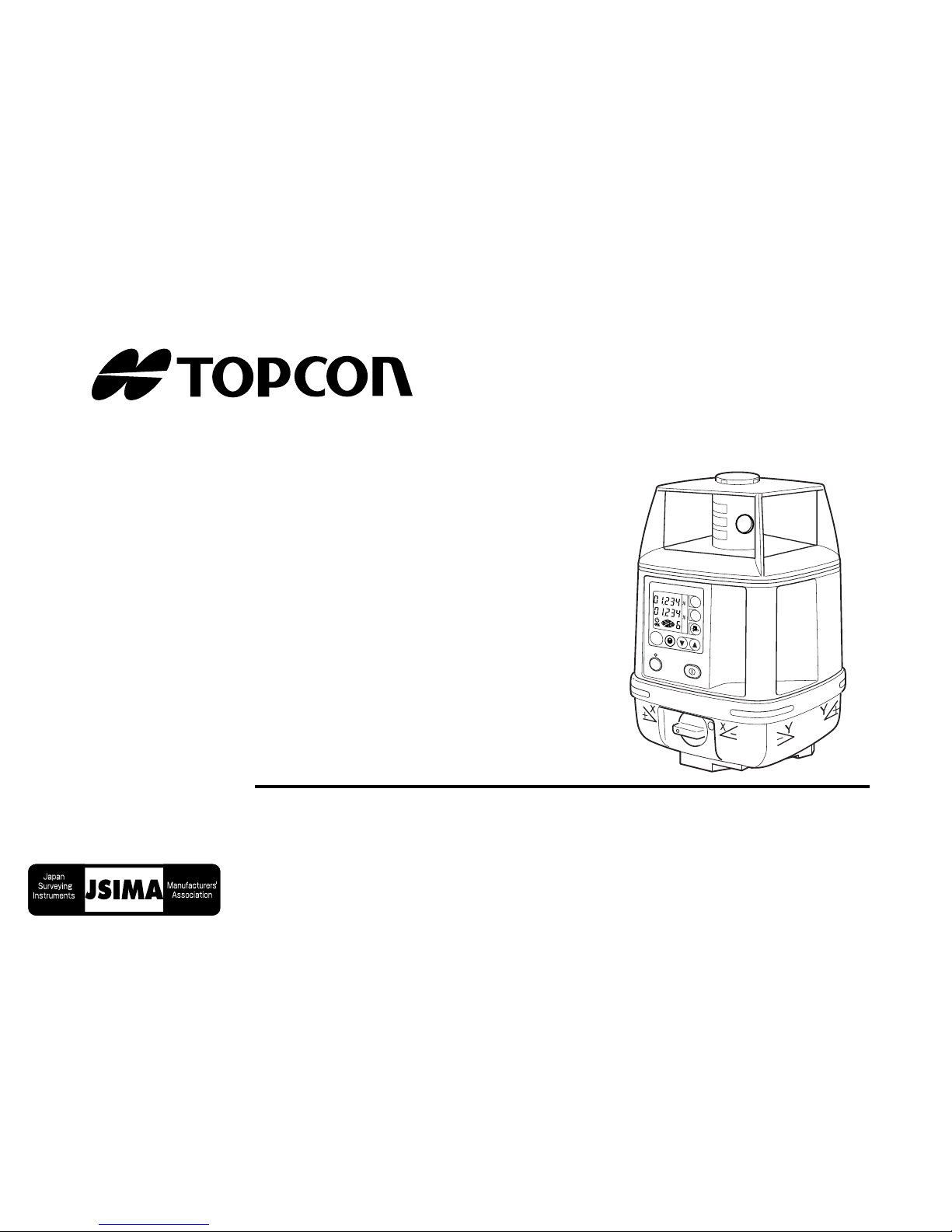
ROTATING LASER
RL-H2Sa
RL-H2Sa
ENT
ON
MANU
X
Y
x100
rpm
POWER
Page 2

Page 3

Foreword
Thank you for purchasing the Topcon RL-H2Sa Rotating Laser.
It is one the world’s most advanced lasers.
To quickly and effectively use the RL-H2Sa, please read these brief instructions carefully, and keep them in a convenient location for future reference.
Handling Precautions
Before starting work or operation, be sure to check that the instrument is functioning correctly with normal performance.
1 Vibration and Impact Protection
When transporting the instrument, provide protection to minimize risk of severe vibration or impact.
Severe vibration or impacts may affect beam accuracy.
2 Storing the instrument for long period
Remove the batteries from the instrument when you will not be using it for long period.
Caution:
Use of adjustment controls or performance procedures other than those specified herein
may results in hazardous radiation exposure.
1
Page 4
Safety Information
In order to ensure the safe use of this product, prevent any danger to the operator or others,
or damage to property, impor tant warnings are placed on the product and inserted in the
instruction manual.
We recommend that you become familiar with the meaning of these Warnings and Cautions
before continuing.
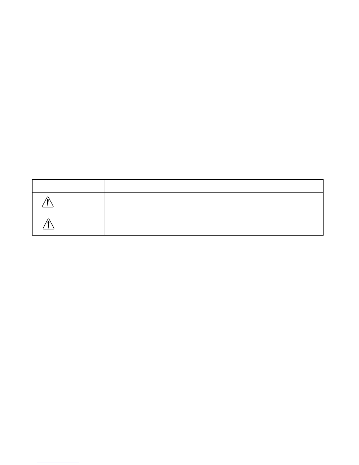
Display
Meaning
Ignoring or disregarding of this display may lead to death or seri-
WARNING
ous injury.
Ignoring or disregarding of this display may lead to personal injury
CAUTION
Injury refers to hurt, burn, electric shock, etc.
Physical damage refers to damage to equipment, structure or furnishings.
or physical damage to the instrument.
2
Page 5
Safety Precautions
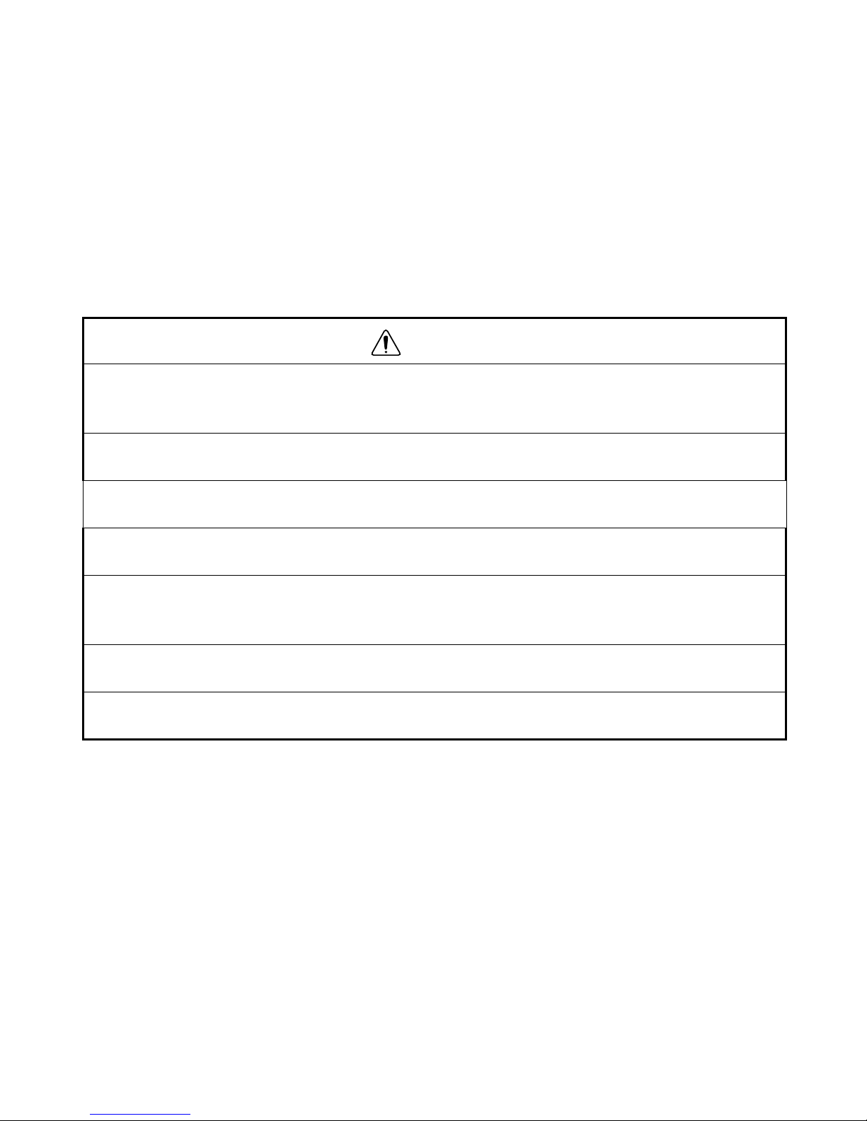
WARNING
• There is a risk of fire, electric shock or ph ysical harm if y ou attempt to disassemble or repair the instrument yourself.
Repairs are to be carried out by TOPCON or an authorized dealer ONLY!
• Laser beams can be dangerous and can cause eye injury if used incorrectly.
Never attempt to repair the instrument yourself.
• Laser beams can be dangerous. They can cause eye injury.
Do not stare into beam or view directly with optical instruments.
• Risk of fire or electric shock.
Do not use a wet battery.
• May ignite explosively.
Never use an instrument near flammable gas or liquid matter, and do not use in a coal
mine.
• Battery can cause explosion or injury.
Do not dispose in fire or heat.
• Short circuits can cause a fire.
Do not allow a battery to contact other objects when storing it.
3
Page 6
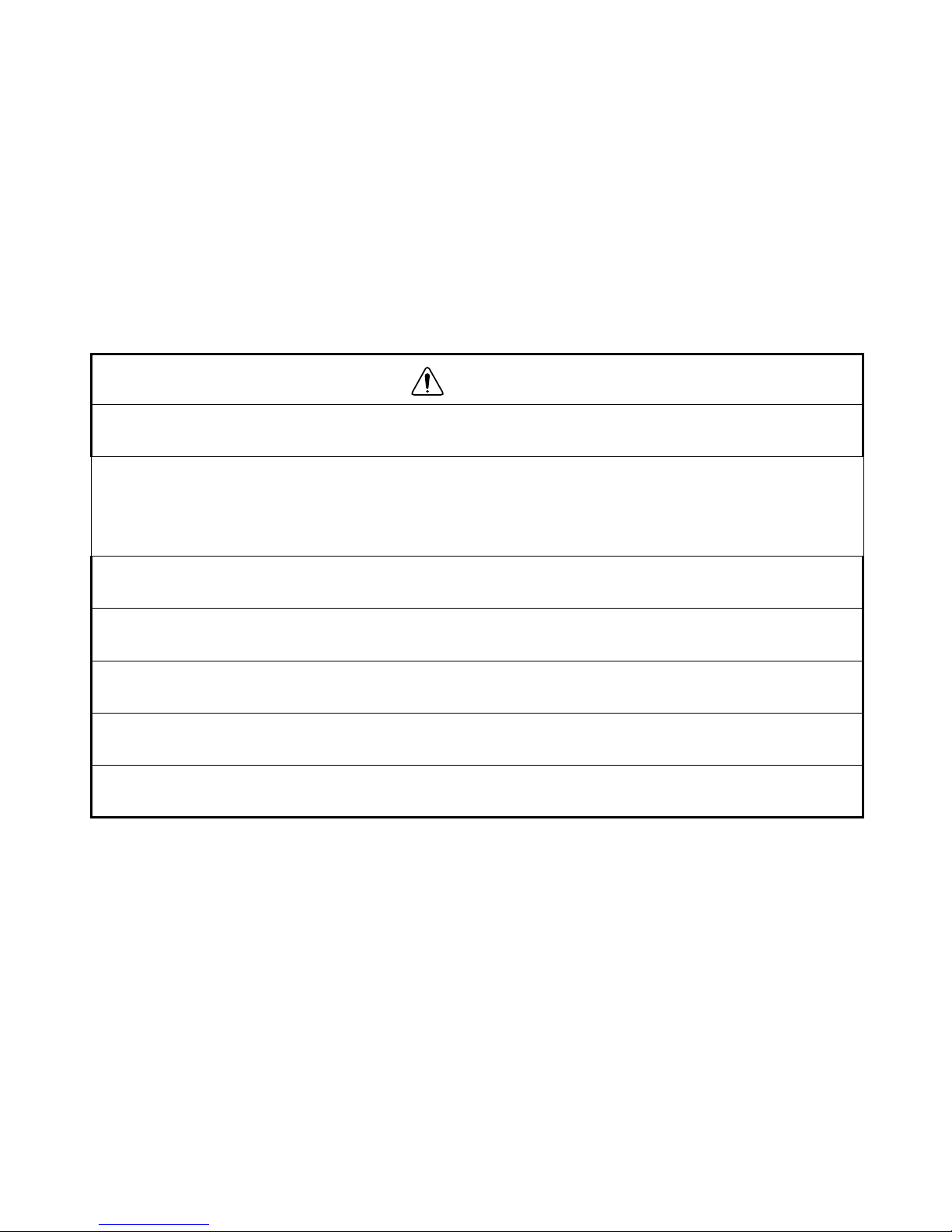
CAUTION
Use of controls, adjustment to the laser , or the performing of any procedures other than
those specified herein may result in hazardous radiation exposure.
DO NOT allow anyone to work directly in the path of the laser beam.
Always make sure the laser is operating above the height of your crews heads.
Exposure to laser light may cause momentary blindness. Always use caution when operating equipment near a laser.
Do not allow skin or clothing to come into contact with acid from the batteries. If this occurs, wash off with copious amounts of water and seek medical attention.
Damaged or broken carrying cases may fall open causing injury, or damage to the laser.
Do not use a carrying case with damaged belts, grips or latches.
It could be dangerous if the instrument falls off of its mount. Please chec k that y ou have
mounted the instrument to the wall mount or tripod securely and correctly.
An unstable tripod can pose a potential risk of injury or damage to the laser.
Always check that screws or leg locks are tight and tripod is sitting firmly.
Please note that the tips of tripod can be hazardous and be aware of this when setting
up or carrying the tripod.
4
Page 7

User Precautions
1
Always wear protective clothing (safety shoes, helmet, etc.) when operating.
Exceptions from Responsibility
1
The user of this product is expected to f ollow all operating instructions and mak e periodic checks of the
product’s performance.
2
The manufacturer, or its representatives, assumes no responsibility f or results of a faulty or intentional
usage or misuse including any direct, indirect, consequential damage, and loss of profits.
3
The manufacturer, or its representatives, assumes no responsibility for consequential damage, and
loss of profits by any disaster, (an earthquake, storms, floods etc.), fire, accident, or an act of a third
party and/or a usage in other than usual conditions.
4
The manufacturer, or its representatives, assumes no responsibility f or any damage , and loss of profits
due to a change of data, loss of data, an interruption of business etc., caused by using the product or
an unusable product.
5
The manufacturer, or its representatives, assumes no responsibility f or any damage , and loss of profits
caused by usage other than explained in the user manual.
6
The manufacturer, or its representatives, assumes no responsibility for damage caused by wrong
movement, or action due to connecting with other products.
5
Page 8
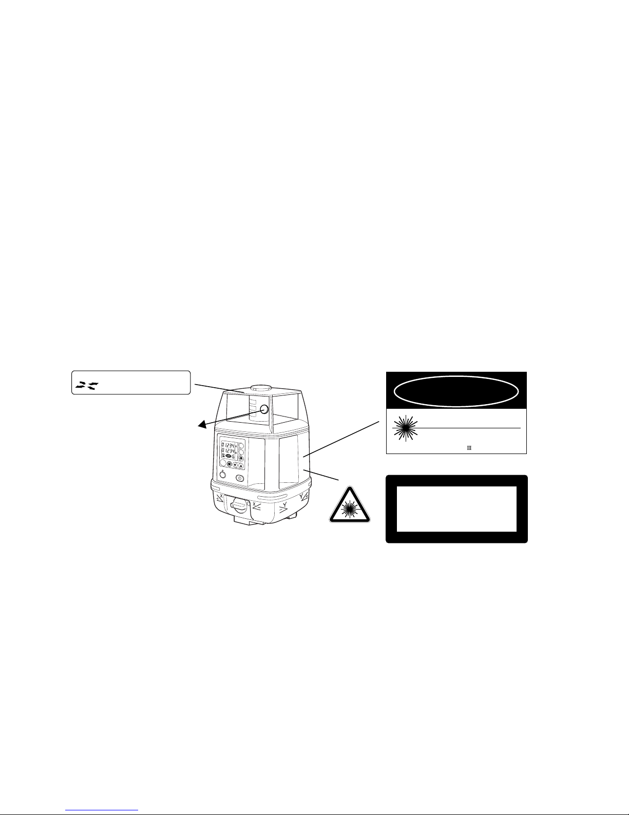
Laser Safety
This product uses a invisible laser beam, and is manufactured and sold in accordance with
“Performance Standards for Light-Emitting Products” (FDA/BRH 21 CFR 1040) or “Radiation
Safety of Laser Products, Equipment Classification, Requirements and User’s Guide” (IEC
Publication 825) provided on the safety standards for laser products.
As per the said standard, this product is classified as a “Class 3A (IIIA) Laser Product”.
This is a simple product to operate and does not require training from a laser safety officer.
In case of any failure, do not disassemble the instrument. Contact TOPCON or your TOPCON dealer.
Labels
AVOID EXPOSURE
LASER LIGHT IS EMITTED
FROM THIS APERTURE
DANGER
LASER RADIATION
WAVE LENGTH 685nm
5mW MAXIMUM OUTPUT
CLASS a LASER PRODUCT
Beam aperture
ON
ENT
MANU
RL-H2Sa
AVOID DIRECT EYE EXPOSURE
X
Y
x100
rpm
POWER
LASER RADIATION
DO NOT STARE INTO BEAM
Maximum output5mW Wave length 685nm
CLASS3A LASER PRODUCT
Labels are differed by the market.
6
Page 9

Contents
Foreword ............................................1
Handling Precautions ...................................1
Safety Information ........................................2
Safety Precautions .......................................3
User Precautions .........................................5
Exceptions from Responsibility ....................5
Laser Safety .................................................6
Contents ......................................................7
Standard System Components ....................8
Nomenclature and Functions ...........9
RL-H2Sa ...................................................... 9
Control Panel ............................................10
Basic Operation .................................11
Preparation and Functions ...............12
Battery Installation .......................................12
Instrument Set-up Procedure .......................12
Battery Warning Indicator ............................13
Auto-leveling lamp .......................................14
To turn automatic leveling off ....................14
Inclination Warning ......................................15
Changing rotation speed .............................16
Height Alert function ....................................16
To activate the height alert function ..........16
Aligning Direction of Grade ..........................17
Entering Grade ............................................18
How to enter grade ................................... 19
Masking (Laser beam shutter) .................... 21
Maintaining Power Sources .............22
Installing ...................................................... 22
Charging ...................................................... 22
Checking and Adjusting Calibration 24
Horizontal Calibration .................................. 24
(1) Checking Calibration ........................... 24
(2) Adjusting Calibration ........................... 26
Horizontal Rotation Cone Error ................... 31
Grade Setting Error ..................................... 32
(1) Checking ............................................. 32
Storage Precautions .........................35
Standard / Optional Accessories .....36
Laser sensor holder model 5 .................... 36
Laser sensor holder model 3 .................... 36
LS-70A Laser Sensor ............................... 37
LS-70B Laser Sensor ............................... 37
Scope Model 3 .......................................... 40
Rechargeable battery holder DB-51 ......... 41
Error Code ..........................................42
Specifications .................................... 43
RL-H2Sa ..................................................... 43
Laser Sensor LS-70A/B .............................. 44
7
Page 10

Standard System Components
1 RL-H2Sa .......................................................................................1pc.
2BT-51Q (Ni-MH) Rechargeable battery.................................................1pc.
3 DB-51C Rechargeable battery holder...................................................1pc.
4 AD-9B/7C AC/DC converter .................................................................1pc.
5 LS-70B Laser Sensor ...........................................................................1pc.
6 Laser Sensor holder, model 3...............................................................1pc.
7 Carrying case .......................................................................................1pc.
8 Instruction manual.................................................................................1vol.
Please make sure that all of the above items are in the box when you unpack.
8
Page 11
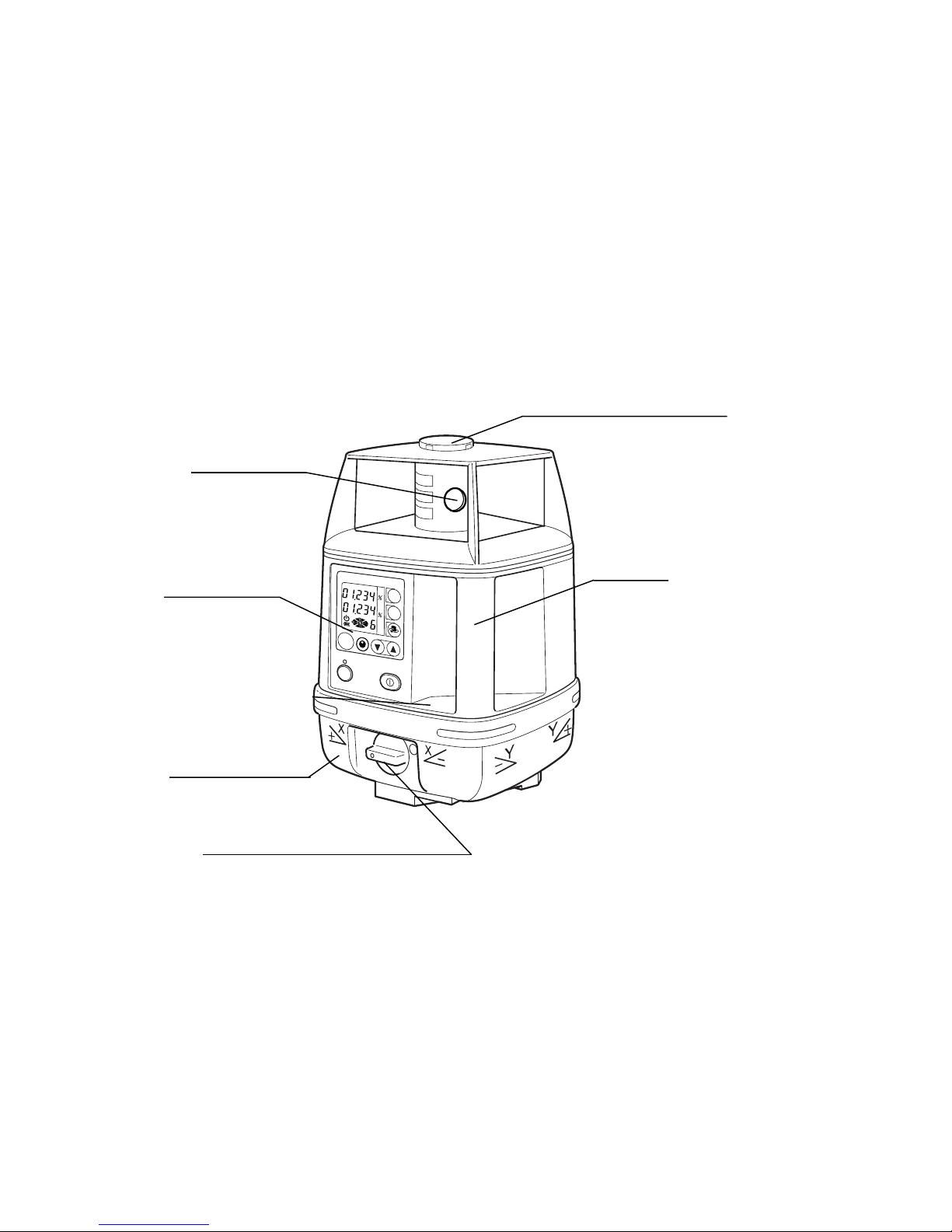
Nomenclature and Functions
RL-H2Sa
Rotary head
Beam aperture
Grade alignment sights
Control Panel
Battery holder
Battery compartment lock
RL-H2Sa
ENT
ON
MANU
Handle
X
Y
x100
rpm
POWER
9
Page 12
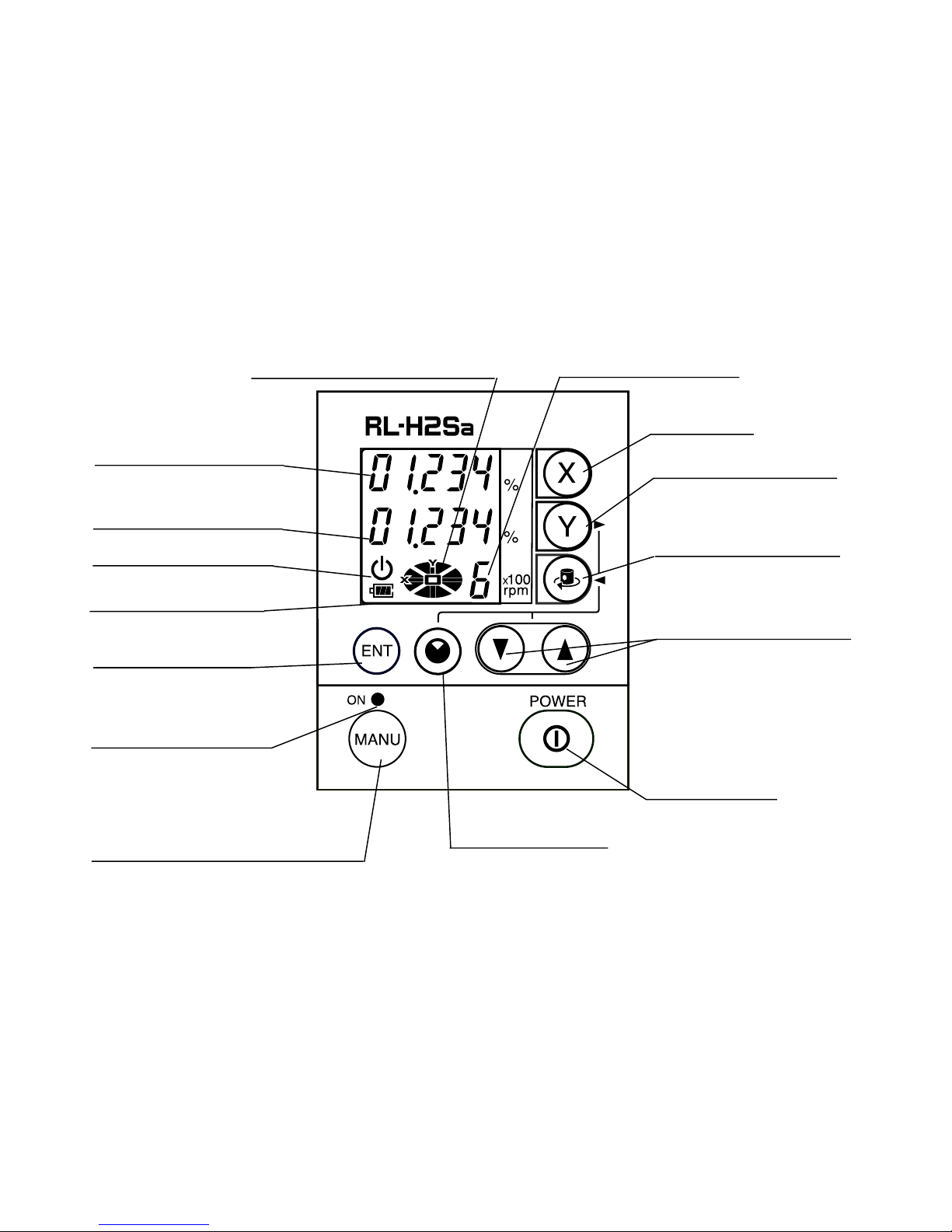
Control Panel
Masking direction indicator
X-axis grade display
Y-axis grade display
Auto leveling indicator
Battery indicator
Enter key
Manual mode lamp
Rotation speed
X-axis key
Y-axis key
(Arrow key for Mask
quadrant 4)
Rotation control key
(Arrow key for Mask
quadrant 2)
Arrow keys
• Changes rotation speed
• Changes grade setting
• Controls mask quadrants 1 and 3
Power key
Auto/manual leveling key
10
Mask key
Page 13
Basic Operation
X
rpm
100
MANU
×
POWER
%
ON
ENT
1
Set the RL-H2Sa on a tripod or flat surface.
(See "Instrument Set-up Procedure " on page
12.)
2
Turn the instrument ON and enter a grade if
desired. (See "Entering Grade " on page 18.)
3
Set beam rotation to the desired speed.
(See "Changing rotation speed " on page 16.)
4
Set the electronic beam shutter (mask) for specific quadrants if desired. (See "Masking
(Laser beam shutter) " on page 21.)
5
Turn on LS-70 laser sensor. If high-precision
detection is desired, select that setting on the LS-70.( See "Standard / Optional Accessories " on page 36 for more information.)
6
Use the LS-70 to intercept the rotating laser beam to check a specific elevation.
11
Page 14
Preparation and Functions
Battery Installation
For battery installation instructions, see "Maintaining Power Sources " on page 22.
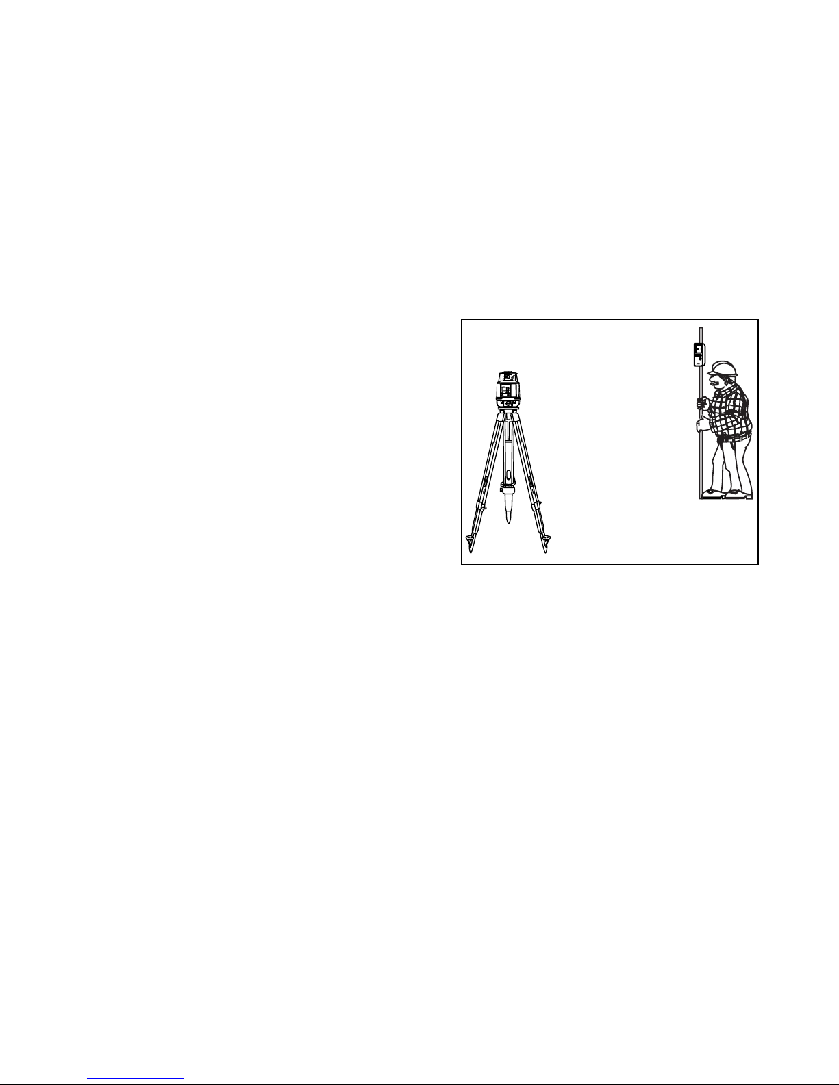
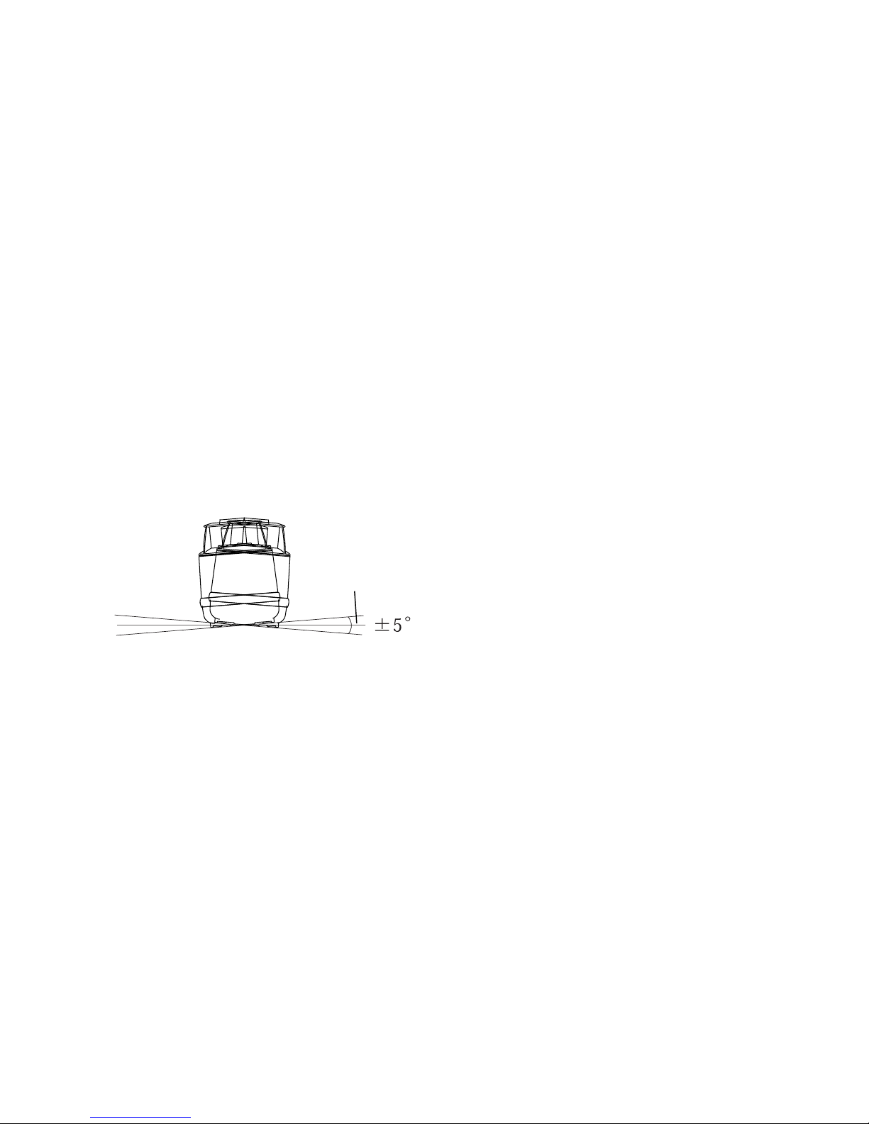
Instrument Set-up Procedure
1
Set the instrument on any smooth surface that is within ±5° of true level. The RL-H2Sa
auto-level system will not function if the unit is placed more that 5° out of level. For best
operation, it is recommended that it be mounted to a tripod. Beam slope can be set in the
X-axis (See "Entering Grade " on page 18.
Horizontal
Leveling range
12
)
Page 15
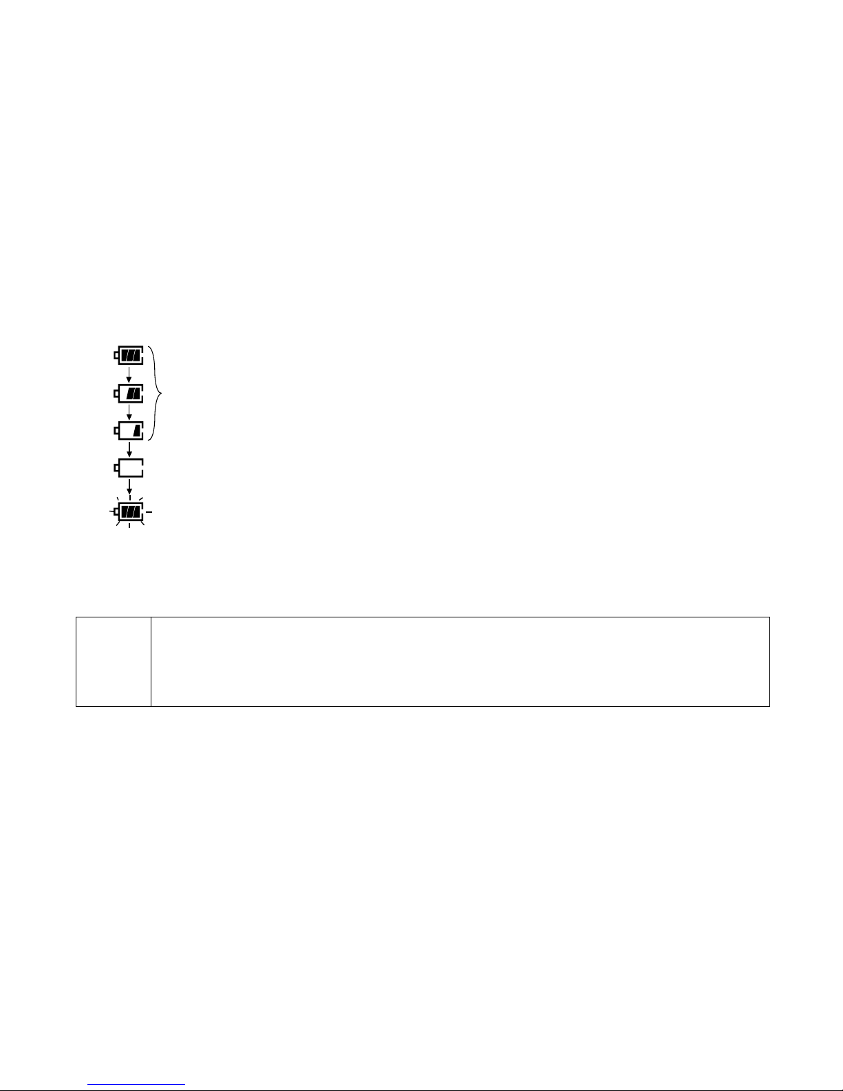
Battery Warning Indicator
The Battery warning indicator indicates the battery power remaining.
Battery is sufficient.
The power is low, but laser is still usable.
In this state, the laser will transmit the battery warning signal to laser sensor.
AC/DC converter AD-9B or AD-7C is available for continuing the operation.
Dead batteries. The rotary head stops and no beam is emitted from the laser.
Blinking
Recharge the battery (BT-51Q Ni-MH rechargeable battery) or replace the dry batteries with
new ones. (The laser will shut down a few minutes after the blinking indicator comes on.)
AC/DC conv erter AD-9B or AD-7C is availab le but it is necessary to turn OFF the instrument
once, and turn ON the instrument again.
Note
• When BT-51Q (Ni-MH rechargeable battery) is used, the blinking period will be
shorter because of the characteristic of the battery.
• The LS-70A and LS-70B laser sensors can detect and signal low power state
of laser.
13
Page 16

Auto-leveling lamp
Flashing : Auto-leveling is in process. When automatic leveling is almost complete,
the flashing rate will be slow. The head will not rotate and the laser beam will
not emit during the auto-leveling process.
ON Solid:Auto-leveling is complete.
The rotary head is active and emits the laser beam.
To turn automatic leveling off
To turn OFF the auto-leveling function (manual mode), press the Auto/Manual leveling control pad twice in quick succession. The manual mode indicator light will illuminate. The instrument can be positioned in any direction and the laser beam remains on and the head will
rotate.
IMPORTANT
leveling mode, press Auto/Manual control pad once.
: In manual mode, the laser beam will not shut off if disturbed! To return to Auto-
14
Page 17

Inclination W arning
X
rpm
100
MANU
×
POWER
%
ON
ENT
If the instrument is inclined out of automatic grading range (usually approximately ±5°, but
±2
°
according to the set grades).
The Auto-leveling lamp will flash and the grades will disappear. Set the instrument as horizontally as possible and turn off/on the instrument again. (This war ning may be displayed
about six minutes or more after powering ON.)
.
Blinking
15
Page 18

Changing rotation speed
Press Rotation Control key to activate rotation speed mode. Select the rotation speed 300 r.p.m, 600 r.p.m or 900 r.p.m by pressing the arrow keys.
Press the Enter key to accept the setting.
Height Alert function
When auto-leveling and height alert function are active, this function prevents
the instrument from operating if it is disturbed. This insures accurate control. If the unit is disturbed, all displays and Auto-leveling lamp will flash. The elevation (height of instrument)
should be verified and re-established if necessary.
Note
• The LS-70A and LS-70B laser sensors can detect and signal the height alert
warning.
To activate the height alert function
To activate the height aler t function, depress and hold the Manual key [MANU] while turning
on the instrument by pressing the Power key. The display will show “HiON” for two seconds
before starting auto-leveling. Height alert function will be tur ned ON automatically after 10
minutes since the auto-leveling is completed.
Turn the power key OFF and ON again, the height alert function will be de-active again.
16
Page 19

Aligning Direction of Grade
When using the laser with a percent of grade entered,
the laser must be properly aligned so the slope of the
laser beam is parallel to the desired direction of grade.
The sighting collimator on top of the instrument is calibrated to the grade axis of the laser beam. Follow the
steps below to align the laser to the desired direction of
grade:
1
Establish a target line parallel to desired direction of
grade.
2
Set up the laser over this line (drop a plumb bob from
the tripod mounting screw).
3
Rough align the instrument to the direction of grade.
Make sure it is properly oriented for the grade to be
entered, positive or negative. (See page 18)
4
Place a rod or other target down range on the target line.
5
While sighting through
the collimator, adjust the
instrument until the sight
is aligned with the target. (see right)
Target
Plus direction
Minus direction
17
Page 20

Entering Grade
Y
X
rpm
100
MANU
×
POWER
%
%
ON
ENT
The laser beam can be sloped in either the X or Y axis (single slope) or both axes (compound slope).
Grade range: Single axis: -8.000 to +8.000%, Dual axes: |X| + |Y| ≤ 10.000%
Compound slope
18
Plus (+)
+8%
- 8%
Minus (-)
Plus (+)
+8%
- 8%
Minus (-)
Single Axis
X axis
Y axis
Dual Axes
Control Panel side
- 8%
+8%
- 8%
+8%
Minus (-)
X axis
Horizontal
Plus (+)
Minus (-)
Y axis
Horizontal
Plus (+)
Page 21

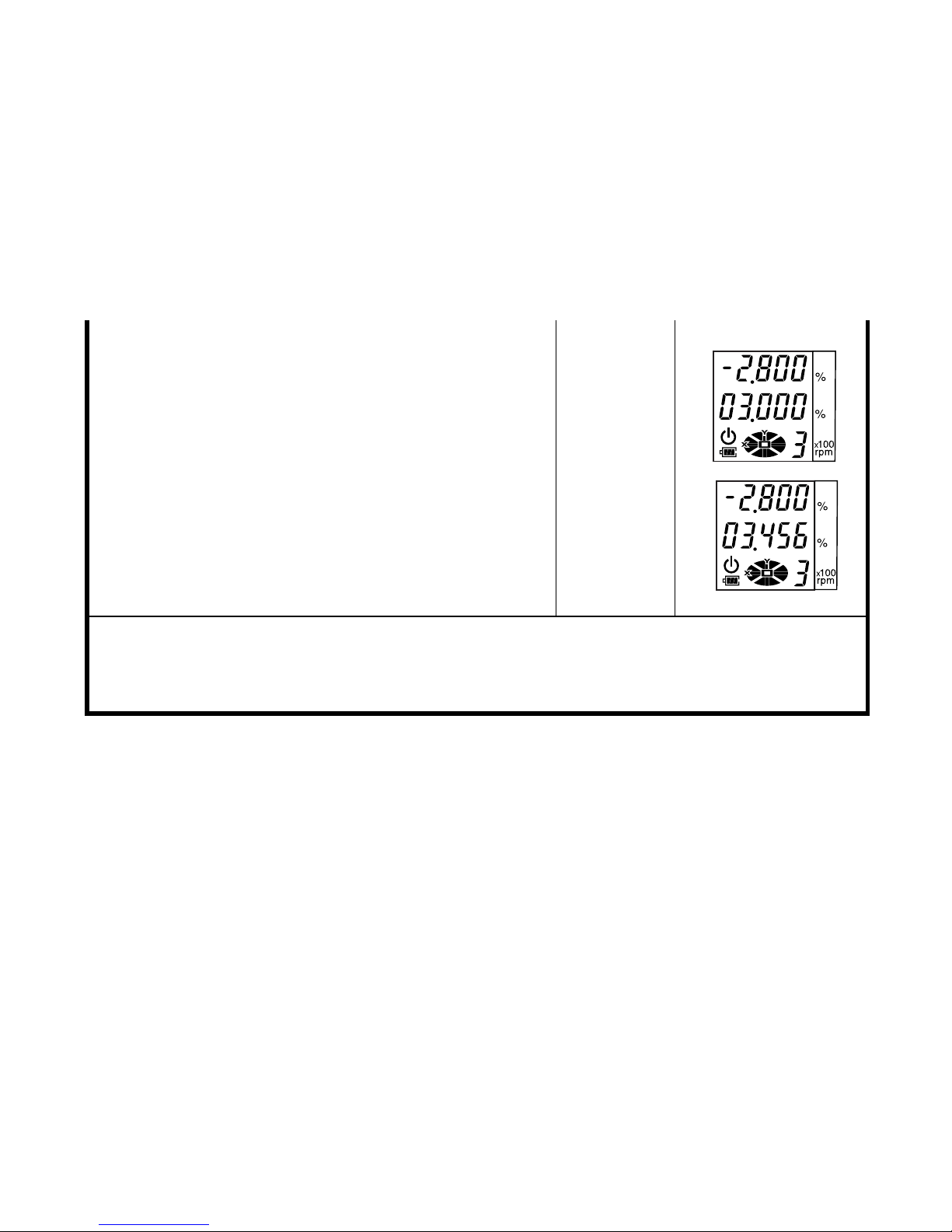
How to enter grade
Setting example: Grade toward X-axis -2.800%, Y-axis -3.456%
Operating procedure Operation Display
1
Turn the instrument on by pressing the power control pad. Auto-leveling will start.
2
Press the [ X] key to activate grade entry.
The position of the second figure to the left of the
decimal point will blink.
3
Press the [▲] or [▼] key to set "-" (negativ e grade).
4
Press the [X] key to activate the first figure to the
left of the decimal point.
5
Press the [▲] key twice to set ‘2’.
6
Press the [X] key to activate the first figure to the
right of the decimal point.
7
Press the [▼] key twice to set ‘8’.
8
Press the [ENT] key to accept the X-axis grade.
Power ON
[X]
[▲]or[▼]
[X]
[
▲
]twice
[X]
[
▼
]twice
[ENT]
19
Page 22
9
Press the [ Y] key to to activate grade entry.
The position of the second figure to the left of the
decimal point will blink.
10
Press the [Y] key to activate the first figure to the
left of the decimal point.
11
Press the [▲] key three times to set ‘3’.
12
Input the next figures in the same manner.
13
Press the [ENT] key to accept the Y-axis grade.
• Grade range: Single axis, -8.000% to +8.000%; Dual axes, |X| + |Y| ≤ 10.000% grade.
• After grade entry is completed, it will take about two minutes for the beam to reset and
rotation to begin. DO NOT touch or tilt the instrument during automatic leveling as it will
disturb the precision of the leveling.
[
▲
] 3times
[ENT]
[Y]
[Y]
20
Page 23
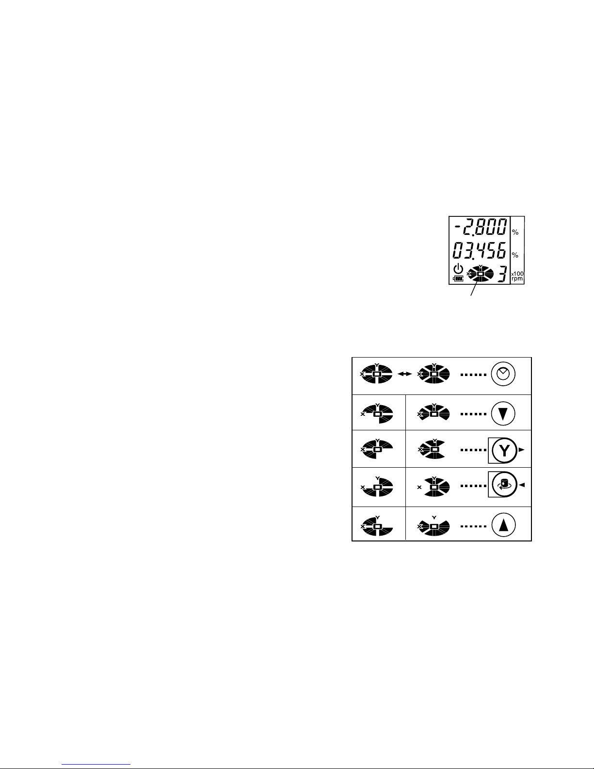
Masking (Laser beam shutter)
The RL-H2Sa features electronic beam “masking” to prevent the
beam from transmitting on one or multiple sides of the instrument.
This can be useful to eliminate duplicate laser beams on job sites
where more than one laser may be in use.
The beam plane is divided into four masking quadrants as indicated
on the masking display. The direction of the four masking quadrants
can be set as shown below.
1
Press the Mask key.
2
To change the masking direction mode, press the
Mask key again.
Each press toggles between the two masking
direction modes.
3
To mask a specific quadrant, press the arrow key
that corresponds to that quadrant.
Each press toggles between activating and
releasing the mask for that quadrant.
4
To mask additional quadrants, repeat step 3 with
Mask display
and Direction
Mask display
Operation keys
the arrow key for that quadrant.
5
Press the Enter key to accept the masking settings.
21
Page 24
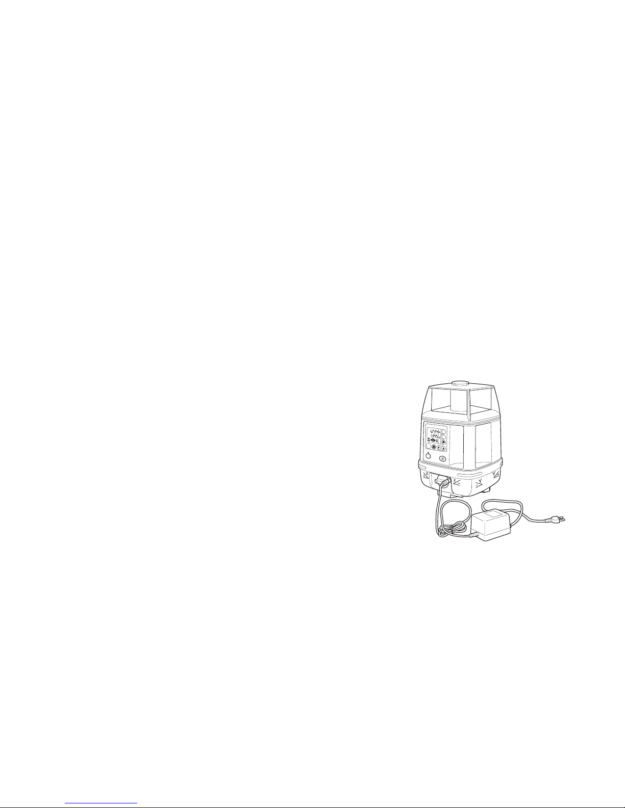
Maintaining Power Sources
Installing
1
Insert the BT-51Q rechargeable battery into the instrument.
2
Place the DB-51C rechargeable battery holder firmly into the instrument and turn the battery cover knob to “LOCK”.
Charging
1
Plug the AC/DC converter (AD-9B or AD-7C) into the charger jack on the DB-51C
rechargeable battery holder.
2
Plug the convertor cord into a proper power outlet
(AD-9B is for AC120V, AD-7C is for AC230V)
3
Complete charging by unplugging the conv erter connector from the DB-51C rechargeable battery holder
after approximately 9 hours.
4
Unplug the converter from the outlet.
The DB-51C LED will indicate charging status as follows:
DB-51C
RL-H2Sa
X
Y
x100
rpm
ENT
ON
POWER
MANU
Red ON : Charging
Green ON : Charging completed
Green flashing : DB-51C is not connected to BT-51Q rechargeable battery.
22
AC/DC converter AD-9B/7C
Page 25

Red flashing : BT-51Q protection feature is working automatically.
RL-H2Sa can be used in this state.
Automatic protection f eature; In case of overcharge or high or low temperature state e xceeding charging range, charging will be stopped or changed to protect battery.
1)
Note
The RL-H2Sa can be charged while using the laser.
2)
Alkaline batteries can be used with the DB-51C rechargeable battery
holder.
3)
Recharging should take place in a room with an ambient temperature
range of 10°C to 40°C (50°F to 104°F).
4)
The battery source will discharge when stored and should be checked
before using with instrument .
5)
Be sure to charge stored battery source every 3 or 4 months and store in
a place at 30°C (60°F) or below. If you allow the battery to be completely
discharged, it will have an effect on future charging.
6)
Recharging of the BT-51Q may sometimes take less than 9 hours because of its remaining capacity at time of charging.
23
Page 26
Checking and Adjusting Calibration
MANU
POWER
ON
ENT
Y
X
rpm
100
×
%
%
There are three areas of performance the user should check periodically.
Horizontal Calibration
Horizontal Rotation Cone
Grade Setting Error
The Horizontal Calibration can be easily checked and, in most cases, adjustments can be
made by the user. Horizontal Rotation Cone and Grade Setting Error can be checked by the
user. However, if an error is found, adjustments must be made by a Topcon service facility.
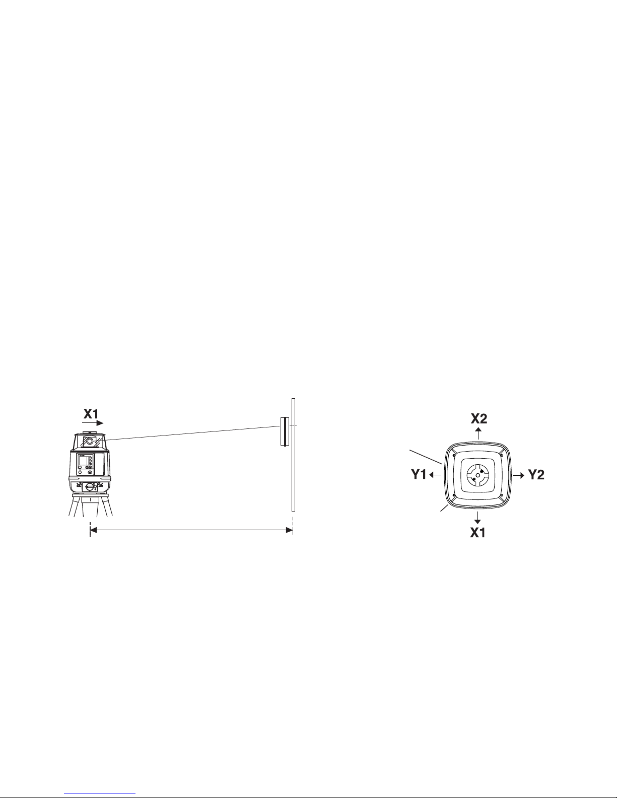
Horizontal Calibration
(1) Checking Calibration
Instrument as seen from above
Laser Beam
at X1
Level
Sensor
Wall
50m (160feet)
1st
On-Grade
Position
Panel side
Handle
1 Set up a tripod 50m (160ft) from a wall. Mount the instrument on the tripod, facing the X1
side toward the wall.
24
Page 27

2 Turn the unit on and allow auto-le veling to complete. Con
MANU
POWER
ON
ENT
Y
X
rpm
100
×
%
%
-
firm that the grade is set to 00.000%.
3
Put the laser sensor in fine detection mode by pressing
the mode switch.(See page 37.)
4
Position the sensor so that it “finds” the rotating laser
beam and signals “on-grade” by displaying a horizontal
bar and emitting a continuous beep.
5
Mark the “on-grade” position and turn off the instrument.
6
Loosen the tripod screw , rotate the instrument 180 degrees and re-secure it on the tripod.
Note
7
Turn the unit on again and allow
• When rotating the instrument, avoid knocking it off level or changing height.
auto-leveling to complete. Confirm
the grade is set to 00.000%.
8
Position the sensor so that it “finds”
the rotating laser beam and signals
“on-grade”.
9
Mark the on-grade position (X2).
10
Measure the distance between the
first mark (X1) and your second
X1 laser beam
X2 laser beam
50m (160feet)
1st
On-Grade
Position (X1)
If less than
5mm( 0.2
inches)
No calibration
Necessary
2nd
On-Grade
Position (X2)
25
Page 28
mark (X2). No calibration is necessary if distance is within 5mm (0.2 inches).
If the distance is greater than 5mm (0.2 inches), adjust as follows.
11
Repeat procedure for the Y axis.
26
Note
• Please contact your Topcon dealer if the distance between the first and second mark exceeds ±40mm (1.6 inches).
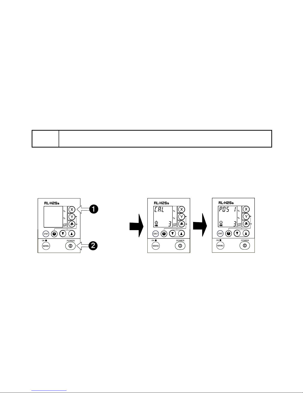
(2) Adjusting Calibration
To calibrate the X axis:
1
Press the Power button once to turn off the laser.
Turn the laser back on b y pressing the Power button down while pressing the X AXIS b utton. This activates the X axis calibration mode. Confirm that rotation speed is set to 1.
Press and
Hold
Press
2
After the “CAL” display changes to “POS 1”, move the level sensor up or down until it
“finds” the rotating laser beam and signals “on-grade”.
Page 29

Note
MANU
POWER
ON
ENT
Y
X
rpm
100
×
%
%
MANU
POWER
ON
ENT
Y
X
rpm
100
×
%
%
3
When the sensor signals “on-grade”, secure its position.
• When the instrument has auto-leveled, the “POS 1” will stop flashing.
Move Level Sensor Up
or Down Until Beam is
Detected.
50m (160 feet)
4
Press the ENT key. The display will change to “POS 2”.
PRESS
ENTER
When Beam is
Detected, Fix Level
Sensor.
50m (160 feet)
27
Page 30
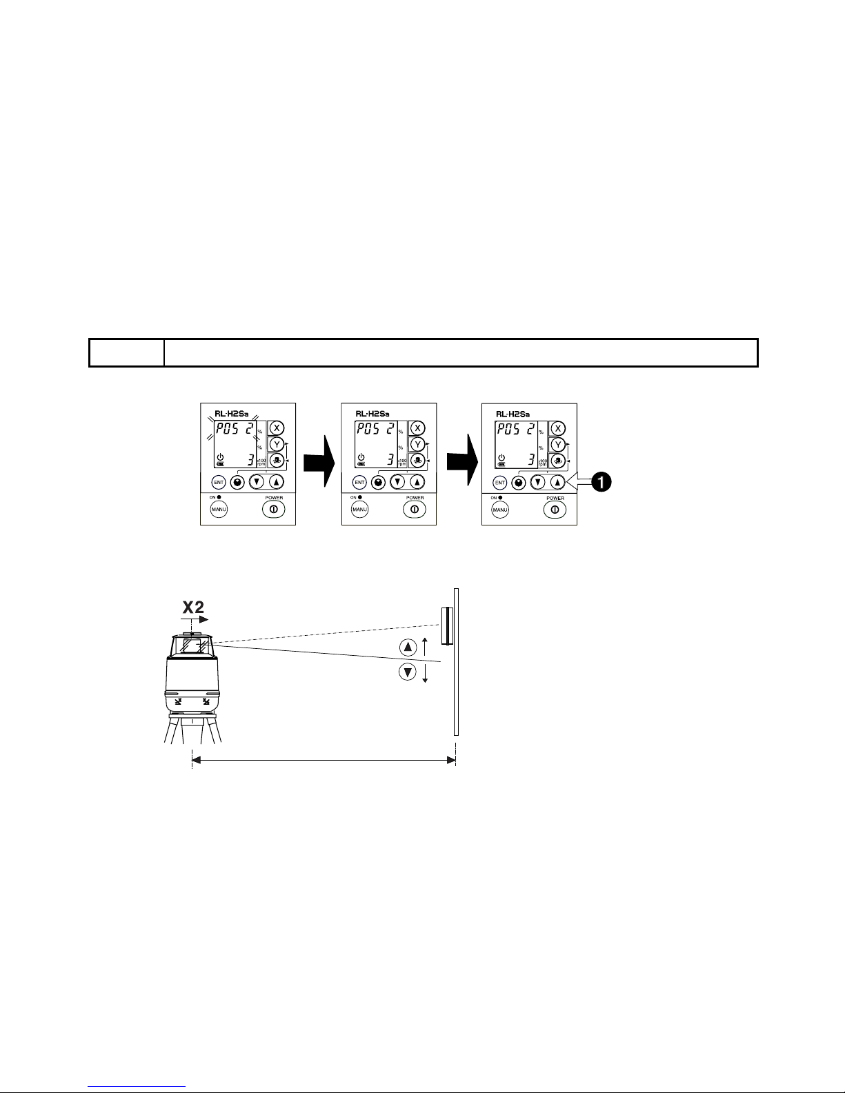
5
When “POS 2” is displayed, rotate the instrument 180 degrees; the instrument will selflevel. When the instrument has auto-leveled, the “POS 2” will stop flashing.
Note
6
Adjust the laser beam to the sensor so that an “on-grade” signals is displayed. To adjust
• When rotating the instrument, avoid knocking it off level or changing height.
PRESS ▲ OR ▼
BUTTON T O MOVE
BEAM
the position of the laser beam, press the up or down arrows on the panel.
X1 laser beam
X2 laser beam
50m (160feet)
Align Beam to
Fixed Laser
Sensor
28
Page 31

"On-grade signal means X2 beam has been
adjusted to same elevation as X1 beam.
50m (160feet)
7
When a continuous "on-grade" signal is achieved, press the ENT key. “CALC” will appear
in the display. Keep the instrument as it is until an error correction value appears. (If the
instrument was disturbed during the calculation, you will need to re-start the adjustment
process.) After a short time, “CAL END” will appear.
PRESS
ENTER
29
Note
• If the error is greater than the self-correction range, “E72” error code will display and LEDs will blink alternately. Contact your Topcon dealer.
Page 32

8
Turn Off the instrument by pressing the Power key.
9
Turn the power ON again and follow the checking procedure again to confirm that proper
calibration has been completed.
10
Repeat the checking and, if necessary, the adjusting procedure for the Y-axis.
11
If the Y-axis requires adjustment, begin at Step 1 on page 26. However, when turning on
the instrument in calibration mode, press and hold the Y AXIS button while pressing the
Power key. This activates the Y-axis calibration mode.
30
For Y-axis
calibration
Press and
Hold
Press
Page 33
Horizontal Rotation Cone Error
X
rpm
100
MANU
×
POWER
%
ON
ENT
X
rpm
100
MANU
×
POWER
%
ON
ENT
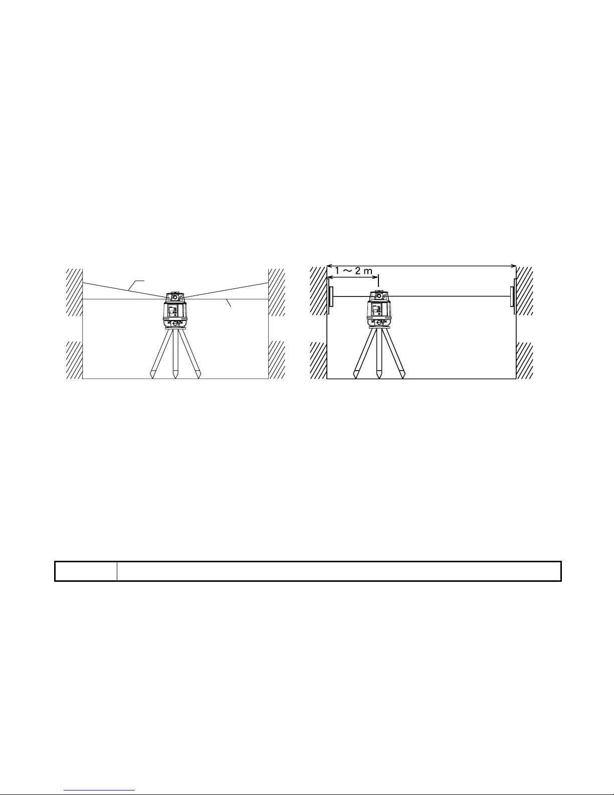
Perform the following check after completing "Horizontal Calibration" on the previous
pages.
Minimum about 40m/131ft
Cone error
Wall
Datum position
A
Set up the laser centered between two walls approximately 40m (131ft) apart. Orient the
1
Wall
B
Wall
A
Wall
B
instrument so one axis, either X or Y, is facing the walls. Confirm grade is set to 00.000%.
2
Locate and mark the position of the rotating laser beam on both walls using the laser sensor.
3
Turn off the instrument and move the instrument closer to wall A (1m to 2m /3 ft to 6 ft).
Do not change the axis orientation of the instrument. Turn the instrument on.
Again locate and mark the position of the rotating laser beam on both walls using the
4
laser sensor.
5
Measure the distance between the first and second marks on each wall.
6
If the difference between each set of marks is less than 4mm (5/32 of an inch), no error
exists.
Note
• If the error is greater than 4mm ( 5/32 of an inch), contact your Topcon dealer.
31
Page 34

Grade Setting Error
X
rpm
100
MANU
×
POWER
%
ON
ENT
Perform the following check only after completing "Horizontal Calibration" and “Horizontal Rotation Cone Error” procedures.
(1) Checking
Note
• Due to the accuracy required to perform this check, the rod used in this procedure must be graduated in millimeters.
1
Securely position two nails or stakes exactly 30m (93 ft) apart. These positions will be
called Nail 1 and Nail 2.
Laser Sensor
Rod
Nail 1
2
Set up the instrument on a tripod approximately 1m to 2m (3 ft to 6 ft) in front of Nail 1 on
Rod
Nail 2
the line created by Nail 1 and Nail 2. Position the instrument so the X-axis is exactly
aligned to the line created by Nail 1 and Nail 2.
3
Turn on the instrument and verify the grade setting is 00.000%. Turn on the LS-70 laser
sensor and set it to high precision detection. Using the rod, read the ele v ation of the laser
32
Page 35

beam in millimeters at Nail 1 and Nail 2. Designate the elevation at Nail 1 as “h1”, at Nail
X
rpm
100
MANU
×
POWER
%
ON
ENT
2 as “h2”.
4
Set X-axis grade to 1.000%. Again, read the elevation of the laser beam in millimeters at
Nail 1 and Nail 2. Designate these elevations as “h3” at Nail 1, and “h4” at Nail 2.
Nail 1
5
Using the millimeter elevation readings for h1, h2, h3 and h4, and converting the 30mm
Nail 2
distance between Nail 1 and Nail 2 to 30000mm, complete the equation below.
x(%)= (h2-h4) - (h1-h3) ✕ 100
30000 (mm)
If the calculated result is the range of 0.990% - 1.010%, the instrument is within specifica-
tions.
33
Page 36

Note
• If the calculated result is out of the range, contact your dealer or Topcon.
Example
; h1 = 1370; h2 = 1390; h3 = 1362; h4 = 1080
x(%)= (1390-1080)-(1370-1362) x 100
30000
x(%)= 310 - 8
x 100
30000
x(%)= 0.010066 x 100
x(%)= 1.006%
The X axis of instrument is normal because 1.006 is within the range 0.990 to 1.010.
34
Page 37

Storage Precautions
Always clean the instrument after use.
Use a clean cloth, moistened with a neutral detergent or water. Never use an abrasive
cleaner, ether, thinner benzene, or other solvents.
Always make sure instrument is completely dry before storing. Dr y any moisture with a soft,
clean cloth.
35
Page 38
Standard / Optional Accessories
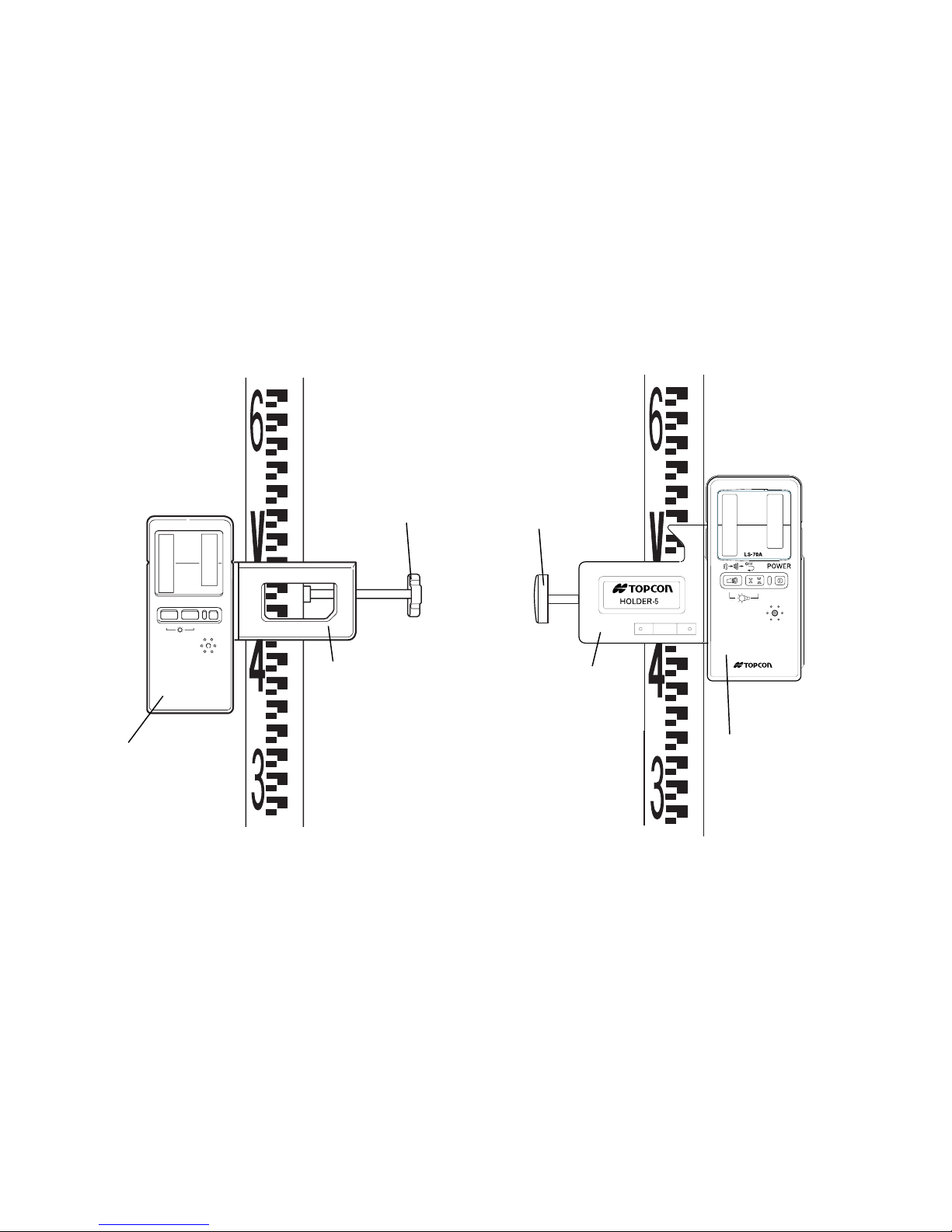
Laser sensor holder model 3
160
159
158
157
156
155
154
153
152
POWER
Laser sensor
151
150
149
148
147
143
142
139
138
137
136
135
134
133
132
131
130
129
128
127
126
125
Clamp knob
Laser sensor
holder model 3
Laser sensor holder model 5
160
159
158
157
156
155
154
153
152
151
Clamp knob
Laser sensor
holder model 5
Holder Model 5 allows the laser sensor to be moved up or
down on the rod by squeezing the spring-loaded clamp on
its back side without removing the sensor from the rod.
150
131
139
138
137
136
135
134
133
132
131
Laser sensor
130
129
128
127
126
125
36
Page 39

LS-70A Laser Sensor
LS-70B L
aser Sensor
Beam receiving window
Indicator
Beam receiving window
Indicator
On-Grade
On-Grade index
On-Grade index
index
On-Grade
precision switch
Buzzer sound
switch
(Quite/Loud/OFF)
Two on-grade precision
options are available,
normal precision and
high precision. By
pressing this switch, the
precision options are
switched alternately.
Confirm the precision
choice by the indicator.
(Normal precision is the
default setting each time
the sensor is turned on.)
Power switch
Buzzer speaker
Power switch
Illumination switch
Buzzer speaker
Buzzer sound switch
(Quite/Loud/OFF)
Auto-cut off function (LS-70A and LS-70B)
The power will be turned off automatically if no laser beam is detected within approximately 30 minutes.
(To turn the sensor on again, press the power switch.)
37
Page 40

Display (LS-70A/70B)
High precision mode
RL-H2Sa Height Alert warning *
The sensor will signal if the laser has been
disturbed so the height of the instrument
can be checked.
The buzzer will sound for about five seconds and the height alert warning symbol
will flash until the sensor detects normal
beam rotation from the laser. To obtain normal beam rotation, the RL-H2Sa must be
turned off then back on. Then check that
beam height has not changed (See page
16).
RL-H2Sa Battery warning *
The sensor will signal if the battery of the
RL-H2Sa is low. The laser low battery
warning symbol will flash on the LS-70 display. No audio signal is generated for this
warning.
*Warning detection at the LS-70 can be
canceled by turning off the LS-70, then
turning it back on while pressing the buzzer
sound switch.
Normal precision mode
Above grade indicator
Move the sensor down, The arrow will
become shorter as the on-grade position is
approached (see next page for specific
information).
Audio signal: High- pitch, frequent beep.
On-Grade indicator
(Audio signal: Continuous beep sound)
Below grade indicator
Move the sensor up, The arrow will become
shorter as the on-grade position is
approached (see next page for specific inf ormation).
Audio signal: Lower- pitch, slower frequency.
Sensor battery indicator
Indicates the battery status of LS-70A/70B
as follows.
Battery is sufficient.
The power is low, but sensor is still usable.
Flashing alternately
Dead battery. Replace the 9v alkaline battery as instructed on next page.
38
Page 41

Detective range (LS-70A/70B)
Replacing Battery (LS-70A/70B)
HIGH
LS-70A
±1mm/±.0032ft
(2mm/.0064ft width)
LS-70B
±1mm/±.0032ft
(2mm/.0064ft width)
±5mm/±.016ft
(10mm/.032ft width)
±10mm/±.033ft
(20mm/.066ft width)
±15mm/±.05ft
(30mm/.10ft width)
More than ±15mm/±.05ft
±2mm/±.0064mm
(4mm/.013 ft width)
NORMAL
1 Press the lid in the direction of the arrow
to lift.
2 Remove the battery and
replace with a new 9v
alkaline battery.
3 Press the lid down and
click to close.
Remote display with coil cord
(LS-70A option only)
Optional remote display connects to the back
of the LS-70A. The remote LCD display can
be positioned up to 5m (16 ft) from the laser
sensor.
Connector
Coil cord
Remote display
Laser sensor has been moved above or
below the laser beam.
Move sensor in direction of arrow to
receive laser.
39
Page 42
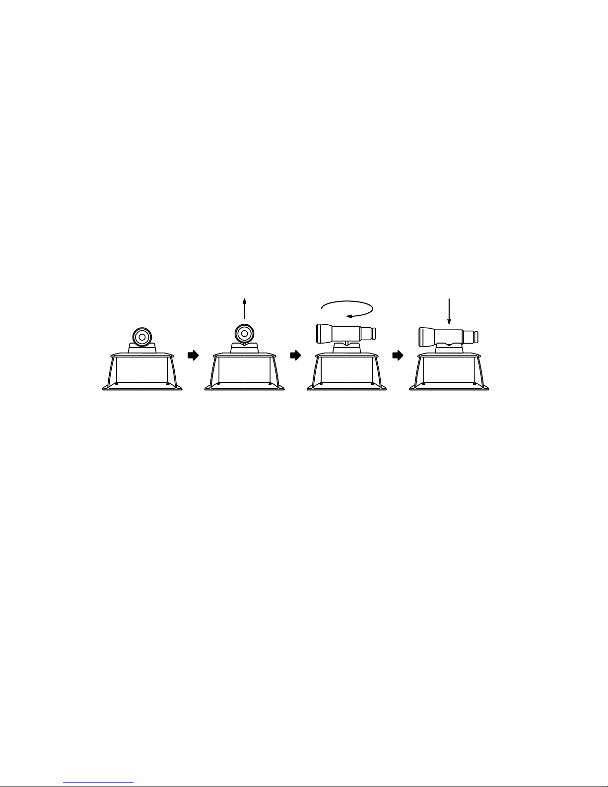
Scope Model 3
The optional scope replaces the sighting collimator (see page 17) on top of the instrument
and provides greater accuracy in aligning the laser to the direction of grade. The scope can
be swiveled and locked in place so its aimed toward any of the four beam axes. Using the
scope, follow the steps on page 17 to align the instrument.
40
Page 43

Dry battery holder DB-51
Battery lock knob
DB-51
How to replace dry batteries
1 Remove the battery holder DB-51 by turning the battery
compartment lock to “OPEN”.
2 Remove the old batteries and replace with four (4) new
“D” cell alkaline batteries making sure each is placed in
the proper direction as indicated.
3 Replace the battery holder (DB-51) and turn the knob to
“Lock”.
Note
• Replace all 4 batteries with new ones.
• Do not mix used and new batteries, and do not mix different types of batteries together.
• Insert batteries with the positive (+) and negative (-) terminals oriented correctly.
41
Page 44

Error Code
Error code Description Countermeasures
E30, 31
E62
E72
E99
If errors still persist after attempting to clear them, contact your dealer or Topcon.
Abnormal operation of tilting system
detected.
Abnormal operation of internal vertical
angle detecting system has occurred.
Calibration error is greater than selfcorrection range.
Abnormal operation of internal
memory system detected.
Turn the instrument OFF and ON
again.
Turn the instrument OFF and ON
again.
Turn the instrument OFF and ON
again and perform the calibration
again.
Turn the instrument OFF and ON
again.
42
Page 45

Specifications
RL-H2Sa
Auto-leveling range : ±5°
Beam detecting range
(When using with LS-70A/70B)
Laser source : Laser diode (visible)
Laser class : Class 3A laser product
Rotation speeds : Selectable : 300, 600, 900 r.p.m.
Grade setting range : Single axis : -8.000% to +8.000%
Power supply : 4 D-cell batteries (DC6 V),
Continuous operating time (+20°C)
Alkaline (dry) batteries
: Approx. 45 hours
Rechargeable battery BT-51Q
: Approx. 30 hours
Tripod screw : Flat and dome head type, 5”/8 × 11threads
Operating temperature : -20°C to +50°C (-4°F to +122°F)
Dimensions : 169 (L) × 169(W) × 250(H) mm
Weight : 2.7 kg [6 lbs] (with four dry batteries)
: 2m–700m diameter (6ft–2,300ft)
Dual axes : |X| + |Y| ≤ 10.000%
Rechargeable battery BT-51Q
[ 6.7(L) × 6.7 (W) × 9.8(H) in]
43
Page 46

Laser Sensor LS-70A/B
Beam detection window : 50mm (2.0 in)
Beam detection precision : High precision:±1mm(±0.04 in)
Normal precision:±2mm(±0.08 in)
Beam detection indication : Liquid crystal and buzzer
Power source : DC 9V alkaline (dry) battery
Auto shut-off delay : Approx. 30 minutes without beam detection.
Operating temperature : -20°C to +50°C (-4°F to +122°F)
Continuous operating time at +20°C (68°F)
Alkaline manganese dry batteries
: Approx. 80 hours
Dimensions
LS-70A : 167(l) × 78(w) × 27(h) mm
[ 6.6(L) × 3.1 (W) × 1.1(H) in]
LS-70B : 165(l) × 78(w) × 26(h) mm
[ 6.5(L) × 3.1 (W) × 1.0(H) in]
Weight : 0.25 kg [0.55 lbs] (with dry batteries)
Remote display : Optional for LS-70A only
44
Page 47
Page 48

TOPCON AMERICA CORPORATION
CORPORATE OFFICE
37 West Century Road, Paramus, New Jersey 07652, U.S.A.
Phone: 201-261-9450 Fax: 201-387-2710 www.Topcon.com
TOPCON CALIFORNIA
3380 Industrial BLVD, Suite 105, West Sacramento, CA 95691,
U.S.A.
Phone: 916-374-8575 Fax: 916-374-8329
TOPCON MIDWEST
891 Busse Road, Elk Grove Village, IL 60007, U.S.A.
Phone: 847-734-1700 Fax: 847-734-1712
TOPCON LASER SYSTEMS, INC.
5758 West Las Positas Blvd., Pleasanton, CA 94588, U.S.A.
Phone: 925-460-1300 Fax: 925-460-1315 www.topconlaser.com
TOPCON EUROPE B.V.
Esse Baan 11, 2908 LJ Capelle a/d IJssel, The Netherlands.
Phone: 010-4585077 Fax: 010-4585045 www.topconeurope.com
TOPCON BELGIUM
Preenakker 8, 1785 Merchtem, Belgium
Phone: 052-37.45.48 Fax: 052-37.45.79
TOPCON DEUTSCHLAND G.m.b.H.
Halskestr. 7, 47877 Willich, Germany.
Phone: 02154-9290 Fax: 02154-929-111 Telex: 8531981 TOPC D
TOPCON S.A.R.L.
89, rue de Paris 92585 Clichy, Cedex France.
Phone: 01-4106 9494 (MEDICAL) 1-4106 9490 (TOPOGRAPHIE)
Fax: 01-47390251
TOPCON ESPAÑA S.A.
HEAD OFFICE
Frederic Mompou 5, ED. EUR03 08960, Sant Just Desvern Barcelona, Spain.
Phone: 93-473-4057 Fax: 93-473-3932
MADRID OFFICE
Avenida Burgos,16E, 1° 28036, Madrid, Spain.
Phone: 91-302-4129 Fax: 91-383-3890
TOPCON SCANDINAVIA A. B.
Industrivägen 4 P. O. Box 2140 43302 Sävedalen Sweden.
Phone: 031-261250 Fax: 031-268607 Telex: 21414
TOPCON (GREAT BRITAIN) LTD.
HEAD OFFICE
Topcon House Kennet Side, Bone Lane Newbury Berkshire RG14 5PX
U.K. Phone: 001-44-1635-551120 Fax: 001-44-1635-551170
TOPCON SINGAPORE PTE. LTD.
Blk 192 Pandan Loop, Pantech Industrial Complex #07-01 Singapore
128381
Phone: 2780222 Fax: 2733540 E-mail: topconts@singnet.com.sg
TOPCON AUSTRALIA PTY. LTD.
408 Victoria Road, Gladesville, NSW 2111, Australia
Phone: 02-9817-4666 Fax: 02-9817-4654
TOPCON INSTRUMENTS (THAILAND) CO., LTD.
77/162 Sinn Sathorn Tower, 37th Fl.,
Krungdhonburi Rd., Klonglonsai, Klongsarn, Bangkok 10600 Thailand.
Phone: 662-440-1152~7 Fax: 662-440-1158
TOPCON INSTRUMENTS (MALAYSIA) SDN. BHD.
Lot 226 Jalan Negara 2, Pusat Bandar Taman Melawati,
Taman Melawati, 53100, Kuala Lumpur, Malaysia.
Phone: 03-4079801 Fax: 03-4079796
TOPCON KOREA CORPORATION
Hyobong Bldg., 1-1306, Seocho-Dong, Seocho-Gu, Seoul, Korea.
Phone: 02-3482-9231 Fax: 02-3481-1928
TOPCON OPTICAL (H.K.) LIMITED
2/F., Meeco Industrial Bldg., No. 53-55 Au Pui Wan Street, Fo Tan Road,
Shatin, N.T., Hong Kong
Phone: 2690-1328 Fax: 2690-2221 E-mail: sales@topcon.com.hk
TOPCON CORPORATION BEIJING OFFICE
Room No. 962 Poly Plaza Building, 14 Dongzhimen Nandajie,
Dongcheng District, Beijing, 100027, China
Phone: 10-6501-4191~2 Fax: 10-6501-4190
TOPCON CORPORATION BEIRUT OFFICE
P. O. BOX 70-1002 Antelias, BEIRUT-LEBANON.
Phone: 961-4-523525/961-4-523526 Fax: 961-4-521119
TOPCON CORPORATION DUBAI OFFICE
Offce No. 102,Khalaf Rashd AI Nayli Bldg., 245 Abu Hail Road, Deira,Dubai,UAE
Phone: 971-4-696511 Fax: 971-4-695272
75-1 Hasunuma-cho,Itabashi-ku,Tokyo,174-8580 Japan
Phone:3-3558-2520 Fax:3-3960-4214 http:// www.topcon.co.jp
TOPCON CORPORATION
31327 90050 RL-H2Sa 0103(3C)
 Loading...