

Page 1
Page 2

Net-G5
Operator’s Manual
Part Number 1004636-01
Rev C
©Copyright Topcon Positioning Systems, Inc.
August, 2015
All contents in this manual are copyrighted by Topcon Positioning Systems, Inc. All rights reserved.
Page 3

• • • • • •
Table of Contents
Table of Contents . . . . . . . . . . . . . . . . . . . . . . . . . . . . . . . . . . . . . . . . . . . . . . . . . . . . . . .i
Preface . . . . . . . . . . . . . . . . . . . . . . . . . . . . . . . . . . . . . . . . . . . . . . . . . . . . . . . . . . . . . . .iv
Terms and Conditions. . . . . . . . . . . . . . . . . . . . . . . . . . . . . . . . . . . . . . . . . . . . . . . . . . . . . . . . iv
Use . . . . . . . . . . . . . . . . . . . . . . . . . . . . . . . . . . . . . . . . . . . . . . . . . . . . . . . . . . . . . . . . . . .iv
Copyrights . . . . . . . . . . . . . . . . . . . . . . . . . . . . . . . . . . . . . . . . . . . . . . . . . . . . . . . . . . . . . . iv
Trademarks . . . . . . . . . . . . . . . . . . . . . . . . . . . . . . . . . . . . . . . . . . . . . . . . . . . . . . . . . . . . . iv
Disclaimer of Warranty . . . . . . . . . . . . . . . . . . . . . . . . . . . . . . . . . . . . . . . . . . . . . . . . . . . . .iv
License Agreement . . . . . . . . . . . . . . . . . . . . . . . . . . . . . . . . . . . . . . . . . . . . . . . . . . . . . . . .v
Confidentiality. . . . . . . . . . . . . . . . . . . . . . . . . . . . . . . . . . . . . . . . . . . . . . . . . . . . . . . . . . . .v
Website; Other Statements . . . . . . . . . . . . . . . . . . . . . . . . . . . . . . . . . . . . . . . . . . . . . . . . . . v
Safety . . . . . . . . . . . . . . . . . . . . . . . . . . . . . . . . . . . . . . . . . . . . . . . . . . . . . . . . . . . . . . . . .v
Miscellaneous . . . . . . . . . . . . . . . . . . . . . . . . . . . . . . . . . . . . . . . . . . . . . . . . . . . . . . . . . . . .v
Specifications . . . . . . . . . . . . . . . . . . . . . . . . . . . . . . . . . . . . . . . . . . . . . . . . . . . . . . . . . . . . v
Manual Conventions. . . . . . . . . . . . . . . . . . . . . . . . . . . . . . . . . . . . . . . . . . . . . . . . . . . . . . . . . vi
Introduction
Receiver Features. . . . . . . . . . . . . . . . . . . . . . . . . . . . . . . . . . . . . . . . . . . . . . . . . . . . . . . . . . . 2
Unpacking Your Receiver Kit . . . . . . . . . . . . . . . . . . . . . . . . . . . . . . . . . . . . . . . . . . . . . . . . . . 2
Technical Documents . . . . . . . . . . . . . . . . . . . . . . . . . . . . . . . . . . . . . . . . . . . . . . . . . . . . . . . . 2
Using Topcon Software With Your Receiver . . . . . . . . . . . . . . . . . . . . . . . . . . . . . . . . . . . . . . 2
Getting Technical Support . . . . . . . . . . . . . . . . . . . . . . . . . . . . . . . . . . . . . . . . . . . . . . . . . . . . 3
Website . . . . . . . . . . . . . . . . . . . . . . . . . . . . . . . . . . . . . . . . . . . . . . . . . . . . . . . . . . . . . . . . . . . 3
. . . . . . . . . . . . . . . . . . . . . . . . . . . . . . . . . . . . . . . . . . . . . . . . . . . . . . . . . . . . . . . . . . . . .1
Getting Acquainted . . . . . . . . . . . . . . . . . . . . . . . . . . . . . . . . . . . . . . . . . . . . . . . . . . . . . .4
Receiver Housing Overview . . . . . . . . . . . . . . . . . . . . . . . . . . . . . . . . . . . . . . . . . . . . . . . . . . . 4
Front Panel View. . . . . . . . . . . . . . . . . . . . . . . . . . . . . . . . . . . . . . . . . . . . . . . . . . . . . . . . . .4
Back Panel View . . . . . . . . . . . . . . . . . . . . . . . . . . . . . . . . . . . . . . . . . . . . . . . . . . . . . . . . . .5
Cables and Power Supply. . . . . . . . . . . . . . . . . . . . . . . . . . . . . . . . . . . . . . . . . . . . . . . . . . . . . 6
SD Card (Memory) . . . . . . . . . . . . . . . . . . . . . . . . . . . . . . . . . . . . . . . . . . . . . . . . . . . . . . . . . . 7
Installing the SD Card . . . . . . . . . . . . . . . . . . . . . . . . . . . . . . . . . . . . . . . . . . . . . . . . . . . . . . 7
Formatting the SD Card . . . . . . . . . . . . . . . . . . . . . . . . . . . . . . . . . . . . . . . . . . . . . . . . . . . . . 7
Internal Batteries. . . . . . . . . . . . . . . . . . . . . . . . . . . . . . . . . . . . . . . . . . . . . . . . . . . . . . . . . . . 8
Display Panel . . . . . . . . . . . . . . . . . . . . . . . . . . . . . . . . . . . . . . . . . . . . . . . . . . . . . . . . . .9
Power Button . . . . . . . . . . . . . . . . . . . . . . . . . . . . . . . . . . . . . . . . . . . . . . . . . . . . . . . . . . . . . . 9
Function Button . . . . . . . . . . . . . . . . . . . . . . . . . . . . . . . . . . . . . . . . . . . . . . . . . . . . . . . . . . . . 10
Receiver Status LEDs . . . . . . . . . . . . . . . . . . . . . . . . . . . . . . . . . . . . . . . . . . . . . . . . . . . . . . . . 10
Tracking Status LED . . . . . . . . . . . . . . . . . . . . . . . . . . . . . . . . . . . . . . . . . . . . . . . . . . . . . . .10
Recording LED . . . . . . . . . . . . . . . . . . . . . . . . . . . . . . . . . . . . . . . . . . . . . . . . . . . . . . . . . . . 11
Communication LEDs. . . . . . . . . . . . . . . . . . . . . . . . . . . . . . . . . . . . . . . . . . . . . . . . . . . . . . .11
Bluetooth Only Status . . . . . . . . . . . . . . . . . . . . . . . . . . . . . . . . . . . . . . . . . . . . . . . . . . . 11
P/N: 1004636-01
i
Page 4

Wi-Fi LED . . . . . . . . . . . . . . . . . . . . . . . . . . . . . . . . . . . . . . . . . . . . . . . . . . . . . . . . . . .11
Cellular Status . . . . . . . . . . . . . . . . . . . . . . . . . . . . . . . . . . . . . . . . . . . . . . . . . . . . . . . .12
Battery LED . . . . . . . . . . . . . . . . . . . . . . . . . . . . . . . . . . . . . . . . . . . . . . . . . . . . . . . . . . . . . 12
Power LED . . . . . . . . . . . . . . . . . . . . . . . . . . . . . . . . . . . . . . . . . . . . . . . . . . . . . . . . . . . . . . 12
Managing Power . . . . . . . . . . . . . . . . . . . . . . . . . . . . . . . . . . . . . . . . . . . . . . . . . . . . . . . .13
Turning On/Off the Receiver . . . . . . . . . . . . . . . . . . . . . . . . . . . . . . . . . . . . . . . . . . . . . . . . . . 13
Using External Power Sources. . . . . . . . . . . . . . . . . . . . . . . . . . . . . . . . . . . . . . . . . . . . . . . . . 13
Powering the Receiver . . . . . . . . . . . . . . . . . . . . . . . . . . . . . . . . . . . . . . . . . . . . . . . . . . . . . . . 13
Checking Power Status . . . . . . . . . . . . . . . . . . . . . . . . . . . . . . . . . . . . . . . . . . . . . . . . . . . . . . 14
Internal Batteries. . . . . . . . . . . . . . . . . . . . . . . . . . . . . . . . . . . . . . . . . . . . . . . . . . . . . . . . . . . 14
Charging the Backup Batteries . . . . . . . . . . . . . . . . . . . . . . . . . . . . . . . . . . . . . . . . . . . . . . . . 15
Insufficient Power . . . . . . . . . . . . . . . . . . . . . . . . . . . . . . . . . . . . . . . . . . . . . . . . . . . . . . . . . . 15
Configuring the Receiver . . . . . . . . . . . . . . . . . . . . . . . . . . . . . . . . . . . . . . . . . . . . . . . . .16
Configuring the Receiver . . . . . . . . . . . . . . . . . . . . . . . . . . . . . . . . . . . . . . . . . . . . . . . . . . . . . 16
Using the Web Interface . . . . . . . . . . . . . . . . . . . . . . . . . . . . . . . . . . . . . . . . . . . . . . . . . . . . 16
Accessing the Receiver Through the Web Browser . . . . . . . . . . . . . . . . . . . . . . . . . . . . . . . 16
Net-G5 Web Interface Ports . . . . . . . . . . . . . . . . . . . . . . . . . . . . . . . . . . . . . . . . . . . . . . . 18
Viewing Receiver Information. . . . . . . . . . . . . . . . . . . . . . . . . . . . . . . . . . . . . . . . . . . . . . . . . 18
Updating Firmware. . . . . . . . . . . . . . . . . . . . . . . . . . . . . . . . . . . . . . . . . . . . . . . . . . . . . . . . . . 19
Update Firmware Using TRU. . . . . . . . . . . . . . . . . . . . . . . . . . . . . . . . . . . . . . . . . . . . . . . . . . 19
Connect to the Receiver . . . . . . . . . . . . . . . . . . . . . . . . . . . . . . . . . . . . . . . . . . . . . . . . . 19
Load the Firmware . . . . . . . . . . . . . . . . . . . . . . . . . . . . . . . . . . . . . . . . . . . . . . . . . . . . . 21
Verify Firmware Upload . . . . . . . . . . . . . . . . . . . . . . . . . . . . . . . . . . . . . . . . . . . . . . . . . . 23
Update Firmware Using an SD Card . . . . . . . . . . . . . . . . . . . . . . . . . . . . . . . . . . . . . . . . . . . . 24
Install Firmware Installation File . . . . . . . . . . . . . . . . . . . . . . . . . . . . . . . . . . . . . . . . . . . 24
Begin Firmware Update . . . . . . . . . . . . . . . . . . . . . . . . . . . . . . . . . . . . . . . . . . . . . . . . . . 24
About the OAF. . . . . . . . . . . . . . . . . . . . . . . . . . . . . . . . . . . . . . . . . . . . . . . . . . . . . . . . . . . . . . 24
Checking the Receiver’s OAF . . . . . . . . . . . . . . . . . . . . . . . . . . . . . . . . . . . . . . . . . . . . . . . . .25
Loading an OAF . . . . . . . . . . . . . . . . . . . . . . . . . . . . . . . . . . . . . . . . . . . . . . . . . . . . . . . . . . 26
Resetting the Receiver (Clearing the NVRAM) . . . . . . . . . . . . . . . . . . . . . . . . . . . . . . . . . . . . 30
System Setup . . . . . . . . . . . . . . . . . . . . . . . . . . . . . . . . . . . . . . . . . . . . . . . . . . . . . . . . . .31
Step 1: Setting Up the Receiver. . . . . . . . . . . . . . . . . . . . . . . . . . . . . . . . . . . . . . . . . . . . . . . . 31
Step 2: Measure Antenna Height. . . . . . . . . . . . . . . . . . . . . . . . . . . . . . . . . . . . . . . . . . . . . . . 32
Step 3: Collecting Data. . . . . . . . . . . . . . . . . . . . . . . . . . . . . . . . . . . . . . . . . . . . . . . . . . . . . . . 33
Step 4: Stop Data Logging . . . . . . . . . . . . . . . . . . . . . . . . . . . . . . . . . . . . . . . . . . . . . . . . . . . . 33
Static Surveying for Reference Stations . . . . . . . . . . . . . . . . . . . . . . . . . . . . . . . . . . . . . . . . . 33
Analyzing Signal-to-Noise Ratio . . . . . . . . . . . . . . . . . . . . . . . . . . . . . . . . . . . . . . . . . . . . . . . 34
Collecting Almanacs and Ephemerides . . . . . . . . . . . . . . . . . . . . . . . . . . . . . . . . . . . . . . . . . . 34
Collecting Data . . . . . . . . . . . . . . . . . . . . . . . . . . . . . . . . . . . . . . . . . . . . . . . . . . . . . . . . .35
Setting Recording Parameters. . . . . . . . . . . . . . . . . . . . . . . . . . . . . . . . . . . . . . . . . . . . . . . . . 35
Using the Vanguard Web Interface . . . . . . . . . . . . . . . . . . . . . . . . . . . . . . . . . . . . . . . . . . . . . 35
Logging Rates. . . . . . . . . . . . . . . . . . . . . . . . . . . . . . . . . . . . . . . . . . . . . . . . . . . . . . . . . . . . . . 35
Recording Data. . . . . . . . . . . . . . . . . . . . . . . . . . . . . . . . . . . . . . . . . . . . . . . . . . . . . . . . . . . . . 35
P/N: 1004636-01
ii
Page 5

Managing Files . . . . . . . . . . . . . . . . . . . . . . . . . . . . . . . . . . . . . . . . . . . . . . . . . . . . . . . . . . . . . 36
Downloading and Deleting Files . . . . . . . . . . . . . . . . . . . . . . . . . . . . . . . . . . . . . . . . . . . . . . . 36
Troubleshooting . . . . . . . . . . . . . . . . . . . . . . . . . . . . . . . . . . . . . . . . . . . . . . . . . . . . . . . .37
Check This First! . . . . . . . . . . . . . . . . . . . . . . . . . . . . . . . . . . . . . . . . . . . . . . . . . . . . . . . . . . . . 37
Powering Problems . . . . . . . . . . . . . . . . . . . . . . . . . . . . . . . . . . . . . . . . . . . . . . . . . . . . . . . . . 37
Receiver Problems . . . . . . . . . . . . . . . . . . . . . . . . . . . . . . . . . . . . . . . . . . . . . . . . . . . . . . . . . . 38
Bluetooth Problems . . . . . . . . . . . . . . . . . . . . . . . . . . . . . . . . . . . . . . . . . . . . . . . . . . . . . . . . . 40
Cellular Problems . . . . . . . . . . . . . . . . . . . . . . . . . . . . . . . . . . . . . . . . . . . . . . . . . . . . . . . . . . . 40
TRU Problems . . . . . . . . . . . . . . . . . . . . . . . . . . . . . . . . . . . . . . . . . . . . . . . . . . . . . . . . . . . . . . 41
Cleaning and Storing the Receiver . . . . . . . . . . . . . . . . . . . . . . . . . . . . . . . . . . . . . . . . . . . . . 41
Getting Customer Support . . . . . . . . . . . . . . . . . . . . . . . . . . . . . . . . . . . . . . . . . . . . . . . . . . . . 41
Specifications . . . . . . . . . . . . . . . . . . . . . . . . . . . . . . . . . . . . . . . . . . . . . . . . . . . . . . . . . .42
General Details . . . . . . . . . . . . . . . . . . . . . . . . . . . . . . . . . . . . . . . . . . . . . . . . . . . . . . . . . . . . . 42
Safety Warnings . . . . . . . . . . . . . . . . . . . . . . . . . . . . . . . . . . . . . . . . . . . . . . . . . . . . . . . .45
General Warnings . . . . . . . . . . . . . . . . . . . . . . . . . . . . . . . . . . . . . . . . . . . . . . . . . . . . . . . . . . 45
Receiver Warnings . . . . . . . . . . . . . . . . . . . . . . . . . . . . . . . . . . . . . . . . . . . . . . . . . . . . . . . . . . 45
Usage Warnings . . . . . . . . . . . . . . . . . . . . . . . . . . . . . . . . . . . . . . . . . . . . . . . . . . . . . . . . . . . 45
Regulatory . . . . . . . . . . . . . . . . . . . . . . . . . . . . . . . . . . . . . . . . . . . . . . . . . . . . . . . . . . . .46
FCC Compliance . . . . . . . . . . . . . . . . . . . . . . . . . . . . . . . . . . . . . . . . . . . . . . . . . . . . . . . . . . . . 46
Industry Canada Compliance. . . . . . . . . . . . . . . . . . . . . . . . . . . . . . . . . . . . . . . . . . . . . . . . . . 46
Community of Europe Compliance. . . . . . . . . . . . . . . . . . . . . . . . . . . . . . . . . . . . . . . . . . . . . . 46
European Community Declaration of Conformity with R&TTE Directive 1999/5/EC. . . . . . . . . . . . 47
Declaration of Conformity (R&TTE Directive 1999/5/EC) . . . . . . . . . . . . . . . . . . . . . . . . . . . 47
WEEE Directive . . . . . . . . . . . . . . . . . . . . . . . . . . . . . . . . . . . . . . . . . . . . . . . . . . . . . . . . . . . . . 49
Bluetooth Transmission Statements/Compliance . . . . . . . . . . . . . . . . . . . . . . . . . . . . . . . . . 49
Korean KC-RF Compliance . . . . . . . . . . . . . . . . . . . . . . . . . . . . . . . . . . . . . . . . . . . . . . . . . . . . 49
Korean KC-Cellular Modem Compliance . . . . . . . . . . . . . . . . . . . . . . . . . . . . . . . . . . . . . . . . . 50
Japan Radio Law and Telecommunications Business Law Compliance. . . . . . . . . . . . . . . . . 50
Bluetooth and Wi-Fi Module Compliance . . . . . . . . . . . . . . . . . . . . . . . . . . . . . . . . . . . . . . . . . 50
Cellular Module Compliance . . . . . . . . . . . . . . . . . . . . . . . . . . . . . . . . . . . . . . . . . . . . . . . . . .50
Glossary . . . . . . . . . . . . . . . . . . . . . . . . . . . . . . . . . . . . . . . . . . . . . . . . . . . . . . . . . . . . . . .51
P/N: 1004636-01
iii
Page 6

• • • • • •
Preface
Thank you for purchasing this Topcon product. The materials available in this Manual (the “Manual”) have been
prepared by Topcon Positioning Systems, Inc. (“TPS”) for owners of Topcon products, and are designed to assist
owners with the use of the receiver and its use is subject to these terms and conditions (the “Terms and
Conditions”).
Please read the terms and conditions carefully.
Terms and Conditions
Use
This product is designed to be used by a professional. The user should have a good knowledge of the safe use of
the product and implement the types of safety procedures recommended by the local government protection
agency for both private use and commercial job sites.
Copyrights
All information contained in this Manual is the intellectual property of , and cop yrighted material of TPS. All rights
are reserved. Do not use, access, copy, store, display, create derivative works of, sell, modify , publish, distribute,
or allow any third party access to, an y graphics, co ntent, informat ion or data in this Manual w ithout TPS’ expre ss
written consent and may only use such information for the care and operation of the receiver. The information
and data in this Manual are a valuable asset of TPS and are developed by the expenditure of consider able wor k,
time and money, and are the result of original selection, coordination and arrangement by TPS.
Trademarks
Net-G5™, TRU™, Magnet™, Pocket-3D™, Topcon® an d Topcon Positioning Systems™ are trademarks or
registered trademarks of TPS. Windows® is a registered trademark of Microsoft Corporation. The Bluetooth®
word mark and logos are owned by Bluetooth SIG, Inc. and any use of such marks by T opcon P ositioning Systems,
Inc. is used under license. Other product and company names mentioned herein may be trademarks of their
respective owners.
Disclaimer of Warranty
EXCEPT FOR ANY WARRANTIES IN AN APPENDIX OR A WARRANT Y CARD ACCOMPANYING THE PRODUCT, THIS
MANUAL AND THE RECEIVER ARE PROVIDED “AS-IS. ” THER E ARE NO OTHER WARRANTIES. TPS DISCL AIMS ANY
IMPLIED WARRANTY OF MERCHANT ABILIT Y OR FITNESS FOR ANY PARTICUL AR USE OR PURPOSE. TPS AND ITS
DISTRIBUTORS SHALL NOT BE LIABLE FOR TECHNICAL OR EDITORIAL ERRORS OR OMISSIONS CONTAINED
HEREIN; NOR FOR INCIDENTAL OR CONSEQUENTIAL DAMAGES RESULTING FROM THE FURNISHING,
PERFORMANCE OR USE OF THIS MATERIAL OR THE RECEIVER. SUCH DISCL AIMED DAMAGES INCLUDE BUT ARE
NOT LIMITED TO LOSS OF TIME, LOSS OR DESTRUCTION OF DATA, LOSS OF PROFIT, SAVINGS OR REVENUE,
OR LOSS OF THE PRODUCT’S USE. IN ADDITION TPS IS NOT RESPONSIBLE OR LIABLE FOR DAMAGES OR COSTS
INCURRED IN CONNECTION WITH OBTAINING SUBSTITUTE PRODUCTS OR SOFTWARE, CLAIMS BY OTHERS,
INCONVENIENCE, OR ANY OTHER COSTS. IN ANY EVENT, TPS SHALL HAVE NO LIABILITY FOR DAMAGES OR
OTHERWISE TO YOU OR ANY OTHER PERSON OR ENTITY IN EXCESS OF THE PURCHASE PRICE FOR THE
RECEIVER.
Preface
P/N: 1004636-01
iv
Page 7

License Agreement
Use of any computer programs or software supplied by TPS or downloaded from a TPS website (the “Softw are”)
in connection with the receiver constitutes acceptance of these Terms and Conditions in this Manual and an
agreement to abide by these Terms and Conditions. The user is granted a personal, non-exclusive, nontransferable license to use such Software under the terms stated herein and in any case only with a single
receiver or single computer. You may not assign or transfer the Software or this license without the express
written consent of TPS. This license is effective until terminated. You may terminate the license at any time by
destroying the Software and Manual. TPS may t erminate the license if you f ail to comply with any of the Terms
or Conditions. You agree to destroy the Software and manual upon termination of the use of the receiver. All
ownership, copyright and other intellectual property rights in and to the Software belong to TPS . If these license
terms are not acceptable, return any unused software and manual.
Confidentiality
This Manual, its contents and the Software (collectively , the “Confidential Information”) ar e the confidential and
proprietary information of TPS. You agree to treat TPS’ Confidential Information with a degree of care no less
stringent that the degree of care you would use in safeguarding your own most valuable t rade secrets. Nothing
in this paragraph shall restrict you from disclosing Confidential Information to your employees as may be
necessary or appropriate to operate or care for the receiver . Such employees must also keep the Confidentiality
Information confidential. In the event you become legally compelled to disclose any of the Confidential
Information, you shall give TPS immediate notice so that it may seek a protective order or other appropriate
remedy.
Preface
Website; Other Statements
No statement contained at the TPS website (or any other website) or in any other advertisements or TPS
literature or made by an employee or independent contractor of TPS modifies these Terms and Conditions
(including the Software license, warranty and limitation of liability).
Safety
Improper use of the receiver can lead to injury to persons or property and/or malfunction of the product. The
receiver should only be repair ed by authorized TPS warr anty serv ice centers. Users should r eview and heed the
safety warnings in an Appendix.
Miscellaneous
The above T erms and Conditions may be amended, modified, superseded, or canceled, at any time by TPS. The
above Terms and Conditions will be governed by, and construed in accordance with, the laws of the State of
California, without reference to conflict of laws.
Specifications
The graphics in this manual do not depict the actual size of the components.
All specifications are subject to change without prior notice.
Preface
P/N: 1004636-01
v
Page 8
Manual Conventions
This manual uses the following conventions:
Convention Description Example
Bold Menu, or drop-down menu selection FileExit (Click the File menu and click
Name of a dialog box or screen From the Connection screen...
Button or key commands Click Finish.
Mono User supplied text or variable Type guest, and click Enter.
Italic
Further information to note about system configuration, maintenance, or setup.
Supplementary information that can have an adverse affect on system operation, system
performance, data integrity, measurements, or personal safety.
Reference to another manual or help document Refer to the
Preface
Exit)
Topcon Reference Manual.
Notification that an action has the potential to result in system damage, loss of data, loss of
warranty, or personal injury.
Preface
P/N: 1004636-01
vi
Page 9
• • • • • •
Introduction
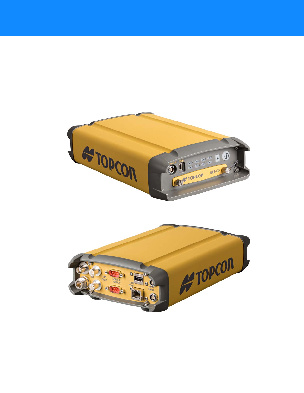
The Net-G5 is a multi-frequency, GNSS receiver built to be the most advanced and convenient network reference
receiver . The integr ated receiver design includes a GNSS receiver board based on Vanguar d™ technology , industry
leading Fence Antenna™, internal long-life batteries, memory storage, and optional cellular wireless
communication technology. The Net-G5 delivers world-class positioning and navigation capability to your
application by tracking signals from multi-constellation satellite systems, including GPS, GLONASS, SBAS, BeiDou,
and Galileo.
The Net-G5 can receive and process mult iple signal types (including the latest GPS L2C, L5, GLONASS C/A L2, and
GALILEO
conditions.
1
signals) improving the accuracy and reliability of the solution, especially under difficult job-site
Figure 1: Net-G5 Receiver - Front
Figure 2: Net-G5 Receiver - Back
Introduction
1. Contact Topcon Technical Support for detailed information about the supported GALILEO signals.
P/N: 1004636-01
1
Page 10

Receiver Features
The following features combine to provide a positioning system efficient, secure, and appropriate for any survey
or application that requires highly-accurate timing and positioning solutions:
•
448 universal tracking channels
•
Multipath reduction
•
Adjustable phase locked loop (PLL) and delay lock loop (DLL) parameters
•
1PPS and event marker
•
External oscillator input
•
GNSS-disciplined internal crystal oscillator output
•
RS232C and USB port connectivity
•
USB storage device
•
Removable memory
•
Backup battery system
•
Ethernet connectivity
•
Web-based management
•
Satellite Based Augmentation Systems (WAAS, EGNOS, etc.)
•
Dual- or multi-frequency modes, including static, kinematic, real-time kinematic (RTK), and differential (DGPS)
survey modes.
•
Ntrip server/client
•
Multiple survey parameters, including multiple mask angl es, static and dynamic modes, auto data logging, etc.
Introduction
Unpacking Your Receiver Kit
This section describes the documentation, standard kit components, and accessories (depending on your
purchase) that accompany your receiver. When you unpack your receiver kit, verify you received the items listed
in this section. Make sure the items do not appear damaged from shipment. If any of the items are missing or
damaged, contact your Topcon dealer or Topcon technical support. See
Technical Documents
The
Net-G5 Operator’ s Manual
quickly and efficiently. You can download a digital copy of the
from the Topcon Total Care website at www.topconcare.com.
TopNET+ Operator’s Manual
remotely configure your new receiver.
Topcon Receiver Utility (TRU) Onl ine Help
“Using Topcon Software With Your Receiver”.
and
Reference Card
– An on-screen help document that contains detailed information on how to
– Help documentation for TRU is embedded in the software; See
are designed to help you set up and use your new receiver
Using Topcon Software With Your Receiver
TopNET+ software is a full-suite of GNSS R efer ence Network management tools that builds on TopNET RTK by
adding Network RTK (model solution) to the av ailable data services. It extends traditional RTK capabilities and
significantly improves initialization times when the Rover is a long distance from the nearest reference station.
The Topcon Receiver Utility (TRU) is hardware configur ation software for r eceivers and peripher al devices. You
can install it on personal computers and data controllers. You can download the TRU software from the Topcon
TotalCare website (www.topconcare.com). TRU
Contact your Topcon dealer for more information about the Topcon software described above.
Help
is only available on the software.
“Getting Technical Support” on page 3.
Net-G5 Operator’s Manual
and
Reference Card
Receiver Features
P/N: 1004636-01
2
Page 11

Getting Technical Support
Before contacting a Topcon customer representative about any problems with the receiver, see
“Troubleshooting” on page 37 for some solutions that may fix the issue.
Contact your local Topcon dealer or visit the Topcon Total Care Web site (www.topconcare.com) for technical
support.
For quick and effective support, provide a detailed description of the problem.
When contacting T opcon f or technical assistance, provide the following information for better and faster service:
1. A description of the following:
– Field operation that was being performed when the problem occurred
– Details of the unexpected behavior, symptoms, and any error messages that precede or follow the
problem
– Problem occurrence frequency or patterns
2. Receiver information and configuration settings. For receiver information, click Information in TRU,
select Save to File, enter a file name, and save it to the computer.
3. Specifications of mobile devices and computers used in the field or office exhibiting the problem. These
specifications should include model information, version number, operating system information, memory
and storage capacity, etc.
4. Information about the system software, including the version number and steps to reproduce the problem.
5. A description of the field environment and/or observation conditions when the problem occurred.
Introduction
Website
The Topcon webs ite provides current information about Topcon’s line of products. The support area of the
website provides access to Topcon field and office software, manuals, frequently asked questions, and so forth.
To access the Topcon website, visit www.topconpositioning.com.
The Topcon’s TotalCare website also provides complete support, such as news, updates, reminders, training,
live Webinars, and customer service to help you get the information you need. Visit www.topconcare.com.
Getting Technical Support
P/N: 1004636-01
3
Page 12
• • • • • •
Getting Acquainted
1
2
3
4
5
6
7
The Net-G5 receiver enclosure is fully sealed and incorporates the GNSS receiver board, antenna, internal
batteries, memory storage, and wireless communication devices. A flexible user interface enables y ou to connect
the receiver with various external devices, such as computers, network devices, sensors, frequency sources, etc.
Receiver Housing Overview
The receiver’s standard hardware configuration includes:
•
three serial data ports
•
a USB device and USB host ports
•
an Ethernet port
•
an interface for controlling and viewing data
logging, link, and power status
•
an SD card slot
•
a SIM card slot
Although this is the standard configuration, the OAF must enable some of these features for proper operation.
See
“About the OAF” on page 24 for details.
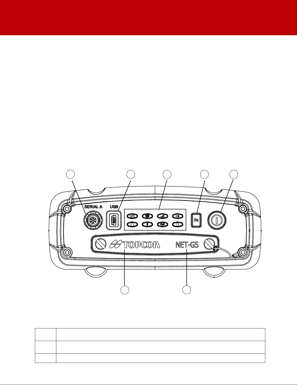
Front Panel View
•
an external GNSS antenna port
•
a frequency input/output port
•
a 1PPS port
•
Event Marker port
•
two internal batteries
•
two power ports
1
2
3
Getting Acquainted
Figure 3: Receiver – Front Panel View
• Serial Port A (7-Pin ODU-MINI-SNAP) – Used for communication between the receiver and an external
device.
• Mini USB – Used for high-speed data transfer and communication between the receiver and an external
device.
• LED Display Panel – For LED descriptions, see “Display Panel” on page 9.
Table 1. Font Panel Ports
P/N: 1004636-01
4
Page 13
• FN Button – Turns data recording on and off.
1
2
3
4
8
7
6
5
4
• Power Button – Turns the receiver on and off; puts the unit in Sleep mode.
5
• SIM Card Slot – Resides on the front panel under the door and connects the SIM card to the receiver
6
7
board to provide cellular connectivity.
• SD Card Slot – Resides on the front panel under the door and connects the SD car d to the receiver boar d
to provide memory.
Back Panel View
Table 1. Font Panel Ports
Getting Acquainted
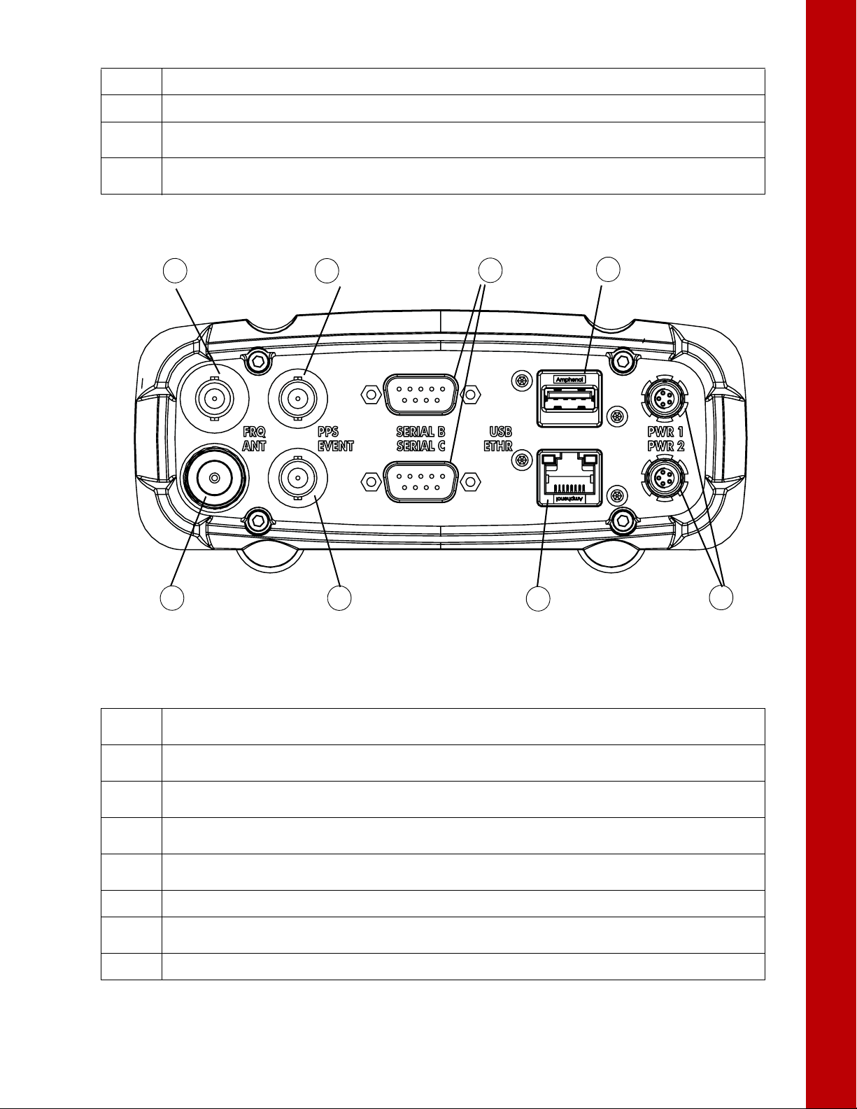
Figure 4: Receiver – Back Panel View
Table 2. Back Panel Ports
• External Frequency Port (BNC Connector) – Used for an external frequency input or the r eceiver’s internal
1
2
3
4
5
6
7
8
frequency output.
• PPS Port (BNC Connector) – Used for generating one pulse per second signals with programmable
reference time, period, and offset. The pulse is synchronized to a specified reference time.
• Serial Ports (x3) – Used for communication between the receiver and an external device.
Ports A and B are RS-232. Port C is RS-422.
• USB Type A – Used for high-speed data transfer and communication between the receiver and an
external device.
• Power Ports (x2) – Connects the receiver to external power sources. PWR1 supplies power to receiver
and charges internal backup battery. PWR2 does not charge the batteries.
• Ethernet – Used to connect the receiver to a computer or network.
• Event Marker Port (BNC Connector) – Used to input an event synchronized with a specified time
reference.
• GNSS Antenna Port (Type N Connector) – Used for detecting GNSS signals.
Receiver Housing Overview
P/N: 1004636-01
5
Page 14
Cables and Power Supply
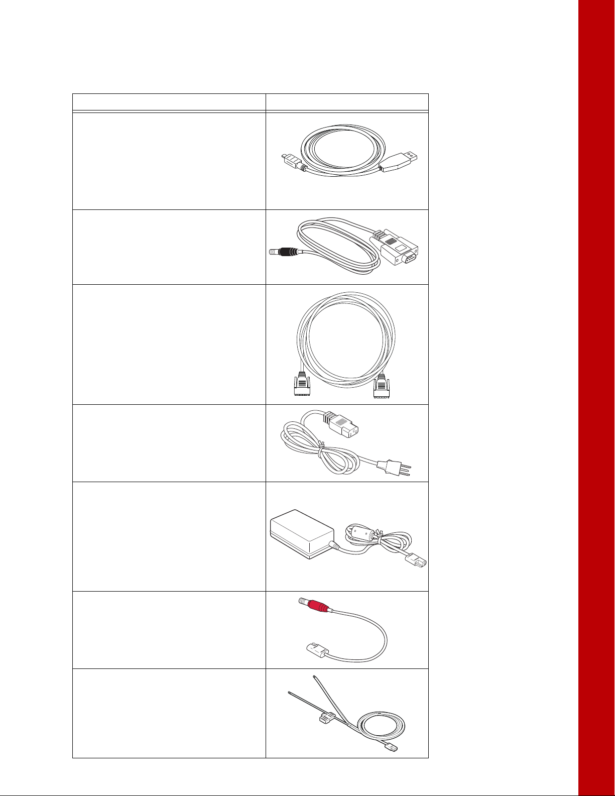
The Net-G5 package includes standard communication and power cables. Table 3 lists these cables.
Table 3. Receiver Package Cables
Cable Description Cable Illustration
USB Cable
Connects the receiver to an external device
(controller or computer) for high-speed data
transfer and receiver configuration.
p/n 14-008081-01
This can also be purchased at any local
computer store, and must be high speed
certified.
Serial Cable
Connects the receiver to an external device
(controller or computer) for data transfer and
receiver configuration. Body of connector is
black.
p/n 14-008005-03
Null Modem Cable
Connects the receiver with an external device
(controller or computer) for data transfer and
receiver configuration.
p/n 14-008086-01
Can also be purchased at any local computer
store.
Getting Acquainted
Power Cable
Connects the power supply unit to a grounded
outlet.
U.S. p/n 1005793-01
Europe p/n 1005794-01
Power Supply Unit
Converts the alternating current (AC) supplied
from an electrical outlet to a direct current
(DC) for powering the receiver.
The unit connects to the receiver via the
receiver power cable (see the power related
sections in “Using External Power Sources” on
page 13).
p/n 1005555-01
Receiver Power Cable
Connects the receiver and the power supply
unit via SAE connectors. Body of connector is
red.
p/n 14-008016-04LF
Fused Pigtail Cable
Connects the receiver power cable via SAE
connectors with a custom power supply unit
via bare wires.
p/n 14-008099-01
Cables and Power Supply
P/N: 1004636-01
6
Page 15

SD Card (Memory)
The receiver is equipped with a removable memory SD card that provides up to 32 GB of data storage. As data
is logged to the memory card, the REC LED displays the memory capacity status. See
page 11 for more information.
Insert the SD Card into the SD card slot located on the front panel under the door. Once installed, the SD card
usually remains inside the receiver. You can access the data that resides on the card using the serial, USB,
Ethernet ports, or the Vanguard web interface.
Installing the SD Card
To preserve data integrity, only install or remove the card when the receiver is powered off.
1. Make sure the receiver is turned off.
2. Make sure the card has been formatted for the F AT32 file system before first use. See “Formatting the SD
Card” on page 7.
3. On the front panel, open the door by turning the two screws to the left.
4. Carefully insert the SD card, label side up, into the card slot as shown in Figure 5.
5. Make sure the bottom of the card is recessed before closing the receiver door.
Once the receiver is turned on, the receiver board detects the SD card and is ready for use.
Getting Acquainted
“Recording LED” on
Formatting the SD Card
The Net-G5 requires an external SD card format ted for the F A T32 file system. Y ou can format t he SD card using
the internal disk management application provided by Microsoft; however, this application cannot create
partitions larger than 32 GB. You can also format the card with PC running Windows, and then use the card in
the receiver.
For more information about FAT32 limitations and formatting, got to
http://support.microsoft.com/kb/184006/en-us. For partitions larger than 32 GB, use external disk partition
software.
Formatting the SD card permanently er ases all data on the card . Back up any necessary data bef ore formatting
the SD card.
SD Card (Memory)
Figure 5: Inserting an SD Card
P/N: 1004636-01
7
Page 16

Internal Batteries
The Net-G5 receiver was designed with internal, non-removable batteries, so there is no battery door or
connectors to worry about. These batteries, when fully are easily charged using the supplied power adapter or
an external power source. See
Getting Acquainted
“Internal Batteries” on page 14 for more information.
Internal Batteries
P/N: 1004636-01
8
Page 17
• • • • • •
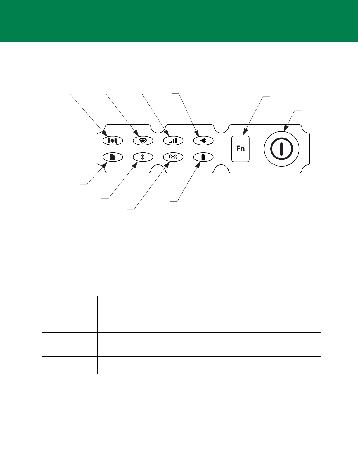
Display Panel
Status
(STAT )
Wi-Fi Cellular
(CELL)
Function
(FN)
Button
Power Button
Power
(PWR)
Recording
(REC)
Bluetooth
(BT)
Communication
(RxTx)
Battery
(BATT)
The Net-G5 receiver has a highly-visible display panel with single-button operation. The LED display panel enables
you to control receiver power and data recording. The LEDs display the status of the satellite tracking,
recording/memory capacity, wireless connections, and power. This chapter describes the different LED blink
patterns and what they mean.
Power Button
The power button performs multiple functions. The duration in which the button is pressed and held determines
how the receiver will perform. While pressing the button, the LED panel indicates the selected operation using
particular LEDs.
Figure 6: LED Display Panel
Table 4 describes how to use the power button.
Table 4. Power Button Features
FUNCTION PRESS BUTTON LED DESCRIPTION
Power On 1+ seconds LEDs blink green until the startup is complete. LEDs return to
normal and the Power LED is solid green, indicating that the
receiver is on.
Power Off 3-10 seconds All LEDs are off. Release the Power button when the Power LED is
Clear NVRAM See “Resetting the R eceiver (Clearing the NVRAM)” on page 30 for
solid red. When no external power is present, the Power LED is
dark.
more information.
Display Panel
P/N: 1004636-01
9
Page 18

Function Button
FUNCTION PRESS BUTTON LED DESCRIPTION
Power Off Press button No action.
Display Panel
Tabl e5.Function Button Features
RECEIVER IS OFF
RECEIVER IS ON
Start/Stop Data
Logging
Toggle PostProcessing Mode
Change Information
Mode
Change Baud Rate of
Serial Port
1-5 seconds • REC LED is green indicating data logging has started.
Less than 1 second • Press for less than 1 second when “Occupation mode switch”
Three times for less
than 3 seconds
5-8 seconds • After approximately 5 seconds, the REC LED becomes red.
Receiver Status LEDs
The status LEDs provide information about the battery life, tracked satellites, memory capacity, and wireless
connectivity. This section describes the color and behavior of each LED.
Tracking Status LED
The tracking status LED displays what type of satellite the receiver is tracking.
Table 6. Tracked Satellites
• REC LED blinks green each time data is written to the receiver’s
memory.
• REC LED is red when receiver is out of memory, has a hardware
problem, of contains an improper OAF.
has been enabled using TRU.
• Press three times for less than 3 seconds when “LED blink mode
switch” has been enabled using TRU.
Release the Function button during the next 3 seconds.
Color Description
Green GPS
Yellow GLONASS
Cyan Galileo
Blue SBAS/OMNI
Magenta BeiDou
White QZSS
Function Button
P/N: 1004636-01
10
Page 19
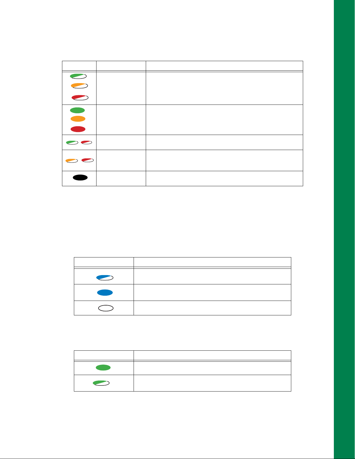
Recording LED
The memory LED indicates if data is being written to memory and displays how much memory the re ceiver has
available for recording.
Table 7. Recording LED Patterns
Display Function Description
Greater than 50%
Greater than 10%
Less than 10%
File logging is in progress. Each blink indicates data is being
written to memory . When the receiver is in dynamic mode, the LED
blinks twice every second. In static mode, the LED blinks once
every second.
Display Panel
Greater than 50%
Greater than 10%
Less than 10%
Missing or faulty
memory
The file is closed. A solid light indicates no data is being recorded.
Alternating green and red LEDs indicate all files are being deleted.
Alternating red and yellow LEDs indicate the memory card is being
initialized or formatted.
The LED is off.
Communication LEDs
The communication LEDs display the status of the wireless activity. The following tables describe the
communication activity for four use cases: Bluetooth, Wi-Fi, Cellular, and UHF.
Bluetooth Only Status
Tabl e8.Bluetooth LED Patterns
LED Color Description
Bluetooth is on. Waiting for a connection.
Wi-Fi LED
Receiver Status LEDs
A single Bluetooth connection is established.
Bluetooth is turned off.
Table 9. Wi-Fi LED Patterns
LED Color Description
The internal Wi-Fi modem is starting up.
The internal Wi-Fi modem is transmitting or receiving data.
P/N: 1004636-01
11
Page 20

Cellular Status
1
Table 10. Cellular LED Patterns
LED Color Description
The cellular modem is starting up.
The cellular modem is transmitting or receiving data.
Battery LED
The Battery LED indicates the remaining charge of the internal batteries. When an external power source is
utilized, the LED turns green and begins to blink if the batteries begin to charge. See
information.
Tabl e11.Battery LED Patterns
LED Color Description
THE RECEIVER IS ON; INTERNAL BATTERIES IN USE
The charge is greater than 50 percent.
The charge is greater than 10 percent.
The charge is less than 10 percent.
Table 11 for more
Display Panel
Power LED
LED Color Description
THE RECEIVER IS ON; EXTERNAL POWER IN USE; PWR LED IS SOLID GREEN
An external power source is in use, and the internal batteries are fully charged.
The internal batteries are at greater than 50% capacity; the batteries are being
charged.
The internal batteries are at greater than 15% capacity; the batteries are being
charged.
The internal batteries are at less than 15% capacity; the batteries are being charged.
THE RECEIVER IS OFF
The receiver is connected to an external power source, and the batteries are fully
charged.
The receiver is connected to an external power source, and the batteries are being
charged.
Tabl e12.Power LED Patterns
An external power source is in use and connected to the PWR1 bulkhead. The LED
blinks green at 1 Hz intervals.
An external power source is in use and connected to the PWR2 bulkhead. The LED
blinks green at 2 Hz intervals.
An external power source is in use and connected to the PWR1 and PWR 2 bulkheads.
1. Cellular modem functionality will be added in a later version of firmware.
Receiver Status LEDs
LED is dark when no external power source is connected.
P/N: 1004636-01
12
Page 21

• • • • • •
Managing Power
This chapter describes how to power the receiver, charge the internal batteries, and use an external power source.
Turning On/Off the Receiver
To turn on the receiver, press and hold the power button until the LEDs briefly flash. When the receiver is turned
on, the receiver’s channels initialize and begin tracking all visible satellites at any time and location.
To turn off the receiver, press and hold the power button for more than three and less than 10 seconds (release
the power button when the POWER LED blinks yellow). Allow the receiver to complete the power off cycle
(approximately 30 seconds).
The receiver will draw a small amount of power from the batteries when it is turned off. If the
receiver is placed in storage for a long period, such as a few months, the batteries may be come f ully
discharged. You will need to use an external power supply or recharge the batteries before use.
The Linux operating system will cause a brief dela y in t he po wering on and of f of the rece iver. When
powering off, the Power LED will briefly blink yellow before shutting down.
Using External Power Sources
The Net-G5 receiver is designed to draw power from external power sources before drawing power from the
internal backup batteries.
You can connect the receiver to an external power source, such as a vehicle battery , with 9 V to 28 VDC to operate
the receiver. When setting up the receiver, consider the following powering requirements:
•
Never use an extension cord for permanent power supply. This setup can create a fire hazard.
•
Always use a grounded outlet.
•
Use a surge protector to protect connected electronic devices.
See “General Details” on page 42 for more information on external power source requirements to power the
receiver and charge the internal batteries.
Power input greater than 28 VDC could damage the receiver.
Powering the Receiver
The receiver has two power ports. PWR2 will not charge the batters.
To power on the receiver:
1. Connect the power cable to the power supply unit.
2. Connect the SAE connectors on the power adapter cable and power supply unit.
3. Connect the power adapter cable to the PWR port on the receiver’s rear panel.
Managing Power
P/N: 1004636-01
13
Page 22

4. Plug the power supply into an available outlet.
Figure 7: Connect the Receiver to a Power Source
Checking Power Status
You can ch eck the receiver’s power status using the PWR LEDs or available Topcon software. The power LEDs
on the receiver indicate the following power status:
•
Solid Green – power within the acceptable range (6–28 V DC) is present on both PWR1 and PWR2 ports and
is being used to power the receiver.
•
Solid Red – either a power failure has occurred with a connected power source or the port is not receiving
power. For details, see
•
Green blinks – power within the acceptable range (6–28 V DC) is present on this PWR port and is being used
to power the receiver and to charge the corresponding battery.
•
Red blinks – the corresponding backup battery is being charged.
•
Off – the receiver consumes power from internal backup batteries or the receiver is turned off.
Refer to the TopNET+ software manual for details on checking the power status via installed software.
Managing Power
“Insufficient Power” on page 15 and “Powering Problems” on page 37.
Internal Batteries
The receiver first draws power from a connected external power source. When there is no valid external power
source connected or if the source has discharged lower than 6.5V, the receiver will draw its power from highcapacity internal batteries (non-removable). Depending on the use case, the hours of operation provided by the
internal batteries vary.
Checking Power Status
P/N: 1004636-01
14
Page 23

Charging the Backup Batteries
When the battery charge is low, the BAT LED changes from solid green to yellow and then red, depending on
the remaining charge (see
source, the batteries begin to charge whether the receiver is turned on or off.
To charge the batteries:
1. Connect the supplied power cable to the receiver’s power port.
2. Connect the power cable SAE connector to the SAE connector of the power adapter.
3. Plug the power adapter into an available outlet to fully charge the batteries. The batteries charge
simultaneously. You cannot over charge the batteries; the batteries stop charging when they are full.)
The BAT LED blinks as the batteries charge.
Use a grounded wall outlet or grounded surge protector while charging. The socket should be
located near the equipment and easily accessible.
The backup batteries charge when the input voltage is between +9 and +28 V DC.
“Battery LED” on page 12). When the receiver is connected to an external power
Insufficient Power
Managing Power
If the batteries become fully discharged and an external power supply is not connected, the receiver will shut
down and automatically save recorded files. To avoid disruptions, check the BAT LED on the display panel for
the battery charge status. See
If the receiver shuts down due to insufficient power, the receiver and all communication ports become
deactivated.
To restore power to your receiver and turn it back on:
•
Recharge the batteries.
•
Make sure the power/serial cable is correctly connected to the receiver’s port.
– Align the keyways when connecting the power/serial cable to the receiver port.
– Turn the cable lock clockwise until it clicks to secure the cable in place.
– To disconnect the cable, turn the lock counter-clockwise, and then gently remove the cable.
•
Connect the receiver to a different power source.
Power supplied to the receiver should match the specifications provided by Topcon on the product.
Failure to comply with these specifications may damage the receiver.
“Battery LED” on page 12 for more information.
Charging the Backup Batteries
P/N: 1004636-01
15
Page 24

• • • • • •
Configuring the Receiver
The Net-G5 receiver is intended primarily for use as a permanent or semi-permanent GNS S Reference Station to
establish networks supporting both real-time and post-processing applications. You can stream observation data
through any port to any device capable of receiving and utilizing it, including T opNET+ reference station softw are.
You can also log data internally to removable SD cards for downloading to support static or kinematic surveying,
mapping, monitoring, and positioning applications.
The Net-G5 is configurable for single to multiple scenarios, including the following:
•
permanent and semi-permanent Reference Station
•
temporary campaign receiver
•
RTK or DGPS rover (for monitoring a fixed location, system monitoring, or mobile data collecting)
The sections in this chapter describe receiver configuration, receiver options, loading a new Option Authorization
File (OAF), updating firmware, and performing a factory reset. To do this, you will need to download the Topcon
Receiver Utility (TRU) software from the Topcon Total Care website at www.topconcare.com. For information
about installing the software, see the
Configuring the Receiver
The Net-G5 is generally configured as a static R eference Station that collects GNSS measurement inf ormation and
logs the data to a removable SD card, streams the data to a central computer, and possibly connects directly to
one or more radios (or any combination of these configurations). The T opcon Receiver Utility (TRU) and TopNET+
software are used to manage and configure the various functions of the r eceiver. Configuration settings are saved
to the NVRAM of the GNSS receiver board and are reflected when using the LED display panel.
The full range of both TRU and TopNET+ configuration and operation are outside the scope of this manual. For
more information on any of the procedures in this section, or on TRU or TopNET+, refer to the appropriate manual
available from www.topconcare.com, or embedded in TRU.
Once you have established a connection between the receiver and the computer, you will be able to:
Topcon Receiver Utility (TRU) Online Help
, available only in the software.
•
configure the receiver and its components
•
send commands to the receiver
•
download files from the receiver’s memory
•
load a new OAF and other configuration files to a receiver
Using the Web Interface
The Net-G5 includes a built-in W eb server that allows you to configure and monitor the receiver via a W eb browser .
The following Web browsers are recommended for accessing the receiver:
•
Windows Internet Explorer 6.0 or later
•
Google Chrome
•
Mozilla Firefox 2.0 or later
•
Opera 9.0 or later
Accessing the Receiver Through the Web Browser
Before accessing the Net-G5 using the Web browser, determine whether the valid network par ameters (IP address,
gateway, etc.) are specified in the receiver. Refer to the
parameters.
1. Open a recommended Web browser.
The browser window appears.
2. In the Address or Location bar of the Web browser, type one of the following addresses:
http://ipaddress<:port number> or
https://ipaddress<:port number>
TRU Online Help
for details regarding the network
(if SSL is enabled).
Configuring the Receiver
P/N: 1004636-01
16
Page 25

The
ipaddress
is the receiver’s IP address;
port number
is the port number you should specify if set to a number
other than the default port number (port 80 for HTTP, and port 443 for HTTPS).
Once the information is entered, the main page displays.
Configuring the Receiver
Figure 8: Vanguard Web Interface – Main Page
When accessing the Web interface via SSL communications, a warning may appear stating the
security certificate was issued by a company you have not chosen t o trust. You can safely ignore this
warning and continue with the login procedure. Your communications will use SSL.
3. Enter the login name and password to access the Web interface.
The default login and password are
admin
. Login names and passwords are case sensitive, and can be up
to 12 alphanumeric characters.
Figure 9: Vanguard Web Interface – Login
4. Click LOGIN.
After logging in to the Web interface, you can view and modify the receiver parameters.
You can access the receiver without entering the login name and password; however, you will be
restricted to view-only activities.
Configuring the Receiver
P/N: 1004636-01
17
Page 26

Net-G5 Web Interface Ports
Although not necessary for functionality, you can configure the following ports to use with the Net-G5 Web
interface.
•
TCP 80 - HTTP
•
TCP 8888 - web socket
•
TCP 21 - FTP
•
TCP 23 - Telnet
•
TCP 8002 - GRIL port
If you are accessing the Web interface from behind a firewall or router, open and forward each port to the
receiver’s IP address.
Viewing Receiver Information
In the Topcon Receiver Utility (TRU), the Receiver Info window displays basic Receiver information, such as
hardware and firmware versio ns, RAM size, receiver ID, serial number, etc.
To open the Receiver Info window:
1. Connect the receiver to a computer and open TRU.
2. In TRU, connect to the receiver.
3. Click DeviceApplication ModeReceiver Managing.
4. Click DeviceConnect.
5. In the Connection Parameters window, select the correct serial port, and click Connect.
6. In the TRU main window, click the Information icon. The Receiver Info window (Figure 10) appears.
Configuring the Receiver
Viewing Receiver Information
Figure 10: TRU – Receiver Info
P/N: 1004636-01
18
Page 27

Updating Firmware
Update Firmware Using TRU
The following describes how to update firmware on the Net -G5 using a network connection. Y ou can also update
the firmware using a Bluetooth, USB or a serial connection. To connect the receiver with a computer using a
USB connection, you will need to install a USB driver. USB drivers and firmware are available at
www.topconcare.com.
Receiver board firmware is released as a compressed *.tar file uploaded using TRU, TopNET+, or FTP.
Connect to the Receiver
1. In TRU, click DeviceApplication ModeReceiver Managing.
2. Click DeviceConnect. The Connection Parameters screen appears.
3. Select Network from the Connect Using drop-down list, then click the dialog button from Device
Name (
Figure 11
Configuring the Receiver
). The Select Network Device screen appears.
Updating Firmware
Figure 11: Connect to the Device Using Your Network
P/N: 1004636-01
19
Page 28

4. Right-click in the Select Network Device screen, and click Add (Figure 12). The Network Connection
screen appears.
Figure 12: Select Add to Add a Device
5. Enter the appropriate information for Friendly Name, IP Address or Host Name, TCP Port, and
Password, then click OK (
Figure 13). The Select Network Device screen appears.
Configuring the Receiver
6. Click OK on the Select Network Device screen. The Connection Parameters screen appears.
Updating Firmware
Figure 13: Enter the Information for the Device
P/N: 1004636-01
20
Page 29

7. Click Connect (Figure 14).
Figure 14: Connect to the Device
Load the Firmware
1. In TRU, click File Explorer. The File Explorer screen appears.
2. Click the Files tab.
3. Right-click in the File Explorer screen, and click Open in Windows ExplorerSD Card (Figure 15). An
instance of Windows Explorer will open.
Configuring the Receiver
Updating Firmware
Figure 15: Open the SD Card in Windows Explorer
P/N: 1004636-01
21
Page 30

4. Op e n the b310.update folder in Windows Explorer, and delete any content in the folder (Figure 16).
Figure 16: Delete the Contents from the b310.update folder
5. Open another instance of Windows Explorer and locate the appropriate *.tar file (Figure 17).
Configuring the Receiver
6. Drag the *.tar file into the b310.update folder, and close both Windows Explorer windows.
7. Click OK in the TRU File Explorer screen. The TRU main screen appears.
8. Click Terminal. The Terminal screen appears.
Updating Firmware
Figure 17: Locate the Firmware File
P/N: 1004636-01
22
Page 31

9. Enter
During installation, the Power LED will blink yellow-green. After installation, the P ower LED will be solid green.
Once the Power LED is solid green, close the Terminal screen and click Device
%%set,update,yes
in the command prompt, and click Send (Figure 18).
Figure 18: Send the Update Command
Disconnect in TRU.
Configuring the Receiver
Verify Firmware Upload
1. In TRU, click DeviceConnect. The Connection Parameters screen appears.
2. Click Connect. The TRU main screen appears.
3. Click Information. The Receiver Info screen appears showing the current firmware loaded to the
device (
Figure 19).
Updating Firmware
Figure 19: Receiver Info Displays the Current Firmware
P/N: 1004636-01
23
Page 32

Update Firmware Using an SD Card
Install Firmware Installation File
The following process can be done by removing the SD card from the receiver, or connecting to it using FTP,
TRU, or TopNet+.
1. Connect to the receiver or remove the SD card, and insert it into a computer.
2. Locate and open the b310 sub-folder on the SD card.
3. Verify that a b310.update folder is present. If not, create the folder.
4. Locate and copy your *.tar firmware installation file to the b310.update folder.
5. If you removed the SD card from the receiver in Step 1, insert the card into the receiver. Otherwise,
disconnect from the receiver.
Begin Firmware Update
Configuring the Receiver
Open the GRIL terminal and send the command
complete. During installation, the Power LED will blink yellow-green. After installation, the Power LED will be
solid green. Once the Power LED is solid green, connect to the receiver using TRU and verify that the correct
firmware is installed (see
About the OAF
Topcon issues an Option Authorization File (OAF) to enable the specific options that you purchased. Topcon’s
OAF system allows you to customize and configure the receiver according to your particular needs, therefore
purchasing only the options you require.
The Net-G5 receiver typically ships with an OAF as per initial purchase of the receiver kit configuration. There
are several upgrade options available with the receiver that can extend the receiver’s func tionality to better suit
your job requirement. Examples of upgrade options are listed below:
•
Standard Options
•
GPS
•
GLONASS
•
GPS + GLONASS dual frequency static operation
•
GALILEO
•
BeiDou
•
QZSS
•
50HZ
•
100HZ
•
Additional external frequencies
Contact your Topcon dealer or a representative for a complete listing of available options and pricing
information.
%%set,update,yes
“Verify Firmware Upload” on page 23).
. The update will take up to 10 minutes to
About the OAF
P/N: 1004636-01
24
Page 33

Checking the Receiver’s OAF
To use TRU to view the status of the receiver’s options:
1. Connect the receiver to a computer and open TRU. See the
more information about connecting the receiver to a computer.
2. In TRU, connect to the receiver.
3. Click the Options icon in the main window. The Receiver Options window (Figure 20) displays, so
you can view the current authorization options and upload new ones.
Topcon Receiver Utility (TRU) Online Help
for
Configuring the Receiver
Figure 20: Receiver Options
You can also check the receiver’s OAF using TopNET+ or the Vanguard web interface.
About the OAF
P/N: 1004636-01
25
Page 34

Loading an OAF
Topco n dealers provide customers with OAF files. For any OAF related questions, e-mail Topcon at
options@topcon.com and include the receiver’s ID and serial number. To obtain these numbers, see
Receiver Information” on page 18.
To load a new OAF:
1. Follow the steps in “Checking the Receiver’s OAF” on page 25.
2. Right-click on the Receiver Options window, and select Upload OAF.(see Figure 21).
Configuring the Receiver
“Viewing
Figure 21: Right-click and Select Upload OAF
3. Navigate to the loc ation of the new Option Authorization File.
4. Select the appropriate file, and click Open (Figure 22).
About the OAF
Figure 22: Load OAF
P/N: 1004636-01
26
Page 35

Topcon’s TRU initially checks to see if the selected file is compatible with the currently connected receiver. If
you chose a file not intended for this receiver, the Upload OAF window displays an error icon next to the
Receiver ID and disables the Upload the File to the Receiver button.
5. Click Upload the File to the Receiver to start loading the file (Figure 23).
Configuring the Receiver
Figure 23: Upload the OAF to the Receiver
6. Click Yes at the prompt to reset the receiver (Figure 24).
Figure 24: Reset Receiver
When the receiver resets, the Connection Parameters window opens.
About the OAF
P/N: 1004636-01
27
Page 36

7. Click Connect (Figure 25). The TRU main window appears.
Figure 25: Connect to the Receiver
Configuring the Receiver
8. Click Options (Figure 26). The Receiver Options window displays.
Figure 26: Click Options
About the OAF
P/N: 1004636-01
28
Page 37

In the Receiver Options window ( Figure 27), ensure the following are correct:
•
If you uploaded a universal OAF, make sure the expiration date is still valid.
•
If you uploaded a customer OAF, make sure the correct customer file is loaded.
Configuring the Receiver
Figure 27: Receiver Options Window
To view additional OAF details , right-click in the Receiver Options window and select ViewDetails
(
Figure 28).
About the OAF
Figure 28: Additional OAF Details
P/N: 1004636-01
29
Page 38

Resetting the Receiver (Clearing the NVRAM)
The receiver’s Non- V olatile Random Access Memory (NVRAM) holds data requir ed for satellite tr acking, such as
ephemeris data and receiver position. The NVRAM also keeps the current receiver’s settings, elevation masks,
recording interval, and information about the receiver’s internal file system. Clearing the receiver’s NVRAM
resets the receiver and restores the factory default settings.
Although performing a “factory reset” of the receiv er is not recommended as a common practice, there are times
when it can eliminate communication or tracking problems.
After performing a reset, the receiver requires time to collect new ephemerides and almanacs (around 15
minutes).
Resetting the receiver will not delete any files already recorded in the receiver’s memory , and the NVRAM keeps
information about the receiver file system.
To clear the NVRAM:
1. Power off the receiver.
2. Press and hold the Function button.
3. Press and release the Power button for one second.
4. Verify that the Tracking Status LED is solid green.
5. When the Tracking Status LED blinks orange, release the Function button.
You can also use TRU to clear the NVRAM:
1. Connect the receiver to a computer, and open TRU. See the
more information about connecting the receiver to a computer.
2. In TRU, connect to the receiver.
Topcon Receiver Utility (TRU) Online Help
Configuring the Receiver
for
3. Click the Tools icon in the main window.
The Tools window appears, enabling you to reset the receiver and clear the NVRAM.
Figure 29: Tools Dialog Box
4. Click Factory Reset, and then click Yes to continue.
Resetting the Receiver (Clearing the NVRAM)
P/N: 1004636-01
30
Page 39

• • • • • •
System Setup
For a typical permanent or semi-permanent R eference Station setup, place the Net -G5 receiver in a secure location
with access to power and communication links as required. Survey the antenna lo cation v ery ac cur at ely, making
sure the receiver is free of signal obstructions and interference (RF, multipath, etc.).
As a temporary Reference Station, certain steps must be performed to ensure pr oper data collection. The following
steps detail the use of the Net-G5 in a temporary Reference Station setup.
Before logging data, make sure the receiver contains current almanac and current ephemeris data.
Step 1: Setting Up the Receiver
1. Place the receiver in the predetermined location. A sturdy shelf or out-of-the-way table may be a con venient
spot.
2. For a permanent mount, drill four screws through the mounting location (shelf) and into the receiver’s
mounting holes.
3. Connect the power cable to an available and grounded outlet. See “Powering the Receiver” on page 13 for
more details and precautions.
4. Connect the antenna cable. If recording data to an external device, such as a USB hard drive, connect it to
the receiver using the required communication cable.
System Setup
Figure 30: Mount Receiver and Connect Cables
P/N: 1004636-01
31
Page 40

Step 2: Measure Antenna Height
Reference Surface for
Oset Measurements
The location of the antenna relative to the point be ing measured is very important f or both surveys in which the
elevation of the point is important and in surveys for horizontal lo cation only . Horiz ontal surveys are often larger
in area than can reliably fit on a flat plane; therefore, the antenna adjustment must be done in three dimensions
and then projected onto a two dimensional plane.
The receiver calculates the coordinates of the antenna’s phase center. To determine the coordinates of the
station marker, the user must specify the following:
•
Measured height of the antenna above the station marker
•
Method of measuring the antenna height
•
Model of the antenna used
Antennas have two types of measurements:
•
Vertical – measured from the marker to the antenna reference point (ARP) located on the bottom of the
antenna at the base of the mounting threads.
•
Slant – measured from the marker to the lower edge of the antenna slant height measure mark (SHMM).
The point to which all measurements are being referenced is called the Phase Center of the antenna. This is
analogous to the point at which a distance meter measures in a prism. A user must enter the prism offset to
compensate for this point not being at a physical surface of the prism. For a GNSS antenna, the off set is entered
depending on the type of measurement taken.
•
For vertical, the offset is simply added to the measur ed vertical height to produce a “true” vertical height.
•
For slant height, the vertical height must first be calculated using the radius of the antenna, then the offset
can be added.
The offsets are different because of the difference in location between the slant measuring point and the v ertical
measuring point.
1. Measure the antenna height above the control point or marker, either the slant height or the vertical height
(
Figure 31).
2. Record the antenna height, point name, and start time in the field notes.
The height of the antenna and it’s offsets depend on the type of antenna used. Refer to the antenna’s
documentation for details.
System Setup
Refer to the antenna’s offset measurements card for measurement and offset details.
Figure 31: Measure Antenna Height – Example
Step 2: Measure Antenna Height
P/N: 1004636-01
32
Page 41

Step 3: Collecting Data
See the remaining sections in this chapter for more information about collecting data.
1. Turn on the receiver. The STAT (status) light LED blinks red at first.
•
Once the receiver has locked on to one or more satellites, the ST A T LED will blink green for GPS satellites and
orange fo r GLONASS s atellites. Other sat ellites will have different colors; see
for more information.
•
A short red blink indicates that the receiver has not solved a position. Four or more satellites provide optimal
positioning.
•
Once the short red blink is gone, the receiver has a position and surveying can begin; wait for green and
orange lights before beginning data collection. This ensures that the receiver has the correct date and time
and is locked on to enough satellites to ensure good quality data.
•
The process of locking on to satellites normally takes less than one minute. In a new area or after resetting
the receiver, it may take several minutes.
2. Press and hold the FN key for 1-5 seconds to begin collecting data.
3. Release the FN key when the REC (recording) LED turns green. This indicates that a file has opened and
data collection has started. The REC LED blinks each time data is saved to the memory.
System Setup
“T racking Status LED” on page 10
To configure data logging, see “Display Panel” on page 9 or refer to the
Step 4: Stop Data Logging
Stop logging data when you need to move the receiver, download data, or perform maintenance functions.
1. Press and hold the FN key until the REC LED light goes out.
2. To turn off the receiver, press and hold the power button for more than three and less than 10 seconds
(release the power button when the POWER LED blinks yellow). Allow the receiver to complete the power
off cycle (approximately 30 seconds).
Static Surveying for Reference Stations
Static surveying is the classic survey method, well suited for all kinds of base station surveys. One receiver over
a survey marker collects raw data during a certain period of time. The length of the observation sessions can
vary from a few minutes to several hours. The optimal observation session length depends on the surveyor’s
experience as well as the following factors:
•
the number of satellites in view
•
the satellite geometry (DOP)
•
the antenna’s location
•
the ionospheric activity level
•
the types of receivers used
•
the accuracy requirements
•
the baseline length
Generally , single-frequency receivers are used for baselines with lengths that do not exceed 15 kilometers (9.32
miles). For baselines of 15 kilometers or greater, use dual-frequency receivers.
Dual-frequency receivers have two major benefits. First, dual-frequency receivers can estimate and remove
almost all ionospheric effect from the code and carrier phase measurements, providing much greater accuracy
than single-frequenc y receivers over long baselines or during ionospheric storms. Secondly, dual-frequency
receivers need far less observation time to reach the desired accuracy requirement.
After the survey completes, data the receivers collect can be downloaded onto a computer and processed using
post-processing software (for example, Topcon Tools).
TRU Online Help.
Step 3: Collecting Data
P/N: 1004636-01
33
Page 42

Analyzing Signal-to-Noise Ratio
Knowing the strength and reliability of the ranging signal transmit ted from the satellites will help determine the
quality of the satellite signals. Use
Table 6-1. Typical SNR Values
Table 6-1 to help estimate signal quality from a satellite vehicle.
System Setup
SVa Elevation
(degrees)
10–20 >35 >10 >10
20–40 >40 >20 >20
40–60 >45 >30 >30
60–90 >50 >40 >40
a. SV = satellite vehicle
If the SNR value of a satellite signal is less than the threshold value from the table, then pay close att ention to
this satellite because it can potentially cause problems for getting accurate timing and positioning results.
C/A channel
(dB*Hz)
P1 channel
(dB*Hz)
Collecting Almanacs and Ephemerides
Each satellite broadcasts a navigation message that includes the ephemeris parameters of the satellite, the
almanac, and various other information. The ephemeris parameters describe the orbital motion of the satellite
and are used to predict its location/trajectory. The almanac gives the approximate orbit (course) for the
transmitting satellite and all other satellites in the same system only.
•
GPS and GLONA SS satellites broa dc a s t ep he meris data cyclically within 30 seconds.
•
GPS satellites broadcast almanac data cyclically within 12.5 minutes; GLONASS satellites broadcast almanac
data cyclically within 2.5 minutes.
When the receiver has an almanac, you can considerably reduce the time needed to search for and lock onto
satellite signals.
The receiver regularly updates the almanac and ephemerides and stores the most recent versions in its NonVolatile Random Access Memory (NVRAM).
P2 channel
(dB*Hz)
You need to collect or update the almanac and ephemerides under the following circumstances:
•
If the receiver has been off for a long time.
•
If the last known receiver position, stored in the NVRAM, is different from the present position by several
hundred kilometers.
•
After loading a new OAF.
•
After loading new firmware.
•
After clearing the NVRAM.
To collect almanacs and ephemerides:
1. Set up th e receiver.
The external antenna should be in a location with a clear view of the sky.
2. Turn on the receiver.
3. Wait for about 15 minutes while the receiver collects complete almanac and ephemeris data from the
satellites.
If 15 minutes have passed and the receiver does not lock onto satellites, then clear the NVRAM. See
“Resetting the Receiver (Clearing the NVRAM)” on page 30 for details.
Analyzing Signal-to-Noise Ratio
P/N: 1004636-01
34
Page 43

• • • • • •
Collecting Data
This chapter provides general information about recording data, downloading it, and removing files to free up
internal memory.
Setting Recording Parameters
The T opcon Receiver Utility (TRU) software enables you to set logging parameters, such as logging r ate and types
of messages, in which to record data. See the
in the software. Additionally, you can use TopNET+ or the Vanguard web Interface.
The Net-G5 is also compatible with any Topcon field software for configuration and recording raw data.
Using the Vanguard Web Interface
The Net-G5 includes a built-in W eb server that allows you to configure and monitor the receiver via a W eb browser .
the following Web browsers are recommended for accessing the receiver:
•
Windows Internet Explorer 6.0 or later
•
Google Chrome
•
Mozilla Firefox 2.0 or later
•
Opera 9.0 or later
The built-in Web server and
TRU Online Help
for more information. TRU
Help
is only available
Logging Rates
The receiver provides up to 32 GB of file space on the internal (non-removable) memory card. The amount of
memory used to log data depends on the logging rate. For more information about setting logging rate
parameters, see the
Recording Data
You can log raw GNSS data to the receiver’s internal memory and use the Topcon Receiver Utility (TRU) or
TopNET + software to download the files to a computer.
To start or stop recording data to the receiver, you can use the LED display panel or TRU:
1. Press the Power button to turn on the receiver.
2. Wait for the STAT LED to indicate satellites are being tracked. The STAT LED blinks green for GPS satellites
and amber for GLONASS satellites. A short red blink indicates the receiver has not solved a position. Five or
more satellites provide optimal positioning.
3. Press the Function button for one to five seconds to begin recording. You can also select File
Explorer
4. Make sure the REC light is blinking green. This indicates that a file has opened and data collection has
started. The REC LED blinks each time data is saved to the internal memory.
5. When you have finished recording, press the POWER button three times within two seconds, and make sure
the REC LED is dark. You can also select File Explorer
6. To turn off the receiver, press and hold the POWER button for 3 to 10 seconds until all LEDs turn dark and
the BAT LED is solid red.
LogsStart in TRU to begin recording data.
TRU Online Help
, which is embedded in the software.
LogsStop in TRU to end data recording.
Collecting Data
You can also log data using MAGNET Field software.
P/N: 1004636-01
35
Page 44

Managing Files
Raw data is recorded as time-tagged measurements in a single raw data file. Each file is recorded to the
receiver’s internal memory, and automatically given a name and a *.tps file extension. Yo u can then tr ansf er a
file of collected data to a computer with file managing software, such as the T opcon Receiver Utility (TRU). This
program allows you to use an automatic naming feature, enter file names, and delete files as necessary. For
more information, see the
TRU Online Help,
Downloading and Deleting Files
You can download data files to a computer or a controll er for storage, post -processing, or backup. The memory
card holds a finite amount of files, so you will want to delete files to restore memory capacity.
When the memory card is full, the receiver stops logging data, and the REC LED turns dark/off, indicating an
error condition. Existing data is not overwritten, unless you have the AFRM mode enabled.
T o delete ra w data files from the receiver, use a USB, serial, Wi-Fi, or Bluetooth connection to download the files
to a computer. In TRU, you can select the files you want to delete from the receiver. See the
Manual
Once a connection is established, you can download all or some files to a computer or controller and then use
the File Explorer feature in the Topcon Receiver Utility (TRU) to manage the raw data files. For more information
about using TRU to download or delete files, see the
available in the software.
If you use the Net-G5 as a refere nce station in a network, yo u can use TopNet+ or the Vanguard web interface
for downloading files.
for more information or TRU
Help
which is available in the TRU software.
, which is available on the software.
Topcon Receiver Utility (TRU) Online Help
Collecting Data
TRU Reference
, which is
Managing Files
P/N: 1004636-01
36
Page 45

• • • • • •
Troubleshooting
This chapter will help you diagnose and solve some common problems that may occur with the receiver.
Do not attempt to repair equipment yourself. Doing so will void the warranty and may damage the
hardware.
Check This First!
Before contacting your local dealer or Topcon Technical Support, check the following:
•
Check all external receiver connections carefully to ensure correct and secure connections. Double check for
worn or defective cables.
•
Check the receiver’s internal batteries for a full charge.
•
Check the power source for incorrectly connected cables, and ensure the power source is valid. See
“Specifications” on page 42 for external power requirements.
•
Check the software. Make sure the most current software version is downloaded onto the computer and the most
current firmware is loaded into the r e ceiver. Check the Topcon website for the latest updates.
•
Check T opcon T echnical Support (www .topconsupport.com) or T opcon T otal Care (www.topconcare.com) for the
latest updates.
Then, try the following:
•
Power cycle off/on the receiver by pressing the Power button or by using TRU (
•
Restore default settings by pressing the Power button for 10 to 15 seconds or using TRU (
NVRAM).
ephemeris files. This action does not delete data files from the receiver memory.
If the problem persists, see the following sections for other solutions.
This restores the receiver’s parameters to the factory default set tings and erases the almanac and
ToolsReset receiver
ToolsClear
).
Powering Problems
The following are some of the most commonly encountered power problems.
The receiver does not power up
•
An external power source may be improperly connected.
– Make sure the power source is correctly connected.
– Make sure the power source contacts are clean and dust free.
•
The power source may be discharged (if a battery is used) or may not provide enough power.
Connect/attach a fully charged battery or a correct power supply and retry. See “Powering the Receiver” on
page 13.
•
If you are using an external power source, the cable may be disconnected or damaged.
Make sure the cable is securely connected and undamaged.
•
The receiver may have a def e ctive power source
Make sure the external power source is working properly.
Troubleshooting
P/N: 1004636-01
37
Page 46

Receiver Problems
The following are some of the most commonly encountered receiver problems.
The receiver cannot establish a connection to a computer or external controller
Cable specific problems:
•
The cable is not properly plugged in.
– Unplug the cable, then securely and properly reconnect it to the receiver.
•
The cable is damaged.
– Use an undamaged cable. Contact a dealer to replace the cable.
•
The USB driver is not installed.
– If you are using a USB cable connection, make sure the USB driver, included on the Software CD, is
installed on the computer. You can also download the driver from the Topcon support Website at
www.topconcare.com.
Generic problems:
•
The receiver port used for connection is not in Command mode.
a. Connect the receiver to a computer and open TRU (see the
Help
).
b. Click Receiver SettingsPorts.
c. Change the Input Mode for the port used for connection to cmd.
•
You can also use the Vanguard web interface to place the unit in Command mode.
Troubleshooting
Topcon Receiver Utility (TRU) Online
The receiver does not lock on to satellites for a long period of time
•
The corresponding receiver options may be disabled or expired (L1/L2, GPS/GLONASS must be on to track
satellites).
– Order a new OAF with the desired options activated to enable or extend validity of the corresponding
receiver options. Contact a dealer or visit the Topcon website for details.
– Refer to the
The receiver tracks too few satellites
•
The survey is conducted near obstructions (tree canopy, tall buildings, and so forth).
– Make sure the Multipath Reduction boxes have been enabled.
a. Connect the receiver to a computer and open TRU (see the
Help
b. In TRU, connect to the receiver.
c. On the TRU main window, choose Receiver SettingsTrackingAdv tab. Make sure the C/A
code multipath reduction check box is selected.
•
Move to an area free of obstructions, if applicable.
Topcon Receiver Utility (TRU) Online Help
).
for a detailed description of options.
Topcon Receiver Utility (TRU) Online
Receiver Problems
P/N: 1004636-01
38
Page 47

The receiver cannot obtain Code Differential and/or RTK solutions
•
Incorrect Base coordinates entered.
– Specify the correct coordinates for the Base station using
TRU or another suitable field data collection software.
•
The receiver is not configured as a Base or Rover.
•
The corresponding receiver options may be disabled or expired.
– Order a new OAF with the required options activated to enable or extend v alidit y of the corresponding
receiver options.
– Refer to the
•
There are not enough common satellites. In order to obtain a fixed solution, the Base and Rove r should track
at least five common satellites.
– Check the elevation masks of the Rover and Base receivers; they should be the same. To do this, on
the TRU main window, choose Receiver SettingsTrackingObs.
– Verify there is a clear view of the sky to allow sufficient satellite tracking.
•
A discrepancy exists between the differential standards used at the Base and Rover receivers.
– Ensure the Base and Rover receivers use the same corrections input/output format:
a. Connect the receiver to a computer and open TRU (see the
Help
b. In TRU, connect to the receiver.
c. On the TRU main window, choose Receiver SettingsPorts.
d. Double-click on the port to be configured and make sure the input mode of the Rov er matches the
format of the Base output mode (i.e. RTCM3).
•
Poor satellite geometry (PDOP/GDOP values are too high).
– Conduct the survey where satellite visibility is better (low PDOP value).
– Ensure the elevation mask is less than 15 degrees.
•
The elevation mask is above 15 degrees.
– Lower the elevation mask. To do this, on the TRU main window, choose Receiver
SettingsTrackingObs.
– Verify there is a clear view of the sky to allow sufficient satellite tracking.
•
There may be a source of radio interference that disrupts radio communications.
– Change the RF channel (if possible).
– Removing the source of the jamming signal or relocate the radio antennas (if possible).
Topcon Receiver Utility (TRU) Online Help
).
for a detailed description of options.
Topcon Receiver Utility (TRU) Online
Troubleshooting
The receiver does not start logging data
•
– Make sure the memory option is enabled. For details, see the
•
– Download and/or delete data files to free up space for new files. See “Downloading and Deleting Files”
Receiver Problems
The receiver does not ha v e a me m ory card in st alle d or the memory option is dis abled or expire d.
Topcon Receiver Utility (TRU) Online
Help
.
The memory card does not have free space.
on page 36.
P/N: 1004636-01
39
Page 48

Bluetooth Problems
The following are some of the most commonly encountered error messages and other problems.
TRU error message: Can’t find receiver
•
The receiver is turned off.
– Ensure the receiver has power and is turned on.
•
Bluetooth is not turned on; the BT LED is off.
– Reset the receiver to the factory default settings by pressing the Power button for 10 to 15 seconds.
•
There is interference.
– Move the receiver, controller, or computer to an unobstructed location.
•
The receiver is too far away.
– Move the devices closer together.
•
The receiver is already connected via Bluetooth to another device.
– Disconnect the receiver from the other controller or computer.
TRU error message: Open COM# port failed: Access is denied
•
Another application uses the computer port dedicated for connection.
– Close the application, and then re-connect.
– Connect the receiver via another, unused computer port.
Troubleshooting
After searching for available devices, none are discovered
•
The receiver is not receiv in g p owe r.
– Check that the receiver is getting power and is turned on.
– Check that the power cable is correctly attached to the port.
– Unplug the cable, then securely and properly reconnect it to the receiver.
– If the power cable is damaged, contact a Dealer to purchase a new cable.
Can see the icon for the receiver’s Bluetooth module on the computer screen, but cannot connect to it
•
Device security settings probably differ.
– Make sure the Bluetooth enabled devices use the same security settings.
•
Bluetooth module settings may have changed.
a. If the settings are changed for the Bluetooth module, remove it from the list of discovered
Bluetooth devices using the Bluetooth manager program (supplied with the device used to
manage the receiver).
b. Repeat the search.
Cellular Problems
The receiver’s integrated cellular modem does not send and receive data
•
Make sure the cellular antenna is properly connected to the receiver’s ANT port.
•
Make sure you are within your cellular coverage with minimal obstructions. You may want to check the strength
of the cellular signals in your area using TRU. See the
TRU Online Help
embedded in the software.
Bluetooth Problems
P/N: 1004636-01
40
Page 49

TRU Problems
The following is the most commonly encountered TRU problem.
TRU cannot connect to the receiver
•
The receiver is turned off.
– Ensure the receiver has power and is turned on.
•
If using a cable, the cable’s connectors are improperly attached.
– Check that the cable connector is attached to the correct serial port.
– Unplug the cable, then securely and properly reconnect it to the receiver.
•
If using a cable, the cable is damaged.
– Use an undamaged cable.
– Contact a dealer to purchase a new cable.
•
If using Bluetooth wireless technology, the incorrect port is selected.
– Use a computer or receiver that has Bluetooth wireless technology enabled/installed.
– Make sure the computer and receiver use the correct ports for communication.
Cleaning and Storing the Receiver
•
Use a clean cloth moistened with neutral detergent or water.
•
Never use an abrasive cleaner, ether, thinner benzene, or other solvents.
•
Always make sure the receiver is completely dry before storing it. Dry an y moisture with a soft, clean cloth.
Troubleshooting
Getting Customer Support
If the troubleshooting hints and tips in this operator’s manual fail to remedy the problem, contact Topcon Customer
Representative. For contact information, see
“Getting Technical Support” on page 3.
TRU Problems
P/N: 1004636-01
41
Page 50

• • • • • •
Specifications
This chapter provides specifications for the receiver and its internal components.
General Details
Table 7 lists the receiver’s general specifications.
Physical
Enclosure Aluminum, IP67 rated extrusion
Color Topcon Yellow and Topcon Grey
Dimensions (mm) W: 150 mm x H: 60 mm x D: 200 mm
Weight (g) < 2.0 kg (with internal batteries)
Antenna External N connector
Table 7. General Receiver Specifications
Status
display/panel
Serial/External
Power
USB USB Mini B 2.0 (client)
External antenna
connector
Bluetooth antenna Fully integrated, high sensitivity
Tracking
Number of
Channels
Tracked Signals GPS: L1 C/A, L1C, L1P(Y), L2P(Y), L2C. L5
MINTER (8 LEDs + power button + function button)
Hirose H205-Series (6-pin, multiplex)
• Serial Ports A and B
• Serial Port C
•2x Power
• Ethernet
•USB Host
•USB Device
N-Type connector
452 channels Vanguard™ ASIC with patented Universal Tracking Channel Technology
GLONASS: L1 C/A, L1P, L2 C/A, L2P, L3C
GALILEO: GIOVE-A/B, E1b, Galileo E1, E5a, E5b, E6, AltBOC
BDS: B1, B2, B3 with ICD availability
QZSS: L1 C/A, L1C, L2C, L5, LEX
L-Band: 1525-1560 MHz (OmniSTAR and TerraStar)
SBAS: WAAS/EGNOS/MSAS
– ODU 5
– RJ45
– USB Type-A
– Mini-B
– RS-232
– RS-422
a
Multipath
reduction
PLL/DLL setting Adjustable bandwidth and order
Smoothing
interval
Specifications
Yes, code and carrier
Adjustable, code and carrier
P/N: 1004636-01
42
Page 51

Data Output
Table 7. General Receiver Specifications
Specifications
RTK Corrections
TPS, RTCM SC104 v 2.x, 3.x; CMR/CMR+
ASCII Output NMEA 0183 version 2.x and 3.x
Measurement
20 Hz standard - Up to 100 Hz optional
data rate (max.)
Data and Memory
Removable media SD card
Internal memory 8 GB standard - Up to 32 GB
Message storage
20 Hz standard - up to 100 Hz optional
rate (max.)
Environment
Operating
temperature
-20°C to +61°C (batteries)
-40°C to +80°C (w/ external power on PW2/charging disabled on PWR1)
-20°C to +50°C (w/ external power on PW1/battery charging)
Storage
-40°C to +70°C
temperature
Humidity 100%, condensing
Waterproof rating IPX7 (1 meter submersion)
b
c
Dust rating IP6X (Fully dust proof)
Random vibration MIL-STD 810G, Method 514.6, Broad band noise (random vibration), along each of 3 axes,
Category 4, table 514.6C-IV
Shock MIL-STD 810G, Method 516.5. Table 516.5-I
Alternate Test Method of Classic Pulse; 40g, 11ms duration.
Technology
Topcon Vanguard™ ASIC technology
Fence Antenna™ Technology
Topcon advanced Multipath Rejection (AMR)
Integrity Monitoring (RAIM)
Topcon Automatic File Rotation Mode (AFRM)
Universal Tracking Channels
Power
Internal Batteries 2S x 4P, 7.2v, 1200 mAh
Battery charging
<5 hours
time
Battery charging
method
Connect the AC adaptor to charge the internal batteries. Available run charge when
connected to an external battery. Charging of internal batteries when power input is greater
than 10 V.
External power
input
Power
consumption
General Details
9 to 28 VDC (operating)
d
28 to 80 VDC (over voltage protection)
5 W: minimum
8 W: full system tracked (up to 50 W during charging)
P/N: 1004636-01
43
Page 52

Table 7. General Receiver Specifications
Specifications
External power
supply adapter
Input: 100-240 VAC, 50-60 Hz, 0.8A
Output: +12VDC/2.5A (5A preferred)
rating
Communication
Serial ODU-7: RS232, RX/TX, RTS/CTS
DB-9: RS232, RX/TX, RTS/CTS, RS232/RS422, RX/TX, RTS/CTS
USB 2 ports; USB Mini-B 2.0 (device) and USB Type-A (host)
Wi-Fi 802.11b Client/AP
Bluetooth v2.1 + EDR
Cellular
e
Yes. GSM/GPRS/EDGE/UMTS/3G/CDMA enabled
Ethernet RJ45
Survey Accuracy
Static
(post-processed)
f
H: 3 mm + 0.1 ppm (x baseline distance)
V: 3.5 mm + 0.4 ppm (x baseline distance)
Kinematic, RTK L1 +L2:
H: 8 mm + 1 ppm
V: 15 mm + 1 ppm
DGPS
H: 0.4 m
V: 0.6 m
SBAS
H: 1.0 m
V: 1.5 m
Cold start
Warm start
Reacquisition
<40 sec.
<20 sec.
<1 sec.
RTK Time-to-
<20 sec.
First-Fix (TTFF)
a. Vanguard ASIC includes two dedicated channels for L-Band signal tracking. The Net-G5 receiver does not support L-
Band signal tracking.
b. CMR/CMR+ is a third-party proprietary format. Use of this format is not recommended and performance cannot be
guaranteed. Use of industry standard RTCM 3.x is always recommended for optimal performance.
c. 100 Hz operation can be supported for custom applications. For more information, contact your dealer.
d. 9 to 28 VDC is the operating range of the external power source when the receiver is on. To turn the receiver on, the
power input must be between 8 to 30 VDC. To charge the internal batteries, the external power input must be greater
than 12 VDC.
e. Cellular modem functionality will be added in a later version of firmware.
f. Accuracy will vary depending on the number of satellites used, obstructions, satellite geometry (PDOP), occupation
time, multipath effects, and atmosphe ric conditions. P erforma nce may be degraded in condit ions with high Ionospheric
activity, extreme multipath, or under dense foliage. For maximum system accuracy, always follow best practices for
GNSS data collections.
General Details
P/N: 1004636-01
44
Page 53

• • • • • •
Safety Warnings
General Warnings
To comply with RF exposure requirements, maintain at least 25cm between the user and the receiver
when operating LongLINK technology.
TPS receivers are designed for survey and survey related uses (that is, surveying coordinates, distances,
angles and depths, and recording such measurements). This product should never be used:
•
Without the user thoroughly understanding this manual.
•
After disabling safety systems or altering the product.
•
With unauthorized accessories.
•
Without proper safeguards at the survey site.
•
Contrary to applicable laws, rules, and regulations.
Receiver Warnings
Tampering with the receiver by the end users or non-factory authorized technicians will void the
receiver’s warranty:
• Do not attempt to open the receiver and modify any of its internal components.
• Do not charge in conditions different than specified.
• Do not short circuit.
Usage Warnings
If this product has been dropped, altered, transported or shipped without proper packaging, or
otherwise treated without care, erroneous measurements may occur.
The owner should periodically test this product to ensure it provides accurate measurements.
Inform TPS immediately if this product does not function properly.
Only allow authorized Topcon warranty service centers to service or repair this product.
Safety Warnings
P/N: 1004636-01
45
Page 54

• • • • • •
Regulatory
The following sections provide information on this product’s compliance with government regulations for use.
FCC Compliance
This equipment complies with FCC radiation exposure limits set forth for uncontrolled equipment and meets the
FCC radio frequency (RF) Exposure Guidelines in Supplement C to OET65. This equipment has very low levels of
RF energy that it deemed to comply without maximum permissive exposure evaluation (MPE). But it is desirable
that it should be installed and operated with at least 20cm and more between the radiator and person’s body
(excluding extremities: hands, wrists, feet and ankles).
This equipment has been tested and found to comply with the limits for a Class A digital device pursuant to part
15 of the FCC rules. These limits are designed to provide reasonable protection against harmf ul interference when
the equipment is operated in a commercial environment. This equipment generates, uses, and can radiate radio
frequency energy and, if not installed and used in accordance with the instruction manual, may cause harmful
interference to radio communications. Oper ation of this equipment in a res idential area is likely to cause harmful
interference in which case the user will be required to correct the interference at his own expense.
If this equipment does cause interference to radio or television equipment reception, which can be determined by
turning the equipment off and on, the user is encouraged to try to correct the interference by one or more of the
following measures:
•
Reorient or relocate the receiving antenna.
•
Move the equipment away from the receiver.
•
Plug the equipment into an outlet on a circuit different from that to which the receiver is powered.
•
Consult the dealer or an experienced radio/television technician for additional suggestions.
Any changes or modifications to the equipment not expressly approved by the party responsible for
compliance could void your authority to operate such equipment.
Industry Canada Compliance
This device complies with Industry Canada licence-exempt RSS standard(s). Operation is subject to the following
two conditions: (1) this device may not cause interference, and (2) this device must accept any interference,
including interference that may cause undesired operation of the device.
Le présent appareil est conforme aux CNR d’Industrie Canada applicables aux appareils radio exempts de licence.
L ’exploitation est autorisée aux deux conditions suivantes : (1) l’appareil ne doit pas produire de brouillage, et (2)
l’utilisateur de l’appareil doit accepter tout brouilage radioélectrique subi, même si le brouillage est susceptible
d’en compromettre le fonctionnement.
CAN ICES-3 (A)/NMB-3 (A)
Community of Europe Compliance
The product described in this manual is in compliance with the R&TTE and EMC directives from the European
Community.
Regulatory
P/N: 1004636-01
46
Page 55

European Community Declaration of Conformity with R&TTE Directive 1999/5/EC
The following standards were applied: (R&TTE Directive 1999/5/EEC)
•
ETSI EN 301 489-1 V1.9.2 (2011-09)
•
ETSI EN 301 489-3 V1.6.1 (2013-08)
•
ETSI EN 301 489-7 V1.3.1 (2005-11)
•
ETSI EN 301 489-17 V2.2.1 (2012-09)
•
ETSI EN 301 489-24 V1.5.1 (2010-10)
•
ETSI EN 301 908-1 V6.2.1 (2013-04)
•
ETSI EN 301 908-2 V6.2.1 (2013-04)
•
ETSI EN 300 328 V1.8.1 (2012-06)
•
ETSI EN 301 511 V9.0.2 (2003-03)
•
ETSI EN 300 400-2 V.1.4.1 (2010-08)
•
EN 55022:2010/AC:2011
•
EN 55024L2010
•
EN: 62311:2008
•
EN 60950-1:2006+A1:2010+AC:2011+A2:2013
The following CE mark is affixed to the device:
Regulatory
This is a Class A product. In a domestic environment this product may cause radio interference in
which case the user may be required to take adequate measures.
Declaration of Conformity (R&TTE Directive 1999/5/EC)
esky
[Czech]
Dansk
[Danish]
Deutsch
[German]
Eesti
[Estonian]
English Hereby, (Topcon) declares that this (Net-G5) is in compliance
Español
[Spanish]
(Topcon) tímto prohlašuje, že tento (Net-G5) je ve shod se
základními požadavky a dalšími píslušnými ustanoveními smrnice
1999/5/ES.
Undertegnede (Topcon) erklærer herved, at følgende udstyr (Net-
G5) overholder de væsentlige krav og øvrige relevante krav i
direktiv 1999/5/EF.
Hiermit erklärt (Topcon) dass sich das Gerät (Net-G5) in
Übereinstimmung mit den grundlegenden Anforderungen und den
übrigen einschlägigen Bestimmungen der Richtlinie 1999/5/EG
befindet.
Käesolevaga kinnitab (Topcon) seadme (Net-G5) vastavust
direktiivi 1999/5/EÜ põhinõuetele ja nimetatud direktiivist
tulenevatele te i stele asjakohastele säte tele.
with the essential requirements and other relevant provisions of
Directive 1999/5/EC.
Por medio de la presente (Topcon) declara que el (Net-G5)
cumple con los requisitos esenciales y cualesquiera otras
disposiciones aplicables o exigibles de la Directiva 1999/5/CE.
Declaration of Conformity (R&TTE Directive 1999/5/EC)
P/N: 1004636-01
47
Page 56

[Greek]
Français
[French]
Italiano
[Italian]
Latviski
[Latvian]
Lietuvi
[Lithuanian]
Nederlands
[Dutch]
Malti
[Maltese]
Magyar
[Hungarian]
Polski
[Polish]
Português
[Portugues]
Slovensko
[Slovenian]
Slovensy
[Slovak]
Suomi
[Finnish]
Svenska
[Swedish]
Regulatory
Par la présente (Topcon) déclare que l'appareil (Net-G5) est
conforme aux exigences essentielles et aux autres dispositions
pertinentes de la directive 1999/5/CE.
Con la presente (Topcon) dichiara che questo (Net-G5) è
conforme ai requisiti essenziali ed alle altre disposizioni pertinenti
stabilite dalla direttiva 1999/5/CE.
Ar šo (Topcon) deklar, ka (Net-G5) atbilst Direktvas 1999/5/EK
btiskajm prasbm un citiem ar to saisttajiem noteikumiem.
Šiuo (Topcon) deklaruoja, kad šis (Net-G5) atitinka esminius
reikalavimus ir kitas 1999/5/EB Direktyvos nuostatas.
Hierbij verklaart (Topcon) dat het toestel (Net-G5) in
overeenstemming is met de essentiële eisen en de andere
relevante bepalingen van richtlijn 1999/5/EG.
Hawnhekk, (Topcon) , jiddikjara li dan (Net-G5) jikkonforma maltiijiet essenzjali u ma provvedimenti orajn relevanti li hemm fidDirrettiva 1999/5/EC.
Alulírott, (Topcon) nyilatkozom, hogy a (Net-G5) megfelel a
vonatkozó alapvetõ követelményeknek és az 1999/5/EC irányelv
egyéb elõírásainak.
Niniejszym, (Topcon) , deklaruj, e (Net-G5) spenia wymagania
zasadnicze oraz stosowne postanowienia zawarte Dyrektywie
1999/5/EC.
(Topcon) declara que este (Net-G5) está conforme com os
requisitos essenciais e outras disposições da Directiva 1999/5/CE.
(Topcon) izjavlja, da je ta (Net-G5) v skladu z bistvenimi
zahtevami in ostalimi relevantnimi doloili direktive 1999/5/ES.
(Topcon) týmto vyhlasuje, že (Net-G5) spa základné požiadavky
a všetky príslušné ustanovenia Smernice 1999/5/ES.
(Topcon) vakuuttaa täten että (Net-G5) tyyppinen laite on
direktiivin 1999/5/EY oleellisten vaatimusten ja sitä koskevien
direktiivin muiden ehtojen mukainen.
Härmed intygar (Topcon) att denna (Net-G5) står I
överensstämmelse med de väsentliga egenskapskrav och övriga
relevanta bestämmelser som framgår av direktiv 1999/5/EG.
Declaration of Conformity (R&TTE Directive 1999/5/EC)
P/N: 1004636-01
48
Page 57

WEEE Directive
Following information is for EU-member states only:
The use of the symbol below indicates that this product may not be treated as household waste. By ensuring
this product is disposed of correctly, to help prevent potential negative consequences for the environment and
human health, which could otherwise be caused by inappropriate waste handling of this product. For more
detailed information about the take-back and recycling of this product, please contact a supplier where you
purchased the product or consult.
Bluetooth Transmission Statements/Compliance
This Bluetooth device is compliant to the following profiles of the core spec version 2.1/2.1+EDR:
•
Baseband
•
HCI
•
Link Manager
•
Radio
The radio has been tested using the maximum antenna gain of 2.3 dBi and the Bluetooth qualification is valid
for any antenna with the same or less gain.
Regulatory
Korean KC-RF Compliance
해당 무선설비는 전파혼신 가능성이 있으므로 인명안전과 관련된 서비스는 할 수 없습니다 .
무선사양 (Wireless specification): Bluetooth 2.1 + EDR, Wi-Fi 802.11 b/g/n
사용주파수 (Used Frequency): Bluetooth 2402-2480 MHz / Wi-Fi 2412-2472 MHz
채널 수 (the number of channels): Bluetooth: 79 / Wi-Fi: 13
공중선전력 (Antenna Power): 2.1 dBi
변조방식 (Type of the modulation): Bluetooth - GFSK, 8PSK / Wi-Fi - CCK, OFDM
인증정보 (Product Id Code): MSIP-RMM-T8S-130400
신청자 (Applicant): Topcon Positioning Systems, Inc.
기기명칭 (Type of equipment): GNSS receiver device with Bluetooth radio
모델 이름 (Model Name): Net-G5
제조연월 (Year of manufacture): 2014
제조자 및 제조국가 (Manufacturer and country of origin):Topcon,USA
인증자 식별 부호 (Applicant Code): T8S
Korean KC-EMC Class A Statement
이 기기는 업무용 (A 급 ) 전자파 적합기기로서 판매자 또는 사용자는 이 점을 주의하시기 바라며 ,
가정외의 지역에서 사용하는 것을 목적으로 합니다 .
WEEE Directive
P/N: 1004636-01
49
Page 58

Korean KC-Cellular Modem Compliance
R
This optional integrated cellular modem (PHS8- K) r eference application complies with the requirements of the
Korean Communications Commission (KCC). The certificate granted in accor dance wit h KCC has the identifier:
KCC-CRM-QIP-PHS8K.
Japan Radio Law and Telecommunications Business Law Compliance
Bluetooth and Wi-Fi Module Compliance
The integrated Bluetooth and Wi-Fi module TiWi-BLE reference application described on page 72 (General
Details - Communication) complies in accordance with the provisions of Article 38-24 paragr aph 1 of Japan Radio
Law. The certificate granted in accordance with Japan Radio Law has the following:
Identifier: 211-150204
Cellular Module Compliance
The optional integrated cellular modem (PHS8-J) reference application complies with the requirements of the
Japanese Telecommunications Business Law and Ordinance Concerning Conformity Certification of Specified
Radio as well as with the requirements of the Japanese “Radio Law” and “Ordinance Concerning Technical
Conditions Compliance Approval and Certification Type for terminal Equipment.”
The certificate granted in accordance with the Telecommunications Business Law has the identifier: AD 12-0011
202.
The certificate granted in accordance with the “Radio Law” has the identifier: 202-SMA014.
Regulatory
Korean KC-Cellular Modem Compliance
P/N: 1004636-01
50
Page 59

• • • • • •
Glossary
B
BDS – BeiDou Navigation Satellite System maintained and operated by China. See also, BeiDou.
Base Station – A GNSS receiver set up over a known point, which is used to derive correction information for
nearby Rover (mobile) GNSS receivers.
BeiDou – Navigation Satellite System maintained and operated by China. See also, BDS.
Bluetooth® – Often used in place of cables, Bluetooth is open wireless technology for exchanging data over
short distances from fixed and mobile devices.
C
G
GALILEO – The satellite system currently being maintained and operated by the European Union (EU) and
European Space Agency (ESA).
GGD – GPS + GLONASS Dual Frequency signal tracking.
GLONASS – The Global Navigation Satellite System maintained and operated by the Russian Federation.
GNSS – Global Navigation Satellite Systems, such as GPS and GLONASS.
GPS – The Global Positioning System maintained and operated by the United States Department of Defense.
L
L1 – The primary L-band carrier used by GPS and GLONASS satellites to transmit satellite data.
L2 – The secondary L-band carrier used by GPS and GLONASS satellites to transmit satellite data.
Light-Emitting Diode (LED) – Used as indicator lights on the receiver to display the status of the receiver’s
components and control receiver operations.
M
MAGNET Field™ – Data controller software that is part of the MAGNET software system.
MAGNET Office™ – Post-processing and CAD solution software for surveying and grade application. It is part of
the MAGNET software system.
MINTER – The receiver’s Minimum Interface used to display and control data input and output.
N
Network RTK – Collects satellite observations from the reference stations within the network and sends RTK
corrections to the Rover.
O
Option Authorization File (OAF) – This enables the specific features that a customer purchases.
P
Phase Center of Antenna – The point from which the electromagnetic radiation spreads spherically outward,
with the phase of the signal being equal at any point on the sphere.
Pocket-3D – Field controller software by Topcon that supports both GNSS and TS.
Glossary
P/N: 1004636-01
51
Page 60

R
Real-Time Kinematic (RTK) – A precise method of real-time surveying. RTK enables you to check the
measurement quality without having to process the data.
Root Mean Square (RMS) – Statistical measure of the magnitude of a varying quantity.
Rover – A mobile GNSS receiver and data collector used for determining location in the field.
S
Satellite-Based Augmentation Systems (SBAS) – Complements existing global navigation systems. SBAS
transmits differential corrections and messages for navigation satellites that are within sight of a network or
reference stations in a wide area, such as a continent.
Static Survey – Typically uses a network or multiple baseline approach for positioning. This method pr ovides
the highest accuracy and requires the longest observation times.
T
Topcon Receiver Utility (TRU) – Hardware configuration software for receivers and peripheral devices. TRU
is available from the Topcon Total Care Website (topconcare.com).
U
Glossary
Universal Serial Bus (USB) – A connection standard used by devices, such as a receiver , contr oller , computer,
etc.
P/N: 1004636-01
52
Page 61

 Loading...